

Page 1
FTM-7250DR
Operating Manual
VHF/UHF DIGITAL/ANALOG TRANSCEIVER
C4FM/FM
Page 2

Contents
Safety Precautions (Be Sure to Read
FTM-7250DR Quick Reference Guide ..................... 3
Introduction ............................................................... 4
Features of this radio ............................................... 4
Accessories & Options ............................................ 5
Supplied Accessories .............................................. 5
Optional Accessories ............................................... 5
Installation ................................................................. 6
Connecting the Microphone ..................................... 6
Connecting the Antenna .......................................... 6
Mobile Installation .................................................... 6
Power connection ................................................. 7
Front Panel Controls & Switches ............................ 8
Front Panel .............................................................. 8
Rear Panel Connectors .......................................... 10
Rear Panel ............................................................. 10
Microphone Switches ............................................. 11
Microphone (MH-48A6JA) ......................................11
Basic Operation ...................................................... 12
Turning the Transceiver ON and OFF ...................12
Inputting the call sign ............................................. 12
Adjusting the Audio Volume Level ......................... 12
Adjusting the Squelch Setting ................................ 12
Selecting a Frequency Band ................................. 13
Frequency Navigation ............................................ 13
Using the Dial ..................................................... 13
Using the MH-48A6JA Microphone..................... 13
Channel Step Selection ......................................... 13
Selecting the communication mode ....................... 14
Setting the transmission mode
when using the AMS function ............................. 15
Transmission ......................................................... 16
Adjusting the transmit power .............................. 17
Lock Feature .......................................................... 17
Advanced Operation .............................................. 18
About the Digital Group ID (DG-ID) feature ........... 18
Register the DG-ID number in the
DG-ID memory.................................................... 19
Recall and use the DG-ID number registered
in the DG-ID memory .......................................... 20
Digital Personal ID (DP-ID) feature ....................... 21
Registering the DP-ID to a DR-2X
digital repeater .................................................... 21
Register the transceivers .................................... 22
Deleting the registered DP-ID ............................. 23
Repeater Operation ............................................... 24
Checking the Repeater Uplink (Input)
Frequency ........................................................... 24
Tone Calling (1750 Hz) ....................................... 24
Weather Broadcast Reception (USA version only)
Severe Weather Alert Feature ............................ 25
) .................... 1
... 25
Memory Operation .................................................. 26
Memory Storage .................................................... 26
Split Memory ....................................................... 27
Memory Recall ....................................................... 27
Memory Recall from the Microphone Keypad..... 27
Moving Memory Data to the VFO .................... 28
Memory Only Mode ............................................ 28
Masking Memories ................................................ 28
Unmasking Memories ......................................... 28
HOME Channel Memory ....................................... 29
Changing the frequency of the home channel .... 29
Scanning ................................................................. 30
Basic Scanner Operation ....................................... 30
Scan Resume Options ........................................ 30
Memory Skip Scanning ....................................... 30
Preferential Memory Scan .................................. 30
Programmable Memory Scan (PMS) .................. 30
Priority Channel Scanning (Dual Watch) ............ 30
GM Function ............................................................ 31
What is the GM (Group Monitor) Function? ........... 31
Displaying all the stations using the
GM function ........................................................ 31
Reset Procedure/Clone .......................................... 32
Reset Procedure .................................................... 32
Microprocessor Resetting ................................... 32
Setup (Menu) Mode Resetting ............................ 32
Clone ..................................................................... 32
Connecting the WIRES-X feature .......................... 33
What is WIRES-X? ................................................ 33
Connecting to a WIRES-X digital node
(Recommended) ................................................ 33
Connecting to the other node ID or the
other room ID ...................................................... 33
Connect and communicate with WIRES-X
in analog mode ................................................... 36
Disconnecting from the node or room................. 36
Miscellaneous Settings .......................................... 37
Tone squelch feature ............................................. 37
Digital Code squelch (DCS) feature ...................... 37
Programming the Key Assignments ...................... 37
MIC Gain Setting ................................................... 38
Split Tone Operation .............................................. 38
DTMF Operation .................................................... 38
Setup (Menu) Mode ................................................ 39
Maintenance ............................................................ 42
Care and maintenance .......................................... 42
Replacing the fuse ................................................. 42
Specifications ......................................................... 43
Page 3
Safety Precautions (Be Sure to Read
)
Be sure to read these important precautions, and use this product safely.
Yaesu is not liable for any failures or problems caused by the use or misuse of this product by the
purchaser or any third party. Also, Yaesu is not liable for damages caused through the use of this product
by the purchaser or any third party, except in cases where ordered to pay damages under the laws.
Types and meanings of the marks
DANGER
WARNING
CAUTION
This mark indicates an imminently hazardous situation, which, if not
avoided, could result in death or serious injury.
This mark indicates a potentially hazardous situation, which, if not
avoided, could result in death or serious injury.
This mark indicates a potentially hazardous situation, which, if not avoided,
may result in minor or moderate injury or only property damage.
Types and meanings of symbols
These symbols signify prohibited actions, which must not be done to use this product safely.
For example: indicates that the product should not be disassembled.
These symbols signify required actions, which must be done to use this product safely. For
example,:
indicates that the power plug should be disconnected.
DANGER
Do not use the device in “regions or aircrafts and
vehicles where its use is prohibited” such as in
hospitals and airplanes.
This may exert an impact on electronic and medical
devices.
Do not use this product while driving or riding a
motorbike. This may result in accidents.
Make sure to stop the car in a safe location first
before use if the device is going to be used by the
driver.
Do not operate the device when flammable gas
is generated.
Doing so may result in fire and explosion.
Never touch the antenna during transmission.
This may result in injury, electric shock and equipment failure.
Do not transmit in crowded places in consideration of people who are fitted with medical devices such as heart pacemakers.
Electromagnetic waves from the device may affect
the medical device, resulting in accidents caused by
malfunctions.
When an alarm goes off with the external antenna connected, cut off the power supply to this
radio immediately and disconnect the external
antenna from this radio.
If not, this may result in fire, electric shock and equipment failure.
Do not touch any liquid leaking from the liquid
display with your bare hands.
There is a risk of chemical burns occurring when
the liquid comes into contact with the skin or gets
into the eyes.
immediately.
In this case, seek medical treatment
WARNING
Do not use voltages other than the specified
power supply voltage.
Doing so may result in fire and electric shock.
Do not transmit continuously for long periods of time.
This may cause the temperature of the main body
to rise and result in burns and failures due to overheating.
Do not dismantle or modify the device.
This may result in injury, electric shock and equipment failure.
Do not handle the power plug and connector etc.
with wet hands. Also do not plug and unplug the
power plug with wet hands.
This may result in injury, liquid leak, electric shock
and equipment failure.
When smoke or strange odors are emitted from
the radio, turn off the power and disconnect the
power cord from the socket.
This may result in fire, liquid leak, overheating, damage, ignition and equipment failure. Please contact
our company amateur customer support or the retail
store where you purchased the device.
Keep the power plug pins and the surrounding
areas clean at all times.
This may result in fire, liquid leak, overheating,
breakage, ignition etc.
Disconnect the power cord and connection cables before incorporating items sold separately
and replacing the fuse.
This may result in fire, electric shock and equipment
failure.
1
Page 4
Safety Precautions (Be Sure to Read)
Never cut off the fuse holder of the DC power cord.
This may cause short-circuiting and result in ignition
and fire.
Do not use fuses other than those specified.
Doing so may result in fire and equipment failure.
Do not allow metallic objects such as wires and
water to get inside the product.
This may result in fire, electric shock and equipment
failure.
Do not place the device in areas that may get wet
easily (e.g. near a humidifier).
This may result in fire, electric shock and equipment
failure.
When connecting a DC power cord, pay due care
not to mix up the positive and negative polarities.
This may result in fire, electric shock and equipment
failure.
Do not use DC power cords other than the one
enclosed or specified.
This may result in fire, electric shock and equipment
failure.
Do not bend, twist, pull, heat and modify the power cord and connection cables in an unreasonable manner.
This may cut or damage the cables and result in fire,
electric shock and equipment failure.
CAUTION
Do not place this device near a heating instrument or in a location exposed to direct sunlight.
This may result in deformation and discoloration.
Do not place this device in a location where there
is a lot of dust and humidity.
Doing so may result in fire and equipment failure.
Stay as far away from the antenna as possible
during transmission.
Long-term exposure to electromagnetic radiation
may have a negative effect on the human body.
Do not wipe the case using thinner and benzene etc.
Please use a soft and dry piece of cloth to wipe away
the stains on the case.
Keep out of the reach of small children.
If not, this may result in injuries to children.
Do not put heavy objects on top of the power
cord and connection cables.
This may damage the power cord and connection
cables, resulting in fire and electric shock.
Do not transmit near the television and radio.
This may result in electromagnetic interference.
For safety reasons, switch off the power and pull
out the DC power cord connected to the DC power connector when the device is not going to be
used for a long period of time.
If not, this may result in fire and overheating.
When using the device in a hybrid car or fuel-saving car, make sure to check with the car
manufacturer before using.
The device may not be able to receive transmissions
normally due to the influence of noises from the electrical devices (inverters etc.) fitted in the car.
Do not pull the cable when plugging and unplugging the power cord and connection cables.
Please hold the plug or connector when unplugging.
If not, this may result in fire, electric shock and equipment failure.
Refrain from using headphones and earphones
at a loud volume.
Continuous exposure to loud volumes may result in
hearing impairment.
Do not use the device when the power cord and
connection cables are damaged, and when the
DC power connector cannot be plugged in tightly.
Please contact our company amateur customer
support or the retail store where you purchased the
device as this may result in fire, electric shock and
equipment failure.
Follow the instructions given when installing
items sold separately and replacing the fuse.
This may result in fire, electric shock and equipment
failure.
Do not use the device when the alarm goes off.
For safety reasons, please pull the power plug of the
DC power equipment connected to the product out
of the AC socket.
Never touch the antenna as well. This may result
in fire, electric shock and equipment failure due to
thunder.
Do not throw or subject the device to strong impact forces.
This may result in equipment failure.
Do not the put this device near magnetic cards
and video tapes.
The data in the cash card and video tape etc. may
be erased.
Do not turn on the volume too high when using a
headphone or earphone.
This may result in hearing impairment.
Do not use optional products other than those
specified by our company.
If not, this may result in equipment failure.
Do not place the device on an unsteady or sloping surface, or in a location where there is a lot
of vibration.
The device may fall over or drop, resulting in fire,
injury and equipment failure.
Do not stand on top of the product, and do not
place heavy objects on top or insert objects inside it.
If not, this may result in equipment failure.
Do not use a microphone other than those specified when connecting a microphone to the device.
If not, this may result in equipment failure.
Do not touch the heat radiating parts.
When used for a long period of time, the temperature
of the heat radiating parts will get higher, resulting in
burns when touched.
Do not open the case of the product except when replacing the fuse and when installing items sold separately.
This may result in injury, electric shock and equipment failure.
2
Page 5
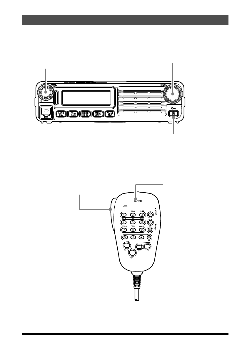
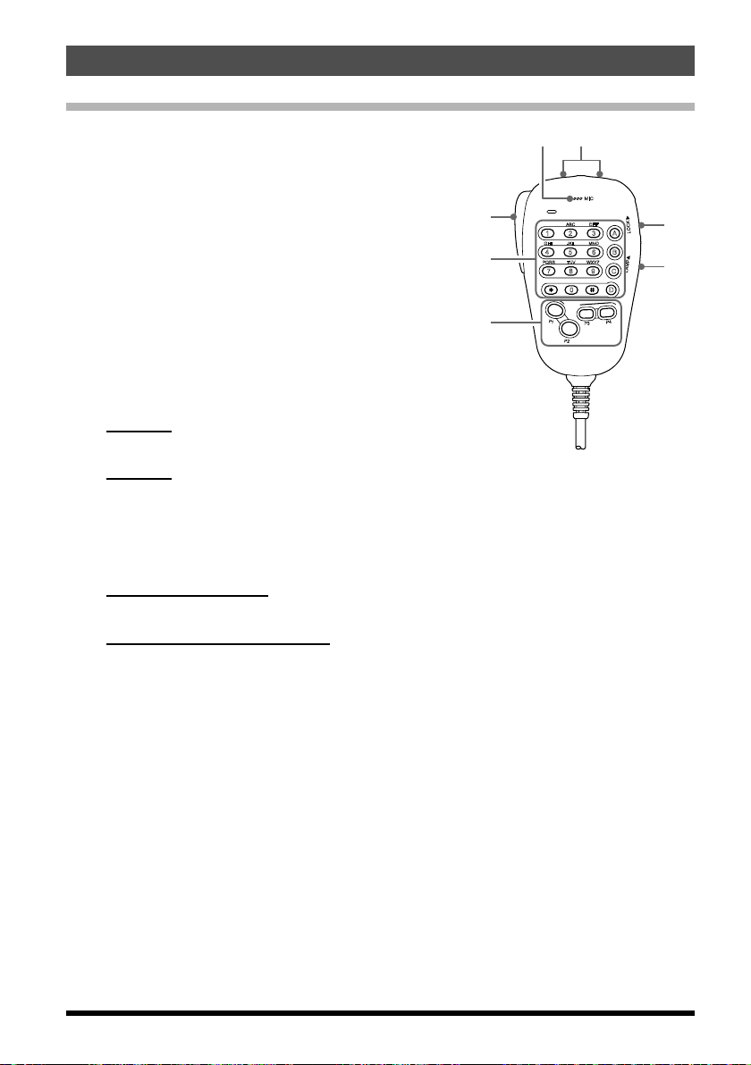
FTM-7250DR Quick Reference Guide
Frequency DIAL Knob
VOL Knob
Adjusts the audio
volume level.
Selects the operating Frequency.
Transmission Switch
Speak into the microphone in
a normal voice level while
pressing this switch.
Power Switch
Press and hold for one second.
Microphone
MIC
ABC
DEF
LOCK
A
JKL
TUV
7
P1
P2
DTMF MICROPHONE
3
2
MNO
5
6
B
WXYZ
8
0
MH-48
LAMP
9
C
D
P4
P3
PQRS
1
GHI
4
3
Page 6

Introduction
Features of this radio
144/430 MHz dual band mobile radio, equipped with a C4FM communication modem.
50 Watts of power output, with selection of three power levels for every operating situ-
ation.
Clear audio and data communication is achieved using the C4FM modem functions.
Expanded receiver coverage: 108.000 MHz - 579.995 MHz.
With the GD-ID (Digital Group ID) feature, the Group Monitor (GM) feature enables au-
tomatically locating, and communicating with other stations that have the same DG-ID
number within contact range, by utilizing a matching group ID number from 00 to 99.
The Digital Personal ID (DP-ID) feature supports communication specifically with
transceivers registered with the individual ID information. The DP-ID is different for
each transceiver and is included in each C4FM transmission.
Easily connect with the WIRES-X linking system.
Keyboard entry of operating frequencies from the microphone.
225 memories (199 “basic” memory channels, 10 sets of band-edge memory channels,
and 6 “Home” channel) which can store repeater shifts, odd repeater shifts, CTCSS/
DCS tones, and 8-character Alpha-Numeric labels for easy channel recognition.
Built-in CTCSS and DCS Encoder/Decoder circuits.
Extensive Menu system, which allows customization of a number of transceiver perfor-
mance characteristics.
Equipped with the GM (Group Monitor) function.
Additional features include a transmit Time-Out-Timer (TOT), Automatic Power-Off (APO),
and Automatic Repeater Shift (ARS). Also included is an RF Squelch circuit that allows
the owner to set the squelch to open at a programmed setting of the S-Meter, thus reducing guesswork in setting the squelch threshold.
Congratulations on your purchase of the FTM-7250DR! Whether this is your first rig, or if
Yaesu equipment is already the backbone of your station, the Yaesu organization is committed to ensuring your enjoyment of this high-performance transceiver. It should provide
you with many years of satisfying operation. Our dealer network and technical support
personnel stand behind every product we sell, and we invite you to contact us should you
require technical advice or assistance.
We recommend that you read this manual in its entirety prior to installing the FTM7250DR, so that you fully understand the capabilities of your new transceiver.
4
Page 7
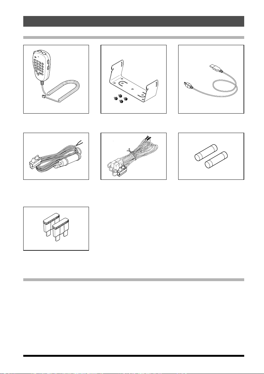
Supplied Accessories
Accessories & Options
DTMF Microphone
MH-48A6JA
DC power cable
(with fuse attached)
(USA, Asian version)
Spare fuse (15 A)
(European version)
Mobile Mounting Bracket
(Attachment screw set)
DC power cable
(with fuse attached)
(European version)
Operating Manual (this manual)
Spare fuse (15 A)
(USA, Asian version)
Optional Accessories
MH-42C6J Microphone
MH-48A6JA DTMF Microphone (Same as the one provided)
MLS-100 High-Power External Speaker
FP-1030A AC Power Supply (25 A) (USA and Asian market only)
FP-1023 AC Power Supply (23 A) (USA market only)
USB cable
5
Page 8
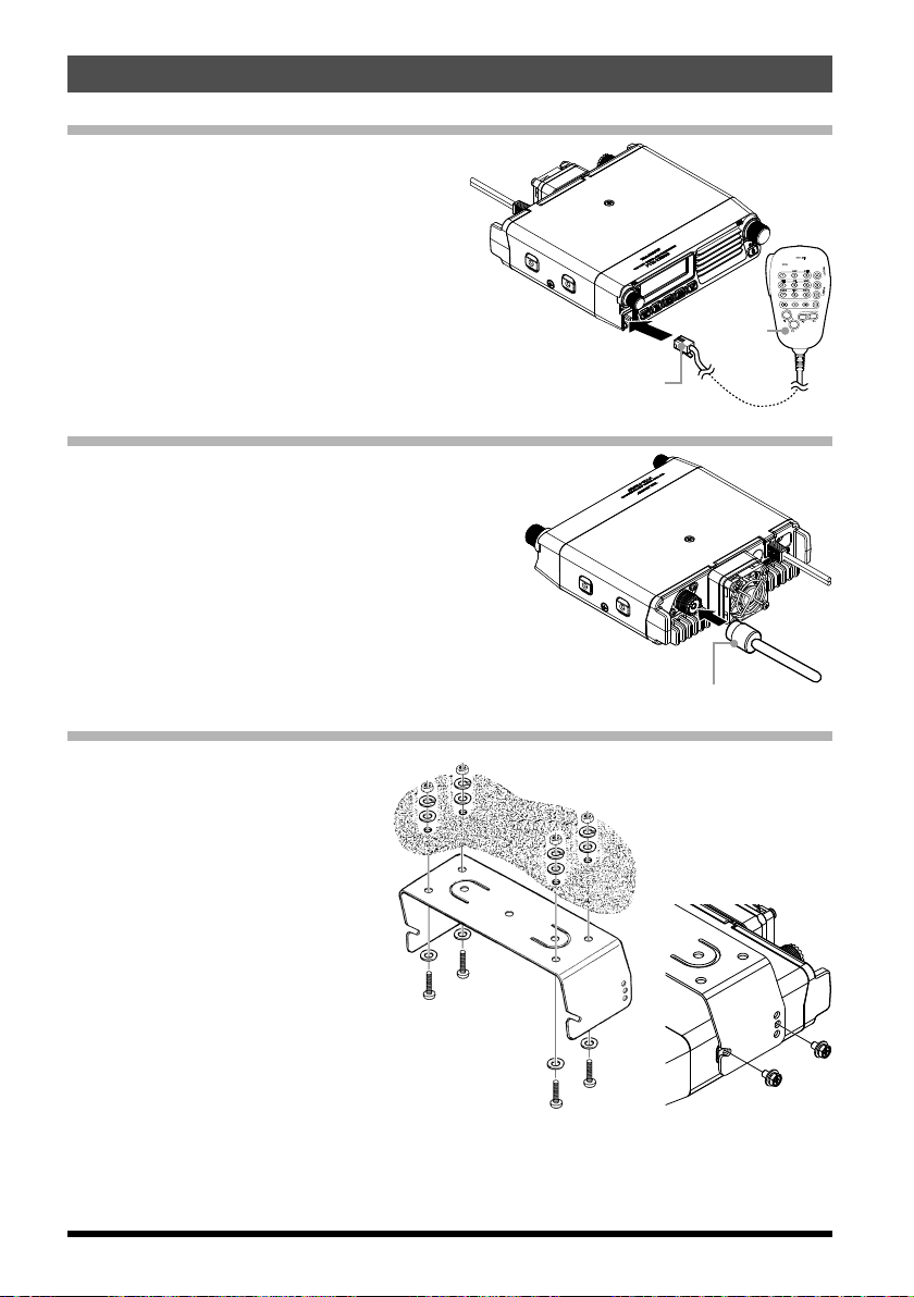
Installation
Coaxial cable plug
Connecting the Microphone
Connect the supplied MH-48A6JA microphone to the FTM-7250DR.
Plug the microphone connector into the MIC
jack on the front panel until it clicks.
Note: When disconnecting the microphone,
pull the cable while pressing the connector latch.
Connecting the Antenna
Connect the coaxial cable to the body.
Plug the coaxial cable jack into the ANT terminal on the rear panel of the body, then rotate and tighten it.
Connector
Microphone
MIC
ABC
DEF
LOCK
A
3
1
2
JKL
GHI
MNO
4
5
6
B
TUV
PQRS
WXYZ
LAMP
7
8
9
C
D
0
P
1
P4
P3
P2
DTMF MICROPHONE
MH-48
Mobile Installation
The FTM-7250DR must only be
installed in vehicles having a 13.8
Volt negative ground electrical
system. Mount the transceiver
where the display, controls, and
microphone are easily accessible, using the supplied mounting
bracket.
The transceiver may be installed
in almost any location, but should
not be positioned near a heating
vent nor anywhere where it might
interfere with driving (either visually or mechanically).
Make sure to provide plenty of space on all sides of the transceiver so that air can flow
freely around the radio’s case. Refer to the diagrams showing proper installation procedures.
6
Page 9
Installation
DC power supply
Fuse holder
Fuse holder
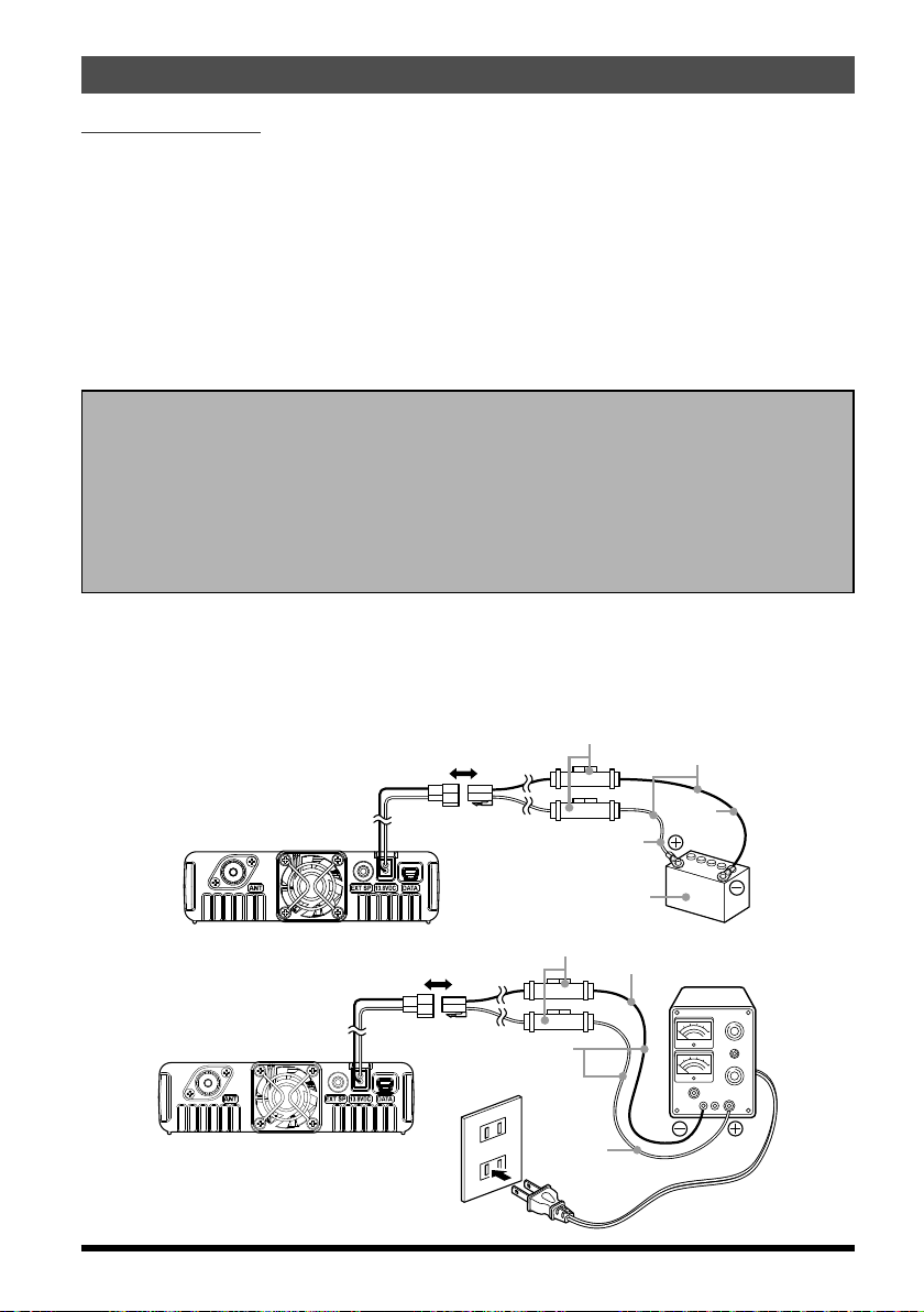
Power connection
To minimize voltage drop and avoid blowing the vehicle’s fuses, connect the supplied
DC power cable directly to the battery terminals. Do not attempt to defeat or bypass the
DC cable fuse - it is there to protect you, your transceiver, and your vehicle’s electrical
system.
Operation of the FTM-7250DR from an AC line requires a power source capable of providing at least 20 Amps continuously at 13.8 Volts DC. The FP-1023 (USA market only)
and FP-1030A (USA/Asian market only) AC Power Supplies are available from your
Yaesu dealer to satisfy these requirements. Other well-regulated power supplies may be
used as well, if they meet the above voltage and current specifications.
Warning!
• Never apply AC power to the power cable of the FTM-7250DR, nor DC voltage greater
than 15.8 Volts. When replacing the fuse, only use a 15 A fuse. Failure to observe these
safety precautions will void the Limited Warranty on this product.
• Do not use a DC power supply cable other than the one that is supplied or specified.
• Do not place anything on the DC power supply cable or step on it.
• Do not use the DC power supply cable with the fuse holder cut off.
• Do not reverse the polarity (positive and negative) when connecting the battery.
r Connect the RED power cable lead to the POSITIVE (+) terminal, and the BLACK
power cable lead to the NEGATIVE (–) terminal. If you need to extend the power cable,
use #12 AWG or larger insulated, stranded copper wire. Solder the splice connections
carefully, and wrap the connections thoroughly with insulating electrical tape.
Power cable
(DC 13.8 V)
Power cable
(DC 13.8 V)
Rear panel
AC power outlet
DC 12 V battery
DC power supply
cable (supplied)
Red
cable (supplied)
Red
Black
Black
Direct current
power supply
7
Page 10
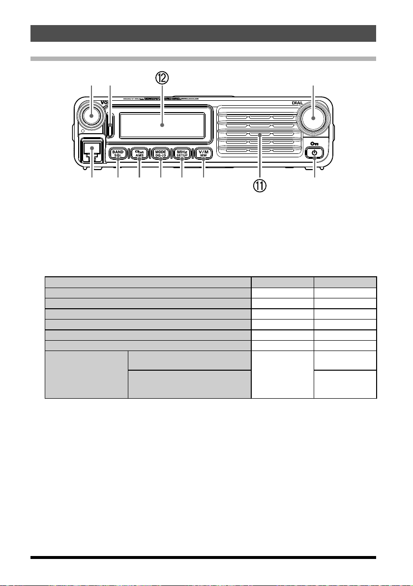
Front Panel Controls & Switches
Front Panel
VOL knob
Turning the knob clockwise increases the volume, whereas turning it counterclockwise decreases the volume.
Mode/Status indicator
Indicates the transmission/reception status with a two-color combination on the upper
and lower portions of the mode/status indicator.
Communication status Upper portion Lower portion
Receiving analog audio Green Green
Transmitting analog audio Red Red
Receiving digital audio Green Blue
Transmitting digital audio Red Blue
Receiving digital data Green White
Receiving signals with unmatched audio or data conditionsø Green Blink in Blue
The other station is within the com-
GM function during
operation
ø •Receiving signals with unmatched tone frequency or DCS code.
•Receiving analog audio in digital mode.
•Receiving signals with unmatched DG-ID in digital mode.
•Receiving a signal level less than the RF Squelch S-meter level setting.
munication range
Transmitting GM confirmation sig-
nal to the other station within the
communication range
-
DIAL Knob
• Allowssettingtheoperatingbandfrequency.
Turning clockwise increases the frequency, whereas turning counterclockwise de-
creases the frequency.
• Allowsselectingthedesireditemsforsetup,memoryregistration,groupmonitoring
operation, etc.
MIC Jack
Connect the provided microphone cable.
Light Blue
Blue
8
Page 11

Front Panel Controls & Switches
S and TX Power Meter
Lock Feature Active
LOW/MID TX Power Selected
CTCSS/DCS/EPCS Bell Paging
[BAND(SQL)] key
A brief press of this key moves operation to the next-highest frequency band.
Press and hold in this key to adjusted the squelch level.
[GM(AMS)] key
Pressing this key to activate the GM (Group Monitor) function.
Press and hold this key to display the transmit mode setting when using the AMS
function.
[MODE(DG-ID)] key
Briefly pressing each time switches the operating band communication mode.
Press and hold in this key to select the DG-ID number registered in the DG-ID memory.
Note: For details, see “Recall and use the DG-ID number registered in the DG-ID
memory” on 20.
[MHz(SETUP)] key
This key allows tuning in 1 MHz steps (the MHz digits will blink on the display).
Press and hold this key to activate the Setup (Menu) Mode.
[V/M(MW)] key
Pressing this key briefly, switches between VFO mode, memory mode, and HOME
channel.
Press and hold the key to display the memory registration screen.
Power/Lock key
Press and hold in this key to switch the power between ON and OFF. Briefly pressing
the key while the transceiver is turned ON engages or releases the key lock.
Speaker
The internal speaker is located here.
LCD Display
The main digits on the display may show the operating frequency, memory name, or
any of many parameters during Menu setup.
(
Continuous Tone Coded Squelch System
GM Feature Active
Frequency/Message
DCS (Digital Code Squelch)
CTCSS
Repeater Shift Direction
Area
Narrow Deviation
AMS Function
)
Communication mode
DTMF Memory Mode
SKIP/Preferential Scan Channel
HOME Channel
Memory mode
Memory Channel Number
GM Feature Communication range indicator
9
Page 12

Rear Panel Connectors
Rear Panel
ANT Coaxial Socket
This is the M-type coaxial connector to connect 144 MHz band and 430 MHz band
antennas (50 ohms). Make sure the antenna is designed specifically for use on the
operating frequency.
EXT SP Jack
This 2-contact 3.5-mm mini phone jack provides receiver audio output for an optional
external speaker. The audio impedance is 4 Ohms, and the level varies according to
the setting of the front panel VOL control. Inserting a plug into this jack disables audio
from the transceiver’s internal speaker.
13.8 V DC Cable
Connect the provided DC power supply cable (with fuse attached).
DATA Jack
Use this jack when updating the firmware. When a new firmware update for the FTM7250DR is available, go to the YAESU website to download the programming data
and update the FTM-7250DR to its newest state.
Cooling Fan
10
Page 13
Microphone Switches
Microphone (MH-48A6JA)
PTT Switch
Press this switch to transmit, and release it to
receive.
KEY Pad Buttons
1 to 0: Enters the numerals.
: Switches between VFO mode, Memory
*
mode, and HOME channel.
#: Scans the programmed memory channels.
A: Changes tuning to 1 MHz steps.
B: Changes the operating band.
C: Adjusts the squelch level.
D: Changes the transmit power.
] / [P2]
[P1
[P1]
keys
key
Press this key to recall the DG-ID memory.
[P2]
key
Press and hold this key to enter the DG-ID memory screen.
[P3]
/ [P4] keys
These two keys are user programmable, allowing quick access to features used often.
The default functions are described below.
[P3]
key (WIRES-X)
Press this key to activate the Wires-X feature.
[P4]
key (WX CH / T CALL)
In the USA version, pressing this key activates the WX function.
In the European/Asian version, pressing this key activates T CALL (1750 Hz) for
repeater access.
You can reprogram the [P3] and [P4] keys for other functions, if desired.
Note: For details, refer to the Advanced Manual (download from the Yaesu website).
MIC
Speak into this port during transmission.
[UP] / [DWN] keys
Press (or hold in) either of these keys to tune (or scan up or down) the operating
frequency or through the memory channels. In many ways, these keys emulate the
function of the (rotary) DIAL knob.
LOCK switch
This switch locks out the Microphone keys (except for the keypad and PTT switch).
LAMP switch
This switch illuminates the Microphone keypad.
1
GHI
4
PQRS
7
P1
MIC
ABC
2
JKL
5
TUV
WXYZ
8
0
P3
P2
DTMF MICROPHONE
MH-48
DEF
LOCK
A
3
MNO
6
B
LAMP
9
C
D
P4
11
Page 14
Basic Operation
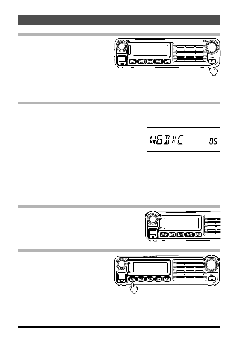
Turning the Transceiver ON and OFF
1. To turn the transceiver ON, press
and hold the PWR/LOCK key.
2. To turn the transceiver OFF, again
press and hold the PWR/LOCK key.
You can compose any desired Opening Message (up to 8 characters) via Setup Menu
Item “OPEN MSG 28” see 40 for details.
Inputting the call sign
A screen requesting input of a call sign appears when turning the transceiver on for the
first time, or after resetting the transceiver. The call sign is used to identify the transmitting station when communicating in digital mode.
1. Press the [V/M(MW)] key.
2. Rotate the DIAL knob to select characters, then
press the [V/M(MW)].
By rotating the DIAL knob, you can switch the
characters in the following order:
“space” à “-” à “/” à “0” to “9” à “A” to “Z”
•Up to 10 characters (alphanumeric characters including hyphen) can be entered.
•“space”, “-”, and “/” are not selectable for the first character.
3. Press and hold the [MHz(SETUP)] key to save the call sign and exit to normal operation.
Adjusting the Audio Volume Level
Rotate the VOL knob to adjust the receiver
Clock-wise rotation increases the audio output level.
volume.
Adjusting the Squelch Setting
1. Press and hold the [BAND(SQL)]
key, then rotate the DAIL knob to
select the Squelch level.
2. Press the [BAND(SQL)] key again.
Note: A special “RF Squelch” feature is provided on this radio. This feature allows
setting the squelch so that only signals exceeding a certain S-meter level will
open the squelch. For details, refer to the Advanced Manual (download from the
Yaesu website).
12
Page 15
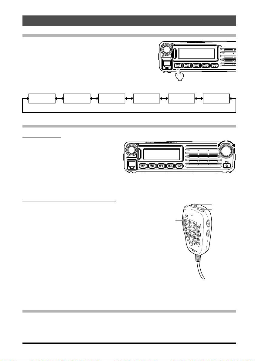
Selecting a Frequency Band
Information
Information
Information
DWN
Number
keys
Press the [MHz(SETUP)] key to select the desired
frequency band.
Frequency ranges for each frequency band are below:
Basic Operation
AIR band
108
137 MHz 137
-
144 MHz band 430 MHz band
174 MHz 174
-
radio band (1
)
222 MHz 222
-
radio band (2
420 MHz 420
-
)
470 MHz 470
-
radio band (3
580MHz
-
)
Frequency Navigation
Using the Dial
Rotating the DIAL knob allows tuning
in the pre-programmed steps. Clockwise rotation tunes the frequency upwards, whereas counterclockwise rotation tunes the frequency downwards.
r Press the [MHz(SETUP)] key momentarily, then rotate the DIAL knob, to change the
frequency steps to 1 MHz per step.
Using the MH-48A6JA Microphone
Using the [UP] and [DWN] key:
Pressing [UP] momentarily, tunes the frequency
UP
upwards. Whereas pressing [DWN] momentarily
tunes the frequency in the downward direction.
Using the number keys:
Use the [0] to [9] number keys to directly input the
frequency.
There is no “decimal point” key on the MH48A6JA keypad. However, there is a short-cut for
frequencies ending in zero:
press the [#] key after the last non-zero digit.
Examples: To enter 446.520 MHz, press [4] à [4] à [6] à [5] à [2] à [0
To enter 446.000 MHz, press [4] à [4] à [6] à [#
]
]
Channel Step Selection
The frequency tuning step of the DIAL and the microphone [UP]/[DWN] keys can be
changed.
Note: See Setup Menu Item “STEP 45” on 41
13
Page 16

Basic Operation
Selecting the communication mode
The FTM-7250DR transceiver is equipped with the AMS (Automatic Mode Select) function which automatically selects from two modes of transmission corresponding to the
signal being received.
The transmit mode is selected according to the received signal so that C4FM digital signals, and analog signals are received and transmitted automatically.
Press [MODE(DG-ID)] key to display “
To operate in fixed communication mode, press
[
MODE(DG-ID)] key to switch the communication
mode.
Each time [MODE(DG-ID)] key is pressed, the communication mode changes in the following order:
” (blinks) icon on the screen.
AMS transmission mode
Display example when in AMS mode
à
à
ø
VW
(“ ” lights up) à FM (no icon) à
à
AMS (“
” blinks) à V/D (DN) (“ ” lights up)
Communication mode Icon Description of modes
Transmit mode is automatically selected from 3
types according to the signal received.
AMS (Automatic Mode Select)
V/D (DN) Mode
(Voice/Data simultaneous
transmission mode)
Voice FR (VW) Mode
(Voice Full Rate mode)
Analog FM Mode no icon
: When the Setup Menu item “DIG VW 13” is set to “ON” (factory default is “OFF”), the
ø
ø
(blinks)
(light up)
The AMS function operation can be changed
from the Setup menu setting. See “Setting the
transmit mode when using the AMS function
(DIG AMS 12)” on 39
Calls are less prone to interruptions due to detection and correction of voice signals during
digital voice signal transmission. This is the
standard mode for C4FM Digital.
High speed data communication using entire
12.5 kHz band. Enables high-quality voice communication.
Analog communication using FM mode.
Effective when the signal is weak and audio is
susceptible to interruption in digital mode.
Voice FR (VW) may be selected.
14
Page 17

Basic Operation
0.5 sec off
: DN mode
: DN mode
0.5 sec off
0.5 sec off
FM mode
0.5 sec off
DN mode
0.5 sec off
VW mode
Setting the transmission mode when using the AMS function
The AMS function will automatically set the receiver to the mode of the received signal,
but the transmission mode may be fixed regardless of the received mode.
1. Press and hold the [GM(AMS)] key.
2. Rotate the DIAL knob to select the
the desired transmission mode as
follows.
AUTO (“ ” blinks: 0.5 sec of, 0.5 sec off)
Automatically selects one of the two
communication modes according to
the received signal.
TXMANUAL (“ ” blinks: 1 sec on, 0.5 sec off)
Automatically selects one of the two
communication modes according to
the received signal.
Briefly pressing
PTT on the microphone switches between digital mode and analog mode.
TX FMFIX (“ ” blinks: 0.5 sec on, 0.5 sec off)
Automatically selects one of the two
communication modes according to
the received signal. Always switches to FM mode for transmission.
: VW mode
: FM mode
Blinks: 0.5 sec on
: FM mode
Blinks: 1 sec on
Blinks: 0.5 sec on
TX DIGTL (“ ” blinks: 0.5 sec on, 0.5 sec off)
Automatically selects one of the two
communication modes according to
the received signal. Always switches to DN mode for transmission.
Blinks: 0.5 sec on
TX VWFIX (“ ” blinks: 0.5 sec on, 0.5 sec off)
Note: When the Setup Menu item “DIG VW 13” is set to “ON” (factory default is “OFF”),
the “TX VWFIX” may be selected.
Automatically selects one of the two
communication modes according to
the received signal. Always switches to VW mode for transmission.
Blinks: 0.5 sec on
3. Press the [GM(AMS)] key to save the new setting and exit to normal operation.
15
Page 18

Basic Operation
MIC
Analog mode: Both the upper and lower portions light red
Transmission
1. Press and hold PTT switch on the microphone.
In analog mode, both the upper and lower portions of
PTT
the mode/status indicator light red.
In digital mode, the upper portion of the mode/status
indicator lights red and the lower portion of the mode/
status indicator lights blue.
Digital mode: The upper portion lights red and the lower portion lights blue
2. Speak into MIC on the microphone.
Note: Keep the microphone about 5 cm away from your mouth.
The sensitivity (gain) of the microphone can be adjusted, use the Setup Menu
Item “MIC GAIN 25” see 40 for details.
3. Release PTT switch.
The transmit mode/status indicator turns off and the transceiver returns to the receive
mode.
Caution: Do not continue transmitting for a prolonged period. The transceiver may
overheat, resulting in malfunction or injury.
Note: “ERROR” appears if you attempt to transmit on an unavailable frequency.
1
GHI
4
PQRS
7
P1
MIC
ABC
2
JKL
5
TUV
8
0
P3
P2
DTMF MICROPHONE
MH-48
DEF
A
3
MNO
6
B
WXYZ
9
C
D
P4
LOCK
LAMP
16
Page 19

Basic Operation
Adjusting the transmit power
When communicating with a nearby station, the transmit power level may be reduced to
save on energy consumption.
1. Press the [D] key on the microphone.
2. Rotate the DIAL knob or press the [UP]/[DWN] key
on the microphone to select the transmit power.
Note: The default setting: HIGH
HIGH (50 W) MID (25 W) LOW (5 W)
3. Press the [D] key to save the new setting and exit to normal operation.
Lock Feature
To activate the key-lock feature, press
the [Power(Lock)] key. The “
icon will appear on the LCD.
To cancel key-lock, press the [Pow-
er(Lock)] key again.
”
1
GHI
4
PQRS
7
P1
MIC
ABC
2
JKL
5
TUV
8
0
P3
P2
DTMF MICROPHONE
MH-48
DEF
LOCK
A
3
MNO
6
B
WXYZ
LAMP
9
C
D
D key
P4
To select which keys are locked, use the Setup Menu Item “LOCK 24” see 40 for details.
17
Page 20

Advanced Operation
The group member set the DG-ID number to “50”
Setting the receive DG-ID number to
)
)
About the Digital Group ID (DG-ID) feature
The DG-ID function can set up two-digit DG-ID numbers from “00” to “99” separately for
Transmit and Receive. By setting both transmit and receive to “00” (default), you can
communicate with all the other stations in the digital C4FM mode.
By matching the transmit DG-ID number to the uplink DG-ID number set in the club DR2X/XE System Fusion II digital repeater, you can access the digital repeater DR-2X/XE
used in the club.
For communication only among a group of friend’s transceivers, you can all match the
same DG-ID number; then only your friend’s voices will be heard. Also, by using the GM
function you can check whether stations with the same DG-ID are in the communication
range. The FTM-7250DR may register transmit and receive DG-ID numbers in the DG-ID
memories (up to 10 pairs), and then use the [P1] / [P2] keys on the microphone to easily
recall a Group ID.
“00” , all the C4FM digital stations
may be received signals
DG-ID
T50 (transmit
R50 (receive
Only group members set to the same DG-ID
number may communicate.
)
)
DG-ID
T50 (transmit
R50 (receive
DG-ID
)
)
T00 (transmit
R00 (receive
T90 (transmit
R90 (receive
The other station set the receive DG-ID
number to the number except for “00”
may not received the signals that is not
matching the DG-ID number.
)
)
DG-ID
)
)
DG-ID
T00 (transmit
R00 (receive
18
Page 21

Advanced Operation
Register the DG-ID number in the DG-ID memory
Example: Enter the transmit DG-ID number “50” and the receive DG-ID number “00”
into the DG-ID memory “01”
1. Press and hold the
The DG-ID memory number at the bottom right of
the screen blinks.
2. Rotate the DIAL knob or press the [UP]/[DWN]
key on the microphone to select the DG-ID memory number to be stored to the “01” register.
3. Press the [P2] key on the microphone.
The transmit DG-ID number “T00” blinks.
4. Rotate the DIAL knob or press the [UP]/[DWN]
key on the microphone to set the transmit DG-ID
number to “T50”.
5. Press the [P2] key on the microphone.
The transmit DG-ID number blinks.
6. Rotate the DIAL knob or press the [UP]/[DWN]
key on the microphone to set the receive DG-ID
to “R00”.
7. Press the [P2] key on the microphone.
•The input screen of the DG-ID tag is displayed.
[P2]
key on the microphone.
•Use the numeric keys on the microphone or the DIAL knob to input the characters of
the DG-ID tag. Up to 8 characters can be entered.
Press the [P3] key on the microphone or [BAND(SQL)] key to move the cursor to
the left.
Press the [P4] key on the microphone or [V/M (MW)] key to move the cursor to the
right.
8. Press and hold the [P2] key on the microphone to save the setting and return to normal
operation.
Notes:
•The DG-ID memory “00” is fixed at “T00 R00” and cannot be changed.
•By pressing and holding the [P2] key on the microphone in the middle of the setting,
the setting so far will write and then return to the normal screen.
•When the [P2] key on the microphone is not pressed while writing, after five seconds
elapse the operation will return to the normal screen without saving the setting.
19
Page 22

Advanced Operation
Recall and use the DG-ID number registered in the DG-ID memory
1. Press the [P1] key on the microphone, the information of the current DG-ID is displayed.
2. Rotate the DIAL knob or press the [UP]/[DWN]
key on the microphone to select the number of
DG-ID List to recall.
3. Press the PTT switch to select the DG-ID number and return to the frequency display screen.
Or if five seconds passes, the selected screen
will return to frequency screen automatically.
•When using the DG-ID memory, the tag of the
DG-ID memory being used is displayed every
3 seconds.
•If the DG-ID memory is “00”, DG-ID memory tag
is not displayed.
4. Press the [P1] key on the microphone to switch to the DG-ID number display as shown
below. When the DG-ID memory is “00”, no DG-ID tag is displayed, only the DG-ID
number “00” is displayed.
DG-ID Tag display à DG-ID Number display à Normal Screen
•If there is no operation for more than five seconds, the display returns to the normal
frequency display screen.
•Press and hold the [P1] key on the microphone while on the frequency display screen.
The DG-ID memory returns to DG-ID memory “00” with one touch.
DG-ID Tag display
DG-ID Number display
20
Page 23

Advanced Operation
DG-ID: TX01 RX01
Each transceivers may communicate
B Station may not receive the C
station's signal because B station does
C station may receive the B station's
signal because C station register the B
Digital Personal ID (DP-ID) feature
Every C4FM digital transmit communication contains the individual ID information (Radio
ID) of each transceiver. The DP-ID function uses this individual ID information.
When communicating with another transceiver, if the DP-ID of the stations are registered
in each other‘s transceivers, they can communicate even if the DG-ID numbers are
different.
even if the Digital Group ID (DG-ID) is
a different setting because A Station
and B station register the DP-ID of
each other’ s transceiver on both
trasnceivers.
DP-ID list
B station's DP-ID “bbbbb”
A B
DP-ID: aaaaa
DG-ID: TX01 RX01
DP-ID: bbbbb
DG-ID: TX02 RX02
DP-ID list
A station's DP-ID “aaaaa”
A station and C station do not register
the DP-ID of each other’ s transceiver
on both transceivers, but each
transceivers may communicate
because the same DG-ID is set to
both transceivers.
C
B station's DP-ID “bbbbb”
DP-ID: ccccc
not register the C station's DP-ID.
station's DP-ID.
DP-ID list
Registering the DP-ID to a DR-2X digital repeater
Note: To register the transceiver DP-ID in the System Fusion II, DR-2X C4FM digital
repeater, refer to the instruction manual of the DR-2X.
By registering the transceiver’s DP-ID in the DR-2X, you can remotely control the settings
and functions of DR-2X. Remote control cannot be performed from a transceiver that
does not register the DP-ID, so it is possible to securely manage repeaters.
DR-2X Remote Control Feature
•Activate the repeater operation
•Deactivate the repeater operation
•Set the repeater to C4FM mode
•Set the transmit power
•Voice Message Control (Rec / Play / Stop)
•Set the Emergency Call
21
Page 24

Advanced Operation
Register the transceivers
1. Press and hold the [MHz(SETUP)] key to enter the
Setup Menu.
2. Rotate DIAL knob to select “DPID LST 15”.
3. Press the [MHz(SETUP)] key.
The DP-ID List is displayed.
4. While the DP-ID list is displayed, a
transmission in the digital C4FM mode
from the other transceiver will register
the DP-ID.
When a signal from the other station
is received, the call sign is displayed
on the LCD.
Notes:
•When a signal from the already registered transceiver is received, the display of DP-
ID list does not change.
•When registering a transceiver already registered with a different call sign, the call
sign registered in the DP-ID list is changed to registrar the new call sign.
5. Press and hold the [MODE(DG-ID)] key to save
the setting.
•When registering in the DP-ID list is finished,
“COMPLETE” is displayed, then the display returns to the DP-ID list screen.
•To continue operating without registering the
DP-ID, press the [MODE(DG-ID)] key.
•If registering several DP-IDs, repeat steps 4 to
5.
•A maximum of 24 stations may be registered.
6. Press and hold the [MHz(SETUP)] key to return to normal operation.
Register the DP-ID of all the transceivers in the group to another transceiver using the
same operation.
Notes:
•Once the DP-ID is registered, the DP-ID is stored until the DG-ID is deleted.
•Register with the another transceiver while each other’s transceivers are nearby.
22
Page 25

Advanced Operation
Deleting the registered DP-ID
1. Press and hold the [MHz(SETUP)] key to enter
the Setup Menu.
2. Rotate DIAL knob to select “DPID LST 15”.
3. Press the [MHz(SETUP)] key.
The DP-ID List is displayed.
4. Rotate the DIAL knob to select the call sign.
5. Press and hold the [MODE(DG-ID)] key
The confirmation
6. Press and hold the [MODE(DG-ID)] key again to
delete.
•When deleting in the DP-ID list is finished,
“COMPLETE” is displayed for three seconds,
then the display returns to the DP-ID list screen.
•To return to normal operation without deleting
the DP-ID, press the [MODE(DG-ID)] key.
•If deleting several DP-IDs, repeat steps 4 to 6.
7. Press and hold the [MHz(SETUP)] key to return to normal operation.
screen
is displayed.
23
Page 26

Advanced Operation
Repeater Operation
The FTM-7250DR includes the ARS (Automatic Repeater Shift) function, which permits
communication through repeaters automatically, by simply setting the receiver to the repeater frequency.
1. Tune to the repeater frequency.
2. Press the PTT switch to transmit.
During transmission, radio waves having an 100.0 Hz* tone signal are emitted on the
frequency offset from the receive frequency by 0.6 MHz* (144 MHz) or 5 MHz (430
MHz)*.
*: Depends on the transceiver version.
Note: From the Setup Menu, you can change the repeater setting.
RPT ARS 35 à Deactivates the ARS function.
RPT FREQ 36 à Allows changing the repeater shift frequency offset.
RPT SFT 37 à Allows setting the repeater shift direction.
Checking the Repeater Uplink (Input) Frequency
It is often helpful to be able to check the uplink (input) frequency of a repeater, to see if
the calling station is within direct (“Simplex”) range.
Note: For details, refer to the Advanced Manual (download from the Yaesu website).
Tone Calling (1750 Hz)
If your transceiver is FTM-7250DE (European version), press and hold in the program key
[P4]
of the microphone (MH-48) to generates a 1750 Hz burst tone to access the European
repeater. The transmitter will automatically be activated, and a 1750 Hz audio tone will
be superimposed on the carrier. Once access to the repeater has been gained, you may
release the [P4] key, and use the PTT switch for activating the transmitter thereafter.
24
Page 27

Advanced Operation
PTT
P4 key
Weather Broadcast Reception (USA version only)
The FTM-7250DR includes a unique feature which allows reception of weather broadcasts in the 160 MHz frequency range. Ten standard Weather Broadcast channels are
preloaded into a special memory bank.
To listen to a Weather Broadcast Channel (Example: When “WX CH” is assigned to [P4]):
1. Press the Microphone [P4] key to recall the Weather
Broadcast channels.
Note: In the USA model, the [P4] key one of the pro-
grammable keys, is assigned (default setting)
as the “WX Broad-cast” one-touch access key.
Please note that if you change/assign another
function to the [P4] key, one-touch access to
the WX channel will be unavailable.
2. Turn the DIAL knob to select the desired Weather Broadcast channel.
CH Frequency CH Frequency
1 162.550 MHz 6 162.500 MHz
2 162.400 MHz 7 162.525 MHz
3 162.475 MHz 8 161.650 MHz
4 162.425 MHz 9 161.775 MHz
5 162.450 MHz 10 163.275 MHz
1
GHI
4
PQRS
7
P1
MIC
ABC
2
JKL
5
TUV
8
0
P3
P2
DTMF MICROPHONE
MH-48
DEF
LOCK
A
3
MNO
6
B
WXYZ
LAMP
9
C
D
P4
3. To scan the other channels for activity, press the Microphone PTT switch.
4. To exit to normal operation, press the [P4] key again. Operation will return to the VFO
or Memory channel in operation before you began Weather Broadcast operation.
Severe Weather Alert Feature
In the event of extreme weather disturbances, such as storms and hurricanes, NOAA (the
National Oceanic and Atmospheric Administration) sends a weather alert accompanied
by a 1050 Hz tone and subsequent weather report on one of the NOAA weather channels.
You may enable this feature via Setup Menu Item “WX ALERT 53” (USA version only).
25
Page 28

Memory Operation
The FTM-7250DR provides a wide variety of memory system resources. These include:
r 199 “basic” memory channels, numbered “1” through “199”.
r 6 “Home” channels. A Home Channel can be set and recalled on each frequency band.
r 10 sets of band-edge memories, also known as “Programmable Memory Scan”
channels, labeled “L0/U0” through “L9/U9”.
Each memory may be appended with an alphanumeric label of up to 8 characters, for
quick channel recognition.
Memory Storage
1. In the VFO mode, select the desired frequency and the communication mode to be
registered to a memory channel.
2. Press and hold the [V/M(MW)] key.
A memory number will appear in the
bottom right corner of the display.
Note: If the channel number is blinking, there currently is no data stored on that chan-
nel; if the channel number is not blinking, that channel is currently “occupied” by
other frequency data.
3. Rotate the DIAL knob to select the desired memory into which you wish to store the frequency.
Note: While operating in the Memory Storage mode, the keypad of the MH-48A6JA
Microphone may be used to enter the memory channel number directly.
To do this, enter the desired Channel Number on the keypad. Refer to the “For
example” of the “Memory Recall from the Microphone Keypad“ on page 27.
4. Press the [V/M(MW)] key.
The memory tag input screen will be displayed
on the display.
If not entering a nametag à proceed to step 8.
5. Rotate the DIAL knob to select the first digit of
the desired label.
6. Press the [V/M(MW)] key to move to the next
character.
To make a correction, press the [BAND(SQL)] key to move the cursor to the left, then
re-enter the correct letter, number, or symbol.
7. Repeat steps 5 through 6 to program the re-maining letters, numbers, or symbols of the desired
label. A total of 8 characters may be used in the
creation of a label.
26
Page 29

Memory Operation
8. Press and hold the [V/M(MW)] key, to store the displayed data into the selected
memory channel slot.
Split Memory
A separate transmit frequency may be registered to a memory channel to which a receive
frequency has already been registered.
Note: For details, refer to the Advanced Manual (download from the Yaesu website).
Memory Recall
Once the desired frequencies are stored into memory channels, switch from the “VFO”
mode to the “Memory Recall” mode, to operate on the just-stored memory channels.
1. Press the [V/M(MW)] key, repeatedly if necessary, until the “MR” icon
and a memory channel number appear on the display; this indicates
that the “Memory Recall” mode is
now engaged.
2. When more than one memory has
been stored, use the DIAL knob
to select any of the programmed
memories for operation.
Note:
•Alternatively, the microphone [UP] or [DWN] key may be used to step or scan through
the available memories. When using the microphone keys, press the key momentarily to move one step up or down; press and hold the [UP] or [DWN] key to begin
memory scanning.
•While operating in the Memory Recall mode, press the [MHz(SETUP)] key to toggle
the display between indication of the frequency, and indication of the Alpha/Numeric
label.
Memory Recall from the Microphone Keypad
While operating in the Memory Recall mode, the keypad of the MH-48A6JA Microphone
may be used for direct recall of memory channels.
To do this, enter the desired Channel Number on the keypad.
For example: To recall Memory Channel “7”, press [0] à [0] à [7] or [7] à [#
To recall Memory Channel “123”, press [1] à [2] à [3
You may also recall Programmable Memory Scan (PMS) channels (“L0/U0” through “L9/
U9”) by entering the channel numbers listed in the below table:
L1 201 L3 205 L5 209 L7 213 L9 217
U1 202 U3 206 U5 210 U7 214 U9 218
L2 203 L4 207 L6 211 L8 215 L0 219
U2 204 U4 208 U6 212 U8 216 U0 220
]
]
27
Page 30

Memory Operation
Moving Memory Data to the VFO
Data stored on memory channels can easily be moved to the VFO.
Note: For details, refer to the Advanced Manual (download from the Yaesu website).
Memory Only Mode
Once memory channel programming has been completed, you may place the radio in a
“Memory Only” mode, whereby VFO operation is impossible.
Note: For details, refer to the Advanced Manual (download from the Yaesu website).
Masking Memories
There may be situations where you want to “Mask” memories so they are not visible
during memory selection or scanning. (except for Memory Channel “1”, the Priority Channel, and the Home Channel).
1. In the Memory Recall mode, press
and hold the [V/M(MW)] key, then
rotate the DIAL knob to select the
memory channel you wish to mask.
2. Press the [BAND(SQL)] key.
The erase confirmation screen appears.
3. Press the [BAND(SQL)] key.
The previously selected memory
will be “masked”.
]
)
Note: Press any key, other than [BAND(SQL
Unmasking Memories
1. To Unmask a hidden memory, in the Memory Recall mode, press and hold the
[
V/M(MW)] key.
2. Rotate the DIAL knob to select the masked memory number.
3. Press the [BAND(SQL)] key to restore the memory channel data.
, to cancel the memory mask.
28
Page 31

Memory Operation
HOME Channel Memory
A convenient “Home” channel memory is available to simplify returning to an often used
frequency.
To recall the Home channel, just press the
[
V/M(MW)] key, repeatedly if necessary, until the
“HM” icon appears on the display.
“HM” and the home channel frequency of the currently selected band appears on the LCD.
Changing the frequency of the home channel
The default frequency setting of the home channel can be changed.
1. In the VFO mode, tune to the desired Home channel frequency.
2. Press and hold the [V/M(MW)] key.
3. Press the [GM(AMS)] key.
The overwrite confirmation screen appears.
4. Press the [GM(AMS)] key.
The HOME channel tag input screen will be displayed.
If not entering a nametag à proceed to step 8.
5. Rotate the DIAL knob to select the first digit of
the desired label.
6. Press the [V/M(MW)] key to move to the next
character.
7. Repeat steps 5 through 6 to program the re-maining letters, numbers, or symbols of the desired
label. A total of 8 characters may be used in the
creation of a label.
8. Press and hold the [GM(AMS)] key.
The home channel frequency is overwritten.
29
Page 32

Scanning
DWN UP
Basic Scanner Operation
Before activating the scanner, make sure that the Squelch is set to silence the background noise when no signal is present. Scanning is not possible while the Squelch is
open (if noise or signals are being heard).
Scanning may be started or stopped using the microphone
[UP]
or [DWN] key.
The following techniques are used for scanning:
r in the VFO mode, press and hold either the [UP] or
[
DWN] key, to start upward or downward scanning of
the band.
r In the Memory mode, press and hold either the [UP] or
[
DWN] key, to start channel scanning toward a higher or
lower-numbered memory channel, respectively.
r Scanning pauses when a signal opens the squelch, and the decimal point on the dis-
play will blink. You can choose one of three scan resume modes.
r To halt the scan manually, the easiest way is to push the PTT switch on the microphone
momentarily (no transmission will occur while you are scanning). The scan may also
be halted manually by pressing the microphone [UP] or [DWN] key, or the [V/M(MW)]
key.
Scan Resume Options
Select which of the three resume scan modes is to be performed after the scanning stops.
Note: For details, refer to the Advanced Manual (download from the Yaesu website).
Memory Skip Scanning
Memory channels which you do not want to receive can be skipped during scanning.
Note: For details, refer to the Advanced Manual (download from the Yaesu website).
Preferential Memory Scan
Set up a “Preferential Scan List” of channels which you can “flag” within the memory system.
Note: For details, refer to the Advanced Manual (download from the Yaesu website).
Programmable Memory Scan (PMS)
Using the dedicated PMS memory channels, only the frequencies within the specified
frequency range will be scanned.
Note: For details, refer to the Advanced Manual (download from the Yaesu website).
Priority Channel Scanning (Dual Watch)
Scanning features include a two-channel scanning capability which allows you to operate
on a VFO, Memory channel, or Home channel, while periodically checking a user defined
Memory Channel for activity.
Note: For details, refer to the Advanced Manual (download from the Yaesu website).
1
GHI
4
PQRS
7
P
1
ABC
2
JKL
5
TUV
8
0
P2
DTMF MICROPHONE
MH-48
MIC
P3
DEF
LOCK
A
3
MNO
6
B
WXYZ
LAMP
9
C
D
P4
30
Page 33

GM Function
What is the GM (Group Monitor) Function?
The GM function automatically monitors the channel for any other stations with the GM
function in operation on the same frequency, or stations transmitting in DN mode that are
within communication range. You can be notified of GM stations operating within communications range, and the detected call signs are displayed on the transceiver screen,
Caution: The GM function does not work while in the analog (FM) mode.
à
Displaying all the stations using the GM function
1. Tune to the designated frequency.
2. Press the [GM(AMS)] key.
The GM function is activated, and
up to 24 stations using the GM
mode, or stations operating in DN
mode on the channel frequency,
within the communication range are
displayed.
•Displays “ ” for stations within your communi-
cation range.
•Displays “
communication range.
•Turn the DIAL knob to select a station and dis-
play its communication range information.
3. Press the [GM(AMS)] key to disable the GM function and return to the frequency
screen.
Note: Refer to the Advanced Manual for other details on using the GM function (download
the Advanced Manual from the Yaesu website).
” (blinks) for stations outside of your
31
Page 34

Reset Procedure/Clone
Reset Procedure
In some instances of erratic or unpredictable operation, the cause may be corruption of
data in the microprocessor (due to static electricity, etc.). If this happens, resetting the
microprocessor may restore normal operation. Note that all memories will be erased if
you do a complete microprocessor reset, as described below.
Microprocessor Resetting
To clear all memories and other settings to factory defaults:
1. Turn the radio OFF.
2. Press and hold the [MODE(DG-ID)], [MHz(SETUP)], and [V/M(MW)] keys while turning
the radio on. The “ALL RESET PUSH V/M KEY” notation will scroll on the display.
3. Press the [V/M(MW)] key momentarily to reset all settings to their factory defaults
(press any other key to cancel the Reset procedure).
Setup (Menu) Mode Resetting
To reset the Setup (Menu) Mode settings to their factory defaults, while leaving other
settings unchanged:
1. Turn the radio OFF.
2. Press and hold the [MODE(DG-ID)] and [MHz(SETUP)] keys while turning the radio
on. The “SET MODE RESET PUSH V/M KEY” notation will scroll on the display.
3. Press the [V/M(MW)] key momentarily to reset the Setup (Menu) Mode settings to their
factory defaults (press any other key to cancel the Reset procedure).
Clone
The FTM-7250DR includes a convenient “Clone” feature, which allows the memory and
configuration data from one transceiver to be transferred to another FTM-7250DR.
This can be particularly useful when configuring a number of transceivers for a public
service operation.
Note: For details, refer to the Advanced Manual (download from the Yaesu website).
32
Page 35

Connecting the WIRES-X feature
What is WIRES-X?
WIRES-X is an Internet communication system which expands the range of amateur
radio communication. You may employ Internet communications by connecting from your
transceiver to a WIRES-X local node station.
* FTM-7250DR does not accommodate the transmission/reception of messages, images,
audio messages, or location information.
Connecting to a WIRES-X digital node (Recommended)
* Ascertain the DSQ code or the DG-ID setting of the WIRES-X node station. Connecting
to the WIRES-X node requires the transceiver DG-ID be set according to the DSQ code
or the DG-ID code set on the WIRES-X node station.
* Confirm that the operating mode of WIRES-X node has been set to the C4FM digital
mode.
1. Set the transmit/receive DG-ID to the same ID number as the node station.
For more details on the DG-ID number, see page 18
2. Transmit on the corresponding transmit/receive frequency.
•If the signal is received from the node, continue to transmit using the DG-ID setting
as is.
•If the signal is not received from the node. à proceed to “Connecting to the other
node ID or the other room ID”
Connecting to the other node ID or the other room ID
1. Press and hold the [MHz(SETUP)] key to enter the Setup Menu.
2. Rotate the DIAL knob to select “W-DGID 56* (54)”, then press the [MHz(SETUP)] key.
(*: USA version)
3. Rotate the DIAL knob to set the WIRES-X DG-ID to the same ID number as the node
station.
Display Description
DGID 01 - 99 Only nodes matching the set DG-ID number may be connected.
AUTO
(default setting)
4. Press the PTT switch, or press and hold the [MHz(SETUP)] key to save the new setting
and return to normal operation.
5. Press the [P3] key.
“WIRES“ blinks.
Only open nodes, set to the DG-ID number "00" may be connected.
33
Page 36

Connecting the WIRES-X feature
After successfully connecting to the node, one of the following screens is displayed
indicating the node status.
r 1. Node ID screen (the Node Lc screen)
• This screen is displayed if the node is
disconnected from the other node or the
room on the Internet.
• The node station’s node ID is displayed.
• Continue to select a connecting node à proceed to step 6
r 2. Connecting to a node ID or room ID
screen (the Cn screen)
• This screen is displayed when the node
has been connected to a node or room on
the Internet.
• The connecting node station’s node ID is displayed.
• If not changing the connecting node/room à proceed to step 7.
• When changing the connecting node/room à proceed to step 6.
Note:If the node connection is not successful, the beep sound is emitted and the transceiver
returns to the normal operation.
6. Rotate the DIAL knob to select one of the connection screens (see below information),
and connect to the desired node/room.
Connecting to the node ID or
room ID screen (the Cn screen)
Node ID screen
(the Node Lc screen)
The most recent connected node ID
or room ID screen (the C0 screen)
Direct entry screen
(the En screen)
r The most recent connected node ID or
room ID screen (the C0 screen)
Most recent connected node ID or room ID is
displayed. A single press of the [#] key on this
screen will connect to the most recent node/
room.
r Registered node ID or room ID screen (the
C1-C5 screen)
Rotate the DIAL knob to select a previously
registered node/room (maximum 5 nodes/
rooms) on the C1-C5 screen and, then press
the [#] key or the PTT switch to connect to the
node/room.
34
Registered node ID or room ID
screen (the C1 - C5 screen)
Page 37

Connecting the WIRES-X feature
•Registering the node/room:
Press and hold the [1]-[5] key to register the node/room
(C1-C5) on the connected node ID or room ID (Cn).
•Cancelling the connected node/room: Select the node/room (C1-C5) then
press and hold the [C] key to delete the
registered node/room.
r Direct entry screen (En)
Direct connection to a node or room may be
made by inputting the other node ID or room
ID (5 digits) manually.
• Pressing the numeric keys (5 digits), and then press the [#] key, will request con-
nection with another node ID or room ID.
•Clearing the input node ID or room ID: Press and hold the [C] key
[
•Cancelling the input node ID or room ID: Pressing the
node ID screen (Lc) or the connecting
]
key to return to the
*
node ID or room ID screen.
Note: When a node has been connected, the node or room connection may be
changed by inputting a different node ID or room ID.
When connecting to a node or room,
"CONNECT" is displayed on the screen, and
the display is automatically switched to the
connecting node ID or room ID screen (Cn).
Note: In the case when the selected node or room is not connected, the screen will
display one of the below icons.
“OFFLINE” (Node or room is not in operation.)
”BUSY” (Another node is connecting.)
7. Transmit to communicate with the WIRES-X Internet Link.
]
[
Note: Operations of the microphone [#], PTT,
below chart:
Operation method
(operation screen)
Press the [#] key or the PTT switch
(C0 / C1 to C5 / En screen*)
Press and hold the
(Lc / Cn / C0 / C1 to C5 / En screen)
Press and hold the [1] to [5] key
(Cn screen)
Press the [A] key
(On activating WIRES-X)
[*]
key
Connect to the displayed node/room or change the
destination connection.
(*The PTT switch is disabled on the En screen)
Disconnect from the connected node or room.
The connected node or room ID is registered to the
memory of the number when it is pressed and held (In
case the memory is already written, the registration is
overwritten).
Temporarily displays the operating frequency (when
calling C4FM digital signal, the callsign of the other station is displayed).
Press the [A] key again to return to the previous screen.
, and [A] keys, are described in the
*
Description
35
Page 38

Connecting the WIRES-X feature
8. When communication is completed, press and hold the microphone [P3] key to Exit
WIRES-X mode.
Note: About WIRES-X open node stations
A listing of the WIRES-X open node stations, with their location, operation mode, etc.
is posted on the Yaesu WIRES-X website.
https://www.yaesu.com/jp/en/wires-x/index.php
Connect and communicate with WIRES-X in analog mode
In analog mode, specify the connection destination using DTMF signals.
1. In the normal operating screen, press the [MODE(DG-ID)] key to set the analog FM
mode, and then tune to the frequency of the node station.
Note: When DTMF function is set to “AUTO” (“
to “MANUAL” using the following steps.
Press and hold the [MHz(SETUP)] key à Rotate the DIAL knob to select “DT
AUTO 16” à Press the [MHz(SETUP)] key à Rotate the DIAL knob to select
“MANUAL” à Press and hold the [MHz(SETUP)].
2. While holding down the PTT switch on the microphone, press the [#] key and then
enter the 5 digit ID number of the node or room to be connected, the DTMF code will
be sent to the node station.
3. Keep the transceiver in receive mode for about 10 seconds. Once connection is established, you will be able to hear audio.
Note: The connected destination screen will not appear.
4. Face the microphone and speak.
” icon displayed on the LCD), change
Disconnecting from the node or room
1. While pressing the PTT switch, then enter the “#99999” (DTMF disconnect command)
keys.
Note: In analog mode, the excellent C4FM features such as clear voice, digital in-
formation etc cannot be used, so we recommend using digital C4FM when
communicating with the WIRES-X Internet Linking System.
36
Page 39

Miscellaneous Settings
Tone squelch feature
The tone squelch opens the speaker audio only when a signal containing the specified
CTCSS tone is received. By matching the tone frequency with the partner station in advance, a quiet standby is possible.
Note: For details, refer to the Advanced Manual (download from the Yaesu website).
Digital Code squelch (DCS) feature
DCS (Digital Coded Squelch) function that allows audio to be heard only when signals
containing the same DCS code are received.
Note: For details, refer to the Advanced Manual (download from the Yaesu website).
EPCS (Enhanced Paging & Code Squelch) Operation
Use the pager code consisting of two CTCSS tones to exchange communications with
specified stations.
Note: For details, refer to the Advanced Manual (download from the Yaesu website).
Programming the Key Assignments
Default FTM-7250DR key functions have been assigned to the Microphone’s [P3]/[P4]
keys at the factory. The user may change these key function assignments, if quick access
to another function is desired.
Note: For details, refer to the Advanced Manual (download from the Yaesu website).
Keyboard Beeper
A key/button beeper provides useful audible feedback whenever a key/button is pressed.
If you want to turn the beeper off (or back on again).
Note: If you want to turn the beeper off (or back on again), see Setup Menu Item “BEP
KEY 3” on 39.
Display Brightness
You can adjust the display brightness.
Note: See Setup Menu Item “LCD DMMR 23” on 40.
Time-Out-Timer (TOT)
The “Time-Out Timer” (TOT) feature is designed to force the transceiver into the “receive”
mode after a preset time period of continuous transmission (the default is 3 minutes).
Note: See Setup Menu Item “TOT 48” on 41.
Automatic Power Off (APO)
The “Automatic Power-Off” (APO) feature will turn the radio completely off after a user
defined period of PTT switch or key/button inactivity.
Note: See Setup Menu Item “APO 1” on 39.
Busy Channel Lock-Out (BCLO)
The BCLO feature prevents the transmitter from being activated whenever a signal strong
enough to break through the “noise” squelch is present on the frequency.
Note: See Setup Menu Item “BCLO 2” on 39.
37
Page 40

Miscellaneous Settings
TX Deviation Level
You can reduce the receiver bandwidth and transmit deviation when operating on closely
spaced frequencies (channel spacing of 12.5 or 15 kHz). The reduced transmitter deviation will minimize adjacent channel interference to other users.
Note: See Setup Menu Item “W/N DEV 55* (53)” on 41. (*: USA version)
Displaying the Supply Voltage
Display the Power Supply voltage.
Note: See Setup Menu Item “DC VOLT 9” on 39.
MIC Gain Setting
At the factory, the microphone gain has been programmed so that it should be satisfactory for the supplied MH-48A6JA Microphone. If you use an after-market microphone or
connect a TNC, you may wish to set a different Mic Gain level.
Note: See Setup Menu Item “MIC GAIN 25” on 40.
Displaying the Temperature
Indicates the current final transistor & heatsink temperature.
A temperature below 25°C (77°F) will be indicated as 25°C (77°F).
Note: See Setup Menu Item “TEMP 46” on 41.
Band Edge Beeper
The FTM-7250DR will automatically “beep” when the receiver’s band edge is encountered during scanning (either in standard VFO scanning or during PMS operation). You
may additionally enable this feature (band edge beeper) when the frequency reaches the
band edge while selecting the VFO frequency manually, using the DIAL knob.
Note: For details, refer to the Advanced Manual (download from the Yaesu website).
Split Tone Operation
The FTM-7250DR can be operated in a “Split Tone” configuration that enables operation
on repeaters using a mix of both CTCSS and DCS control via the Setup menu.
Note: For details, refer to the Advanced Manual (download from the Yaesu website).
DTMF Operation
DTMF tones (Dual Tone Multi Frequencies) are the tones you hear when dialing from a
telephone keypad. The FTM-7250DR transceiver can transmit the DTMF codes by using
the keys on the microphone or recalling registered number strings from memories.
The maximum of 16-digit DTMF codes can be registered in up to 10 memory channels.
It is convenient to register telephone patch numbers, and network linking sequences to
the DTMF memory channels.
Note: For details, refer to the Advanced Manual (download from the Yaesu website).
38
Page 41

Setup (Menu) Mode
The FTM-7250DR Setup (Menu) mode, already described in parts of many previous
chapters, is easy to activate and setup. The Menus may be used to configure many
of transceiver parameters, some of which have not been detailed previously. Use the
following procedure to activate the Setup (Menu) mode:
1. Press and hold the [MHz(SETUP)]
key to enter the Setup menu.
2. Rotate the DIAL knob to select the
Menu Item to be adjusted.
3. Press the [MHz(SETUP)] key momentarily to enable adjustment of
the selected Menu item, and then
rotate the DIAL knob to perform the
actual adjustment.
4. After completing the selection and adjustment, press and hold the [MHz(SETUP)] key
to exit the Setup menu and resume normal operation.
Note: For details, refer to the Advanced Manual (download from the Yaesu website).
Menu Item Function Available Values Default
1
2
3
4
5
6
7
8
9
10
11
12
13
14
15
16
APO
BCLO
BEP KEY
BEP EDGE
BEP LVL
BEP STBY
BELL
CLK TYPE
DC VOLT
DCS CODE
DCS INV
DIG AMS
DIG VW
DI POPUP
DPID LST
DT AUTO
Enables/Disables the Automatic Power
Off feature.
Enables/Disables the Busy Channel
Lock-Out feature.
Enables/Disables the key beeper. KEY+SCAN/KEY/OFF KEY+SCAN
Enables/Disable the Band-edge beeper
while scanning.
Sets the beep level HIGH/LOW HIGH
Enables/Disable the Standby beep ON/OFF ON
Selects the CTCSS/DCS/EPCS Bell
Ringer repetitions.
Shifting of the CPU clock frequency. A/B A
Indicates the DC Supply Voltage. --- ---
Setting of the DCS code.
Select a combination of DCS inversion
codes in terms of communication direction.
Sets the transmission mode
Turn the VW mode selection ON or OFF. ON/OFF OFF
Sets the information pop-up time
DP-ID list (Display/Register/Clear) (Registered DP-ID) ---
Enables/Disables the DTMF Autodialer
feature.
0.5H to 12H (0.5H step)/
OFF
ON/OFF OFF
ON/OFF OFF
1 to 20/CONTINUE/OFF OFF
104 standard DCS codes
NORMAL/INVERT/
BOTH
TXMANUAL/TX FMFIX/
TX DIGTL/AUTO
2/4/6/8/10/20/30/60/
CONTINUE/OFF
MANUAL/AUTO MANUAL
OFF
023
NORMAL
AUTO
10 SEC
39
Page 42

Setup (Menu) Mode
Menu Item Function Available Values Default
DT DELAY
17
DT SET
18
DT SPEED
19
DW RVRT
20
GM RINGR
21
GM INTVL
22
LCD DMMR
23
LOCK
24
MIC GAIN
25
MEM NAME
26
MW MODE
27
OPEN MSG
28
PAG CD-R
29
PAG CD-T
30
PRG P3
31
PRG P4
32
RADIO ID
33
RF SQL
34
RPT ARS
35
Setting of the DTMF Autodialer TX Delay
Time.
Loading of the DTMF Autodialer Memories.
Setting of the DTMF Autodialer Sending
Speed.
Enables/Disables the “Priority Channel
Revert” feature.
Enables/Disables the alert sound when
detecting stations within communication
range
Selects the automatic sending interval. NORMAL/LONG NORMAL
Setting of the front panel display illumination level.
Selects the Control Locking Lockout
combination.
Adjust the microphone gain level. LEVEL 1 to 9 LEVEL 5
Programming an Alpha/Numeric label for
a Memory Channel.
Selects the method of selecting of channels for Memory Storage.
Selects the Opening Message that appears when the radio is powered ON.
Setting the Receiver Pager Code for
the Enhanced CTCSS Paging & Code
Squelch function.
Setting the Transmitting Pager Code for
the Enhanced CTCSS Paging & Code
Squelch function.
Programming the function assigned to
Microphone [P3] key.
Programming the function assigned to
Microphone [P4] key.
Displays the transceiver IDs шшшшш (uneditable) ---
Adjusts the RF Squelch threshold level. OFF/S1 to S8 OFF
Activates/Deactivates the Automatic Repeater Shift feature.
50/250/450/750/1000 450 MS
--- ---
50/100 50 MS
ON/OFF OFF
IN RANGE/ALWAYS
LEVEL 1/2/3/4 LEVEL 4
KEY+DIAL/PTT/
KEY+PTT/DIAL+PTT/
ALL/KEY/DIAL
NEXT CH/LOWER CH NEXT CH
OFF/DC/MESSAGE MESSAGE
SQL OFF
HOME
2
ø
WX CH
CD SRCH
SCAN
T CALL
TX POWER
MODE
GM
WIRES-X
REV
DW
Setup Menu Item #1 to
57 (except 31 and 32)
ON/OFF ON
/OFF IN RANGE
KEY+DIAL
--- ---
--- 05 47
--- 05 47
WIRES-X
ø1
40
Page 43

Setup (Menu) Mode
Menu Item Function Available Values Default
RPT FREQ
36
37
38
39
40
41
42
43
44
45
46
47
48
49
50
51
52
53
54
55
(53)
56
(54)
57
(55)
2
ø
2
ø
2
ø
2
ø
2
ø
RPT SFT
RX MODE
SCAN RSM
SCAN SKP
SCNW MEM
SCNW VFO
SQL EXP
SQL TYPE
STEP
TEMP
TONE FRQ
TOT
TS MUTE
TS SPEED
VER DISP
VFO MODE
WX ALERT
WX VOL
W/N DEV
W-DGID
MY CALL
Sets the magnitude of the Repeater Shift. 0.00 - 150.00 (MHz)
Sets the Repeater Shift direction. -RPT/+RPT/SIMPLEX +RPT
Select the receive mode. AUTO/FM/AM AUTO
Selects the Scan Resume mode.
BUSY/HOLD
/2-10 (SEC) 5.0 SEC
Selects the Memory Scan mode. OFF/SKIP/SELECT OFF
Set the memory scan frequency range. ALL/BAND ALL
Set the VFO scan frequency range. ALL/BAND BAND
Enables/Disables the split CTCSS/DCS
coding.
Selects the Tone Encoder and/or Decoder mode.
Sets the frequency synthesizer steps.
Indicates the final transistor & heatsink
temperature.
ON/OFF OFF
TONE/TSQL/DCS/
RV TONE/PAGER/OFF
AUTO/5/6.25/10/12.5/15
/20/25/50/100 (kHz)
--- ---
Setting of the CTCSS Tone Frequency. 67.0 to 254.1 (Hz) 100.0 HZ
Sets the Time-Out Timer. 0.5 to 10.0 (MIN)/OFF 3.0 MIN
Enables/Disables the receiver audio output while the Tone Search or DCS Search
ON/OFF ON
Scanner is activated.
Selects the Tone Search or DCS Search
Scanner speed.
Displays the transceiver software version
Set the frequency setting range in the
VFO mode by DIAL knob.
Enables/Disables the Weather Alert feature.
Selects the audio output level of the
Weather Alert.
Reduction of the Microphone Gain/Deviation and receiver bandwidth.
FAST/SLOW FAST
CPU x.xx
DSP x.xx
ALL/BAND BAND
ON/OFF OFF
NOR VOL/MAX VOL NOR VOL
WIDE/NARROW WIDE
Setting of the WIRES-X DG-ID AUTO/DGID01 - 99 AUTO
Sets your station call sign - - - - - - - - - - ---
1
ø
OFF
AUTO
---
1: Depends on the transceiver version.
ø
2: USA version.
ø
41
Page 44

Maintenance
①
Care and maintenance
Turn the power OFF before wiping away any dust and stains on the transceiver with a dry
soft cloth. For stubborn stains, slightly moisten a soft cloth and wring it out before using it
to wipe away the stains.
Caution: Never use washing detergents and organic solvents (thinner, benzene, etc.).
Doing so may result in paint flaking or damage to the transceiver finish.
Replacing the fuse
When the fuse of the DC power supply cable blows and the transceiver becomes
inoperable, correct the cause of the problem, and then replace the fuse with a new one
of the correct rating (15 A).
Caution: When replacing the fuse, be sure to disconnect the power supply cable from
the transceiver and from the external DC power supply.
Replacing the fuse of the DC power supply cable
1. Prepare a new fuse.
Use a fuse with a rating of 15 A.
Caution: Never attempt to use a fuse that is not
of the specified rating.
2. Open the fuse holder as shown in the diagram
on the right.
3. Remove the blown fuse.
4. Attach the new fuse.
5. Close the fuse holder.
②
①
42
Page 45

Specifications
General
Frequency Range: Tx 144 - 146 or 144 - 148 MHz
430 - 440 or 430 - 450 MHz
Rx 108 - 579.995 MHz
Channel Step: 5/6.25/(8.33)/10/12.5/15/20/25/50/100 kHz ( ) Air Band
Standard Repeater Shift: VHF: ± 600 kHz
UHF: ± 5 / 1.6 / 7.6 MHz
Frequency Stability: ±2.5 ppm [-4 °F to +140 °F (-20 °C to +60 °C)
Modes of Emission: F2D/F3E/F7W
Antenna Impedance: 50 Ohms, unbalanced
Supply voltage: 13.8 V DC ±15%, negative ground
Current Consumption (typical): Rx: less than 0.5 A
Tx: 10 A (50 W) /6 A (25 W) /4 A (5 W)
Operating Temperature Range: -4° F to +140° F (-20° C to +60° C)
Case Size (WxHxD) (approx.): 6.1” x 1.7” x 5.7” (155 x 42 x 145.5 mm)
(w/o knobs and FAN)
Weight (approx.): 2.86 lb (1.3 kg)
Transmitter
Output Power: 50/25/5 W
Modulation Type: F2D/F3E: Variable Reactance
F7W: 4FSK (C4FM)
Maximum Deviation: ±5 kHz (Wide)
±2.5 kHz (Narrow)
Spurious Radiation: Better than -60 dB
Microphone Impedance: 2k Ohms
Receiver
Circuit Type: Double Conversion Superheterodyne
Ifs: 1st 47.25 MHz, 2nd 450 kHz
Sensitivity(for12dBSINAD): 1.5μVtypfor10dBSN(108-137MHz,AM)
0.16μVfor12dBSINAD(137-174MHz,NFM)
1μVfor12dBSINAD(174-222MHz,NFM)
0.5μVfor12dBSINAD(300-350MHz,NFM)
0.2μVfor12dBSINAD(350-400MHz,NFM)
0.18μVfor12dBSINAD(400-470MHz,NFM)
0.35μVfor12dBSINAD(470-580MHz,NFM)
Sensitivity(forDigital): 0.19μVtypforBER1%
Selectivity (-6/-60dB): 12 kHz/28 kHz
Maximum AF Output: 3 W into 4 Ohms with 10% THD
]
Specifications are subject to change without notice, and are guaranteed within the 144
and 430 MHz amateur bands only. Frequency ranges will vary according to transceiver
version; check with your dealer.
43
Page 46

YAESU LIMITED WARRANTY
Limited Warranty is valid only in the country/region where this product was originally purchased.
On-line Warranty Registration:
Thank you for buying YAESU products! We are confident your new radio will serve your needs for many
years! Please register your product at www.yaesu.com - Owner’s Corner
Warranty Terms:
Subject to the Limitations of the Warranty and the Warranty Procedures described below, YAESU MUSEN
hereby warrants this product to be free of defects in materials and workmanship in normal use during the
“Warranty Period.” (the “Limited Warranty”).
Limitations of Warranty:
A. YAESU MUSEN is not liable for any express warranties except the Limited Warranty described above.
B. The Limited Warranty is extended only to the original end-use purchaser or the person receiving this
product as a gift, and shall not be extended to any other person or transferee.
C. Unless a different warranty period is stated with this YAESU product, the Warranty Period is three years
from the date of retail purchase by the original end-use purchaser.
D. The Limited Warranty is valid only in the country/region where this product was originally purchased.
E. During the Warranty Period, YAESU MUSEN will, at its sole option, repair or replace (using new or
refurbished replacement parts) any defective parts within a reasonable period of time and free of charge.
F. The Limited Warranty does not cover shipping cost (including transportation and insurance) from you to
us, or any import fees, duties or taxes.
G. The Limited Warranty does not cover any impairment caused by tampering, misuse, failure to follow
instructions supplied with the product, unauthorized modifications, or damage to this product for any
reasons, such as: accident; excess moisture; lightning; power surges; connection to improper voltage
supply; damage caused by inadequate packing or shipping procedures; loss of, damage to or corruption
of stored data; product modification to enable operation in another country/purpose other than the
country/purpose for which it was designed, manufactured, approved and/or authorized; or the repair of
products damaged by these modifications.
H. The Limited Warranty applies only to the product as it existed at the time of the original purchase, by
the original retail purchaser, and shall not preclude YAESU MUSEN from later making any changes in
design, adding to, or otherwise improving subsequent versions of this product, or impose upon YAESU
MUSEN any obligation to modify or alter this product to conform to such changes, or improvements.
I. YAESU MUSEN assumes no responsibility for any consequential damages caused by, or arising out of,
any such defect in materials or workmanship.
J. TO THE FULLEST EXTENT PERMITTED BY LAW, YAESU MUSEN SHALL NOT BE RESPONSIBLE
FOR ANY IMPLIED WARRANTY WITH RESPECT TO THIS PRODUCT.
K. If the original retail purchaser timely complies with the Warranty Procedures described below, and
YAESU MUSEN elects to send the purchaser a replacement product rather than repair the “original
product”, then the Limited Warranty shall apply to the replacement product only for the remainder of the
original product Warranty Period.
L. Warranty statutes vary from state to state, or country to country, so some of the above limitations may
not apply to your location.
Warranty Procedures:
1. To find the Authorized YAESU Service Center in your country/region, visit www.yaesu.com. Contact the
YAESU Service Center for specific return and shipping instructions, or contact an authorized YAESU
dealer/distributor from whom the product was originally purchased.
2. Include proof of original purchase from an authorized YAESU dealer/distributor, and ship the product,
freight prepaid, to the address provided by the YAESU Service Center in your country/ region.
3. Upon receipt of this product, returned in accordance with the procedures described above, by the
YAESU Authorized Service Center, all reasonable efforts will be expended by YAESU MUSEN to cause
this product to conform to its original specifications. YAESU MUSEN will return the repaired product (or
a replacement product) free of charge to the original purchaser. The decision to repair or replace this
product is the sole discretion of YAESU MUSEN.
Other conditions:
YAESU MUSEN’S MAXIMUM LIABILITY SHALL NOT EXCEED THE ACTUAL PURCHASE PRICE PAID
FOR THE PRODUCT. IN NO EVENT SHALL YAESU MUSEN BE LIABLE FOR LOSS OF, DAMAGE TO OR
CORRUPTION OF STORED DATA, OR FOR SPECIAL, INCIDENTAL, CONSEQUENTIAL, OR INDIRECT
DAMAGES, HOW EVER CAUSED; INCLUDING WITHOUT LIMITATION TO THE REPLACEMENT
OF EQUIPMENT AND PROPERTY, AND ANY COSTS OF RECOVERING, PROGRAMMING OR
REPRODUCING ANY PROGRAM OR DATA STORED IN OR USED WITH THE YAESU PRODUCT.
Some Countries in Europe and some States of the USA do not allow the exclusion or limitation of incidental
or consequential damages, or a limitation on how long an implied warranty lasts, so the above limitation or
exclusions may not apply. This warranty provides specific rights, there may be other rights available which
may vary between countries in Europe or from state to state within the USA.
This Limited Warranty is void if the label bearing the serial number has been removed or defaced.
44
Page 47

z Changes or modifications to this device that are not expressly approved by YAESU MUSEN could
void the user’s authorization to operate this device.
z This device complies with part 15 of the FCC Rules. Operation is subject to the following two con-
ditions: (1) This device may not cause harmful interference, and (2) this device must accept any
interference including received, interference that may cause undesired operation.
z The scanning receiver in this equipment is incapable of tuning, or readily being altered, by the User
to operate within the frequency bands allocated to the Domestic public Cellular Telecommunications
Service in Part 22.
z TheYAESUMUSENisnotresponsibleforanychangesormodicationsnotexpresslyapprovedby
theparty responsibleforcompliance. Suchmodicationscould voidtheuser’sauthorityto operate
the equipment.
This device complies with ISED’s applicable license-exempt RSS standard(s). Operation is subject
to the following two conditions: (1) this device may not cause interference, and (2) this device must
accept any interference, including interference that may cause undesired operation of the device.
Le présent appareil est conforme aux CNR d’Industrie Canada applicables aux appareils radio
exempts de licence. L’exploitation est autorisée aux deux conditions suivantes : (1) l’appareil ne doit
pas produire de brouillage, et (2) l’utilisateur de l’appareil doit accepter tout brouillage radioélectrique
subi, même si le brouillage est susceptible d’en compromettre le fonctionnement.
The Scanner receiver is not a digital scanner and is incapable of being converted or modified to a
digital scanner receiver by any user.
WARNING: MODIFICATION OF THIS DEVICE TO RECEIVE CELLULAR RADIOTELEPHONE
SERVICE SIGNALS IS PROHIBITED UNDER FCC RULES AND FEDERAL LAW.
CAN ICES-3 (B) / NMB-3 (B)
This equipment has been tested and found to comply with the limits for a Class B digital device, pursuant to part 15 of the FCC Rules. These limits are designed to provide reasonable protection against
harmful interference in a residential installation. This equipment generates, uses, and can radiate
radio frequency energy; and, if not installed and used in accordance with the instructions, may cause
harmful interference to radio communications. However, there is no guarantee that interference will
not occur in a particular installation.
If this equipment does cause harmful interference to radio or television reception, which can be determined by turning the equipment off and on, the user is encouraged to try to correct the interference by
one or more of the following measures:
r Reorient or relocate the receiving antenna.
r Increase the separation between the equipment and receiver.
r Connect the equipment into an outlet on a circuit different from that to which the receiver is con-
nected.
r Consult the dealer or an experienced radio/TV technician for help.
DECLARATION BY MANUFACTURER
Page 48

Copyright 2018
YAESU MUSEN CO., LTD.
All rights reserved.
No portion of this manual may be
reproduced without the permission of
YAESU MUSEN CO., LTD.
YAESU MUSEN CO., LTD.
Tennozu Parkside Building
2-5-8 Higashi-Shinagawa, Shinagawa-ku, Tokyo
140-0002 Japan
YAESU USA
6125 Phyllis Drive, Cypress, CA 90630, U.S.A.
YAESU UK
Unit 12, Sun Valley Business Park, Winnall Close
Winchester, Hampshire, SO23 0LB, U.K.
1802N-AS
Printed in Japan
 Loading...