

Page 1

CAT
(
COMPUTER AIDED TRANSCEIVER
FT-450
)
OPERATION
CAT O
R
EFERENCE
PERATION
B
OOK
FT-450 CAT OPERATION REFERENCE BOOK
Page 2
CAT
(
COMPUTER AIDED TRANSCEIVER
)
OPERATION
OVERVIEW
The CAT (Computer Aided Transceiver) System in the
FT-450 provides control of frequency, VFO, memory, and
other settings such as dual-channel memories and diversity reception using an external personal computer. This
allows multiple control operations to be fully automated
as single mouse clicks or keystroke operations on the computer keyboard.
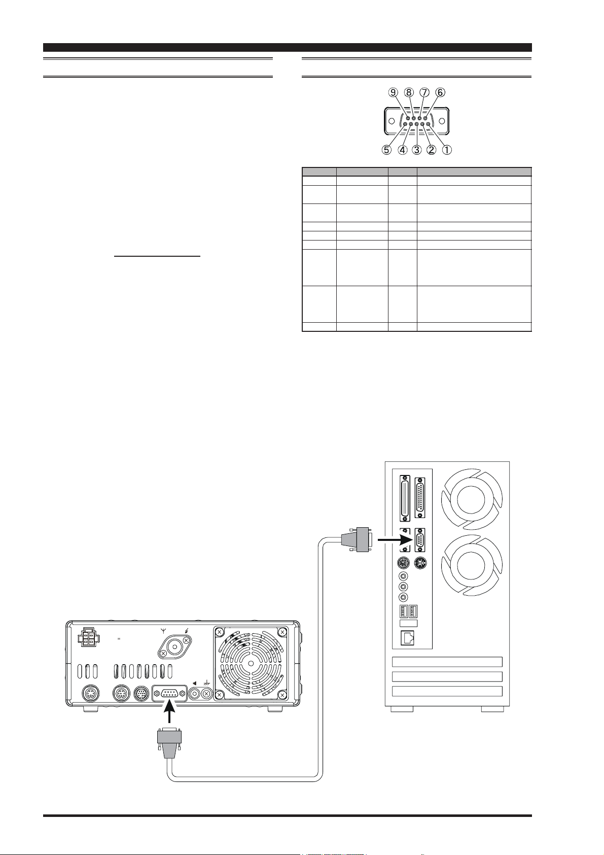
The FT-450 has a built-in level converter, allowing direct connection from the rear-panel CAT jack to the serial
port of your computer without the need of any external
boxes. You will need a serial cable for connection to the
RS-232C (serial or COM port) connector on your computer. Purchase a standard serial cable (not the so-called
“null modem” type), ensuring it has the correct gender
and number of pins (some serial COM port connectors
use a 9-pin rather than 25-pin configuration). If your computer uses a custom connector, you may have to construct
the cable. In this case, refer to the technical documentation supplied with your computer for correct data connection.
Vertex Standard does not produce CAT System operating
software due to the wide variety of personal computers
and operating systems in use today. However, the information provided in this chapter explains the serial data
structure and opcodes used by the CAT system. This information, along with the short programming examples,
is intended to help you start writing programs on your
own. As you become more familiar with CAT operation,
you can customize programs later on for your operating
needs and discover the true operating potential of this system.
PIN NO.
c
d
e
f
g
h
i
j
k
PIN NAME
N/A
SERIAL OUT
SERIAL IN
N/A
GND
N/A
RTS
CTS
N/A
CAT JACK
I/O
--Outputs the Serial Data from the
Output
transceiver to the computer.
Inputs the Serial Data from the
Input
computer to the transceiver.
---
---
--When the computer is not ready
Input
to receive data, this port goes “L”
to inhibit transmit data from the
transceiver.
When the transceiver is not ready
Output
to receive data, this port goes “L”
to inhibit the transmit data from
the computer.
---
FUNCTION
---
---
Signal Ground
---
---
Page 1
INPUT
DC 13.8V
22A
COM
ANT
EXT
GND
SPKR
CATLINEARTUNERDATA
CAT
RS-232C “Straight” Cable
FT-450 CAT OPERATION REFERENCE BOOK
Page 3

CAT
(
COMPUTER AIDED TRANSCEIVER
CONTROL COMMAND
)
OPERATION
A computer control command is composed of an alphabetical command, various parameters, and the terminator
that signals the end of the control command.
Example: Set the VFO-A frequency to 14.250000 MHz.
FA 14250000 ;
KKK
Command Parameter Terminator
There are three types of commands for the FT-450 as shown
below:
Set command: Set a particular condition
(to the FT-450)
Read command: Reads an answer
(from the FT-450)
Answer command: Transmits a condition
(from the FT-450)
For example, note the following in the case of the FA command (Set the VFO-A frequency):
To set the VFO-A frequency to 14.250000 MHz, the
following command is sent from the computer to the
transceiver:
“FA14250000;” (Set command)
To read the VFO-A frequency, the following command
is sent from the computer to the transceiver:
“FA; ” (Read command)
When the Read command above has been sent, the
following command is returned to the computer:
“FA14250000;” (Answer command)
Alphabetical Commands
A command consists of 2 alphabetical characters.
You may use either lower or upper case characters. The
commands available for this transceiver are listed in the
“PC Control Command Tables” on the following pages.
Parameters
Parameters are used to specify information necessary to
implement the desired command.
The parameters to be used for each command are predetermined. The number of digits assigned to each parameter is also predetermined. Refer to the “Control Command List” and the “Control Command Tables” to configure the appropriate parameters.
When configuring parameters, be careful not to make the
following mistakes.
For example, when correct parameter is “IS0+1000” (IF
SHIFT):
IS01000;
Not enough parameters specified (No direction (+)
given for the IF shift)
IS0+100;
Not enough digits (Only three frequency digits
given)
IS0_+_1000;
Unnecessary characters between parameters
IS0+10000;
Too many digits (Five frequency digits given)
Note: If a particular parameter is not applicable to the FT450, the parameter digits should be filled using any char-
acter except the ASCII control codes (00 to 1Fh) and the
terminator (;).
Terminator
To signal the end of a command, it is necessary to use a
semicolon (;). The digit where this special character must
appear differs depending on the command used.
FT-450 CAT OPERATION REFERENCE BOOK
Page 2
Page 4

CAT
C
OMMAND
ANTENNA TUNER CONTROL
AC
AF GAIN
AG
AUTO INFORMATION
AI
BAND DOWN
BD
BREAK-IN
BI
MANUAL NOTCH
BP
BAND SELECT
BS
BAND UP
BU
BUSY
BY
CHANNEL UP/DOWN
CH
CTCSS NUMBER
CN
CONTOUR
CO
CW SPOT
CS
CTCSS
CT
DIMMER
DA
MIC DOWN
DN
DIMMER SWITCH
DS
ENCODER DOWN
ED
ENCODER UP
EU
MENU
EX
FREQUENCY VFO-A
FA
FREQUENCY VFO-B
FB
FAST STEP
FS
FUNCTION TX
FT
AGC FUNCTION
GT
IDENTIFICATION
ID
INFORMATION
IF
IF-SHIFT
IS
KEYER MEMORY
KM
KEY PITCH
KP
KEYER
KR
KEY SPEED
KS
CW KEYING
KY
LOCK
LK
LOAD MESSEGE
LM
MEMORY CHANNEL
MC
MODE
MD
MIC GAIN
MG
MODE KEY
MK
MONITOR LEVEL
ML
MEMORY READ
MR
METER SW
MS
(
COMPUTER AIDED TRANSCEIVER
CONTROL COMMAND LIST
FUNCTION SET READ AI
O
O
O
O
O
O
O
O
X
O
O
O
O
O
O
O
O
O
O
O
O
O
O
O
O
X
X
O
O
O
O
O
O
O
O
O
O
O
O
O
X
O
ANS.
O
O
O
O
O
O
X
X
O
O
O
O
X
X
X
X
O
O
X
X
O
O
O
O
O
O
O
O
O
O
X
X
O
O
X
X
X
X
O
O
O
O
O
O
O
O
O
O
O
O
O
O
O
O
O
O
O
O
O
O
O
O
O
O
X
X
O
O
O
O
O
O
O
O
O
O
X
X
O
O
O
O
O
O
C
OMMAND
MEMORY WRITE
MW
O
NARROW
NA
O
NOISE BLANKER
NB
X
NOISE REDUCTION
NR
X
OPPOSITE BAND INFORMATION
OI
O
OFFSET (REPEATER SHIFT)
OS
O
PRE-AMP (IPO)
PA
X
PLAY BACK
PB
X
POWER CONTROL
PC
O
POWER SWITH
PS
X
QMB STORE
QI
O
QMB RECALL
QR
O
QUICK SPLIT
QS
O
RF ATTENUATOR
RA
O
CLAR CLEAR
RC
X
CLAR DOWN
RD
X
RF GAIN
RG
O
RADIO INFORMATION
RI
X
NOISE REDUCTION LEVEL
RL
X
READ METER
RM
O
RESET POWER ON
RP
O
RADIO STATUS
RS
O
CLAR
RT
O
CLAR UP
RU
O
SCAN
SC
O
SEMI BREAK-IN DELAY TIME
SD
X
WIDTH
SH
O
S METER
SM
O
SQUELCH LEVEL
SQ
X
STEP
ST
O
SWAP VFO
SV
O
TXW
TS
O
TX SET
TX
X
UNLOCK
UL
O
MIC UP
UP
X
VOX DELAY TIME
VD
X
VOX GAIN
VG
O
[
V/M] KEY FUNCTION
VM
O
VOICE
VR
X
VFO SELECT
VS
O
VFO TO VFO
VV
X
VOX
VX
O
)
OPERATION
FUNCTION SET READ AI
X
O
O
O
O
O
O
O
O
X
O
O
O
O
O
O
O
O
O
O
X
O
X
O
X
O
O
O
X
O
X
O
O
O
O
X
O
O
O
X
X
O
O
X
O
O
X
O
O
O
O
O
O
O
O
X
O
O
O
O
X
O
O
O
O
O
O
X
X
O
O
O
O
O
X
O
O
O
O
O
O
O
O
O
ANS.
X
O
O
O
O
O
O
O
O
O
X
X
X
O
X
X
O
O
O
O
X
O
O
X
O
O
O
O
O
O
X
O
O
O
X
O
O
X
O
O
O
O
X
O
O
O
X
O
O
X
O
X
X
X
X
O
X
X
O
O
O
O
X
O
O
X
O
O
O
O
O
O
X
O
O
O
X
O
O
X
X
O
O
O
Page 3
FT-450 CAT OPERATION REFERENCE BOOK
Page 5
CAT
(
COMPUTER AIDED TRANSCEIVER
CONTROL COMMAND TABLES
AA
CC
A
C ANTENNA TUNER CONTROL
AA
CC
Set 12345678910
Read 12345678910
Answer 12345678910
AA
GG
A
G AF GAIN
AA
GG
Set 12345678910
Read 12345678910
Answer 12345678910
AIAI
AI AUTO INFORMATION
AIAI
Set 12345678910
Read 12345678910
Answer 12345678910
BDBD
BD BAND DOWN
BDBD
Set 12345678910
Read 12345678910
ACP1 P2 P3 ;
AC ;
ACP1 P2 P3 ;
AGP1 P2 P2 P2 ;
AGP1 ;
AGP1 P2 P2 P2 ;
AIP1 ;
AI ;
AIP1 ;
BDP1 ;
)
OPERATION
P1 0: Fixed P3 0: Tuner “OFF”
P2 0: Fixed 1: Tuner “ON”
P1 0: Fixed
P2 000 - 255
P1 0: Auto Information “OFF”
1: Auto Information “ON”
This parameter is set to “0” (OFF) automatically when the transceiver is turned “OFF.”
P1 0: VFO-A
1: VFO-B
2: Tuning Start
Answer 12345678910
BIBI
BI BREAK-IN
BIBI
Set 12345678910
Read 12345678910
Answer 12345678910
BPBP
BP MANUAL NOTCH
BPBP
Set 12345678910
Read 12345678910
Answer 12345678910
BSBS
BS BAND SELECT
BSBS
Set 12345678910
Read 12345678910
Answer 12345678910
BB
UU
B
U BAND UP
BB
UU
Set 12345678910
Read 12345678910
BIP1 ;
BI ;
BIP1 ;
BPP1 P2 P3 P3 P3 ;
BPP1 P2 ;
BPP1 P2 P3 P3 P3 ;
BSP1 P1 ;
BUP1 ;
P1 0: Break-in “OFF”
1: Break-in “ON”
P1 0: Fixed
P2 0: Manual NOTCH “ON/OFF”
1: Manual NOTCH Position
P1 00: 1.8 MHz 06: 18 MHz
01: 3.5 MHz 07: 21 MHz
02: Invalid 08: 24.5 MHz
03: 7 MHz 09: 28 MHz
04: 10 MHz 10: 50 MHz
05: 14 MHz 11: GEN
P1 0: Fixed
P3 When P2=0
000: OFF
001: ON
When P2=1
001 - 199: NOTCH position move to left
200: NOTCH position move to center
201 - 400: NOTCH position move to right
Answer 12345678910
BYBY
BY BUSY
BYBY
Set 12345678910
Read 12345678910
BY ;
Answer 12345678910
BYP1 P2 ;
P1 0: BUSY “OFF”
1: BUSY “ON”
P2 0: Fixed
FT-450 CAT OPERATION REFERENCE BOOK
Page 4
Page 6
CAT
(
COMPUTER AIDED TRANSCEIVER
CONTROL COMMAND TABLES
CHCH
CH CHANNEL UP/DOWN
CHCH
Set 12345678910
Read 12345678910
Answer 12345678910
CNCN
CN CTCSS TONE FREQUENCY
CNCN
Set 12345678910
Read 12345678910
Answer 12345678910
COCO
CO CONTOUR
COCO
Set 12345678910
Read 12345678910
Answer 12345678910
CSCS
CS CW SPOT
CSCS
Set 12345678910
Read 12345678910
Answer 12345678910
CTCT
CT CTCSS
CTCT
Set 12345678910
Read 12345678910
Answer 12345678910
DD
AA
D
A DIMMER
DD
AA
Set 12345678910
Read 12345678910
Answer 12345678910
DNDN
DN MIC DWN
DNDN
Set 12345678910
Read 12345678910
CHP1 ;
CNP1 P2 P2 ;
CNP1 ;
CNP1 P2 P2 ;
COP1 P2 P3 P3 ;
COP1 P2 ;
COP1 P2 P3 P3 ;
CSP1 ;
CS ;
CSP1 ;
CTP1 P2 ;
CTP1 ;
CTP1 P2 ;
DAP1 P1 P2 P2 ;
DA ;
DAP1 P1 P2 P2 ;
DN ;
)
OPERATION
P1 0: Memory Channel “UP”
1: Memory Channel “DOWN”
P1 0: Fixed
P2 00 - 49: Tone Frequency Number (See Table 1)
P1 0: Fixed
P2 0: CONTOUR “ON/OFF”
1: CONTOUR Frequency
P1 0: OFF
1: ON
P1 0: Fixed
P2 0: CTCSS “OFF”
1: CTCSS ENC/DEC “ON”
2: CTCSS ENC “ON”
P1 00 - 04
P2 00: Fixed
P3 When P2=0,
-2: CONTOUR “ON” -12 dB
-1: CONTOUR “ON” -6 dB
00: CONTOUR “OFF”
+1: CONTOUR “ON” +6 dB
+2: CONTOUR “ON” +12 dB
When P2=1,
01 ~ 07: 250 Hz
08 ~ 13: 500 Hz
14 ~ 19: 1 kHz
20 ~ 25: 2 kHz
26 ~ 32: 4 kHz
Answer 12345678910
DSDS
DS DIMMER SWITCH
DSDS
Set 12345678910
DSP1 ;
Read 12345678910
DS ;
Answer 12345678910
DSP1 ;
00
67.0 Hz
01
69.3 Hz
02
71.9 Hz
03
74.4 Hz
04
77.0 Hz
05
79.7 Hz
06
82.5 Hz
07
85.4 Hz
08
88.5 Hz
09
10
11
12
13
14
15
16
17
91.5 Hz
94.8 Hz
97.4 Hz
100.0 Hz
103.5 Hz
107.2 Hz
110.9 Hz
114.8 Hz
118.8 Hz
18
19
20
21
22
23
24
25
26
Page 5
P1 0: DIMMER “OFF”
1: DIMMER “ON”
TABLE 1
CTCSS TONE CHART
123.0 Hz
127.3 Hz
131.8 Hz
136.5 Hz
141.3 Hz
146.2 Hz
151.4 Hz
156.7 Hz
159.8 Hz
27
28
29
30
31
32
33
34
35
FT-450 CAT OPERATION REFERENCE BOOK
162.2 Hz
165.5 Hz
167.9 Hz
171.3 Hz
173.8 Hz
177.3 Hz
179.9 Hz
183.5 Hz
186.2 Hz
36
37
38
39
40
41
42
43
44
189.9 Hz
192.8 Hz
196.6 Hz
199.5 Hz
203.5 Hz
206.5 Hz
210.7 Hz
218.1 Hz
225.7 Hz
45
46
47
48
49
---
---
---
---
229.1 Hz
233.6 Hz
241.8 Hz
250.3 Hz
254.1 Hz
---
---
---
---
Page 7

CAT
(
COMPUTER AIDED TRANSCEIVER
CONTROL COMMAND TABLES
EDED
ED ENCODER DOWN
EDED
Set 12345678910
Read 12345678910
Answer 12345678910
EUEU
EU ENCODER UP
EUEU
Set 12345678910
Read 12345678910
Answer 12345678910
EDP1 P2 P2 ;
EUP1 P2 P2 ;
P1 0:Fixed
P2 01-99: Steps
P1 0:Fixed
P2 01-99: Steps
)
OPERATION
FT-450 CAT OPERATION REFERENCE BOOK
Page 6
Page 8

CAT
(
COMPUTER AIDED TRANSCEIVER
CONTROL COMMAND TABLES
EXEX
EX MENU
EXEX
Set 12345678nn
EXP1 P1 P1 P2 P2 ~ P2 ;
Read 12345678910
EXP1 P1 P1 ;
Answer 12345678nn
EXP1 P1 P1 P2 P2 ~ P2 ;
FUNCTION
P1
EXT MNU
001
AM & FMDIAL
002
APO TIME
003
BEACON TIME
004
BEACON TEXT
005
BEEP TONE
006
BEEPVOL
007
CAT RTS
008
CAT TIME OUT TIME
009
CATRATE
010
CLAR DIAL / SEL
011
CLOCK SHIFT
012
DISP CONTRAST
013
CW AUTO MODE
014
CW BFO
015
CW DELAY
016
CW KEY REVERSE
017
CW QSK
018
CW PADDLE
019
CWPITCH
020
CWSPEED
021
CW SIDE TONE
022
CW TRAINING
023
CW WEIGHT
024
DATA DISP
025
DATA MODE
026
Not Used
027
Not Used
028
DIAL STEP
029
DIG VOX
030
EMERGENCY
031
KEY HOLD TIME
032
LOCK MODE
033
M-TUNE
034
MEMORY GROUP
035
MEMORY TAG
036
MIC EQ
037
MIC GAIN
038
MIC AUTO SCAN
039
MY BAND
040
MY MODE
041
MIC-DOWN PG
042
MIC-FAST PG
043
MIC-UP PG
044
METER PEAK HOLD
045
PANEL’S CUSTOM SWITCH
046
QUICK SPLIT FREQ
047
RF POWER SET
048
REPEATER SHIFT DIRECTION
049
REPEATER SHIFT OFFSET
050
RTTY SHIFT
051
RTTY TONE
052
RTTY RX POLARITY
053
RTTY TX POLARITY
054
SCAN RESUME
055
SEL DIAL MODE
056
SQL TYPE
057
SQL/RF GAIN
058
STBY BEEP
059
TONE FREQ
060
TOT TIME
061
TUNER/ATAS
062
VOX DELAY
063
VOXGAIN
064
P2
0: OFF 1: ON
0: DISABLE 1: ENABLE
00 (OFF) ~ 01 (hour) ~ 12 (hour)
000 (OFF) ~ 001 (sec) ~ 255 (sec)
- - 0: 440 Hz 1: 880 Hz 2: 1760 Hz
000 (FIX 0) ~ 100 (FIX100) or 101 (LNK-50) ~ 151 (LNK0) ~ 201 (LNK+50)
0: DISABLE 1: ENABLE
0: 10 msec 1: 100 msec 2: 1000 msec 3: 3000 msec
1: 4800 bps 2: 9600 bps 3: 19200 bps 4: 38400 bps 5: DATA
0: DIAL 1: SEL
0: OFF 1: ON
01 ~ 24
0: OFF 1: ON
0: USB 1: LSB 2: AUTO
0000 (FULL) / 0030 (msec) ~ 3000 (msec)
0: NORMAL 1: REVERSE
0: 15 msec 1: 20 msec 2: 25 msec 3: 30 msec
0: KEY 1: MIC
00 - 02: 400 Hz 03 - 04: 500 Hz 05 - 06: 600 Hz 07 - 08: 700 Hz 09 - 15: 800 Hz
04 (wpm) ~ 60 (wpm)
000 (FIX 0) ~ 100 (FIX100) or 101 (LNK-50) ~ 151 (LNK0) ~ 201 (LNK+50)
0: N (Numeric Character Only) 1: A (Alphabet Character Only) 2: M (Mixed: Numeric and Alphabet Character)
25 (1:2.5) ~ 45 (1:4.5)
-300 (-3000 Hz) ~ +000 (0 Hz) ~ +300 (+3000 Hz)
0: RTTY 1: USER-L 2: USER-U
---
--0: 1 Hz 1: 10 Hz 2: 20 Hz 3: 100 Hz 4: 200 Hz
000 (OFF) ~ 100
0: OFF 1: ON
0: 0.5 sec 1: 1.0 sec 2: 1.5 sec 3: 2.0 sec
0: FREQ 1: PANEL 2: ALL
0: OFF 1: ON
0: OFF 1: ON
0: TAG-OFF 1: TAG NAME
0 ~ 9
0: LOW 1: NOR 2: HIGH
0: OFF 1: ON
See Table 3
See Table 4
See Table 5
See Table 5
See Table 5
0: OFF 1: ON
See Table 5
-20 (kHz) ~ +00 (kHz) ~ +20 (kHz)
005 ~ 100
0: SIMPLEX 1: +SHIFT 2: - SHIFT
000 (0 MHz) ~ 999 (99.9 MHz)
1: 170 Hz 2: 200 Hz 3: 425 Hz 4: 850 Hz
1: 1275 Hz 2: 2125 Hz
0: NORMAL 1: REVERSE
0: NORMAL 1: REVERSE
00: BUSY 01 (TIME: 1 sec) ~ 10 (TIME: 10 sec)
0: CW Sidetone Level 1: CW KEYER Speed 2: 100KHz Step 3: 1MHz Step 4: MIC GAIN Set 5: RF Power Set
0: OFF 1: ENC 2: ENC DEC
0: SQL 1: RF GAIN
0: OFF 1: ON
See Table 6
00 (OFF) ~ 01 (minute) ~ 20 (minute)
0: ATAS 1: EXT ATU 2: INT ATU 3: INTRATU 4: F TRANS
01 (100 msec) ~ 30 (300 msec)
001 ~ 255
**
**
P1 001-064 (MENU Number)
P2 Parameter (See Table 2)
TABLE 2
)
OPERATION
Page 7
FT-450 CAT OPERATION REFERENCE BOOK
Page 9

CAT
(
COMPUTER AIDED TRANSCEIVER
CONTROL COMMAND TABLES
)
OPERATION
P2
000
001
003
004
005
006
007
008
009
010
FUNCTION
1.8 MHz “OFF”
3.5 MHz “OFF”
7 MHz “OFF”
10 MHz “OFF”
14 MHz “OFF”
18 MHz “OFF”
21 MHz “OFF”
24.5 MHz “OFF”
28 MHz “OFF”
50 MHz “OFF”
TABLE 3
MY BAND
P2
100
101
103
104
105
106
107
108
109
110
FUNCTION
1.8 MHz “ON”
3.5 MHz “ON”
7 MHz “ON”
10 MHz “ON”
14 MHz “ON”
18 MHz “ON”
21 MHz “ON”
24.5 MHz “ON”
28 MHz “ON”
50 MHz “ON”
P2
FUNCTION
01
02
03
04
05
06
DATA (RTTY-LSB) “OFF”
07
08
09
DATA (RTTY-USB) “OFF”
0A
0B
0C
USER-U “OFF”
TABLE 4
MY MODE
LSB “OFF”
USB “OFF”
CW “OFF”
FM “OFF”
AM “OFF”
CW-R “OFF”
USER-L “OFF”
N.A.
FM-N “OFF”
P2
FUNCTION
11
12
13
14
15
16
DATA (RTTY-LSB) “ON”
17
18
19
DATA (RTTY-USB) “ON”
1A
1B
1C
TABLE 5
P2 FUNCTION
01 MONI Activates the Monitor function.
02 N/A No Function.
03 P/B Activates the Digital Voice Recorder.
04 PLAY1 Send the CW message, which is memorized in BEACON TEXT 1.
05 PLAY2 Send the CW message, which is memorized in BEACON TEXT 2.
06 PLAY3 Send the CW message, which is memorized in BEACON TEXT 3.
07 QSPL Activates Quick Split Operation
08 SPOT Generates a CW Spot Tone when using CW mode.
09 SQLOFF Opens the noise squelch.
10 SWR Transmits a 10 watts carrier (CW mode) to measure the SWR ratio.
11 TXW Monitor the transmit frequency when Split Frequency operation is engaged.
12 VCC Display the DC supply voltage.
13 VOICE2 Announces the current S-meter reading, operating frequency (with resolution to the displayed 100 Hz digit), and operating mode.
14 VM1MONI Play back the voice message, which is memorized in Voice Memory 1.
15 VM1REC Store the voice message into Voice Memory 1.
16 VM1TX Send the voice message, which is memorized in Voice Memory 1.
17 VM2MONI Play back the voice message, which is memorized in Voice Memory 2.
18 VM2REC Store the voice message into Voice Memory 2.
19 VM2TX Send the voice message, which is memorized in Voice Memory 2.
20 DOWN Decreases the VFO frequency by one step or moves the memory channel to the next-lowest channel.
21 FAST Set to the same function as the front panel’s [FAST] button.
22 UP Increases the VFO frequency by one step or moves the memory channel to the next-highest channel.
23 DSP Set to the same function as the front panel’s [DSP] button.
24 ATT/IPO Set to the same function as the front panel’s [ATT/IPO] button.
25 NB Set to the same function as the front panel’s [NB] button.
26 AGC Set to the same function as the front panel’s [AGC] button.
27 MODEDN Set to the same function as the front panel’s [MODET] button.
28 MODEUP Set to the same function as the front panel’s [MODES] button.
29 DSP/SEL Set to the same function as the front panel’s [DSP/SEL] button.
30 KEYER Set to the same function as the front panel’s [KEYER] button.
31 CLAR Set to the same function as the front panel’s [CLAR] button.
32 BANDDN Set to the same function as the front panel’s [BANDT] button.
33 BANDUP Set to the same function as the front panel’s [BANDS] button.
34 A=B Set to the same function as the front panel’s [A=B] button.
35 A/B Set to the same function as the front panel’s [A/B] button.
36 LOCK Set to the same function as the front panel’s [LOCK] button.
37 TUNE Set to the same function as the front panel’s [TUNE] button.
38 VOICE Announce the current operating frequency (with resolution to the displayed 100 Hz digit) and operating mode.
39 MW Copies the current operating data from the VFO into the currently selected memory channel.
40 V/M Toggles frequency control between VFO and memory system.
41 HOME Recall the “Home” (favorite frequency) channel.
42 RCL Recall the QMB (Quick Memory Bank) memory.
43 VOX Activate the VOX (automatic voice-actuated transmitter switching) feature.
44 STO Copies operating data into QMB (Quick Memory Bank) Memory.
45 STEP Enables the setting of the frequency step of the [DSP/SEL] knob by the [DSP/SEL] knob.
46 SPLIT Activates split frequency operation between VFO-A and VFO-B.
47 PMS Engages Programmable Memory Scan (PMS).
48 SCAN Initiates the upward scanning of VFO frequencies or memory channels.
49 MENU Engage the “Menu” mode.
50 DIMMER Enables adjustment of the display dimmer level by the [DSP/SEL] knob.
51 MTR Change the meter function in the transmit mode.
LSB “ON”
USB “ON”
CW “ON”
FM “ON”
AM “ON”
CW-R “ON”
USER-L “ON”
N.A.
FM-N “ON”
USER-U “ON”
00
67.0 Hz
01
69.3 Hz
02
71.9 Hz
03
74.4 Hz
04
77.0 Hz
05
79.7 Hz
06
82.5 Hz
07
85.4 Hz
08
88.5 Hz
09
91.5 Hz
10
94.8 Hz
11
97.4 Hz
12
100.0 Hz
13
103.5 Hz
14
107.2 Hz
15
110.9 Hz
16
114.8 Hz
17
118.8 Hz
123.0 Hz
18
127.3 Hz
19
131.8 Hz
20
136.5 Hz
21
141.3 Hz
22
146.2 Hz
23
151.4 Hz
24
156.7 Hz
25
159.8 Hz
26
FT-450 CAT OPERATION REFERENCE BOOK
CTCSS TONE CHART
TABLE 6
27
162.2 Hz
28
165.5 Hz
29
167.9 Hz
30
171.3 Hz
31
173.8 Hz
32
177.3 Hz
33
179.9 Hz
34
183.5 Hz
35
186.2 Hz
36
189.9 Hz
37
192.8 Hz
38
196.6 Hz
39
199.5 Hz
40
203.5 Hz
41
206.5 Hz
42
210.7 Hz
43
218.1 Hz
44
225.7 Hz
45
229.1 Hz
46
233.6 Hz
47
241.8 Hz
48
250.3 Hz
49
254.1 Hz
---
---
---
---
---
---
---
---
Page 8
Page 10

CAT
(
COMPUTER AIDED TRANSCEIVER
CONTROL COMMAND TABLES
FF
AA
F
A FREQUENCY VFO-A
FF
AA
Set 12345678910
FAP1 P1 P1 P1 P1 P1 P1 P1
11 12 13 14 15 16 17 18 19 20
Read 12345678910
Answer 12345678910
FBFB
FB FREQUENCY VFO-B
FBFB
Set 12345678910
Read 12345678910
Answer 12345678910
FSFS
FS FAST STEP
FSFS
Set 12345678910
Read 12345678910
Answer 12345678910
FTFT
FT FUNCTION TX
FTFT
Set 12345678910
Read 12345678910
Answer 12345678910
GTGT
GT AGC FUNCTION
GTGT
Set 12345678910
Read 12345678910
Answer 12345678910
IDID
ID IDENTIFICATION
IDID
Set 12345678910
;
FA ;
FAP1 P1 P1 P1 P1 P1 P1 P1
11 12 13 14 15 16 17 18 19 20
;
FBP1 P1 P1 P1 P1 P1 P1 P1
11 12 13 14 15 16 17 18 19 20
;
FB ;
FBP1 P1 P1 P1 P1 P1 P1 P1
11 12 13 14 15 16 17 18 19 20
;
FSP1 ;
FS ;
FSP1 ;
FTP1 ;
FT ;
FTP1 ;
GTP1 P2 ;
GTP1 ;
GTP1 P2 ;
)
OPERATION
P1 30000 - 60000000 (Hz)
P1 300000 - 60000000 (Hz)
P1 0: FAST Key “OFF”
1: FAST Key “ON”
P1 0: Transmit the Displayed Band
1: Transmit the Opposite Band
P1 0: Fixed P2 0: AGC “OFF”
P1 0241 (Fixed value)
1: AGC “FAST”
2: AGC “SLOW”
3: AGC “SLOW”
4: AGC “AUTO”
Read 12345678910
Answer 12345678910
IFIF
IF INFORMATION
IFIF
Set 12345678910
Read 12345678910
Answer 12345678910
ID;
IDP1 P1 P1 P1 ;
IF;
IFP1 P1 P1 P2 P2 P2 P2 P2
11 12 13 14 15 16 17 18 19 20
P2 P2 P2 P3 P3 P3 P3 P3 P4 P5
21 22 23 24 25 26 27 28 29 30
P6 P7 P8 P9 P9 P10 ;
Page 9
P1 000-510 (Memory Channel) P2 VFO-A Frequency (Hz)
P3 Clarifier Direction +: Plus Shift, --: Minus Shift
Clarifier Offset: 0000 - 9999 (Hz)
P4 0: RX CLAR “OFF” 1: RX CLAR “ON”
P5 0: TX CLAR “OFF” 1: TX CLAR “ON”
P6 MODE 1: LSB 2: USB 3: CW 4: FM 5: AM 6: DATA (RTTY-LSB)
P7 0: VFO 1: Memory 2: Memory Tune 3: Quick Memory Bank (QMB)
P8 0: CTCSS “OFF” 1: CTCSS ENC/DEC 2: CTCSS ENC
P9 Tone Number (See Table 1)
P10 0: Simplex 1: Plus Shift 2: Minus Shift
7: CW-R 8: USER-L 9: DATA (RTTY-USB)
B: FM-N C: USER-U
FT-450 CAT OPERATION REFERENCE BOOK
Page 11

CAT
(
COMPUTER AIDED TRANSCEIVER
CONTROL COMMAND TABLES
ISIS
IS IF-SHIFT
ISIS
Set 12345678910
Read 12345678910
Answer 12345678910
KMKM
KM KEYER MEMORY
KMKM
Set 1234567~43
Read 12345678910
Answer 1234567~43
KPKP
KP KEY PITCH
KPKP
Set 12345678910
Read 12345678910
Answer 12345678910
KRKR
KR KEYER
KRKR
Set 12345678910
Read 12345678910
Answer 12345678910
KSKS
KS KEY SPEED
KSKS
Set 12345678910
Read 12345678910
Answer 12345678910
KYKY
KY CW KEYING
KYKY
Set 12345678910
Read 12345678910
ISP1 -/+ P2 P2 P2 P2 ;
ISP1 ;
ISP1 -/+ P2 P2 P2 P2 ;
KMP1 P2 P2 P2 P2 ~ P2 ;
KMP1 ;
KMP1 P2 P2 P2 P2 ~ P2 ;
KPP1 P1 ;
KP ;
KPP1 P1 ;
KRP1 ;
KR ;
KRP1 ;
KSP1 P1 P1 ;
KS ;
KSP1 P1 P1 ;
KYP1 ;
**
**
P1 0: Fixed
P2 0000 ~ 1000 (Hz)
P1 1 - 3 : Beacon Text Channel Number
P2 Message Characters (up to 40 characters)
P1 02: 400 Hz
04: 500 Hz
06: 600 Hz
08: 700 Hz
10: 800 Hz
P1 0: KEYER “OFF”
1: KEYER “ON”
P1 004 - 060 (WPM)
P1 6: Beacon Text “1” Playback
7: Beacon Text “2” Playback
8: Beacon Text “3” Playback
)
OPERATION
Answer 12345678910
LKLK
LK LOCK
LKLK
Set 12345678910
Read 12345678910
Answer 12345678910
LMLM
LM LOAD MESSEGE
LMLM
Set 12345678910
Read 12345678910
Answer 12345678910
MCMC
MC MEMORY CHANNEL
MCMC
Set 12345678910
Read 12345678910
Answer 12345678910
LKP1 ;
LK ;
LKP1 ;
LMP1 P2 ;
LMP1 ;
LMP1 P2 ;
MCP1 P1 P1 ;
MC ;
MCP1 P1 P1 ;
P1 0: DIAL Lock “OFF”
1: DIAL Lock “ON”
P1 0: VOICE MEMORY
1: DIGITAL VOICE RECORDER
P1 001 - 504: Memory Channel Number
001 - 500: Regular Memory Channel
501: P1L Channel
502: P1U Channel
503: P2L Channel
504: P2U Channel
P2 When P1=0
0: VOICE MEMORY RECORDING STOP
1: VOICE MEMORY 1 RECORDING
2: VOICE MEMORY 2 RECORDING
When P1=1
0: DIGITAL VOICE RECORDER STOP
1: DIGITAL VOICE RECORDER START
FT-450 CAT OPERATION REFERENCE BOOK
Page 10
Page 12

CAT
(
COMPUTER AIDED TRANSCEIVER
CONTROL COMMAND TABLES
MDMD
MD OPERATING MODE
MDMD
Set 12345678910
Read 12345678910
Answer 12345678910
MGMG
MG MIC GAIN
MGMG
Set 12345678910
Read 12345678910
Answer 12345678910
MKMK
MK MODE KEY
MKMK
Set 12345678910
Read 12345678910
Answer 12345678910
MLML
ML MONITOR LEVEL
MLML
Set 12345678910
Read 12345678910
Answer 12345678910
MRMR
MR MEMORY CHANNEL READ
MRMR
Set 12345678910
Read 12345678910
Answer 12345678910
MDP1 P2 ;
MDP1 ;
MDP1 P2 ;
MGP1 P1 P1 ;
MG ;
MGP1 P1 P1 ;
MKP1 ;
MLP1 P2 P2 P2 ;
MLP1 ;
MLP1 P2 P2 P2 ;
MRP1 P1 P1 ;
MRP1 P1 P1 P2 P2 P2 P2 P2
11 12 13 14 15 16 17 18 19 20
P2 P2 P2 P3 P3 P3 P3 P3 P4 P5
21 22 23 24 25 26 27 28 29 30
P6 P7 P8 P9 P9 P10 ;
)
OPERATION
P1 0: Fixed
P2 MODE 1: LSB 2: USB 3: CW 4: FM 5: AM 6: DATA (RTTY-LSB)
P1 000 - 085: MIC GAIN “L”
P1 KEY 7: MODE UP
P1 0: Fixed
P2 000: MONITOR “OFF”
P1 Memory Channel Number P2 Memory Channel Frequency (Hz)
P3 Clarifier Direction +: Plus Shift, --: Minus Shift
P4 0: RX CLAR “OFF” 1: RX CLAR “ON”
P5 0: TX CLAR “OFF” 1: TX CLAR “ON”
P6 MODE 1: LSB 2: USB 3: CW 4: FM 5: AM 6: DATA (RTTY-LSB)
P7 0: VFO 1: Memory
P8 0: CTCSS “OFF” 1: CTCSS ENC/DEC 2: CTCSS ENC
P9: Tone Number (See Table 1)
P10 0: Simplex 1: Plus Shift 2: Minus Shift
7: CW-R 8: USER-L 9: DATA (RTTY-USB)
B: FM-N C: USER-U
086 - 170: MIC GAIN “M”
171 - 255: MIC GAIN “H”
8: MODE DOWN
9: REVERSE (@CW MODE)
001: MONITOR “ON”
Clarifier Offset: 0000 - 9999 (Hz)
7: CW-R 8: USER-L 9: DATA (RTTY-USB)
B: FM-N C: USER-U
MSMS
MS METER SW
MSMS
Set 12345678910
Read 12345678910
Answer 12345678910
MWMW
MW MEMORY CHANNEL WRITE
MWMW
Set 12345678910
Read 12345678910
Answer 12345678910
NN
AA
N
A NARROW
NN
AA
Set 12345678910
Read 12345678910
Answer 12345678910
MSP1 ;
MS ;
MSP1 ;
MWP1 P1 P1 P2 P2 P2 P2 P2
11 12 13 14 15 16 17 18 19 20
P2 P2 P2 P3 P3 P3 P3 P3 P4 P5
21 22 23 24 25 26 27 28 29 30
P6 P7 P8 P9 P9 P10 ;
MAP1 P2 ;
NAP1 ;
NAP1 P2 ;
P1 1: ALC
2: PO
3: SWR
P1 Memory Channel Number P2 Memory Channel Frequency (Hz)
P3 Clarifier Direction +: Plus Shift, --: Minus Shift
Clarifier Offset: 0000 - 9999 (Hz)
P4 0: RX CLAR “OFF” 1: RX CLAR “ON”
P5 0: TX CLAR “OFF” 1: TX CLAR “ON”
P6 MODE 1: LSB 2: USB 3: CW 4: FM 5: AM 6: DATA (RTTY-LSB)
P7 0: Fixed
P8 0: CTCSS “OFF” 1: CTCSS ENC/DEC 2: CTCSS ENC
P9: Tone Number (See Table 1)
P10 0: Simplex 1: Plus Shift 2: Minus Shift
P1 0: Fixed
P2 0: Bandwidth Middeum
7: CW-R 8: USER-L 9: DATA (RTTY-USB)
B: FM-N C: USER-U
1: Bandwidth Narrow
Page 11
FT-450 CAT OPERATION REFERENCE BOOK
Page 13

CAT
(
COMPUTER AIDED TRANSCEIVER
CONTROL COMMAND TABLES
NBNB
NB NOISE BLANKER STATUS
NBNB
Set 12345678910
Read 12345678910
Answer 12345678910
NRNR
NR NOISE REDUCTION
NRNR
Set 12345678910
Read 12345678910
Answer 12345678910
OIOI
OI OPPOSITE BAND INFORMATION
OIOI
Set 12345678910
Read 12345678910
Answer 12345678910
OSOS
OS OFFSET (REPEATER SHIFT)
OSOS
Set 12345678910
Read 12345678910
Answer 12345678910
PP
AA
P
A PRE-AMP (IPO)
PP
AA
Set 12345678910
Read 12345678910
Answer 12345678910
PBPB
PB PLAY BACK
PBPB
Set 12345678910
Read 12345678910
Answer 12345678910
PCPC
PC POWER CONTROL
PCPC
Set 12345678910
Read 12345678910
Answer 12345678910
PSPS
PS POWER SWITCH
PSPS
Set 12345678910
Read 12345678910
Answer 12345678910
NBP1 P2 ;
NBP1 ;
NBP1 P2 ;
NRP1 P2 ;
NRP1 ;
NRP1 P2 ;
OI ;
OIP1 P1 P1 P2 P2 P2 P2 P2
11 12 13 14 15 16 17 18 19 20
P2 P2 P2 P3 P3 P3 P3 P3 P4 P5
21 22 23 24 25 26 27 28 29 30
P6 P7 P8 P9 P9 P10 ;
OSP1 P2 ;
OSP1 ;
OSP1 P2 ;
PAP1 P2 ;
PAP1 ;
PAP1 P2 ;
PBP1 ;
PB ;
PBP1 ;
PCP1 P1 P1 ;
PC ;
PCP1 P1 P1 ;
PSP1 ;
PS ;
PSP1 ;
)
OPERATION
P1 0: Fixed
P2 0: Noise Blanker “OFF”
1: Noise Blanker “ON”
P1 0: Fixed
P2 0: Noise Reduction “OFF”
1: Noise Reduction “ON”
P1 Current Memory Channel P2 VFO-B Frequency (Hz)
P3 Clarifier Direction +: Plus Shift, --: Minus Shift
Crarifier Offset: 0000 - 9999 (Hz)
P4 0: RX CLAR “OFF” 1: RX CLAR “ON”
P5 0: TX CLAR “OFF” 1: TX CLAR “ON”
P6 MODE 1: LSB 2: USB 3: CW 4: FM 5: AM 6: DATA (RTTY-LSB)
P7 0: VFO 1: Memory 2: Memory Tune 3: Quick Memory Bank (QMB)
P8 0: CTCSS “OFF” 1: CTCSS ENC/DEC 2: CTCSS ENC
P9: Tone Number (See Table 1)
P10 0: Simplex 1: Plus Shift 2: Minus Shift
P1 0: Fixed
P2 0: Simplex
: FM mode only
ÚÚ
Ú
ÚÚ
P1 0: Fixed
P2 0: IPO “ON”
P1 0: STOP
P1 000 - 255
P1 0: POWER “OFF”
7: CW-R 8: USER-L 9: DATA (RTTY-USB)
B: FM-N C: USER-U
1: Plus Shift
2: Minus Shift
1: IPO “OFF”
1: VOICE MEMORY 1 PLAYBACK
2: VOICE MEMORY 2 PLAYBACK
6: DIGITAL VOICE RECODER PLAYBACK
1: POWER “ON”
This command requires dummy data be initially sent. Then after one second and
before two seconds the command is sent.
FT-450 CAT OPERATION REFERENCE BOOK
Page 12
Page 14

CAT
(
COMPUTER AIDED TRANSCEIVER
CONTROL COMMAND TABLES
QIQI
QI QMB STORE
QIQI
Set 12345678910
Read 12345678910
Answer 12345678910
QRQR
QR QMB RECALL
QRQR
Set 12345678910
Read 12345678910
Answer 12345678910
QSQS
QS QUICK SPLIT
QSQS
Set 12345678910
Read 12345678910
Answer 12345678910
RARA
RA RF ATTENUATOR
RARA
Set 12345678910
Read 12345678910
Answer 12345678910
RR
CC
R
C CLAR CLEAR
RR
CC
Set 12345678910
Read 12345678910
QI ;
QR ;
QS ;
RAP1 P2 ;
RAP1 ;
RAP1 P2 ;
RC ;
P1 0: Fixed
P2 0: OFF
1: ON
)
OPERATION
Answer 12345678910
RDRD
RD CLARIFIER MINUS OFFSET
RDRD
Set 12345678910
Read 12345678910
Answer 12345678910
RR
GG
R
G RF GAIN
RR
GG
Set 12345678910
Read 12345678910
Answer 12345678910
RIRI
RI RADIO INFORMATION
RIRI
Set 12345678910
Read 12345678910
Answer 12345678910
RLRL
RL NOISE REDUCTION LEVEL
RLRL
Set 12345678910
Read 12345678910
Answer 12345678910
RDP1 P1 P1 P1 ;
RGP1 P2 P2 P2 ;
RGP1 ;
RGP1 P2 P2 P2 ;
RIP1 ;
RIP1 P2 ;
RLP1 P2 P2 ;
RLP1 ;
RLP1 P2 P2 ;
P1 0000 - 9999 (Hz)
P1 0: Fixed
P2 000 - 255
P1 0: Hi-SWR
1: MIC-EQ
3: REC
4: PLAY
P2 0: OFF
1: ON
P1 0: Fixed
P2 01 - 11
Page 13
FT-450 CAT OPERATION REFERENCE BOOK
Page 15

CAT
(
COMPUTER AIDED TRANSCEIVER
CONTROL COMMAND TABLES
RMRM
RM READ METER
RMRM
Set 12345678910
Read 12345678910
Answer 12345678910
RPRP
RP RESET POWER ON
RPRP
Set 12345678910
Read 12345678910
Answer 12345678910
RSRS
RS RADIO STATUS
RSRS
Set 12345678910
Read 12345678910
Answer 12345678910
RR
TT
R
T CLAR
RR
TT
Set 12345678910
Read 12345678910
Answer 12345678910
RR
UU
R
U CLARIFIER PLUS OFFSET
RR
UU
Set 12345678910
Read 12345678910
RMP1 ;
RMP1 P2 P2 P2 ;
RP ;
RP ;
RP ;
RS ;
RSP1 ;
RTP1 ;
RT ;
RTP1 ;
RUP1 P1 P1 P1 ;
)
OPERATION
P1 0: Depends of the Front Panel’s METER Switch
1: S Meter
4: ALC Meter
5: PO Meter
6: SWR Meter
P2 000 - 255
Resetting the Microprocessor (Full Reset)
P1 0: NORMAL MODE
1: MENU MODE
P1 0: RX Clarifier “OFF”
1: RX Clarifier “ON”
P1 0000 - 9999 (Hz)
Answer 12345678910
SCSC
SC SCAN
SCSC
Set 12345678910
Read 12345678910
Answer 12345678910
SDSD
SD CW BREAK-IN DELAY TIME
SDSD
Set 12345678910
Read 12345678910
Answer 12345678910
SHSH
SH WIDTH
SHSH
Set 12345678910
Read 12345678910
Answer 12345678910
SMSM
SM S-METER READING
SMSM
Set 12345678910
Read 12345678910
Answer 12345678910
SCP1 ;
SC ;
SCP1 ;
SDP1 P1 P1 P1 ;
SD ;
SDP1 P1 P1 P1 ;
SHP1 P2 P2 ;
SHP1 ;
SHP1 P3 P3 ;
SMP1 ;
SMP1 P2 P2 P2 ;
P1 0: Scan “OFF”
1: Scan “ON” (Upward)
2: Scan “ON” (Downward)
P1 0000: Full Break-in
0030 - 3000 (msec)
P1 0:Fixed
P2 00 - 10 (Narrow)
11 - 21 (Normal)
22 - 31 (Wide)
P3 00 (Narrow)
16 (Normal)
31 (Wide)
P1 0: Fixed
P2 000 - 255
FT-450 CAT OPERATION REFERENCE BOOK
Page 14
Page 16

CAT
(
COMPUTER AIDED TRANSCEIVER
CONTROL COMMAND TABLES
SQSQ
SQ SQUELCLH LEVEL
SQSQ
Set 12345678910
Read 12345678910
Answer 12345678910
STST
ST STEP
STST
Set 12345678910
Read 12345678910
Answer 12345678910
SVSV
SV SWAP VFO
SVSV
Set 12345678910
Read 12345678910
Answer 12345678910
TSTS
TS TXW
TSTS
Set 12345678910
Read 12345678910
Answer 12345678910
TXTX
TX TX SET
TXTX
Set 12345678910
Read 12345678910
Answer 12345678910
ULUL
UL PLL UNLOCK STATUS
ULUL
Set 12345678910
Read 12345678910
Answer 12345678910
UPUP
UP MIC UP
UPUP
Set 12345678910
Read 12345678910
SQP1 P2 P2 P2 ;
SQP1 ;
SQP1 P2 P2 P2 ;
STP1 ;
ST ;
STP1 ;
SV ;
TSP1 ;
TS ;
TSP1 ;
TXP1 ;
TX ;
TXP1 ;
UL ;
ULP1 ;
UP ;
)
OPERATION
P1 0: Fixed
P2 000 - 255
FM AM LSB/USB/CW
P1 0: 5.0 kHz 2.5 kHz 1.0 kHz
1: 6.25 kHz 5.0 kHz 2.5 kHz
2: 10.0 kHz 9.0 kHz 5.0 kHz
3: 12.5 kHz 10.0 kHz
4: 15.0 kHz 12.5 kHz
5: 20.0 kHz 25.0 kHz
P1 0: TXW “OFF”
1: TXW “ON”
P1 0: RADIO TX “OFF” CAT TX “OFF”
1: RADIO TX “OFF” CAT TX “ON”
2: RADIO TX “ON” CAT TX “OFF” (Answer)
P1 0: PLL “Lock”
1: PLL “Unlock”
FM
P1 6: 25.0 kHz
7: 50.0 kHz
Answer 12345678910
VDVD
VD VOX DELAY TIME
VDVD
Set 12345678910
Read 12345678910
Answer 12345678910
VV
GG
V
G VOX GAIN
VV
GG
Set 12345678910
Read 12345678910
Answer 12345678910
VDP1 P1 P1 P1 ;
VD ;
VDP1 P1 P1 P1 ;
VGP1 P1 P1 ;
VG ;
VGP1 P1 P1 ;
Page 15
P1 0100 - 3000 msec (100 msec multiples)
P1 000 - 255
FT-450 CAT OPERATION REFERENCE BOOK
Page 17

CAT
(
COMPUTER AIDED TRANSCEIVER
CONTROL COMMAND TABLES
)
OPERATION
VMVM
VM
VMVM
Set 12345678910
Read 12345678910
Answer 12345678910
VRVR
VR VOICE
VRVR
Set 12345678910
Read 12345678910
Answer 12345678910
VSVS
VS VFO SELECT
VSVS
Set 12345678910
Read 12345678910
Answer 12345678910
VVVV
VV VFO TO VFO
VVVV
Set 12345678910
Read 12345678910
Answer 12345678910
VXVX
VX VOX STATUS
VXVX
Set 12345678910
Read 12345678910
Answer 12345678910
[
V/M] KEY FUNCTION
VM ;
VRP1 ;
VR ;
VRP1 ;
VSP1 ;
VS ;
VSP1 ;
VV ;
VV ;
VV ;
VXP1 ;
VX ;
VXP1 ;
Toggles frequency control between the VFO and Memory System.
P1 0: VOICE “OFF”
1: VOICE 1 “ON”
2: VOICE 2 “ON”
P1 0: VFO-A
1: VFO-B
Copy the displayed VFO data to the opposite VFO.
P1 0: VOX “OFF”
1: VOX “ON”
FT-450 CAT OPERATION REFERENCE BOOK
Page 16
Page 18

CAT
(
COMPUTER AIDED TRANSCEIVER
)
OPERATION
Copyright 2007
VERTEX STANDARD CO., LTD.
All rights reserved
No portion of this manual
may be reproduced without
the permission of
VERTEX STANDARD CO., LTD.
EH024H120
FT-450 CAT OPERATION REFERENCE BOOK
 Loading...