

Page 1
C4FM/FM 144/430MHz
DUAL BAND DIGITAL TRANSCEIVER
FT3DR
FT3DE
Advance Manual
Page 2

Contents
Digital Personal ID (DP-ID) feature .............................................4
About the Digital Personal ID (DP-ID) feature ................................................ 4
Registering the DP-ID of the other station ....................................................... 4
Deleting the registered DP-ID ......................................................................... 5
Communicating with specified other station in the
Analog FM mode ..........................................................................6
Selecting the Squelch Type in the Analog FM Mode ..................................... 6
Tone squelch feature ........................................................................................ 7
Setting CTCSS Tone frequency.......................................................................7
Searching for the CTCSS Tone transmitted by the other Station ....................8
Digital Code Squelch (DCS) feature ................................................................ 8
Setting the DCS CODE ................................................................................... 9
Searching for the DCS Code Used by the Other Station ................................ 9
New Two-Tone CTCSS Pager Function ........................................................ 10
Using the Pager Function .............................................................................. 10
Setting the Code for Your Station .................................................................. 10
Calling a Specific Station ............................................................................... 11
Receiving “pager code” calls from a Remote Station (Standby Operation) ... 11
Using the Pager Answer Back ....................................................................... 11
Notification of a Call from a Remote Station by the Bell Function ............ 12
User Programmed Reverse CTCSS Decoder ............................................... 12
CAM (Club Channel Activity Monitor) function ...........................................13
Register memory channel to CAM group ...................................................... 13
Using the CAM function ................................................................................. 14
Delete CAM group ......................................................................................... 15
Delete a registered memory channel from CAM group ................................. 15
Memory Channel List ..................................................................................... 16
The Memory Channel Only Mode .................................................................. 16
Using Memory Banks ..................................................................................... 17
Registering to Memory Banks ....................................................................... 17
Open the Memory Bank display .................................................................... 18
Open Memory Bank Channels ...................................................................... 18
Canceling a Memory Channel Registered in Memory a Bank ....................... 18
Assigning a Name to a Memory Bank ........................................................... 19
Split Memory ................................................................................................... 20
Setting Skip Memory Channel and Specified Memory Channel ................ 21
Skipping Unwanted Scan Frequencies (Skip Search Memory).................. 21
Programmable Memory Channel Scan (PMS).............................................. 22
Registering to the Programmable Memory Channels ................................... 22
Performing Programmable Memory Channel Scan ....................................... 22
Memory Bank Scanning ................................................................................. 23
Page 3

Contents
Memory Bank Link Scanning ........................................................................ 23
Setting Bank Link .......................................................................................... 23
Performing Bank Link Scan ........................................................................... 23
Dual Receive (D.RCV) Function .................................................................... 24
Registering the priority channel ..................................................................... 24
Activating the Dual Receive (D.RCV) feature ................................................ 25
Setting the Dual Receive (D.RCV) Resume Conditions ................................ 25
AF-DUAL Receive Function ........................................................................... 26
DTMF Operation .............................................................................................. 27
Setting the DTMF Memory ............................................................................ 27
Transmitting the Registered DTMF Code ...................................................... 27
Transmitting DTMF code automatically using DTMF memory ......................27
Manually Transmitting the DTMF Code ......................................................... 27
Using the GPS Function ...........................................................28
The GPS Function .......................................................................................... 28
Activating the GPS Function ......................................................................... 28
Displaying Position Information of Remote Stations in Digital Mode ....... 28
Saving GPS Information (GPS Log Function) .............................................. 29
Checking Tracks on Your PC .........................................................................30
GPS Screen Information and Operation ....................................................... 31
Smart Navigation Function ............................................................................ 32
Real-Time Navigation Function .....................................................................32
Backtrack Function ........................................................................................ 33
Appendix ....................................................................................35
The folder configuration of the micro-SD card ............................................ 35
Preset receiver channel lists ......................................................................... 36
Recall a preset receiver ................................................................................. 36
Weather Broadcast Stations (10 channels) ................................................... 37
International VHF Marine Radio (57 channels) ............................................. 38
International World Wide Broadcast (89 channels) ....................................... 39
All Reset .......................................................................................................... 40
Set Mode Reset ............................................................................................... 40
Functions to Use as Necessary ...............................................41
Using the Transceiver for Packet Communication......................................41
Clone Operation .............................................................................................. 42
Connecting to a PC ........................................................................................ 43
Updating the FT3DR/DE firmware ................................................................. 43
In case of a malfunction............................................................44
Page 4
Digital Personal ID (DP-ID) feature
About the Digital Personal ID (DP-ID) feature
When operating in digital C4FM communications, each transceiver is programmed with,
and sends its own individual ID information (Radio ID) in each transmission. The DP-ID
function and the individual identification information, makes possible group communications of stations that are within communications range.
Digital Personal ID (DP-ID) feature opens the speaker audio only when a signal set to
the same DP-ID in the Digital Mode is received, even if each transceiver is set a different Digital Group ID (DG-ID) number.
The digital C4FM repeater equipped with the DP-ID function allows preferentially contact
in an emergency, regardless of the repeater setting or if the repeater is being used without the DG-ID setting.
• Digital C4FM mode transceivers compatible with the DG-ID function are required in order
to utilize this function.
• If the firmware is not compatible with the DG-ID function, update to the latest firmware to
use the DG-ID function. The latest firmware is available on the YAESU website.
Registering the DP-ID of the other station
• Once registered, DP-ID is stored until deleted.
• Register with each other's transceivers nearby.
• When setting the DG-ID code to “00”, the transceiver will receive signals from all digital
C4FM stations. To utilize the DP-ID function, it is necessary to set the receive DG-ID code
to a number other than “00”.
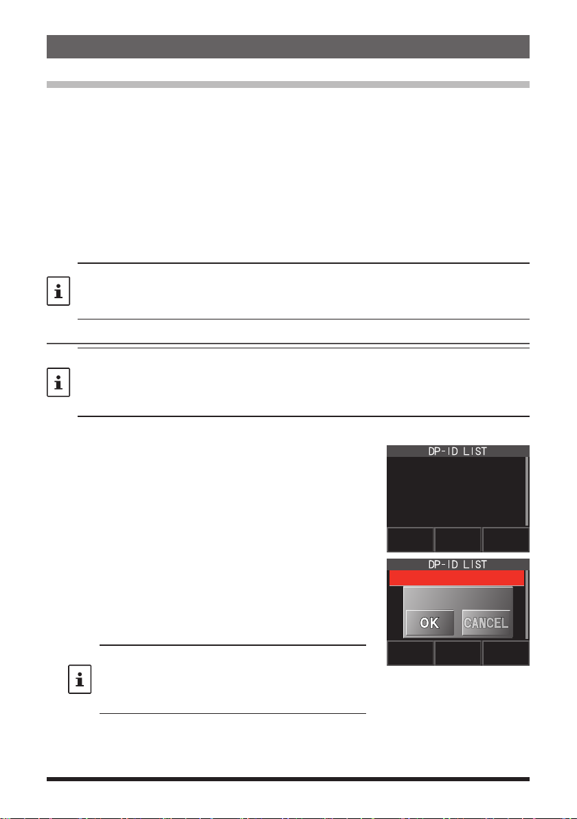
1. Press and hold the [DISP] key touch [GM] touch [1 DP-ID LIST
• The DP-ID list is displayed.
• If a number of DP-IDs are registered, rotate the
DIAL knob to display the desired DP-ID.
2. A transmission in the digital C4FM mode from the other
transceiver will register the DP-ID.
When a signal from the other station is received, the
W6DXC
REGISTRATION?
callsign and “REGISTRATION?” are displayed on the
LCD.
• When a signal from another registered transceiver is
received, nothing is display on the LCD.
• When registering a transceiver already registered
with a different call sign, the call sign registered in the
DP-ID list is changed to the new registered call sign.
4
].
Page 5
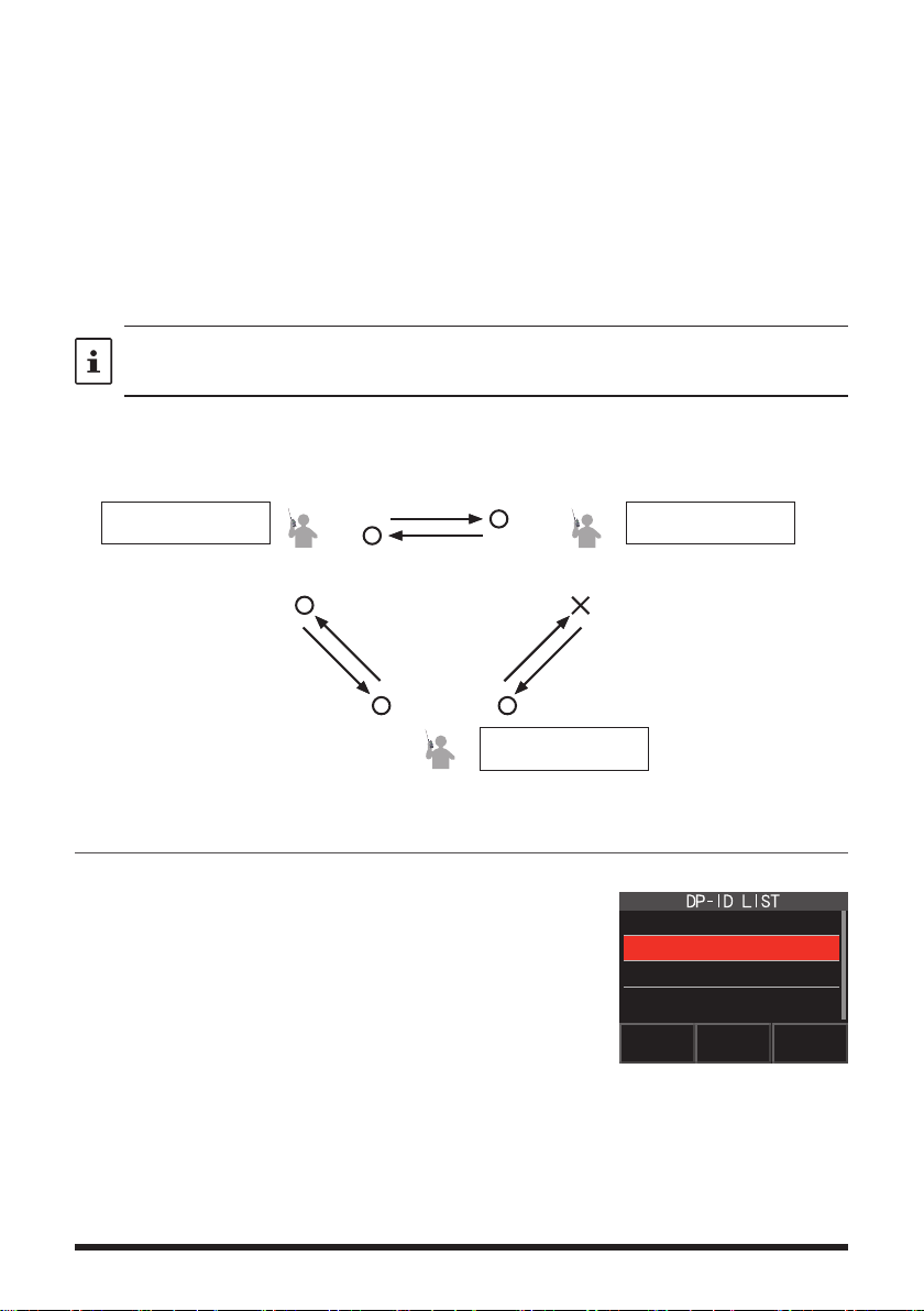
3. Touch [OK] to save the setting.
DG-ID: TX01 RX01
A station and C station do not register
the DP-ID of each other
on both transceivers, but each
transceivers may communicate
because the same DG-ID is set to
both transceivers.
The transceivers may communicate
B Station may not receive the C
station's signal because B station does
C station may receive the B station's
signal because C station register the B
• When registering in the DP-ID list is finished, “COMPLITED” is displayed for three
seconds, then the display returns to the DP-ID list screen.
• If not registering the DP-ID, press the [CANCEL].
• If registering several DP-IDs, repeat step 2 and 3.
• A maximum of 24 stations may be registered.
4. Press the PTT switch to save the setting and return to normal operation.
• Similarly, register all of the communicating transceivers’ DP-IDs to the DP-ID lists
of the other stations.
• The DP-ID setting is complete.
For communicating using the DP-ID function, register the DP-ID of each other’s transceiver
on both transceivers. By registering the DP-ID, users may communicate even if the Digital
group ID (DG-ID) is a different setting
even if the Digital Group ID (DG-ID) is
a different setting because A Station
and B station register the DP-ID of
each other's transceiver on both
transceivers.
DP-ID list
B station's DP-ID “bbbbb”
A B
DP-ID: aaaaa
DG-ID: TX01 RX01
DP-ID: bbbbb
DG-ID: TX02 RX02
DP-ID list
A station's DP-ID “aaaaa”
Deleting the registered DP-ID
1. Press and hold the [DISP] key touch [GM] touch [1 DP-ID LIST
The DP-ID list is displayed.
's transceiver
DP-ID: ccccc
C
B station's DP-ID “bbbbb”
5
not register the C station's DP-ID.
station's DP-ID.
DP-ID list
].
1 JA1ZRL
2 W6DXC
3 JQ1YBF
Page 6
2. Rotate the DIAL knob to select the call sign of the
other transceiver, then touch [DEL].
Confirmation screen “DELETE?” is displayed.
W6DXC
DELETE?
3. Touch [OK] to delete.
• When finished registering in the DP-ID list, “COMPLETED” is displayed for three
seconds.
• If not registering another DP-ID, touch [CANCEL].
• If deleting several DP-IDs, repeat step 2 and 3.
4. Press the PTT switch to save the setting and return to normal operation.
Communicating with specified other station in the Analog FM mode
Selecting the Squelch Type in the Analog FM Mode
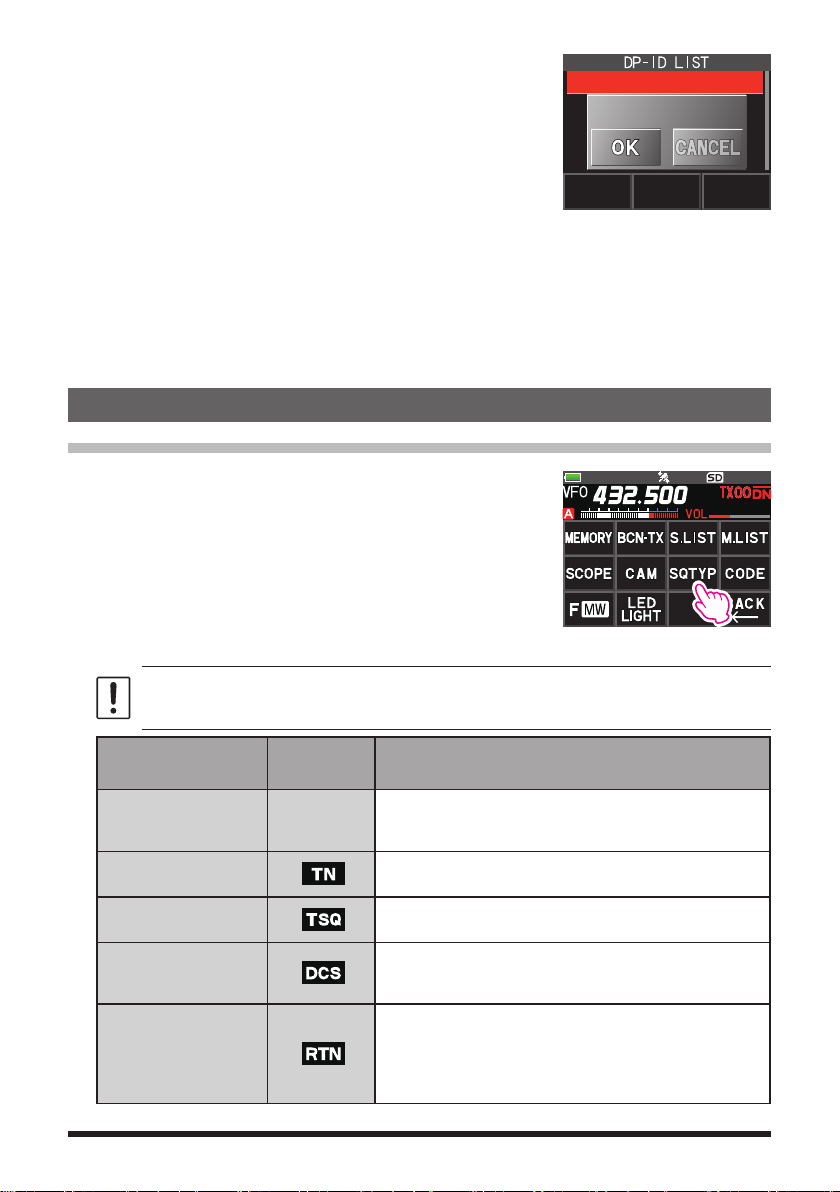
1. Touch [F MW] [GM].
If [SQTYP] is not displayed, touch [FWD →] to display
[SQTYP] and then touch it.
2. Turn the DIAL knob and select the type of squelch, refer to the table below.
Tone squelch (CTCSS), DCS and the New PAGER (EPCS) functions do not operate in
the C4FM digital mode. Touch [MODE] to change to the Analog FM mode, or turn the
AMS function ON.
Squelch type
OFF
TONE
TONE SQL
DCS
REV TONE
Icon
indication
-
Deactivates the tone squelch function and DCS function
OFF, then returns to the normal squelch operation in the
Analog FM mode.
Analog FM Transmissions contain the CTCSS tone.
Receives as a normal squelch operation.
Activates the CTCSS tone squelch function on Analog
FM receive.
Activates the Digital Code Squelch (DCS) function.
The DCS code may be selected from 104 codes (from
023 to 754).
Activates the reverse tone function.
Used to monitor communications based on the squelch
control system. When a signal contains the designated
tone, the squelch is not opened, and when the tone signal
disappears, the squelch opens, and communication starts.
Description
6
Page 7

Squelch type
PR FREQ
PAGER
D CD*
TONE-DCS*
D CD-TONE SQL*
Icon
indication
Activates the no-communication squelch function for
radios.
The no-communication signal tone frequencies may
be specified within the range from 300 Hz to 3000 Hz
in steps of 100 Hz.
Activates a new two-tone CTCSS pager function.
When communicating with FT3DR/DE transceivers
among friends, specify personal codes (each code is
composed of two tones) so that only specific stations
are called.
Transmits the signal containing the DCS CODE.
Receives as a normal squelch operation.
Sends a tone signal when transmitting, and receives
the only signal matches the DCS code when receiving.
Sends the DCS CODE when transmitting and receives
only signals that contain a matching tone signal when
receiving.
Description
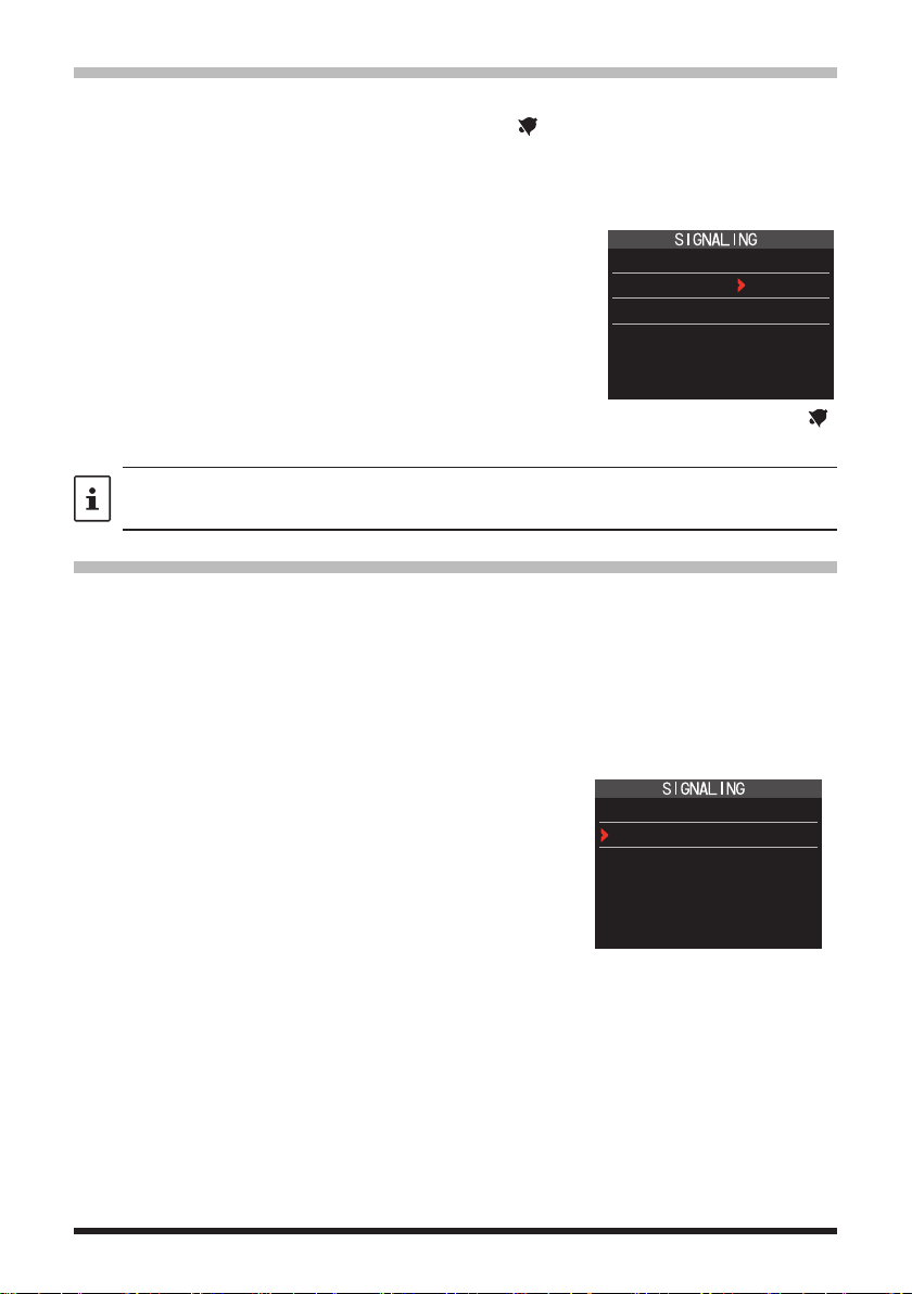
*: Press and hold the [DISP] key [SIGNALING] [10 SQL EXPANTION] set to
“ON”, “D CD”, “TONE-DCS” and “D CD-TONE SQL” setting values are activated.
3. Press the PTT switch to save the settings and return to normal operation.
• The squelch type may be set for each frequency band (BAND).
• The CTCSS and DCS squelch settings are also active during scanning. If scanning is
performed with the CTCSS and DCS squelch function activated, scanning stops only when
a signal containing the specified CTCSS tone or DCS code is received.
• Pressing the MONI/T-CALL switch allows signals that do not contain a tone or DCS code,
and signals with different tones, DCS codes, digital mode signals to all be heard.
• Press and hold the [DISP] key [SIGNALING] [DCS INVERSION] allows to receive the
DCS code of the inverted phase.
Tone squelch feature
The tone squelch opens the speaker audio only when a signal containing the specified
CTCSS tone is received. The receiver will be quiet while waiting for a call from a specific
station.
The tone squelch function does not function in digital mode. Touch [MODE] to change the
communication mode to Analog FM mode or turn the AMS function ON.
Setting CTCSS Tone frequency
The tone frequency may be selected from 50 frequencies (from 67.0 Hz to 254.1 Hz).
1. Touch [F MW] [SQTYP].
If [SQTYP] is not displayed, touch [FWD →] to display [SQTYP] and then touch it.
2. Rotate the DIAL knob to select “TONE SQL”.
3. Press the PTT switch to save the settings and return to normal operation.
7
Page 8
4. Touch [F MW] [CODE].
5. Rotate the DIAL knob to select the tone frequency.
6. Press the [BACK] key to save the setting and return to
12 TONE SQL FREQ
TONE : 100.0 Hz
normal operation.
• The tone frequency setting is common with the squelch types as follows:
TONE, TONE SQL, REV TONE, TONE-DCS, D CD-TONE SQL
• The default setting is “100.0 Hz”
Searching for the CTCSS Tone transmitted by the other Station
The tone search function does not function in digital mode. Touch [MODE] to change the
communication mode to Analog FM mode or turn the AMS function ON.
Search and display the tone squelch CTCSS tone transmitted by the other station.
1. Touch [F MW] [SQTYP].
If [SQTYP] is not displayed, touch [FWD →] to display [SQTYP] and then touch it.
2. Rotate the DIAL knob to select the “TONE SQL”.
3. Press the PTT switch to save the setting and return to normal operation.
4. Touch [F MW] [CODE].
The setting screen of the tone frequency is displayed.
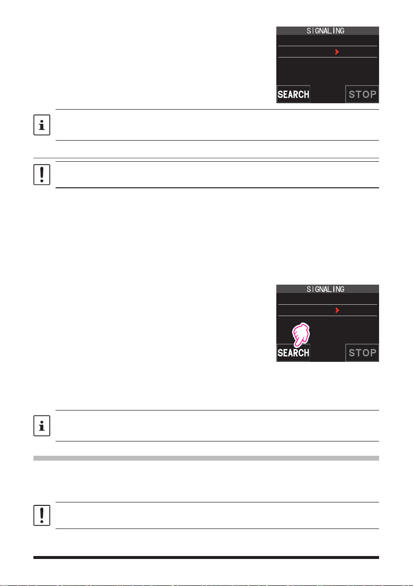
5. Touch [SEARCH].
• The transceiver begins searching for a matching
tone frequency.
12 TONE SQL FREQ
TONE : 123.0 Hz
• When a corresponding tone frequency is detected,
a beep sound is emitted, and the detected tone frequency blinks. The searching stops for 5 seconds
and the audio is heard.
6. Touch [STOP] to stop searching.
7. Press the [BACK] key to save the detected tone frequency and return to normal
operation.
To set the transceiver operation when scanning stops, press and hold the [DISP] key
[SCAN] [4 SCAN RESUME]. This setting is common with the scan setting, tone search
function and DCS search function.
Digital Code Squelch (DCS) feature
The Digital Code Squelch opens the speaker audio only when a signal containing the
specified DCS code is received.
The DCS code may be selected from 104 types (from 023 to 754).
The tone search function does not function in digital mode. Touch [MODE] to change the
communication mode to Analog FM mode or turn the AMS function ON.
8
Page 9
Setting the DCS CODE
1. Touch [F MW] [SQTYP].
If [SQTYP] is not displayed, touch [FWD →] to display [SQTYP] and then touch it.
2. Rotate the DIAL knob to select “DCS”.
3. Press the PTT switch to save the setting and return to normal operation.
4. Touch [F MW] [CODE].
5. Rotate the DIAL knob to select the DCS code.
6. Press the [BACK] key to save the detected tone
2 DCS CODE
DCS : 023
frequency and return to normal operation.
• The DCS code set by the above operation is the common setting for all transmissions with
a DCS Code (DCS, D CODE, T DCS, D TONE).
• The default DCS code is “023”.
Searching for the DCS Code Used by the Other Station
Search for the DCS code used by the other station.
1. Touch [F MW] [SQTYP].
If [SQTYP] is not displayed, touch [FWD →] to display [SQTYP] and then touch it.
2. Rotate the DIAL knob to select “DCS”.
3. Press the PTT switch to save the setting and return to normal operation.
4. Touch [F MW] [CODE].
The DCS code setting screen is displayed.
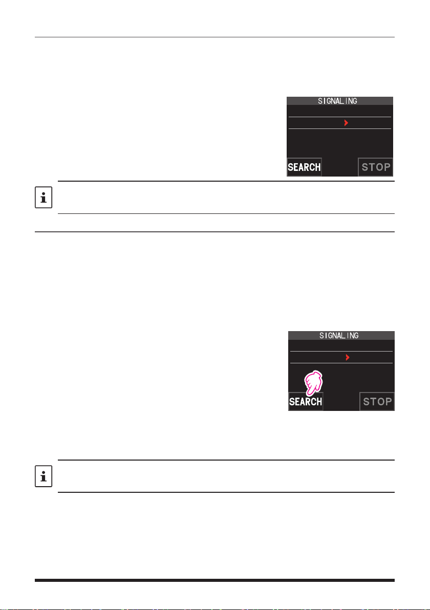
5. Touch [SEARCH].
• The transceiver starts to search for the DCS code.
• When a corresponding DCS code is detected, a
2 DCS CODE
DCS : 023
beep sound is emitted. The detected DCS code
blinks. The searching stops for 5 seconds and the
audio is heard.
6. Touch [STOP] to stop searching.
7. Press the [BACK] key to save the detected DCS code and return to normal
operation.
To set the transceiver operation when scanning stops, press and hold the [DISP] key
[SCAN] [4 SCAN RESUME]. This setting is common for all scan settings, the tone search
function and DCS search function.
9
Page 10
New Two-Tone CTCSS Pager Function
When using FT3DR/DE transceivers with a group of friends, setting the Two-Tone
CTCSS personal codes allows calling just the specific stations. Even when the person
who is called is not near the transceiver, the information on the LCD indicates that a call
was received.
The new two-tone CTCSS pager feature does not operate in digital mode. Touch [MODE] to
change the communication mode to Analog FM mode or turn the AMS function ON.
Using the Pager Function
1. Touch [F MW] [SQTYP].
If [SQTYP] is not displayed, touch [FWD →] to display [SQTYP] and then touch it.
2. Rotate the DIAL knob to select the “PAGER”.
3. Press the PTT switch to save the setting and return to normal operation.
Setting the Code for Your Station
Set the “pager code” to be called by other stations.
1. Activate the pager function by referring to “Using the pager function” above.
2. Touch [F MW] [CODE].
If [CODE] is not displayed, touch [FWD →] to display [CODE] and then touch it.
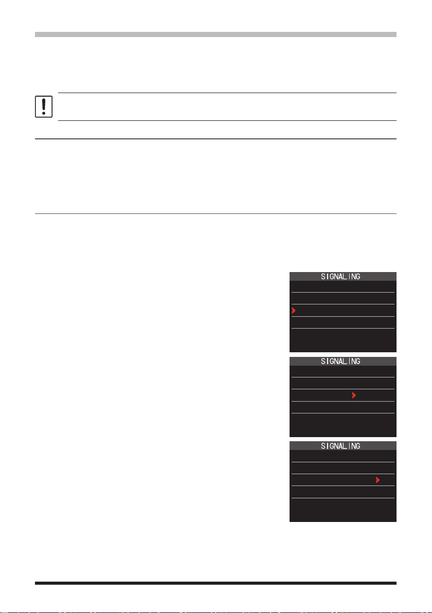
3. Rotate the DIAL knob to select “CODE-RX”.
6 PAGER
ANS-BACK: OFF
CODE-RX : 05 47
CODE-TX : 05 47
4. Press the [DISP] key to move the “u” icon to the first
element of the code.
Rotate the DIAL knob to select the first element of the
code from 1 to 50.
5. Press the [DISP] key to move the “u” icon to the
second element of the code.
Rotate the DIAL knob to select the second element of
the code from 1 to 50.
The same code cannot be use for both elements.
6. Press the PTT switch to save the setting and return to
normal operation.
10
6 PAGER
ANS-BACK: OFF
CODE-RX : 05 47
CODE-TX : 05 47
6 PAGER
ANS-BACK: OFF
CODE-RX : 05 47
CODE-TX : 05 47
Page 11
• The reverse combination works as the same code, that is “05 47” is the same as “47 05”.
• If the same code is specified for all individuals, all the individuals can be called at the same
time.
• The default code is “05 47”.
• When receiving the signals, the intermittent sound of the tone signal may be heard slightly.
Calling a Specific Station
The “pager code” may be set to call specific stations.
1. Activate the pager function by referring to “Using the Pager Function” (page 10).
2. Touch [F MW] [CODE].
If [CODE] is not displayed, touch [FWD →] to display [CODE] and then touch it.
3. Rotate the DIAL knob to select “CODE-TX”.
4. Press the [DISP] key to move the “u” icon to the first element of the code.
Rotate the DIAL knob to select the first element of the code from 1 to 50.
5. Press the [DISP] key to move the “u” icon to the second element of the code.
Rotate the DIAL knob to select the second element of the code from 1 to 50.
The same code cannot be use for both elements.
6. Press the PTT switch to save the setting and return to normal operation.
7. Press the PTT switch to transmit a call to the specific station.
Receiving “pager code” calls from a Remote Station (Standby Operation)
When the Pager function is activated, and a call is received with a corresponding Code,
the audio is heard. When the PTT switch is pressed, the “
” icon blinks and the other
station's audio is heard regardless of whether the code matches or not. About 10 seconds after the signal disappears, the “
” icon will light, and the sound of the unmatched signal will not be heard.
Furthermore, when the Bell function (see below) is activated, the bell rings and the “
icon blinks when receiving calls from the other station.
Using the Pager Answer Back
when called by another station with a corresponding pager code, the transceiver is automatically placed in the transmit mode (for about 2.5 seconds) to notify the other station
that you are ready to communicate.
1. Activate the pager function by referring to “Using the Pager Function” (page 10).
2. Touch [F MW] [CODE].
If [CODE] is not displayed, touch [FWD →] to display [CODE] and then touch it.
3. Press the [DISP] key, and then rotate the DIAL knob
to select “ON”.
6 PAGER
ANS-BACK: ON
CODE-RX : 05 47
CODE-TX : 05 47
”
4. Press the PTT switch to transmit a call to the specific station.
11
Page 12
Notification of a Call from a Remote Station by the Bell Function
The Bell may be set to sound an Alert when a call from another station containing a corresponding tone, DCS or pager code is received. “
vide a later notice of the call from the other station.
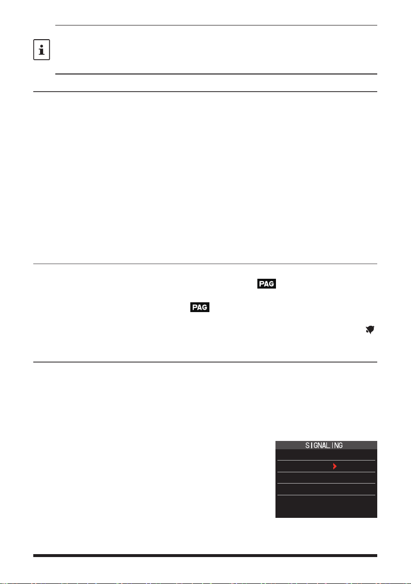
1. Press and hold the [DISP] key touch [SIGNALING] [1 BELL].
2. Press the [DISP] key.
3. Rotate the DIAL knob to select “BELL”.
4. Press the [BACK] key, and then rotate the DIAL knob
to select “RINGER”, and then press the [DISP] key.
5. Rotate the DIAL knob to select the desired number of
times (1-20 times or continuous) the Bell rings.
•••1time↔2times↔•••↔20times↔CONTI•••
6. Press the PTT switch to save the setting and return to normal operation, and the “ ”
icon appears on the display.
If the setting is “CONTI” (continuous), the bell keeps sounding until an operation is made.
” icon on the display blinks to pro-
1 BELL
SELECT : BELL
RINGER : 1time
User Programmed Reverse CTCSS Decoder
The tone signal frequency can be set at 100 Hz intervals between 300 Hz and 3000 Hz
to mute the audio when receiving a signal containing a CTCSS tone matching the programmed tone.
1. Touch [F MW] [SQTYP].
2. Rotate the DIAL knob to select “PR FREQ”.
3. Press the PTT switch to save the setting and return to
normal operation.
4. Touch [F MW] [CODE].
The setting screen containing the CTCSS tone frequencies is displayed.
5. Rotate the DIAL knob to select the desired CTCSS
tone frequency.
300Hz to 3000Hz (100Hz steps)
6. Press the PTT switch to save the setting and return to
normal operation.
7 PR FREQUENCY
1600Hz
12
Page 13
CAM (Club Channel Activity Monitor) function
Return to the frequency before memory channel selectionCAM Group selection
Up to 10 groups with 5 channels each, of frequently used memory channels* may be
registered, and then while receiving the current frequency, the status (signal strength) of
the selected group of memory channels may be displayed. It is easy to identify on which
channel the communication was made.
When a memory channel on the graph is touched, it will become the center operating
frequency, so communication with friends may begin immediately.
* Only channels in the frequency range of 108 MHz to 579.995 MHz may be stored.
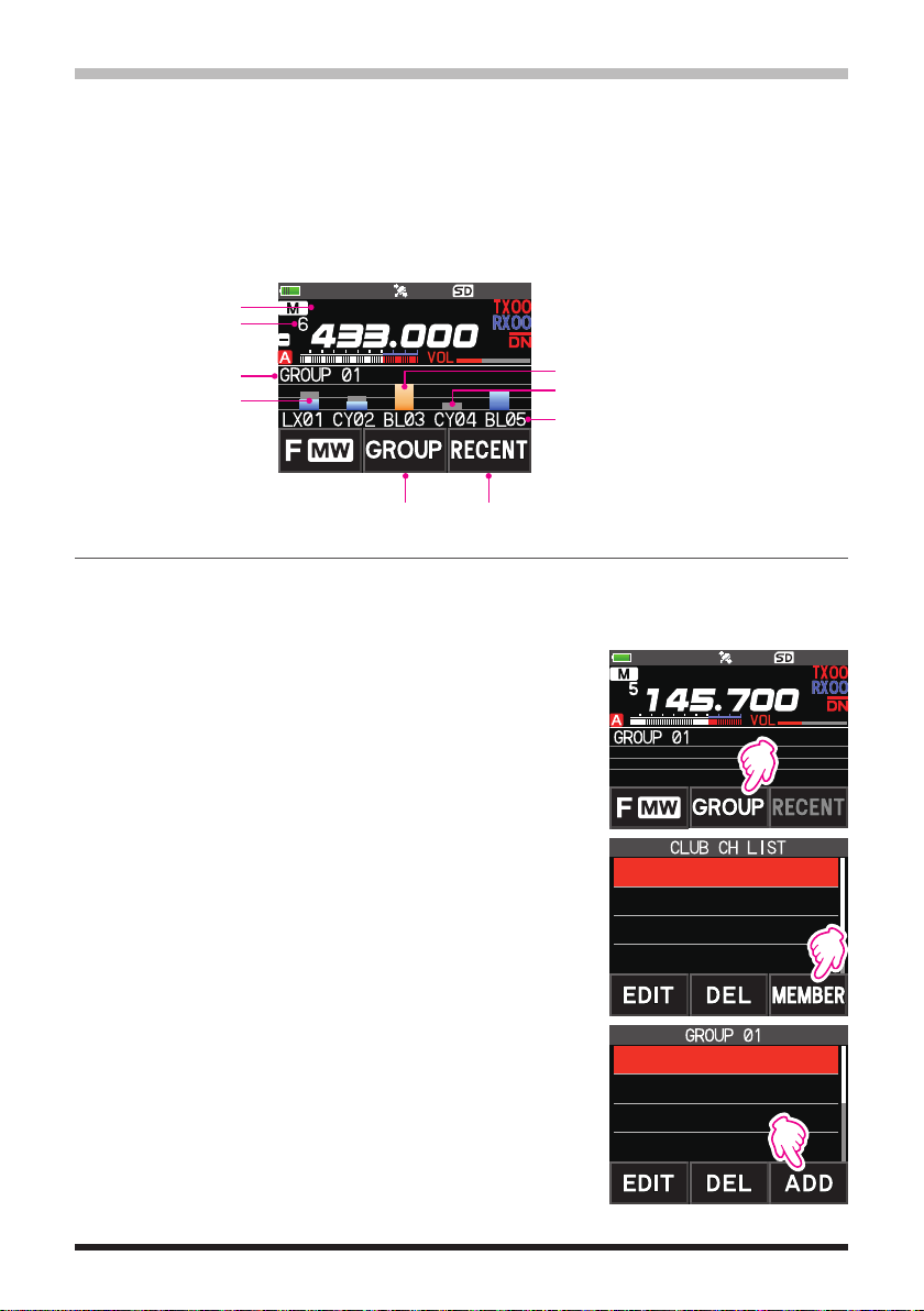
Memory channel tag
Memory channel number
currently selected
CAM Group tag display
Touch the bar graph, it will
be the transmit/receive
frequency.
YAESU
Currently selected memory channel
(displayed in yellow)
Display in gray even if the received signal is lost
CAM memory channel tag display
Register memory channel to CAM group
1. Touch [F MW] [CAM].
• If [CAM] is not displayed, touch [FWD →] to display [CAM] and then touch it.
• The CAM screen is displayed.
2. Touch [GROUP], and then turn the DIAL knob to select
the group (CAM1 to 10) to be registered.
YAESU
3. Touch [MEMBER].
A list of memory channels registered to the CAM group
is displayed.
1 GROUP 01
2 GROUP 02
3 GROUP 03
4 GROUP 04
4. Touch [ADD].
G1-1 1 145.30.00
G1-2 5 439.700.00
G1-3 6 432.500.00
G1-4 ----------------
13
Page 14
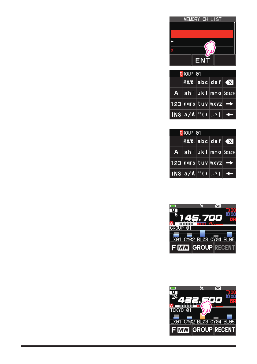
5. Rotate the DIAL knob to select the memory channel to
register, and touch [ENT].
• Repeat step 5 to register multiple memory channels.
• Up to 5 channels can be registered in one group.
6. Press the [BACK] key to return to the CAM screen.
zChanging the name (tag) of CAM group
Change the name of CAM group from the default setting.
1. In step 2 of “Register memory channel to CAM group”,
turn the DIAL knob to select the group to change the
tag.
2. Touch [EDIT] and enter up to 16 characters for the CAM
group tag.
zChange the name (tag) of CAM memory
Change the name of Memory channels registered in the
CAM group from the default setting.
1. In step 3 of “Register memory channel to CAM group”,
turn the DIAL knob to select the memory channel to
change the tag.
2. Touch [EDIT] and enter up to 4 characters for the CAM
memory channel tag.
1 145.030.00
2 439.700.00
3 145.620.00
4 432.500.00
Using the CAM function
1. Touch [F MW] [CAM].
• If [CAM] is not displayed, touch [FWD →] to display
[CAM] and then touch it.
• The CAM screen is displayed, and the signal strength
of the channel that received the signal is displayed as
a bar graph.
• On the channel that received the signal, the bar graph
will continue to display in gray even if there is no signal, so later you can check the channel on which the
communication was performed, and the maximum
signal strength received later.
zTouch the bar graph to switch the frequency
1. Touch the bar graph on the screen.
• The touched bar graph is displayed in yellow and
switched to the memory channel frequency and received.
• Press the PTT switch to transmit as it is, so you can
start communicating with the other station immediately.
• Touch [RECENT] to return to the original frequency.
14
YAESU
YAESU
Page 15

zChange the displayed CAM group
1. Touch [GROUP].
2. Rotate the DIAL knob to select the CAM group (CAM1
to 5) to be displayed.
3. Press the [BACK] key to return to the CAM screen.
zDisable the CAM function
1. Press the [BACK] key.
Delete CAM group
1. Touch [GROUP] on the CAM screen, and then rotate the
DIAL knob to select the CAM group (GROUP 01 to 10)
to be deleted.
2. Touch [DEL].
Confirmation screen “DELETE?” is displayed.
3. Touch [OK] twice.
• The CAM group is deleted and the channel list is dis-
played again.
• To cancel the deleting, touch [CANCEL].
1 GROUP 01
2 GROUP 02
3 GROUP 03
4 GROUP 04
YAESU
1 GROUP 01
2 GROUP 02
3 GROUP 03
4 GROUP 04
Delete a registered memory channel from CAM group
1. Touch [GROUP] on the CAM screen, and then touch
the CAM group (GROUP 01 to 10) in which the memory
channel to be deleted is registered.
2. Touch [MEMBER].
The memory channels registered in the group are displayed in a list.
15
YAESU
1 GROUP 01
2 GROUP 02
3 GROUP 03
4 GROUP 04
Page 16

3. Rotate the DIAL knob to select
4. Touch [DEL].
Confirmation screen “DELETE?” is displayed.
5. Touch [OK] twice.
• The memory channel is deleted from the CAM group
LX01 001 445.012.50
CY02 005 445.212.50
BL03 006 445.312.50
-------------------
and the list display returns.
• To cancel the deleting, touch [CANCEL].
Memory Channel List
Since memory channels are displayed in a list, you can easily recall the memory by
checking the frequency and memory tag display.
1. Touch [F MW] [MEMORY].
• If [MEMORY] is not displayed, touch [FWD →] to dis-
play [MEMORY] and then touch it.
• You can switch between memory tag display and fre-
quency display by press and hold the [V/M] key.
• The “
” icon is displayed at the left of memory chan-
nels set as skip memory, and the “
” icon is displayed
1 145.030.00
2 439.700.00
3 145.620.00
4 432.500.00
at the left of memory channels set as specified memory.
2. Rotate the DIAL knob to select the desired memory channel.
3. Touch [ENT] to recall the selected memory channel and enter memory mode.
The Memory Channel Only Mode
The FT3DR/DE may be set to operated only in the registered memory channels.
1. While pressing the [V/M] key, press and hold the POWER switch to turn the transceiver ON.
• The memory channel only mode is ON, the previously selected memory channel is
recalled.
• Rotate the DIAL knob to select the memory channels.
• Touch the frequency display to display the numeric keypad, enter a 3-digit memory
channel number, and then touch [ENT] to recall the memory channel.
• In the memory only mode, only the following functions will operate:
•Changing the communication mode (touch [MODE])
•The transmission mode setting of the AMS function (touch [AUTO], [TX FM] or [TX DN])
•Group monitor (GM) function (press the [GM] key)
•WIRES-X function (press the [X] key)
•Audio level adjustment
•SQL level adjustment (press the [SQL] key)
•Key lock function (press the POWER switch)
• Pressing the [V/M] key, will sound the beep, “M-ONLY” will be displayed, and the function
will not operate.
zCanceling Memory Only Mode
1. Turn the transceiver OFF; and then while pressing the [V/M] key, press and hold the
POWER switch to turn the transceiver ON.
16
Page 17

Using Memory Banks
The transceiver allows using up to 24 memory banks to be recalled with the sorted
memory channels. One memory channel may also be registered in two or more memory
banks according to the intended use.
Example of registering memory channels to the memory banks:
Memory channels Memory banks
1 145.000 MHz
2 145.500 MHz
3 120.400 MHz
4 5 439.700 MHz
6 432.800 MHz
7 108.700 MHz
8 9 10 -
~
900 -
Registering to Memory Banks
1. Press the [V/M] key to enter the memory mode.
2. Rotate the DIAL knob to recall the memory channel to
register in the memory bank.
BANK1 (1 - 100) 144 MHz Amateur Band Channels
BANK2 (1 - 100) 430 MHz Amateur Band Channels
BANK3 (1 - 100)
BANK4 (1 - 100) All Amateur Band Channels
BANK5 (1 - 100)
BANK6 (1 - 100) Air Band Channels
BANK7 (1 - 100)
BANK8 (1 - 100)
BANK9 (1 - 100)
BANK10 (1 - 100)
~
BANK24 (1 - 100)
3. Touch and hold [F MW].
Memory channel will blink.
BANK 1
4. Rotate the DIAL to select the memory bank (BANK1 to
BANK24) to register the memory channel.
The memory bank channels are displayed between the memory channel 1 (1CH),
and PMS memory channel U50.
5. Touch [M.WRITE].
The memory channel is registered in the selected memory bank and the transceiver
operation returns to the memory mode.
17
Page 18

Open the Memory Bank display
1. Press the [V/M] key to enter the memory mode.
2. Touch [F MW] [BANK].
Memory Bank Number
Memory Channel Number
If [BANK] is not displayed, touch [BACK ←] to display [BANK] and then touch it.
B1 to B24: The memory bank display
: The memory channel display
If no memory channel is registered, setting the following operation sounds the beep and “NO
BANK” will be displayed.
zDisable the memory bank display
1. Touch [F MW] [MR].
If [MR] is not displayed, touch [BACK ←] to display [MR] and then touch it.
Open Memory Bank Channels
1. While the memory bank is displayed, press the [BAND] key.
2. Rotate the DIAL knob to select the memory bank (BANK1 to BANK24) to be
recalled.
If no memory channel is registered, the memory bank may not be selected.
3. Press the [BAND] key or PTT switch.
The selected memory bank is activated.
Canceling a Memory Channel Registered in Memory a Bank
1. Recall the memory bank to cancel registering.
2. Touch and hold [F MW].
3. Rotate the DIAL knob to select the memory channel to cancel registering to the
memory channel.
4. Touch [
], and then touch [M.DEL].
18
Page 19

Assigning a Name to a Memory Bank
A name can be assigned to a memory bank using up to 16 characters.
The following types of characters can be entered:
• Alphabetic characters (1 byte and 2 byte letters, uppercase and lowercase characters)
• Numbers (1 byte and 2 byte numbers)
• Symbols
1. Press and hold the [DISP] key touch [MEMORY]
[2 BANK NAME
2. Touch the bank where you want to edit the tag.
• The character input screen is displayed.
• Use the numeric keys or DIAL knob, to input the
name characters.
• Touch
• For additional details on inputting a memory tag,
3. When input is complete, press the PTT switch to save the
characters and return to normal operation.
【
refer to the Operating Manual “Text input screen” on
page 89.
The default memory bank names are set from “BANK 1” to
“BANK24. Each name may be changed.
].
: to move the cursor to the right
】
19
Page 20

Split Memory
Two different frequencies, one for receive and another for transmit, may be registered to
a memory channel.
1. Register the receive frequency to a memory channel
first.
• For additional details on registering to a memory
channel, refer to the Operating Manual “Registering to
Memory Channels”.
2. Set the transceiver to the desired transmit frequency.
3. Touch and hold [F MW].
4. Rotate the DIAL knob to select the channel number that
the receive frequency was registered to on step1.
5. While pressing and holding the PTT switch, press the
[M.WRITE] key.
• The beep sounds and the split memory is saved.
• While recalling the split memory, “
” is displayed on
the LCD.
Registering the receive
frequency.
Registering the transmit
frequency.
Recalling the split memory
While operating the split memory, touch [F MW] [REV], to reverse the transmit and receive
frequencies temporarily. When reversing the frequencies,“
” will blink.
20
Page 21

Setting Skip Memory Channel and Specified Memory Channel
For efficient memory channel scanning, two types of memory channels may be designated, “skip memory channels” and “specified memory channels”. Set “Skip Memory
Channels” will be skipped during the memory scanning; and only “Specified Memory
Channels” will be scanned during specified memory channel scanning.
1. Recall the memory channel to skip or specify.
2. Press and hold the [DISP] key touch [MEMORY]
[5 MEMORY SKIP].
3. Rotate the DIAL knob to change as follows:
••• OFF SKIP
• SKIP: Skip Memory Channel
The “
number lights up, and then the channel is
skipped during scanning of memory channels.
• SELECT: Specified Memory Channel
The “
number lights up, and then only designated
memory channels are scanned during memory scanning.
• OFF: Normal Memory Channel
The “
nel number turns OFF.
zScanning Only the Specified Memory Channels
1. Recall the memory channel registered as a specified memory channel.
2. Touch [F MW] [SCAN].
• If [SCAN] is not displayed, touch [BACK ←] to display [SCAN] and then touch it.
• Only the memory channels registered as the specified memory channels are
scanned.
SELECT •••
” at the right of the memory channel
” at the right of the memory channel
” or “ ” at the right of the memory chan-
Skip Memory
Specified Memory
Unless two or more specified memory channels are registered, the specified memory
channel scanning does not function.
Skipping Unwanted Scan Frequencies (Skip Search Memory)
During the VFO scan, an unwanted frequency may be skipped by registering it to the “skip
search memory channels” in advance.
zSet the temporary scan stop to the skip search memory
1. Press and hold the [F MW] key to temporarily stop the VFO scan.
2. Rotate the DIAL knob to select a skip search memory channel from 901-999.
Only skip search memory channels 901-999 may be selected.
3. Touch [M.WRITE].
The beep sounds, and the search skip channel is saved to memory, then the scan
resumes.
zSpecifying Unwanted VFO Scan Frequencies
21
Page 22

1. In the VFO mode, set the frequency that you do not want to receive.
2. Register the skip search memory (901-999) with the same steps as “Registering to
Memory Channels” (see the Operating Manual).
The skip search memory may be deleted with the same steps as “Clearing Memories” (see
the Operating Manual). The deleted frequency is scanned again.
Programmable Memory Channel Scan (PMS)
Registering to the Programmable Memory Channels
50 sets of PMS memory channels (L1/U1 to L50/U50) are available.
• Register the lower and upper frequencies of the frequency range in a pair of Program-
mable Memory Channels.
L
Lower limit memory channel
££
:
U
Upper limit memory channel
££
:
• For more details on registering frequencies to the memory channel, see “Registering
to Memory channels” (see the Operating Manual).
• Make sure to use the corresponding numbers for the lower and upper limit memory
channels.
• Set the PMS memory channel for performing the Programmable Memory scanning (PMS)
as follows:
• The scan width of the upper and lower limit frequencies must be 100 kHz or more.
• The lower and upper limit memory channels must be within the same frequency band.
• The lower and upper limit memory channels must not be registered in reverse.
• The PMS memory channel must not be registered as a skip memory channel.
Performing Programmable Memory Channel Scan
The programmable memory channel scan allows scanning a specified frequency range
within the same frequency band.
1. Recall the PMS memory channel to which the lower limit (L££) or upper limit (U££)
of the frequency band is registered.
2. Touch [F MW] [SCAN].
• If [SCAN] is not displayed, touch [BACK ←] to display [SCAN] and then touch it.
• Programmable memory channel scanning starts.
• During scanning, “PMSP££” appears on the upper left side of the display.
• If the DIAL knob is rotated while scanning is in progress, the scanning will contin-
ue up or down in frequency according to the direction of the DIAL Knob rotation.
If the scanner halts on an incoming signal, the back light will turn ON and the decimal point between the “MHz” and “kHz” digits of the frequency display will blink.
Scanning will resume in about five seconds.
3. Touch [STOP] or press the PTT switch to cancel the scanning.
In this state (displayed as “PMSP££” at the upper left of the display), the frequency
can be changed by turning the DIAL knob only in the upper/lower limit frequency
range stored by PMS memory.
zDisable the PMS function
1. Press the [V/M] key.
Return to the normal memory mode.
22
Page 23

Memory Bank Scanning
Scan only the memory channels stored in the recalled memory bank.
1. Recall the memory bank you want to scan by referring to “Open the Memory Bank
display” (page 18) and “Open Memory Bank Channels” (page 18).
2. Touch [F MW] [SCAN].
If [SCAN] is not displayed, touch [BACK ←] to display [SCAN] and then touch it.
Memory bank scan starts.
Memory Bank Link Scanning
During regular memory bank scanning, only the memory channels assigned to the recalled memory bank are scanned. During memory bank link scanning, you can scan
memory channels registered in two or more banks you specified in advance.
Setting Bank Link
1. Press and hold the [DISP] key touch [MEMORY] [1 BANK LINK].
2. Rotate the DIAL to select the memory bank for which you want to perform bank link
scanning.
3. Press the [DISP] key, a check mark will appear and it will be set to Bank Link.
4. Repeat steps 3 and 4 to select other memory banks.
5. Press the PTT switch to save the setting and return to normal operation.
Performing Bank Link Scan
1. Recall the memory bank set as bank link by referring to “Open the Memory Bank display” (page 18) and “Open Memory Bank Channels” (page 18).
The memory bank number is changed from [B] to [b] and the bank link scanning is
activated.
2. Touch [F MW] [SCAN].
If [SCAN] is not displayed, touch [BACK ←] to display [SCAN] and then touch it.
Bank Link Scanning is performed toward the higher memory channel numbers.
Press and hold the [DISP] key touch [SCAN] [5 SCAN WIDTH] [BANK LINK] is set
to “OFF”, to temporarily disable banklink and perform normal memory-bank scanning while
banklink is set.
23
Page 24

Dual Receive (D.RCV) Function
The transceiver is equipped with the following 3 types of Dual Receive Functions:
• VFO Dual Receive
• Memory Channel Dual Receive
• Home Channel Dual Receive
The transceiver checks for signals on the frequency registered to the selected memory
channel (Priority Memory Channel) once approximately every 5 seconds. When receiving a signal on the frequency registered to a priority memory channel, the Dual Receive
function automatically pauses, and allows reception of the signals.
Example: Checking the priority memory channel “100” (145.000 MHz), while receiving
“432.500 MHz”.
The transceiver monitors signals
VFO
on the frequency registered to the
Priority Memory Channel, once
approximately every 5 seconds.
Priority
Memory Channel
The transceiver returns to
the previous frequency
quickly and continues to
receive mode when there
is no signal.
When the transceiver receives
a signal on the frequency registered
to the priority memory channel, dual
reception stops and signal receiver
switches to priority memory channel.
Registering the priority channel
1. Register the preferred receive frequency and communication mode to the priority
memory channel (see the operating manual).
2. Press the [V/M] key to recall the memory channel.
3. Touch and hold [F MW], and then rotate the DIAL knob
to select the memory channel registered in step 1.
4. Touch [PRI.CH].
• The priority memory channel setting is saved and op-
eration returns to the prior recalled memory channel.
• When recalling the priority memory channel, the “
”
icon appears on the upper right side of the memory
channel number.
24
Page 25

Activating the Dual Receive (D.RCV) feature
1. Set the frequency and communication mode to monitor continually.
The monitor frequency may be set on the VFO mode, the memory channel mode or
the HOME channel mode.
VFO Dual Receive
VFO Priority Memory Channel
Memory Channel Dual Receive Memory Channel Priority Memory Channel
HOME Channel Dual Receive HOME channel
Priority Memory Channel
2. Touch [F MW] [D.RCV].
• If [D.RCV] is not displayed, touch [BACK ←] to display [D.RCV] and then touch it.
• The dual receive function is activated and the following icon is displayed on the top left of the display.
VFO Dual Receive: VDR
Memory Channel Dual Receive: MDR (/DXX/dXX)*
HOME Channel Dual Receive: HDR
In the memory bank, DXX is displayed, and in the
*
memory bank where the bank link is set, dXX (XX is
a bank number) is displayed.
When a signal is received on the priority channel, the beep sounds, and the Dual
Receive function stops temporarily.
The combination of the frequency bands and modes for the Priority Memory Channel and
the receiver monitor frequency can be easily changed. Dual Receive may be operated with
the AMS function ON.
Setting the Dual Receive (D.RCV) Resume Conditions
1. Press and hold the [DISP] touch [SCAN] [4 SCAN RESUME].
2. Rotate the DIAL knob to select
“DW”.
3. Press the [DISP] key, and then rotate the DIAL knob to select the resume condition
after halting in the Dual Receive function (default setting is “HOLD”).
2.0 sec~10.0 sec The signal is received for the specified period of time, and then
the Dual Receive resumes.
The Dual Receive resume time may be set from 2 to 10 seconds at 0.5 second intervals.
BUSY
The signal is received until the signal fades out. Two seconds
after the signal fades out, the Dual Receive resumes.
HOLD The Dual Receive stops and tuning remains on the current re-
ceive frequency. (The Dual Receive does not resume.)
4. Press the PTT switch to save the new setting and return to normal operation.
Press and hold the [
press the
channel. After transmitting, the transceiver receives the priority channel and Dual Receive
resumes after 5 seconds.
PTT
DISP
switch to transmit, without waiting for activity to appear on the priority
] key touch [
SCAN
6 PRIORITY REVERT
] [
] is set to “ON”,
25
Page 26

AF-DUAL Receive Function
The AF-DUAL Receive Function allows reception of a radio broadcast during standby reception of A-band or B-band frequency (or frequency registered to a memory channel).
When standby reception is active, no audio is heard on the standby frequency, however
if a voice signal is detected, the reception of the broadcast radio will be paused, and the
receiver frequency will be heard.
Dual Receive is a similar function. When using the Dual Receive function, every time
the transceiver checks for a signal on the specified memory channel during radio reception, the radio reception is interrupted (approximately every 5 seconds). When using the
AF-DUAL Receive Function, the radio reception is interrupted only when there is a calling signal from another transceiver.
1. Set the A-band or B-band frequency for standby receive during broadcast radio reception.
2. Touch [F MW] [A.DUAL].
If [A.DUAL] is not displayed, touch [BACK ←] to
•
display [A.DUAL] and then touch it.
• The AF-DUAL function is activated, and AF DUAL
“
” icon will be displayed.
• Pressing the [BAND] key each time switches be-
tween the AM broadcast (middle wave band) and
FM broadcast.
3. Rotate the DIAL to tune to the frequency of the
broadcast station.
• The AF-DUAL receive function can also be used to monitor a radio frequency registered
to a memory channel or memory bank.
• Pressing [MONI] switch during radio reception, allows receiving the standby frequency.
• While listening to the radio using the AF-DUAL function, in standby receive mode, the
transceiver cannot simultaneously receive broadcasts on the AM frequency (middle wave
band) on either the band-A or band-B, and FM frequency.
zDisable the AF DUAL function
1. Touch [F MW] [A.DUAL].
26
Page 27

DTMF Operation
DTMF (Dual Tone Multi Frequencies) are the tone signals sent to make telephone calls,
or control repeaters and network links. Up to 10 registers of 16-digit DTMF tone codes
can be stored as telephone numbers to make calls through the public telephone network
using a phone patch or connect through the WIRES-X analog node station.
Setting the DTMF Memory
1. Press and hold the [DISP] key touch [SIGNALING] [5 DTMF MEMORY].
2. Rotate the DIAL knob to select the desired channel (1 to 10) to register the DTMF
code, then press the [DISP] key.
The DTMF memory channel input screen is displayed.
3. Use the numeric keypad or DIAL knob to input the DTMF code maximum of 16 digits.
• Using the DIAL knob:
The DTMF codes from 0 to 9 may be input.
0 to 9
•••
4. Press the PTT switch to save the setting and return to normal operation.
Transmitting the Registered DTMF Code
1. Press and hold the [DISP] key touch [SIGNALING] [4 DTMF MODE].
2. Rotate the DIAL knob to select the “MODE”.
3. Press the [DISP] key, and then turn the DIAL knob to select the setting.
AUTO
MANUAL: The DTMF code may be transmitted manually by pressing each numeric
4. Press the PTT switch to save the setting and return to normal operation.
When set to “AUTO”, the DTMF icon “
The registered DTMF code is automatically transmitted.
:
key.
Transmitting DTMF code automatically using DTMF memory
1. Set “AUTO ” by referring to “Transmitting the Registered DTMF Code” (above).
2. While pressing and holding the PTT switch, touch [DTMF].
3. Touch a numeric [0] to [9].
• The DTMF code registered in the DTMF memory channel is automatically trans-
mitted.
• Even after releasing the PTT switch, the transmission continues until the DTMF
code is completed. The transceiver is automatically returned to receive mode.
Manually Transmitting the DTMF Code
1. Set “MANUAL” by referring to “Transmitting the Registered DTMF Code” (above).
2. While pressing and holding the PTT switch, touch [DTMF].
• Touch each corresponding key to send the DTMF code
• The transmission may continue for one second after releasing the PTT switch.
A to D
* - #
•••
” will be shown on the display.
27
Page 28

Using the GPS Function
The GPS Function
GPS (Global Positioning System) is a space-based satellite navigation system that provides location and time information anywhere on the earth. It was developed by the U.S.
Department of Defense as a military system. When the GPS receiver acquires 3 or more
signals (of about 30) GPS satellites orbiting at an altitude of about 20,000 km, it can calculate and display its current position (latitude, longitude, and altitude) within a tolerance
of several meters. In addition, GPS can receive the exact time from the satellite onboard
atomic clock.
Activating the GPS Function
Activating the GPS function enables the transceiver to automatically obtain the internal
clock setting, and your location information setting from the GPS data.
The default setting is ON.
1. Press and hold the [DISP] key touch [APRS] [20 GPS POWER].
2. Rotate the DIAL knob to select “GPS ON”.
3. Press the PTT switch to save the setting and return to normal operation.
When the GPS function is active, the power consumption increases by about 18 mA. As a
result, the battery life is reduced, as compared to when the GPS function is deactivated.
Displaying Position Information of Remote Stations in Digital Mode
With V/D mode of the C4FM digital, the GPS position information is transmitted simultaneously with voice signals; therefore, the direction and position of the remote station can
be displayed in real-time even while communicating.
For details, see “Real-Time Navigation Function” (page 32)
• Even if the GPS function of your station is set to OFF, the position information of the
remote station can be displayed in V/D mode.
• When the GPS function is not active, the remote station cannot display the position
information for your station.
28
Page 29

About Positioning by GPS
“Positioning” refers to calculation of your current position from the satellite orbit information and radio propagation time. At least 3 satellites need to be acquired for successful
positioning. If positioning fails, move away from buildings as far as possible and stand
in an area with open sky.
• About errors
The measurement environment may result in positioning errors of several hundred
meters. Under favorable conditions, positioning can be performed successfully using
only three satellites. However, under the following poor conditions, the positioning accuracy can decrease or positioning can fail.
Between tall buildings
•
Narrow paths between buildings
•
Indoors or near large buildings
•
Under elevated roads or high voltage power lines
•
Between trees such as in forests or woods
•
Inside a tunnel or underground
•
Through heat reflective glass
•
Areas with strong magnetic fields
•
• When not in use for a long time
When using the GPS functions for the first time after purchase, or when it has been
unused in a while, a few minutes may be required to acquire the satellites. Also, if the
GPS function has been turned OFF for several hours, a few minutes may be required
to search for satellites.
Saving GPS Information (GPS Log Function)
The GPS position information can automatically be saved periodically onto a microSD
memory card. Using the saved data, tracks can be displayed on commercially available
map software*.
* Technical support for the map software is not provided by YAESU.
1. See “Activating the GPS Function” on page 28, and activate the GPS function.
2. Press and hold the [DISP] key touch [CONFIG] [7 GPS LOG].
3. Rotate the DIAL to select the GPS data logging interval.
OFF / 1 sec / 2 sec / 5 sec / 10 sec / 30 sec / 60 sec
4. Press the PTT switch to save the setting and return to normal operation.
The GPS log function is activated, and GPS log
• The position information is saved periodically unless “OFF” is selected in step 3 (shown
above) or the power of the transceiver is turned off.
• Reselecting the GPS data logging interval in step 3 or turning on the transceiver again,
begins saving the GPS data under a different file name.
“
icon will be displayed.
”
29
Page 30

Checking Tracks on Your PC
1. Turn off the transceiver.
2. Remove the microSD memory card from the transceiver.
3. Connect the microSD memory card to your PC using a commercially available
memory card reader.
4. Open the “FT3D” folder in the microSD memory card.
5. Open the “GPSLOG” folder.
• The data is saved as “GPSyymmddhhmmss.log”.
• The [yymmddhhmmss] part of the name consists of year (yy), month (mm), day (dd),
hour (hh), minute (mm), and second (ss).
• Tracks can be displayed on the map by importing the data to commercially available
map software.
• For information on importing, please refer to the operation manual for the map software
you use.
30
Page 31

GPS Screen Information and Operation
Activating the GPS function displays the following information on the LCD.
1. In the normal operation screen, press the [DISP] key.
If the navigation screen is displayed, touch the compass display to switch to the GPS
information screen.
①
②
③
Displays the satellite azimuth and elevation angles. Displays in North-up mode.
①
Displays the date and time.
②
Displays the current speed.
③
Displays the satellite number and reception level.
④
Displays the latitude on the upper side of the screen whereas displays the longi-
⑤
④
⑤
⑥
tude on the lower side of the screen.
The current position appears using north (N) or south (S) latitude.
Display format: X DD° MM. MMM
X: X=N: North latitude, X=S: South latitude, DD: Degree, MM:MMM Minute
Example: N 35° 37.250 (35 degrees, 37 minutes, 15 seconds north latitude)
The current position appears using east (E) or west (S) longitude.
Display format: X DDD° MM. DMMM
X: X=E: East longitude, X=W: West longitude, DDD: Degree, MM:MMM Minute
Example: E 139° 44.500 (139 degrees, 44 minutes, 30 seconds east latitude)
Displays the altitude of the current position “ALTI xxxxm”.
⑥
Example: ALTI 36m
• The GPS data units for position, speed and altitude may be changed by pressing and
holding the [DISP] key touch [APRS] [22 GPS UNIT].
• When the GPS function is used, the accurate time and date are obtained from GPS and
shown on the LCD in 24-hour format. This time data is displayed on the GPS and APRS
screens.
• The geodetic system datum (WGS-84 / Tokyo) of the built-in GPS unit may be selected by
pressing and holding the [DISP] key touch [APRS] [
However, since APRS uses the geodetic system of WGS-84, it is recommended not to
change it.
• The time zone may be set at 30-minute increments by press and hold the
touch [APRS] [
• The position information obtained from an external GPS device may be used by pressing
and holding
“INPUT” to “GPS”. In this case, the data from the internal GPS will be ignored.
• When using an external GPS device, move it away from the transceiver to reduce
interference.
28 TIME ZONE
the [DISP] key touch [APRS] [
]
(the default setting: UTC 0:00).
17 COM PORT SETTING
19 GPS SETUP] in Set mode.
[DISP] key
]
and then setting
31
Page 32

Smart Navigation Function
There are 2 methods of navigation with the Smart Navigation function.
• Real-time navigation function
• Backtrack function
Before using the smart navigation function, press and hold the [DISP] key touch [APRS]
[1 TARGET LOCATION], select “COMPASS”.
Real-Time Navigation Function
GPS position information and voice signals are simultaneously transmitted in the V/D
mode of C4FM digital. For this reason, the position and direction of the remote station
can be displayed in real time even during communication.
1. In the normal operation screen, press the [DISP] key.
If the GPS information screen is displayed, touch the compass display to switch to
the navigation display screen.
2. Touch [
3. The distance and direction to the remote station operating on the same frequency in
the V/D mode are displayed.
] to switch to the remote station location information display.
Callsign and distance to
partner station
Progress direction of
own station
JA1YOE-123
H-UP: Heading Up
N-UP: North Up
Direction of remote station
4. Press the [DISP] key to return to the normal operation display.
32
Page 33

Backtrack Function
By registering a point such as the departure point in advance, the distance and direction
to the registered point from your current position can be displayed in real time.
zRegistering Your Current Position (Departure Point)
(up to 3 Positions can Be Registered)
1. In the normal operation screen, press the [DISP] key.
If the GPS information screen is displayed, touch the compass display to switch to
the navigation display screen.
2. Touch [
You can register the other partner's callsign and current location by touching [ ] and
performing the registration operation while the remote station's location information is
displayed.
] to switch to your own station location information display.
3. Touch [MEM].
“★”, L1” and “L2” blink.
H-UP
4. Touch one of the blinking indicators to which you want
to register the position information.
• The location information is registered with the select-
H-UP
ed indicator.
5. Press the [DISP] key return to normal operation
display.
zUsing the Back Track Function
1. In the normal operation screen, press the [DISP] key.
If the GPS information screen is displayed, touch the compass display to switch to
the navigation display screen.
2. Touch the indicator ([★], [L1] or [L2]) to which you want to register the location
information for back tracking.
• The arrows in the circle indicate the direction of the
registered point (departure point). You can return to
the departure point by moving forward so that the
H-UP
arrow always points up (In case of heading up display).
3. Press the [DISP] key to return to normal operation
display.
33
Page 34

zDescription of the BACK TRACK Function Screen
Distance to the registered
Direction of registration
point
DISTANCE
position
H-UP: Heading Up
N-UP: North Up
Registration point
34
Page 35

Appendix
The folder configuration of the micro-SD card
A commercially available microSD memory card may be inserted into the FT3DR/DE to
save various data files.
The data of each function is stored in the following folders.
(root)
FT3D
BACKUP: Various setting data (BACKUP.dat)
GPSLOG: GPS Log data (yymmddhhmmss.log)
FT3D_MEMORY-CH: Memory Channel Information (MEMORY.dat)
PHOTO: image data (H+RADIO ID+xxxxx.jpg)
QSOLOG: Message data
VOICE: Voice recording data (yymmddhhmmss.wav)
The [yymmddhhmmss] part of the file name consists of year (yy), month (mm), day (dd),
hour (hh), minute (mm), and second (ss).
35
Page 36

Preset receiver channel lists
The preset receiver function presets the frequencies and memory tags (names) of 156
channels and various radio stations into the following three categories:
• Weather Broadcast Stations (10 channels)
• International VHF Marine Radio (57 channels)
• International Worldwide Broadcast (89 channels)
Recall a preset receiver
1. Press the [A/B] key to set the A-band as the operating
band.
2. Touch [F MW], and then touch [P.RCVR].
If [P.RCVR] is not displayed, touch [BACK ←] to dis-
play [P.RCVR] and then touch it.
3. Press the [BAND] key repeatedly, to select the desired
preset receiver band.
•••
WX CH INT VHF SW •••
4. Rotate the DIAL knob to select the desired channel or
frequency.
zReturn to normal mode
1. Press the [BACK] key or touch [F MW] and then touch
[P.RCVR].
VOA
36
Page 37

Weather Broadcast Stations (10 channels)
The frequencies (10 channels) used for the VHF Weather Broadcast Stations are registered.
Memory channel No. Frequency (MHz) Memory channel No. Frequency (MHz)
1 162.550 6 162.500
2 162.400 7 162.525
3 162.475 8 161.650
4 162.425 9 161.775
5 162.450 10 163.275
37
Page 38

International VHF Marine Radio (57 channels)
The frequencies used for international VHF (marine) radio are registered.
Memory channel No. Frequency (MHz) Memory channel No. Frequency (MHz)
1 156.050 160.650* 60 156.025 160.625*
2 156.100 160.700* 61 156.075 160.675*
3 156.150 160.750* 62 156.125 160.725*
4 156.200 160.800* 63 156.175 160.775*
5 156.250 160.850* 64 156.225 160.825*
6 156.300 65 156.275 160.875*
7 156.350 160.950* 66 156.325 160.925*
8 156.400 67 156.375
9 156.450 68 156.425
10 156.500 69 156.475
11 156.550 70 156.525
12 156.600 71 156.575
13 156.650 72 156.625
14 156.700 73 156.675
15 156.750 74 156.725
16 156.800 75 156.775
17 156.850 76 156.825
18 156.900 161.500* 77 156.875
19 156.950 161.550* 78 156.925 161.525*
20 157.000 161.600* 79 156.975 161.575*
21 157.050 161.650* 80 157.025 161.625*
22 157.100 161.700* 81 157.075 161.675*
23 157.150 161.750* 82 157.125 161.725*
24 157.200 161.800* 83 157.175 161.775*
25 157.250 161.850* 84 157.225 161.825*
26 157.300 161.900* 85 157.275 161.875*
27 157.350 161.950* 86 157.325 161.925*
28 157.400 162.000* 87 157.375
88 157.425
* indicates the frequency of the VHF marine base station. For example: if the preset receiver
memory channel 1 is selected, the base station frequency 160.650 MHz appears and lights
up. Touching [F MW] followed by [REV] displays the Ship Station frequency 156.050 MHz
appears and blinks. The frequency lower than the base station frequency by 4.6 MHz is the
Ship Station frequency and duplex operation may commence. To return to the base station
frequency, press [F MW] followed by [REV].
38
Page 39

International World Wide Broadcast (89 channels)
The major shortwave broadcast stations around the world are registered.
CH
Frequency
Number
(MHz)
1 6.030 VOA USA
2 6.160 VOA USA
3 9.760 VOA USA
4 11.965 VOA USA
5 9.555 CANADA Canada
6 9.660 CANADA Canada
7 11.715 CANADA Canada
8 11.955 CANADA Canada
9 6.195 BBC UK
10 9.410 BBC UK
11 12.095 BBC UK
12 15.310 BBC UK
13 6.090 FRANCE France
14 9.790 FRANCE France
15 11.670 FRANCE France
16 15.195 FRANCE France
17 6.000 DEUTSCHE WELLE Germany
18 6.075 DEUTSCHE WELLE Germany
19 9.650 DEUTSCHE WELLE Germany
20 9.735 DEUTSCHE WELLE Germany
21 5.990 ITA LY Italy
22 9.575 ITA LY Italy
23 9.675 ITA LY Italy
24 17.780 ITA LY Italy
25 7.170 TURKEY Turkey
26 7.270 TURKEY Turkey
27 9.560 TURKEY Turkey
28 11.690 TURKEY Turkey
29 9.660 VATICAN Vatican
30 11.625 VATICAN Vatican
31 11.830 VATICAN Vatican
32 15.235 VATICAN Vatican
33 5.955 NEDERLAND Netherlands
34 6.020 NEDERLAND Netherlands
35 9.895 NEDERLAND Netherlands
36 11.655 NEDERLAND Netherlands
37 5.985 CZECH LIBERTY Czech Republic
38 6.105 CZECH LIBERTY Czech Republic
39 9.455 CZECH PRAGUE Czech Republic
40 11.860 CZECH LIBERTY Czech Republic
41 9.780 PORTUGAL Portugal
42 11.630 PORTUGAL Portugal
43 15.550 PORTUGAL Portugal
44 21.655 PORTUGAL Portugal
45 9.650 SPAIN Spain
Name
Broadcast Station
Name
CH
Frequency
Number
(MHz)
46 11.880 SPAIN Spain
47 11.910 SPAIN Spain
48 15.290 SPAIN Spain
49 6.055 NIKKEI Japan (Nikkei)
50 7.315 NORWAY Norway
51 9.590 NORWAY Norway
52 9.925 NORWAY Norway
53 9.985 NORWAY Norway
54 6.065 SWEDEN Sweden
55 9.490 SWEDEN Sweden
56 15.240 SWEDEN Sweden
57 17.505 SWEDEN Sweden
58 6.120 FINLAND Finland
59 9.560 FINLAND Finland
60 11.755 FINLAND Finland
61 15.400 FINLAND Finland
62 5.920 RUSSIA Russia
63 5.940 RUSSIA Russia
64 7.200 RUSSIA Russia
65 12.030 RUSSIA Russia
66 7.465 ISRAEL Israel
67 11.585 ISRAEL Israel
68 15.615 ISRAEL Israel
69 17.535 ISRAEL Israel
70 6.045 INDIA India
71 9.595 INDIA India
72 11.620 INDIA India
73 15.020 INDIA India
74 7.190 CHINA China
75 7.405 CHINA China
76 9.785 CHINA China
77 11.685 CHINA China
78 6.135 KOREA South Korea
79 7.275 KOREA South Korea
80 9.570 KOREA South Korea
81 13.670 KOREA South Korea
82 6.165 JAPAN Japan
83 7.200 JAPAN Japan
84 9.750 JAPAN Japan
85 11.860 JAPAN Japan
86 5.995 AUSTRALIA Australia
87 9.580 AUSTRALIA Australia
88 9.660 AUSTRALIA Australia
89 12.080 AUSTRALIA Australia
Name
Receive Mode: AM
Broadcast Station
Name
39
Page 40

When the All Reset function is performed, all data registered in the memory will be deleted. Be sure to
note the settings on paper or back up the data on a microSD memory card. For details on how to save
backup onto a microSD memory card refer to “Set Mode: SD CARD Menu Operations” (page 84).
All Reset
Caution
To restore all transceiver settings and memory content to the factory defaults.
1. Turn the transceiver OFF.
2. Press and hold the [BACK] key, the [DISP] key and the [BAND] key and turn the
transceiver ON simultaneously.
The beep sounds and the confirmation screen is displayed.
3. Touch [OK].
• The beep will sound, and the transceiver will reset all factory defaults.
• After resetting all defaults, the call sign input message appears on the LCD. Set
the call sign.
• To cancel the resetting, touch [CANCEL].
Set Mode Reset
Reset only the Set mode parameters, and restore them to the default settings.
1. Turn the transceiver OFF.
2. Press and hold the [BACK] key and the [DISP] key and turn the transceiver ON
simultaneously.
The beep sounds and the confirmation screen is displayed.
3. Touch [OK].
• The beep will sound, and the transceiver will reset all Set mode settings to de-
faults.
• To cancel the resetting, touch [CANCEL].
• To reset all the following items, perform All Reset (see above).
[DISPLAY]
7 OPENING MESSAGE
[TX/RX]
1-1 ANTENNA ATT
1-2 FM BANDWIDTH
1-3 RX MODE
2-4 DIGITAL VW
[MEMORY]
1 BANK LINK
2 BANK NAME
3 MEMORY NAME
5 MEMORY SKIP
[SIGNALING]
1 BELL
2 DCS CODE
3 DCS INVERSION
5 DTMF MEMORY
6 PAGER
7 PR FREQUENCY
9 SQL S-METER
11 SQL TYPE
12 TONE SQL FREQ
[SCAN]
5 SCAN WIDTH
[GM]
1 DP-ID LIST
[WIRES-X]
1 RPT/WIRES FREQ
2 SEARCH SETUP
3 EDIT CATEGORY TAG
4 REMOVE ROOM/NODE
[CONFIG]
6 CLOCK TYPE
12 PASSWORD
15 RPT SHIFT
16 RPT SHIFT FREQ
18 STEP
40
[APRS]
6 APRS MSG GROUP
7 APRS MSG TEXT
13 BEACON INFO
15 BEACON STATUS TEXT
17 COM PORT SETTING
18 DIGI PATH
19 GPS SETUP
23 CALLSIGN (APRS)
24 MY POSITION
25 MY SYMBOL
[OPTION]
2 Bluetooth
3 DEVICE LIST
25 Bluetooth Save
[CALLSIGN]
CALLSIGN
Page 41

Functions to Use as Necessary
Using the Transceiver for Packet Communication
You can perform packet communication with your transceiver by connecting a TNC (Terminal Node Controller) using an optional Microphone Adapter (CT-44).
MIC/SP jack
TNC
CT-44
EAR
MIC
10 F
2 kΩ
SP
GND
μ
MIC
PTT
GND
After connecting the TNC to the transceiver, set the output signal level to the TNC by
adjusting the sound volume level of the transceiver.
Also, adjust the signal level input to your transceiver using the output level adjustment
volume on the TNC (Input level cannot be adjusted on your transceiver).
When sending a vast volume of data, the transmission takes a longer time and the
transceiver may be overheated. If the transmission is continued for a long time, the
overheat prevention circuit will operate and the transmission power decreases. If the
transmission is continued further, the transmission will be automatically stopped to
prevent the transceiver from overheating and consequently malfunctioning. If the overheat
prevention circuit has operated the transceiver returns to the receive mode, turn the
transceiver OFF, or leave it in the receive mode until the temperature falls.
• Set the receive battery Save Function to OFF during packet communication by pressing
and holding the [DISP] key touch [CONFIG] [17 SAVE RX].
• Reception can be interfered with by noise generated by the Personal Computer.
• If the transceiver enters an abnormal receive state, disconnect the transceiver from the
PC, and reconnect it to the PC using a photo coupler device or noise filter.
• For details on how to connect a TNC to the PC, refer to the TNC instruction manual.
41
Page 42

Clone Operation
Data and various settings saved in your transceiver can be copied to any other FT3DR/
DE transceiver.
DATA terminal DATA terminal
1. Turn OFF the power of both FT3DR/DE transceivers, then connect an optional clone
cable (CT-168) to the DATA terminal of each transceiver.
2. While pressing and holding the [DISP] keys on both FT3DR/DE transceivers, press
the POWER switch.
The two transceivers are turned on and placed in the clone mode. The “CLONE” appears on the display.
3. Touch [RECEIVE] on the receiving side transceiver.
The “WAIT” appears on the display.
4. Touch [SEND] on the transmitting side transceiver.
• The “TX” appears on the display and data transfer starts.
• When data transfer starts, the display on the receiving transceiver changes from
“WAIT” to “RX”.
• When data transfer begins, the data transfer amount indicator appears on the
LCD.
5. When copying is completed, the receiving side transceiver returns to the normal
mode. On the transmission side transceiver, the indication on the LCD returns from
“TX” to “CLONE”.
6. Turn OFF the power of both transceivers, then disconnect the clone cable.
• When the “ERROR” appears on the LCD during data transfer, copying cannot be
completed. Check the clone cable connection, and redo the operation from the
beginning.
• Time data cannot be copied.
42
Page 43

Connecting to a PC
Updating the FT3DR/DE firmware
To update the transceiver firmware, connect a PC to the DATA terminal of the
FT3DR/DE with the supplied USB cable, as described below:
When a new firmware update for the FT3DR/DE is available, download the data from
the YAESU website to update the FT3DR/DE to the latest version.
USB Cable (supplied)
DATA terminal
43
Page 44

In case of a malfunction
Check the following items before requesting a repair.
zThe transceiver does not turn ON.
• Is the battery depleted?
• Charge the battery pack after purchase, and when the transceiver has not been used for a long time.
• Is the battery pack properly attached?
Refer to “Installing the Battery Pack” and securely mount the battery pack.
• Is the external power supply properly connected?
When using an external power supply, connect the external power supply adapter with a cigarette
lighter plug (SDD-13) or an external power cable (E-DC-6) to DC input jack.
• Is the voltage of the battery pack or the SDD-13 correct?
Be sure that there is a charge left in the battery pack (do not completely discharge). Check that the
output voltage of the SDD-13 is approximately 12V.
zThere is no sound.
• Is the level of squelch (or S meter squelch) set too high?
Press the Monitor Switch and verify that white noise can be heard.
Adjust the level of squelch (or S meter squelch) when receiving a weak signal.
• Is the volume low?
Rotate the VOL knob clockwise to increase the volume.
• Is the tone squelch or DCS on?
When the tone squelch or DCS is on, the sound is not output until the transceiver receives a signal
containing the same tone frequency or DCS code set.
• Is the C4FM digital mode on?
When the AMS function is on, the sound is not output until the transceiver receives a signal
containing the Analog FM mode.
Also, when the DG-ID function is on and set the DG-ID number to except for “00”, the sound is not
output until the transceiver receives a signal correspond to the DG-ID number.
zThere is no transmission of radio waves.
• Are you pressing the PTT switch properly?
• Is the PTT lock on?
• Is the Busy TX Block (BCLO function) on?
When the Busy TX Block (BCLO function) is on, transmission cannot be done when receiving a
signal even if PTT is pressed. Wait until signal being received stops and then press PTT.
• Is the transmission frequency on a ham radio band?
Transmission cannot be performed on the AM Radio Broadcast Band, the Short-Wave Radio Band,
the FM Radio Broadcast Band, the Air Band, or the Information Radio Band.
• Is the voltage of the battery pack or external power source correct?
Check the remaining charge on the battery pack.
In addition, using an inadequate power supply where voltage drops during transmission will prevent
the FT3DR/DE from operating at full capability.
zThe keys or DIAL do not respond.
• Is the Key Lock or DIAL Lock on?
zThe battery pack cannot be charged, or the battery power depletes immediately
after charging.
• Is the battery pack being charged with a charger specified by Yaesu?
Charge the battery pack using the accessory battery charger (SAD-25) or the rapid charge cradle
(CD-41). When using an external power supply, use the external power supply adapter with a
cigarette lighter plug (SDD-13) or an external power cable (E-DC-6).
When charging with an external power supply, charge in the input voltage range of 10.5 to 16 VDC
with the EXT DC IN terminal.
• Is the battery pack in use exhausted?
• If the “Charging Error” appears on the LCD when charging, there is a chance the battery pack is
over discharged. If the error is repetitively displayed after charging the battery pack several times,
the battery pack may have reached its service life or be defective. Battery packs are consumables.
Please replace the battery pack with a new one immediately. Battery packs can be charged and
reused up to approximately 300 times.
44
Page 45

Copyright 2019
YAESU MUSEN CO., LTD.
All rights reserved.
No portion of this manual may be
reproduced without the permission of
YAESU MUSEN CO., LTD.
YAESU MUSEN CO., LTD.
Tennozu Parkside Building
2-5-8 Higashi-Shinagawa, Shinagawa-ku, Tokyo 140-0002 Japan
YAESU USA
6125 Phyllis Drive, Cypress, CA 90630, U.S.A.
YAESU UK
Unit 12, Sun Valley Business Park, Winnall Close
Winchester, Hampshire, SO23 0LB, U.K.
1907-A
 Loading...