

Page 1
HF/50 MH
Z
T
FT-2000D
O
PERATING
RANSCEIVER
M
ANUAL
VERTEX STANDARD CO., LTD.
4-8-8 Nakameguro, Meguro-Ku, Tokyo 153-8644, Japan
VERTEX STANDARD
US Headquarters
10900 Walker Street, Cypress, CA 90630, U.S.A.
YAESU UK LTD.
Unit 12, Sun Valley Business Park, Winnall Close
Winchester, Hampshire, SO23 0LB, U.K.
VERTEX STANDARD HK LTD.
Unit 5, 20/F., Seaview Centre, 139-141 Hoi Bun Road,
Kwun Tong, Kowloon, Hong Kong
VERTEX STANDARD (AUSTRALIA) PTY., LTD.
Normanby Business Park, Unit 14/45 Normanby Road
Notting Hill 3168, Victoria, Australia
Page 2

ABOUT THIS MANUAL . . .
The FT-2000D is a leading-edge transceiver with a number of new and exciting features, some of which may be unfamiliar
to you. In order to gain the most enjoyment and operating efficiency from your FT-2000D, we recommend that you read
this manual in its entirety, and keep it handy for reference as you explore the many capabilities of your new transceiver.
Before using your FT-2000D, be sure to read and follow the instructions in the “Before You Begin” section of this manual.
Page 3

GENERAL DESCRIPTION
Congratulations on the purchase of your Yaesu amateur transceiver! Whether this is your first rig, or if Yaesu equipment is
already the backbone of your station, rest assured that your
transceiver will provide many hours of operating pleasure
for years to come.
The FT-2000D is an elite-class HF transceiver providing ex-
ceptional performance both on transmit and receive. The FT-
2000D is designed for the most competitive operating situations, whether you primarily operate in contest, DX, or digital-mode environments.
Built on the foundation of the popular FT
and carrying the proud tradition of the FT-1000 series, the
FT-2000D provides up to 200 Watts of power output on SSB,
CW, and FM (50 Watts AM carrier). Digital Signal Processing (DSP) is utilized throughout the design, providing leading-edge performance on both transmit and receive.
Available as an option for the FT-2000D is the Data Management Unit (DMU-2000), which provides extensive display capabilities via a user-supplied computer monitor. Included are Band Scope, Audio Scope, X-Y Oscilloscope,
World Clock, Rotator Control, and extensive transceiver status displays, in addition to station logging capability.
For exceptional protection from strong nearby incoming signals, the Yaesu-exclusive VRF (Variable RF Front-End Filter) serves as a high-performance Preselector-ideal for multioperator contest environments. This filter is manually tuned,
allowing the operator to optimize sensitivity or signal rejection with the twist of a knob. And for then ultimate in receiver RF selectivity, the optional RF μTuning Kits may be
connected via the rear panel, providing extraordinarily sharp
selectivity to protect your receiver from close-in interference
on a crowded band.
In addition to the contribution of the VRF Preselector, superb receiver performance is a result of direct lineage from
the legendary FT
may select, in the front end, one of two RF preamplifiers, or
IPO (Intercept Point Optimization) utilizing direct feed to
the first mixer, and/or three levels of RF attenuation in 6-dB
steps.
Dual Receive is built into every FT-2000D. The Main receiver utilizes DSP filtering, incorporating many of the features of the FT
and Passband Contour tuning. Digital Noise Reduction and
Digital Auto-Notch Filtering are also provided, along with a
manually-tuned IF Notch filter. The Sub receiver, used for
monitoring within the same band as the Main band, is an
analog type ideal for watching both sides of a pile-up, or
keeping an ear on a DX station working stations by call area,
etc.
On the transmit side, the Yaesu-exclusive Three-Band Parametric Microphone Equalizer allows precise and flexible adjustment of the wave-form created by your voice and microphone. The Amplitude, Center Frequency, and Bandwidth of
equalization may be adjusted independently for the low-frequency, mid-range, and high-audio-frequency spectra, and
the transmitted bandwidth may also be adjusted, as well.
DX9000, FT-1000D, and FT-1000MP. You
DX9000, such as Variable Bandwidth, IF Shift,
DX9000 transceiver,
Advanced features include Direct Keyboard Frequency Entry and Band Change, Speech Processor, IF Monitor for Voice
modes, CW Pitch control, CW Spot switch, Full CW QSK,
adjustable IF Noise Blanker, and all-mode Squelch. Two TX/
RX antenna ports, plus a receive-only antenna port, are provided on the rear panel. Two key jacks are provided (one
each on the front and rear panels), and they may be configured independently for paddle input or connection to a straight
key or computer-driven keying interface. Both Digital Voice
Recording and CW Message Memory are provided.
Frequency setup is extraordinarily simple on the FT-2000D.
Besides direct frequency entry for both the Main and Sub
VFOs, separate keys are provided for band selection, and
each band key accesses three independent VFO frequency/
mode/filter settings per band, so you can establish separate
VFO settings for three different parts of each band. The two
(Main and Sub) VFOs allow simultaneous reception and display of two different frequencies, even in different modes
and with different IF bandwidths. Receiver audio can be completely or partially mixed, or monitored separately in each
ear.
In addition, 99 memories are provided, each of which stores
its own mode and IF filter selection, in addition to frequency,
Clarifier offset, and scan-skip status. What's more, five quickrecall (“QMB”) memories can instantly store operational settings at the push of a button.
The built-in automatic antenna tuner includes 100 memories
of its own, automatically storing antenna matching settings
for quick automatic recall later.
Interfacing for digital modes is extremely simple with the
FT-2000D, thanks to dedicated AFSK and FSK connection
jacks on the rear panel. Optimization of the filter passbands,
DSP settings, carrier insertion point, and display offset are
all possible via the Menu programming system.
The Yaesu CAT system provides a direct link to the transceiver CPU for computer control and customization of tuning, scanning, and other operating functions. The FT-2000D
includes a built-in data level converter for direct connection
to a personal computer serial port. Yaesu products are supported by most of the leading contest and DX logging programs. The extensive programming protocol is described in
the CAT System Manual, supplied with this transceiver, if
you wish to write your own software!
Advanced technology is only part of the FT-2000D story.
Vertex Standard stands behind our products with a worldwide network of dealers and service centers. We greatly appreciate your investment in the FT-2000D, and we look for-
ward to helping you get the most out of your new transceiver.
Please feel free to contact your nearest dealer, or one of Vertex Standard's national headquarters offices, for technical advice, interfacing assistance, or accessory recommendation.
And watch Vertex Standard U.S.A.’s Home Page for latebreaking information about Vertex, Standard Horizon, and
Yaesu products:
Please read this manual thoroughly to gain maximum understanding of the full capability of the FT-2000D. We thank
you again for your purchase!
http://www.vertexstandard.com.
Page 1FT-2000D OPERATING MANUAL
Page 4

TABLE OF CONTENTS
General Description ..................................................... 1
Accessories & Options ................................................. 4
Supplied Accessories ............................................... 4
Available Options ..................................................... 4
Before You Begin ......................................................... 6
Extending the Front Feet ..........................................6
Adjusting the Main Tuning Dial Torque .................. 6
Resetting the Microprocessor .................................. 7
Resetting Memories (Only) ................................ 7
Menu Resetting................................................... 7
Full Reset ............................................................ 7
Installation and Interconnections ............................... 8
Antenna Considerations ........................................... 8
About Coaxial Cable ................................................8
Grounding ................................................................ 9
Connection of Antenna and
FP-2000 Power Supply .......................................... 10
Connection of Microphone and Headphone .......... 11
Key, Keyer, and Computer-Driven Keying
Interconnections ..................................................... 12
VL-1000 Linear Amplifier Interconnections.......... 13
Interfacing to Other Linear Amplifiers................... 14
Plug/Connector Pinout Diagrams ............................ 15
Front Panel Controls & Switches ............................. 16
Display Indications .................................................... 28
Rear Panel .................................................................. 31
FP-2000 Switches & Jacks ........................................ 34
Basic Operation: Receiving on Amateur Bands ......35
Operation on 60-Meter (5 MHz) Band
(U.S. version only) ................................................. 38
CLAR (Clarifier) Operation on Main (VFO-A) ..... 39
LOCK ..................................................................... 40
DIM ........................................................................ 40
Convenience Features................................................ 42
Dual Receive .......................................................... 42
Using Headphones for Dual Receive ............... 43
Sideband Diversity Reception .......................... 43
Bandwidth Diversity Reception ....................... 44
P.BACK (Audio Playback) from
Main (VFO-A) Receiver ........................................ 45
P.BACK feature from
the optional FH-2 Remote Control Keypad ..... 45
“MY Bands” Operation .......................................... 46
Band Stack Operation ............................................ 47
C.S (Custom Switch) ..............................................47
Rotator Control Functions ...................................... 48
More Frequency Navigation Techniques ............... 49
Keyboard Frequency Entry .............................. 49
Using the [SUB VFO-B] knob ......................... 49
Using the UP/DOWN switches of
the supplied MH-31B8 Hand Microphone ........ 49
Receiver Operation (Front End Block Diagram) ... 50
IPO (Intercept Point Optimization) ........................ 51
ATT ........................................................................ 51
RF Gain (SSB/CW/AM Modes) ............................ 52
Advanced Interference-Suppression Features:
RF Front End ............................................................. 53
Using the VRF (Variable RF Front-end Filter) ...... 53
Interference Rejection
(Signals Off Frequency by Just a Few kHz) ............ 54
R.FLT (Roofing Filters) ......................................... 54
Interference Rejection (Signals within 3 kHz) ........ 55
CONTOUR Control Operation .............................. 55
IF SHIFT Operation ............................................... 56
WIDTH (IF DSP Bandwidth) Tuning .................... 57
Using IF Shift and Width Together................... 57
IF Notch Filter Operation....................................... 58
Digital Noise Reduction (DNR) Operation ............ 59
Digital Notch Filter (DNF) Operation ................... 59
NARROW (NAR) One-Touch IF Filter Selection . 60
IF Noise Blanker (NB) Operation .......................... 61
Tools for Comfortable and Effective Reception ...... 62
AGC (Automatic Gain Control) ............................. 62
SLOPED AGC Operation ................................. 63
Mute Feature (Main (VFO-A) Band) ..................... 63
SSB/AM Mode Transmission .................................... 64
Using the Automatic Antenna Tuner ........................ 66
ATU Operation ....................................................... 66
About ATU Operation ...................................... 67
Lithium Battery Replacement ................................ 68
Enhancing Transmit Signal Quality ......................... 69
Adjusting the SSB Transmitted Bandwidth ........... 69
Parametric Microphone Equalizer ......................... 70
Using the Speech Processor ................................... 72
Low- Distortion CLASS-A Operation .................... 74
Transmitter Convenience Features .......................... 76
Voice Memory ........................................................ 76
Voice Memory Operation from
the optional FH-2 Remote Control Keypad ..... 77
VOX (Automatic TX/RX Switching using Voice Control) ............. 78
MONITOR ............................................................. 78
Split Operation Using the TX Clarifier .................. 79
Split-Frequency Operation ..................................... 80
VFO Tracking Feature ...................................... 80
Quick Split Operation ....................................... 81
CW Mode Operation ................................................. 82
Setup for Straight Key
(and Straight Key emulation) Operation ................ 82
Using the Built-in Electronic Keyer ....................... 83
Full Break-in (QSK) Operation ........................ 83
Setting the Keyer Weight
(Dot/Space:Dash) Ratio .................................... 84
Selecting the Keyer Operating Mode ............... 84
Page 2 FT-2000D OPERATING MANUAL
Page 5

TABLE OF CONTENTS
CW Convenience Features ........................................ 85
CW Spotting (Zero-Beating) .................................. 85
Using CW Reverse ................................................. 86
Audio Peak Filter ................................................... 87
CW Delay Time Setting ......................................... 87
CW Pitch Adjustment ............................................. 87
Contest Memory Keyer .......................................... 88
Message Memory ............................................. 88
Transmitting in the Beacon Mode .............. 89
TEXT Memory ................................................. 90
Contest Number Programming ................... 91
Decrementing the Contest Number ............. 92
Contest Memory Keyer
(Using the optional FH-2 Remote Control Keypad)
Message Memory ............................................. 92
TEXT Memory ................................................. 94
FM Mode Operation ................................................. 96
Basic Operation ...................................................... 96
Repeater Operation ................................................ 97
Memory Operation .................................................... 98
Convenient Memory functions ............................... 98
QMB (Quick Memory Bank) ................................. 99
Standard Memory Operation ................................ 100
Memory Storage ............................................. 100
Memory Channel Recall .................................100
Checking a Memory Channel's Status ............ 101
Erasing Memory Channel Data ...................... 101
Moving Memory Data to
the Main Band (VFO-A) ................................ 102
Memory Tune Operation ................................ 102
Memory Groups ................................................... 103
Memory Group Assignment ........................... 103
Choosing the Desired Memory Group ........... 103
...... 92
Operation on Alaska Emergency Frequency:
5167.5 kHz (U.S. Version Only) ..............................104
VFO and Memory Scanning ...................................105
VFO Scanning ......................................................105
Memory Scan ....................................................... 106
PMS ........................................................................... 107
Packet Operation ..................................................... 108
Packet Setup (Including Subcarrier Frequency) .. 108
Basic Setup .......................................................... 108
RTTY (Radio Teletype) Operation .........................109
Setting Up for RTTY Operation ........................... 109
Basic Setup .......................................................... 109
Miscellaneous AFSK-Based Data Modes .............. 110
About the Transverter Output Terminal ............... 111
Menu Mode .............................................................. 112
Using the Menu .................................................... 112
Menu Mode Reset .......................................... 112
AGC Group .......................................................... 116
DISPLAY Group .................................................. 116
DVS Group .......................................................... 117
KEYER Group ..................................................... 117
GENERAL Group ................................................ 118
S IF SFT Group .................................................... 120
MODE-AM Group ............................................... 120
MODE-CW Group ............................................... 121
MODE-DAT Group ............................................. 122
MODE-FM Group ............................................... 123
MODE-RTY Group .............................................. 123
MODE-SSB Group .............................................. 124
RX AUDIO Group ............................................... 124
RX DSP Group .................................................... 125
SCOPE Group ...................................................... 126
TUNING Group ................................................... 127
TX AUDIO Group ............................................... 128
TX GNRL Group ................................................. 129
Specifications ............................................................ 132
Installation of the Optional Filter
(YF-122C & YF-122CN) ......................................... 134
Page 3FT-2000D OPERATING MANUAL
Page 6

ACCESSORIES & OPTIONS
SUPPLIED ACCESSORIES
External Power Supply (FP-2000
Hand Microphone (MH-31B8
AC Power Cord 1 pc T9017882: USA
DC Power Cord 1 pc T9207392
Spare Fuse (15 A) 1 pc Q0000136
4-pin DIN Plug 1 pc P0091004
5-pin DIN Plug 1 pc P0091006
1/4-inch 3-contact Plug 1 pcs P0090008
3.5 mm 3-contact Plug 1 pcs P0091046
3.5 mm 2-contact Plug 1 pcs P0090034
RCA Plug 2 pcs P0091365
Operating Manual 1 pc
CAT Reference Book 1 pc
Warranty Card 1 pc
)
)
1 pc
1 pc A07890001
T29013285: Europe
T9013283A: Australia
AVAILABLE OPTIONS
MD-200A8X Ultra-High-Fidelity Desk-Top Microphone
YH-77STA Lightweight Stereo Headphone
SP-2000 External Speaker with Audio Filter
VL-1000/VP-1000 Linear Amplifier/AC Power Supply
DMU-2000 Data Management Unit
RF μTuning Kit A For 160 m Band
RF μTuning Kit B For 80/40 m Bands
RF μTuning Kit C For 30/20 m Bands
FH-2 Remote Control Keypad
YF-122C Collins® CW Filter (500 Hz/2 kHz: –6 dB/–60 dB)
YF-122CN Collins® CW Filter (300 Hz/1 kHz: –6 dB/–60 dB)
T9101556 Antenna Rotator Connection Cable
Page 4 FT-2000D OPERATING MANUAL
Page 7

NOTE
Page 5FT-2000D OPERATING MANUAL
Page 8
BEFORE YOU BEGIN
EXTENDING THE FRONT FEET
In order to elevate the front panel for easy viewing, the
front left and right feet of the bottom case may be extended.
Pull the front legs outward from the bottom panel.
Rotate the legs counter-clockwise to lock them in the
extended position. Be sure the legs have locked securely in place, because the transceiver is quite heavy
and an unlocked leg could result in damage, should
the transceiver move suddenly.
Retracting the Front Feet
Rotate the legs clockwise, and push them inward while
rotating to the right.
The front feel should now be locked in the retracted
position.
c
d
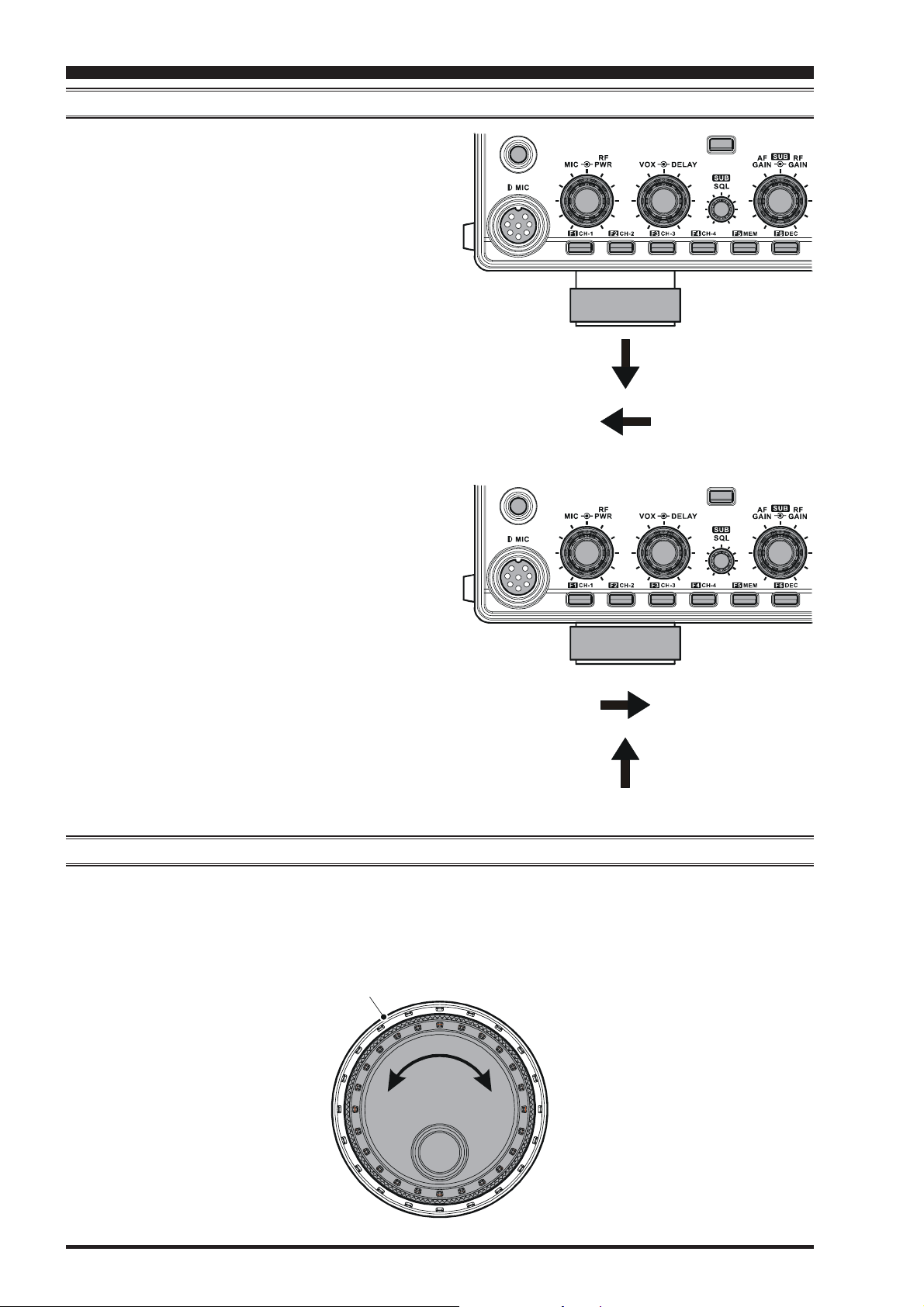
ADJUSTING THE MAIN TUNING DIAL TORQUE
The torque (drag) of the Main Tuning Dial knob may be
adjusted according to your preferences. Simply hold down
the rear skirt of the knob, and while holding it in place
rotate the knob itself to the right to reduce the drag or to
the left to increase the drag.
Hold the Skirt
TIGHTEN
c
d
LOOSEN
Page 6 FT-2000D OPERATING MANUAL
Page 9
BEFORE YOU BEGIN
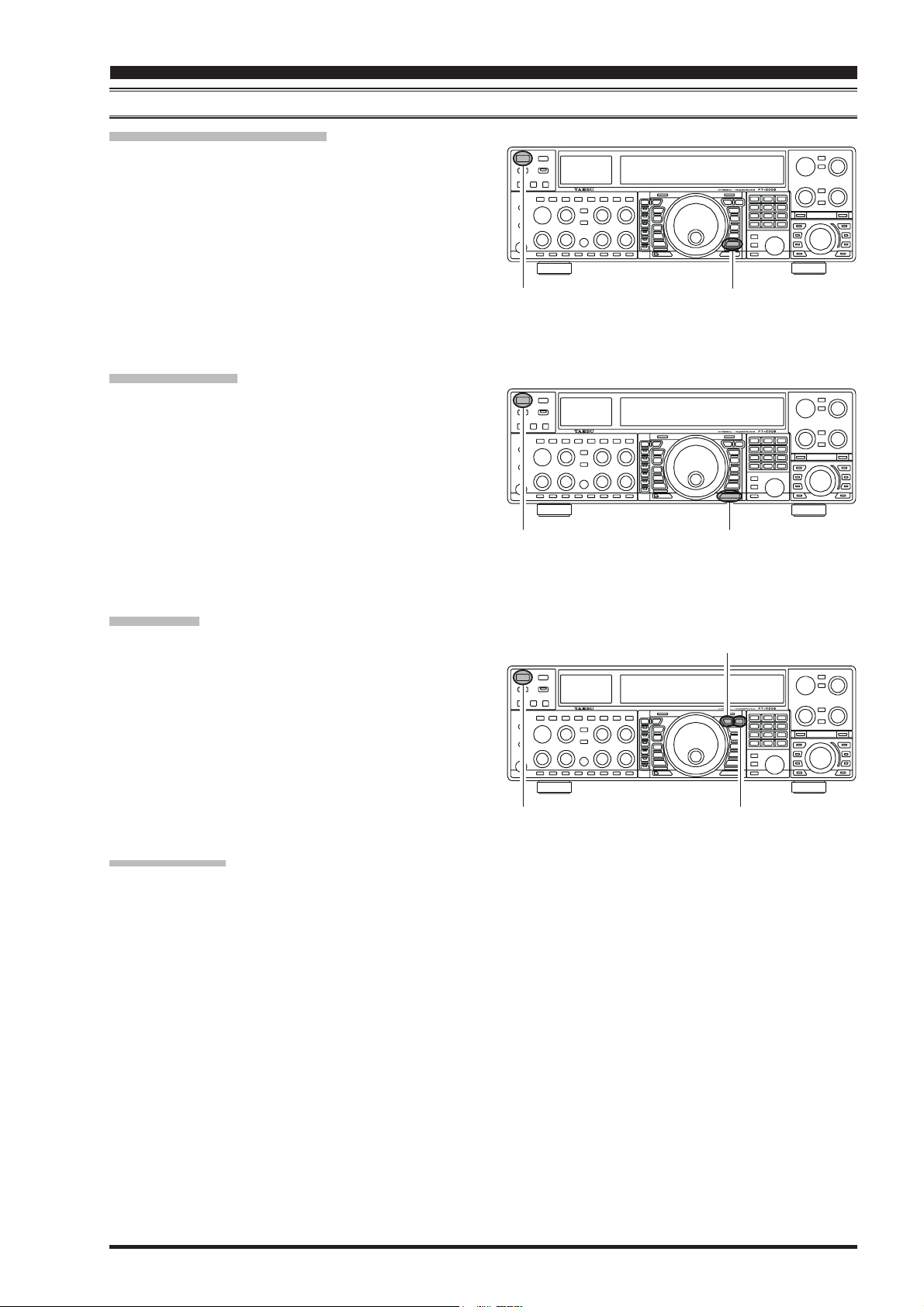
RESETTING THE MICROPROCESSOR
RESETTING MEMORIES (ONLY
)
Use this procedure to reset (clear out) the Memory channels previously stored, without affecting any configuration changes you may have made to the Menu settings.
1. Press the front panel’s [POWER] switch to turn the
transceiver off.
XX
X
2. Press and hold in the [A
XX
M] button; while holding it
in, press and hold in the front panel’s [POWER] switch
to turn the transceiver on. Once the transceiver comes
XX
X
on, you may release the [A
XX
M] button.
MENU RESETTING
Use this procedure to restore the Menu settings to their
factory defaults, without affecting the memories you have
programmed.
1. Press the front panel’s [POWER] switch to turn the
transceiver off.
2. Press and hold in the [MENU] button; while holding it
in, press and hold in the front panel’s [POWER] switch
to turn the transceiver on. Once the transceiver comes
on, you may release the [MENU] button.
[
POWER] button
[
POWER] button
XX
X
XX
[
A
M] button
[
MENU] button
FULL RESET
Use this procedure to restore all Menu and Memory settings to their original factory defaults. All Memories will
be cleared out by this procedure.
1. Press the front panel’s [POWER] switch to turn the
transceiver off.
2. Press and hold in the [FAST] and [LOCK] buttons;
while holding them in, press and hold in the front
panel’s [POWER] switch to turn the transceiver on.
Once the transceiver comes on, you may release the
other two switches.
IMPORTANT NOTE
When the optional DMU-2000 is connected and is
turned on the [POWER] switch, the DMU-2000’s data
is also reset when perform the full reset of the FT-
2000D.
When the optional RF uTUNE Kit is used, perform
the full reset of the FT-2000D after taking the optional
RF μTUNE Kit off.
[
POWER] button
[
FAST] button
[
LOCK] button
Page 7FT-2000D OPERATING MANUAL
Page 10
INSTALLATION AND INTERCONNECTIONS
ANTENNA CONSIDERATIONS
The FT-2000D is designed for use with any antenna system providing a 50 Ohm resistive impedance at the desired operating frequency. While minor excursions from the 50-Ohm specification are of no consequence, the transceiver’s Automatic Antenna Tuner may not be able to reduce the impedance mismatch to an acceptable value if the Standing Wave Ratio
(SWR) present at the Antenna jack is greater than 3:1.
Every effort should, therefore, be made to ensure that the impedance of the antenna system utilized with the FT-2000D be
as close as possible to the specified 50-Ohm value.
Note that the “G5RV” type antenna does not provide a 50-Ohm impedance on all HF Amateur bands, and an external widerange antenna coupler must be used with this antenna type.
Any antenna to be used with the FT-2000D must, ultimately, be fed with 50 Ohm coaxial cable. Therefore, when using a
“balanced” antenna such as a dipole, remember that a balun or other matching/balancing device must be used so as to
ensure proper antenna performance.
The same precautions apply to any additional (receive-only) antennas connected to the RX ANT jack; if your receive-only
antennas do not have an impedance near 50 Ohms at the operating frequency, you may need to install an external antenna
tuner to obtain optimum performance.
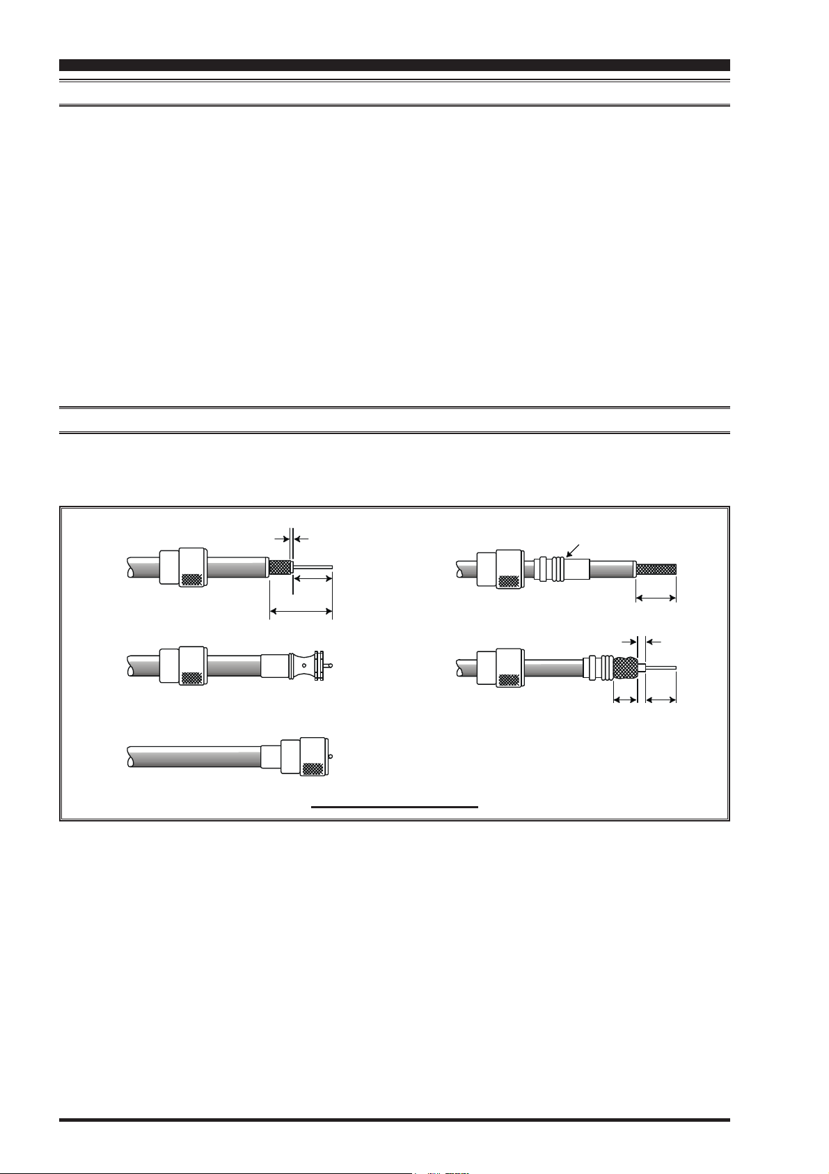
ABOUT COAXIAL CABLE
Use high-quality 50-Ohm coaxial cable for the lead-in to your FT-2000D transceiver. All efforts at providing an efficient
antenna system will be wasted if poor quality, lossy coaxial cable is used. This transceiver utilizes standard “M” (“PL-259”)
type connectors, except for the “RX OUT” BNC connector.
1/16''
Adapter
3/4''
3/4''
1 1/8''
1/8''
5/8''3/8''
TYPICAL PL-259 INSTALLATION
Page 8 FT-2000D OPERATING MANUAL
Page 11
INSTALLATION AND INTERCONNECTIONS
GROUNDING
The FT-2000D transceiver, like any other HF communications apparatus, requires an effective ground system for maximum electrical safety and best communications effectiveness. A good ground system can contribute to station efficiency in
a number of ways:
It can minimize the possibility of electrical shock to the operator.
It can minimize RF currents flowing on the shield of the coaxial cable and the chassis of the transceiver; such currents
may lead to radiation which can cause interference to home entertainment devices or laboratory test equipment.
It can minimize the possibility of erratic transceiver/accessory operation caused by RF feedback and/or improper cur-
rent flow through logic devices.
An effective earth ground system may take several forms; for a more complete discussion, see an appropriate RF engineering text. The information below is intended only as a guideline.
Typically, the ground connection consists of one or more copper-clad steel rods, driven into the ground. If multiple ground
rods are used, they should be positioned in a “V” configuration, and bonded together at the apex of the “V” which is nearest
the station location. Use a heavy, braided cable (such as the discarded shield from type RG-213 coaxial cable) and strong
cable clamps to secure the braided cable(s) to the ground rods. Be sure to weatherproof the connections to ensure many
years of reliable service. Use the same type of heavy, braided cable for the connections to the station ground bus (described
below).
Inside the station, a common ground bus consisting of a copper pipe of at least 25 mm (1”) diameter should be used. An
alternative station ground bus may consist of a wide copper plate (single-sided circuit board material is ideal) secured to the
bottom of the operating desk. Grounding connections from individual devices such as transceivers, power supplies, and
data communications devices (TNCs, etc.) should be made directly to the ground bus using a heavy, braided cable.
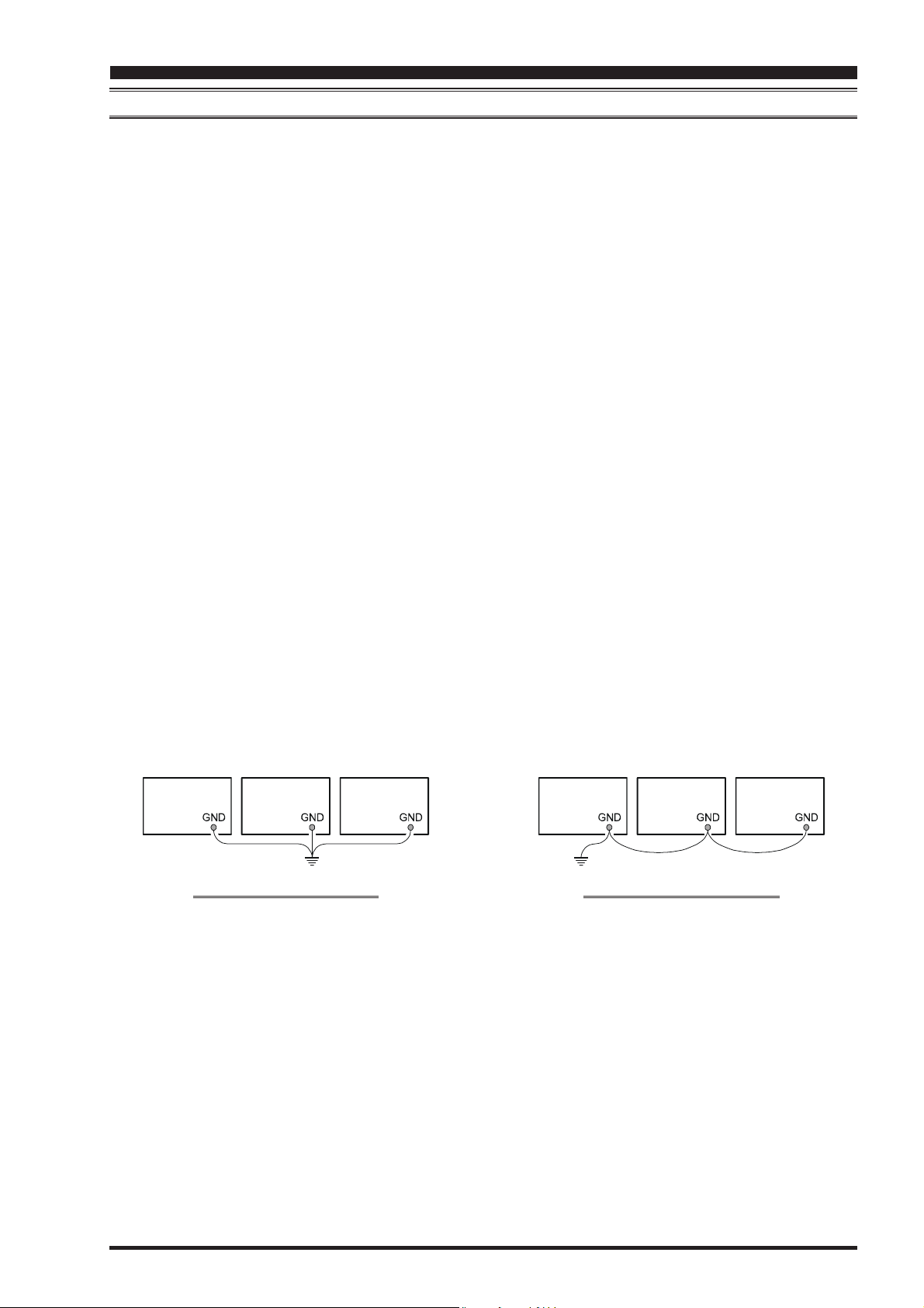
Do not make ground connections from one electrical device to another, and thence to the ground bus. This so-called “DaisyChain” grounding technique may nullify any attempt at effective radio frequency grounding. See the drawing below for
examples of proper grounding techniques.
Inspect the ground system - inside the station as well as outside - on a regular basis so as to ensure maximum performance
and safety.
Besides following the above guidelines carefully, note that household or industrial gas lines must never be used in an
attempt to establish an electrical ground. Cold water pipes may, in some instances, help in the grounding effort, but gas lines
represent a significant explosion hazard, and must never be used.
Transceiver
PROPER GROUND CONNECTION
Linear
Amplifier
TNC
Transceiver
IMPROPER GROUND CONNECTION
Linear
Amplifier
"Daisy Chain"
TNC
Page 9FT-2000D OPERATING MANUAL
Page 12
INSTALLATION AND INTERCONNECTIONS
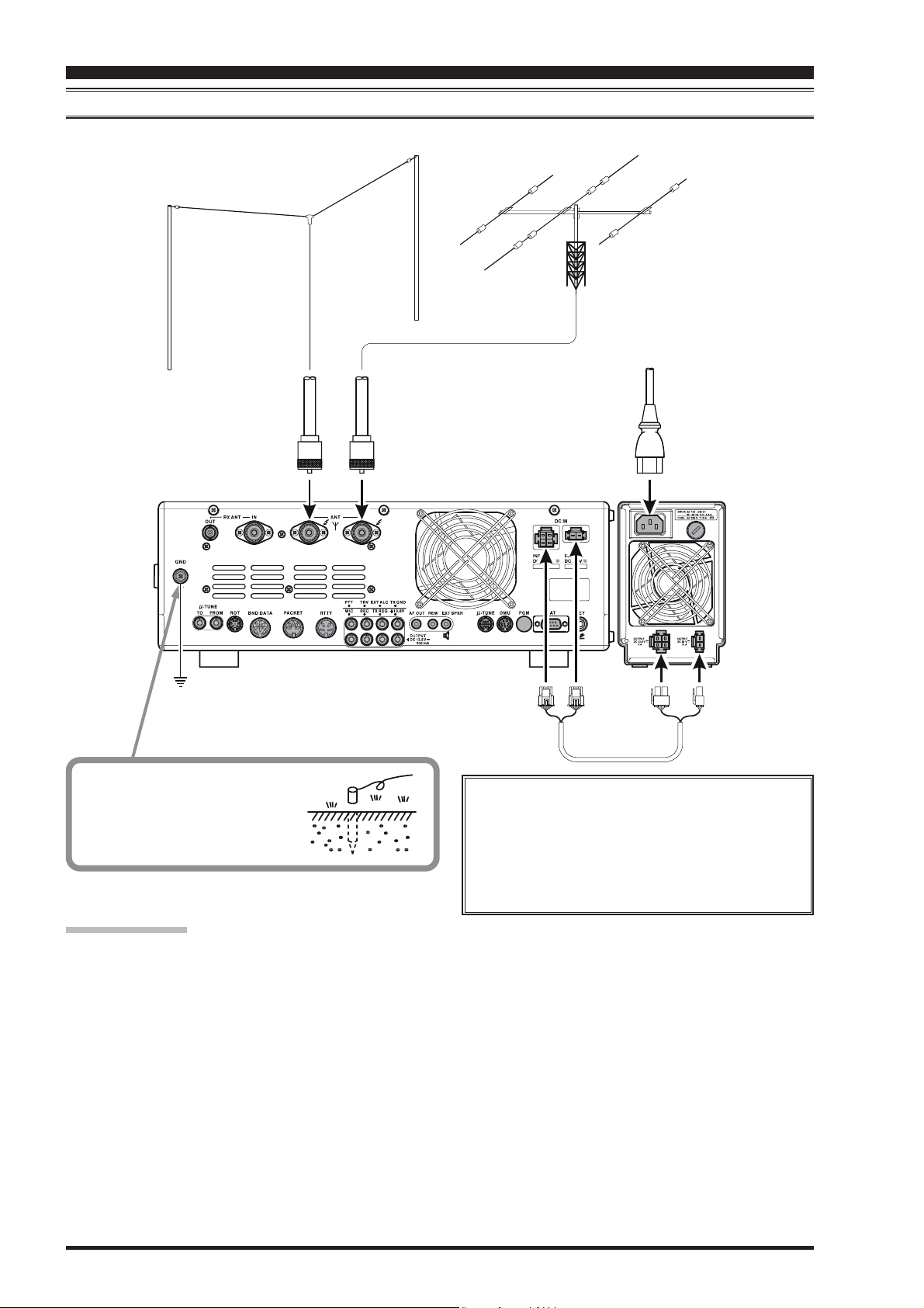
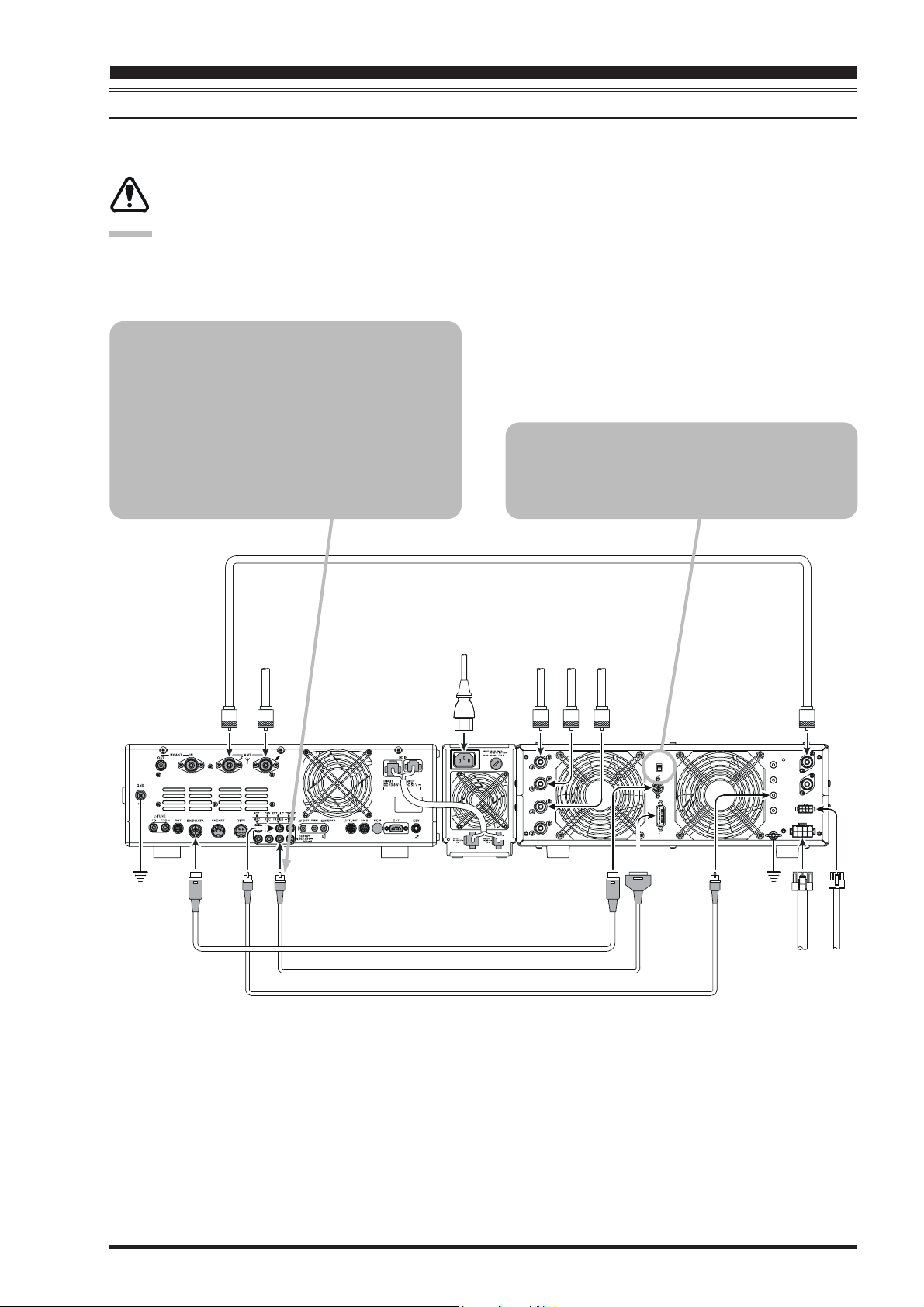
CONNECTION OF ANTENNA AND FP-2000 POWER SUPPLY
Please refer to the illustration for the proper connection of the antenna coaxial cables and the FP-2000 Power Supply.
Use a short, thick, braided cable
to connect your station equipment
to the buried ground rod (or alternative earth ground system).
”
1
"
A
N
N
E
T
N
A
”
2
"
A
N
N
E
T
N
A
NOTE
Be sure that the FT-2000D’s [POWER] switch and
the FP-2000’s [POWER] switch are both turned
off before you plug or unplug any power cable to/
from the FP-2000. This will avoid the possibility
of potentially-damaging spikes or electrical shock.
IMPORTANT NOTE:
Do not position this apparatus in a location with direct exposure to sunshine.
Do not position this apparatus in a location exposed to dust and/or high humidity.
Do not place equipment, books, or papers on top of the transceiver. Also, provide a few centimeters of space on either
side of the transceiver.
Ensure adequate ventilation around this apparatus, so as to prevent heat build-up and possible reduction of performance
due to high heat.
Do not install this apparatus in a mechanically-unstable location, or where objects may fall onto this product from
above.
To minimize the possibility of interference to home entertainment devices, take all precautionary steps including sepa-
ration of TV/FM antennas from Amateur transmitting antennas to the greatest extent possible, and keep transmitting
coaxial cables separated from cables connected to home entertainment devices.
Ensure that the AC power cord is not subject to undue stress or bending, which could damage the cable or cause it to be
accidentally unplugged from the rear panel AC input jack.
Be absolutely certain to install your transmitting antenna(s) such that they cannot possibly come in contact with TV/FM
radio or other antennas, nor with outside power or telephone lines.
Page 10 FT-2000D OPERATING MANUAL
Page 13
INSTALLATION AND INTERCONNECTIONS
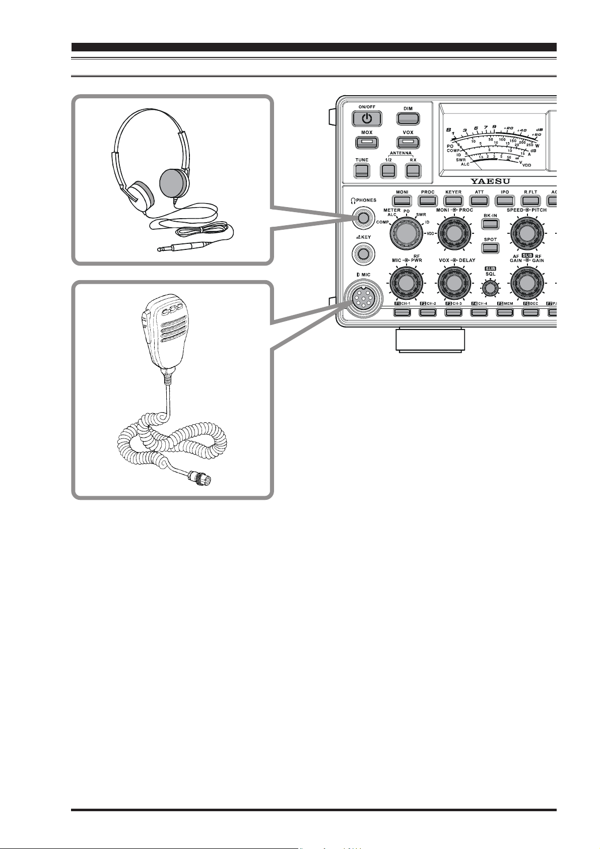
CONNECTION OF MICROPHONE AND HEADPHONE
Page 11FT-2000D OPERATING MANUAL
Page 14
INSTALLATION AND INTERCONNECTIONS
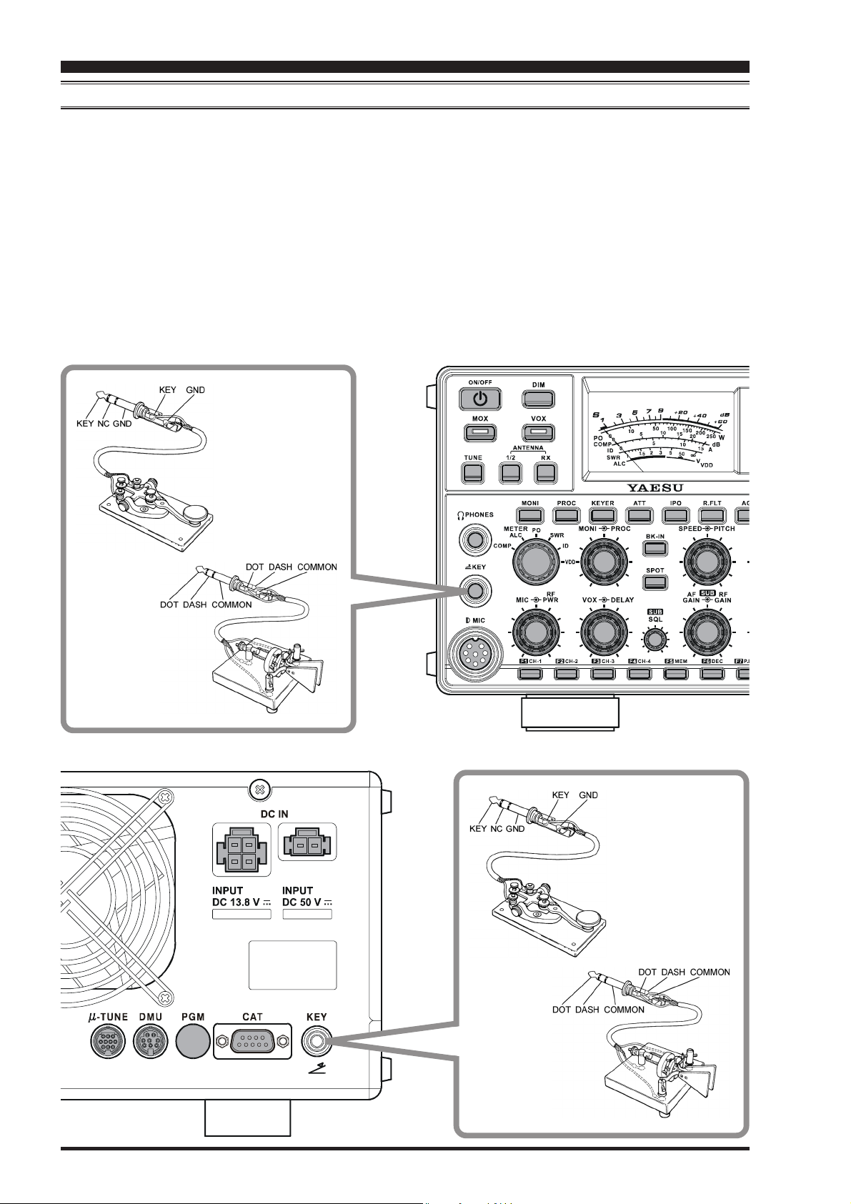
KEY, KEYER, AND COMPUTER-DRIVEN KEYING INTERCONNECTIONS
The FT-2000D includes a host of features for the CW operator, the functions of which will be detailed in the “Operation”
section later. Besides the built-in Electronic Keyer, two key jacks are provided, one each on the front and rear panels, for
convenient connection to keying devices.
The Menu system allows you to configure the front and rear panel KEY jacks according to the device you wish to connect.
For example, you may connect your keyer paddle to the front panel KEY jack, and use Menu item “054 A1A F-TYPE” for
paddle input, while connecting the rear panel’s KEY jack to the keying line from your personal computer (which emulates
a “straight key” for connection purposes), and configure the rear panel jack using Menu item “056 A1A R-TYPE.”
Both KEY jacks on the FT-2000D utilize “Positive” keying voltage. Key-up voltage is approximately +5V DC, and keydown current is approximately 1 mA. When connecting a key or other device to the KEY jacks, use only a 3-pin (“stereo”)
1/4” phone plug; a 2-pin plug will place a short between the ring and (grounded) shaft of the plug, resulting in a constant
“key-down” condition in some circumstances.
Page 12 FT-2000D OPERATING MANUAL
Page 15
INSTALLATION AND INTERCONNECTIONS
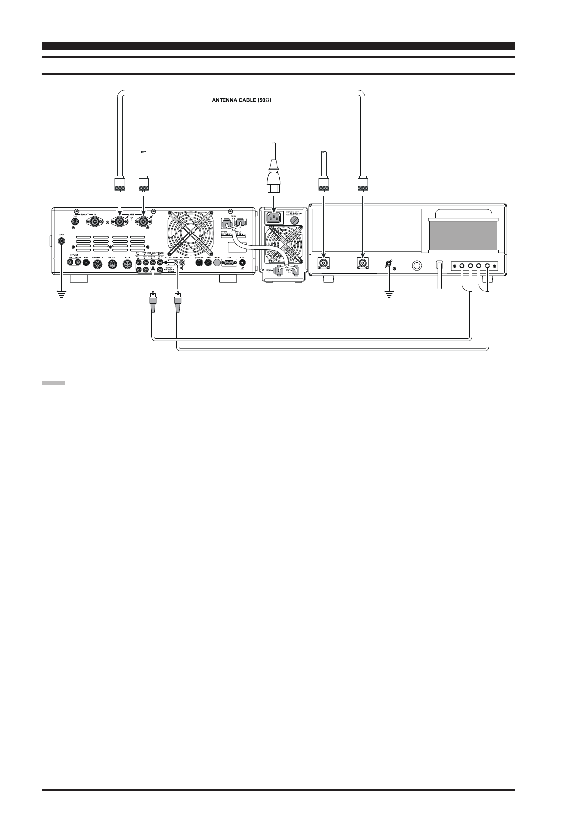
VL-1000 LINEAR AMPLIFIER INTERCONNECTIONS
Be sure that both the FT-2000D and VL-1000 are turned off, then follow the installation recommendations contained in
the illustration.
Set the “ATT” switch to the “ON” position on the front panel of the VL-1000. The 200-Watt power output
from the FT-2000D is far in excess of that which is required to drive the VL-1000 to its full rated output.
NOTE:
Refer to the VL-1000 Operating Manual for details regarding amplifier operation.
Do not attempt to connect or disconnect coaxial cables when your hands are wet.
About the CONTROL Cable
The VL-1000 may be operated with the FT2000D whether or not the CONTROL Cable is
connected; however, the CONTROL Cable allows you to tune up the amplifier automatically
by just pressing the [F SET] or [TUNE] key on
the VL-1000 to transmit a carrier for tuning purposes.
To link the FT-2000D and VL-1000 Power
switches, set the VL-1000 REMOTE switch to
the “ON” position.
ANTENNA CABLE (Not Supplied)
a
n
n
e
t
n
A
z
H
M
0
5
2
1
T
T
N
N
A
A
A
T
A
D
D
N
A
B
C
Q
L
E
A
R
T
X
X
T
E
BAND DATA CABLE Supplied w/VL-1000
CONTROL CABLE (Supplied w/VL -1000
N
I
C
A
~
()
ALC CABLE (Supplied w/VL -1000
a
a
n
n
e
t
n
A
l
a
c
i
t
r
e
V
F
H
1
T
N
A
ANT 1
ANT 2
ANT 3
ANT 4
a
n
n
n
n
e
e
t
t
n
n
A
A
e
l
m
o
a
p
e
i
B
D
F
F
H
H
1
INPUT 1
INPUT 2
N
I
V
8
4
C
D
CONTROL
DC48V IN
¾
T
U
P
N
I
L
O
R
T
N
O
C
0
0
0
0
0
0
1
1
-
-
P
P
V
V
¾
2
3
T
T
N
N
A
A
REMOTE
ON
OFF
BAND DATA 1
BAND DATA 2
1
A
T
A
D
D
N
A
B
)
)
2
A
T
A
D
D
N
A
B
PTT 1
PTT 2
ALC 1
ALC 2
GND
1
D
C
N
L
G
A
Page 13FT-2000D OPERATING MANUAL
Page 16
INSTALLATION AND INTERCONNECTIONS
INTERFACING TO OTHER LINEAR AMPLIFIERS
a
n
n
e
t
n
A
z
H
M
0
5
2
1
T
T
N
N
A
A
N
I
C
A
~
a
n
n
e
t
n
A
F
H
1
1
T
N
A
T
U
P
N
I
D
D
N
G
C
L
N
A
G
T
X
X
T
E
NOTE
The TX/RX switching in the linear amplifier is con-
trolled by switching components in the transceiver. The
relay circuit of the FT-2000D used for this switching
is capable of switching AC voltage of 100 Volts at up
to 300 mA, or DC voltages or 60 V at 200 mA or 30 V
at up to 1 Amp. In order to engage the switching relay,
use Menu item “146 tGEn ETX-GND;” set this Menu
item to “
EnAEnA
EnA (Enable)” to activate the amplifier switch-
EnAEnA
ing relay.
The specified range for ALC voltage to be used with
the FT-2000D is 0 to –4 Volts DC.
Amplifier systems utilizing different ALC voltages will
not work correctly with the FT-2000D, and their ALC
lines must not be connected if this is the case.
RF INRF OUT
D
N
G
ACFUSEGND
EERYALC
Page 14 FT-2000D OPERATING MANUAL
Page 17

PLUG /CONNECTOR PINOUT DIAGRAMS
MIC CAT
UP
+5V
DOWN
FAST
GND
PTT
MIC GND
MIC
(as viewed from front panel)
DC IN 50 V PACKET
RTTY
(as viewed from rear panel)
BAND DATA
(as viewed from rear panel)(as viewed from rear panel)
ROT ROTATOR
()
N/A
SERIAL OUT
SERIAL IN
N/A
GND
N/A
RTS
CTS
NC
+13V
TX GND
GND
BAND DATA A
BAND DATA B
BAND DATA C
BAND DATA D
TX INH
DC IN 13. 8 V
(as viewed from rear panel)
(as viewed from rear panel)
PHONE
DATA IN
GND
PAC KET PT T
DATA OUT
BUSY
CW ROTATION
SHIFT
RX OUT
PTT
GND
(as viewed from rear panel)
REM REMOTE
SIGNAL
()
GND
(as viewed from rear panel)
AF OUT
MAIN (VFO-A) GND
CCW ROTATION
SPEED
DIRECTION
GND
NC
SUB (VFO-B
)
RCA PLUG KEY
For Internal Keyer
(--)-
GND or
SUB (VFO-B
MAIN (VFO-A) GND
EXT SPKR
GND
SIGNAL
For Straight Key
)
SIGNAL or
()
+
DOT DASH COMMON
KEY GND
Do not use
2-conductor type plug
IMPORTANT NOTE:
The μ-TUNE, DMU, and PGM connectors are special connectors for this transceiver. Please do not connect any accessory
or other device not specifically approved by Vertex Standard. Failure to observe this precaution may cause damage not
covered by the Limited Warranty on this apparatus.
Page 15FT-2000D OPERATING MANUAL
Page 18
FRONT PANEL CONTROLS & SWITCHES
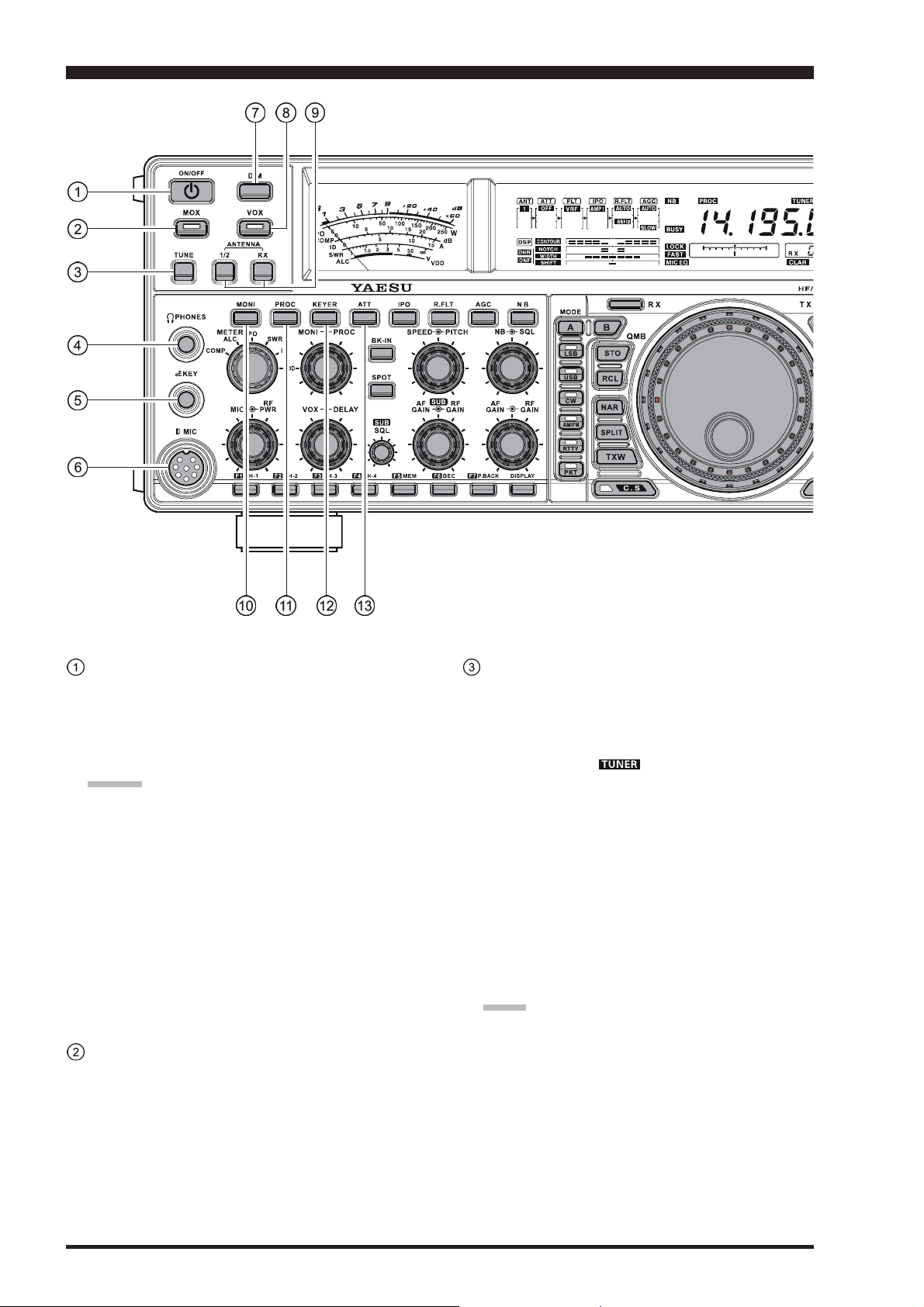
POWER Switch
Press and hold in this switch for one second to turn the
transceiver on. Similarly, press and hold in this switch
for one second to turn the transceiver off. (The FP-
2000’s [POWER] switch must also be set to on “I”
before this switch will function.)
ADVICE:
The main power switch for the system is located
on the front panel of the FP-2000 Power Supply.
When the FP-2000 main power switch is pushed
down on the “I” side, the FP-2000 is turned on,
and the FT-2000D is placed in the “standby” state.
If the FP-2000 main power switch is not turned
on, it is not possible to turn on the FT-2000D transceiver. For more details about the main power
switch location on the FP-2000, please see the discussion on page 34.
If you press this switch momentarily while the trans-
ceiver is turned on, the transceiver’s audio will be
muted for three seconds.
MOX Switch
Pressing this button engages the PTT (Push to Talk) circuit, to activate the transmitter (the LED inside this button will glow red). It must be turned off (the red LED
will be off) for reception. This button replicates the action of the Push to Talk (PTT) switch on the microphone.
When engaging the [MOX] button (the LED inside this
button glows red) or otherwise causing a transmission to
be started, be certain you have either an antenna or 50Ohm dummy load connected to the selected Antenna jack.
TUNE Switch
This is the on/off switch for the FT-2000D’s Auto-
matic Antenna Tuner.
Pressing this button momentarily places the antenna
tuner in line between the transmitter final amplifier and
the antenna jack (“ ” icon will appear in the display). Reception is not affected.
Pressing and holding in this button for 1/2 second, while
receiving in an amateur band, activates the transmitter
for a few seconds while the automatic antenna tuner
rematches the antenna system impedance for minimum
SWR. The resulting setting is automatically stored in
one of the antenna tuner’s 100 memories, for instant
automatic recall later when the receiver is tuned near
the same frequency.
Pressing this button momentarily, while the Tuner is
engaged, will take the Automatic Antenna tuner out of
the transmit line.
NOTE:
When the Automatic Antenna Tuner is tuning itself, a
signal is being transmitted. Therefore, be absolutely
certain that an antenna or dummy load is connected to
the selected antenna jack before pressing and holding
in the [TUNE] button to start antenna tuning.
Page 16 FT-2000D OPERATING MANUAL
Page 19
FRONT PANEL CONTROLS & SWITCHES
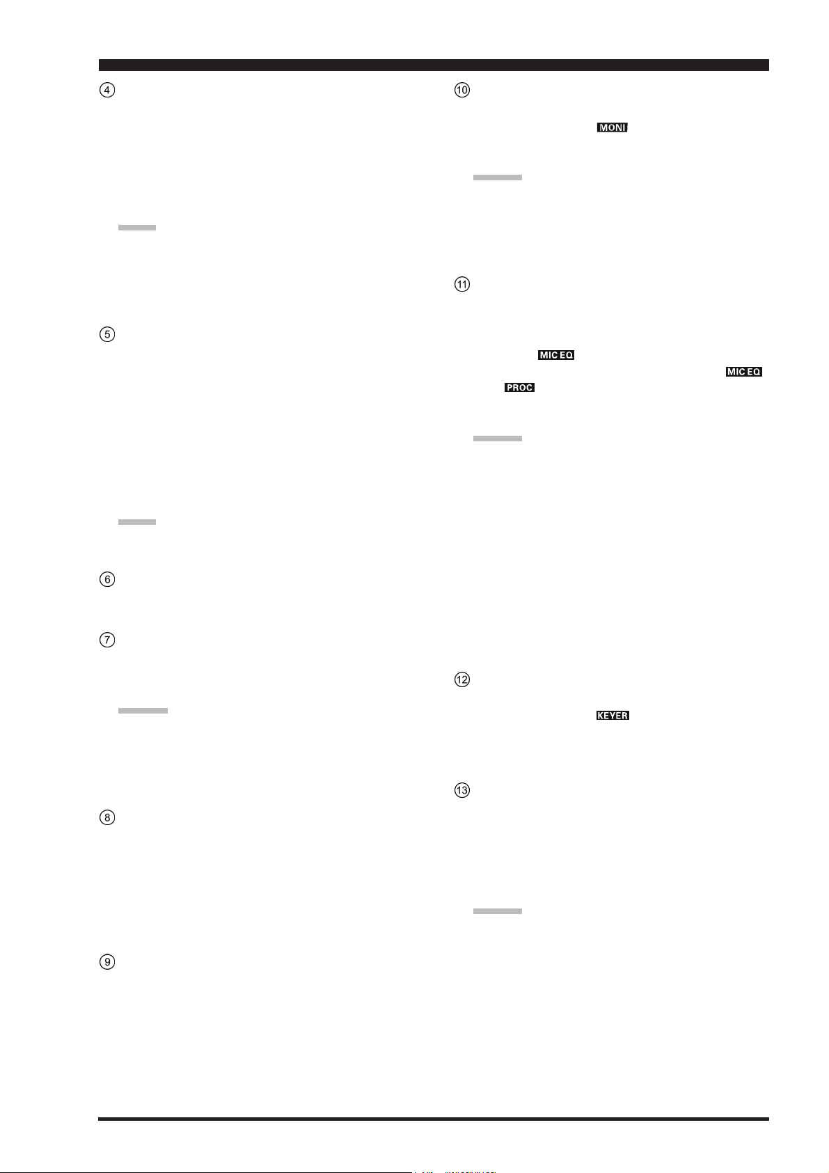
PHONES Jack
A 1/4-inch, 3-contact jack accepts either monaural or
stereo headphones with 2- or 3-contact plugs. When a
plug is inserted, the loudspeaker is disabled. With stereo headphones such as the optional YH-77STA, you
can monitor both Main (VFO-A) and Sub (VFO-B)
receiver channels at the same time during Dual Receive operation.
NOTE:
When wearing headphones, we recommend that you
turn the AF Gain levels down to their lowest settings
before turning power on, to minimize the impact on
your hearing caused by audio “pops” during switchon.
KEY Jack
This 1/4-inch, 3-contact jack accepts a CW key or keyer
paddles (for the built-in electronic keyer), or output
from an external electronic keyer. Pinout is shown on
page 15. Key up voltage is 5 V, and key down current
is 1 mA. This jack may be configured for keyer, “Bug,”
“straight key,” or computer keying interface operation
via Menu item “054 A1A F-TYPE” (see page 121).
There is another jack with the same name on the rear
panel, and it may be configured independently for Internal Keyer or pseudo-straight-key operation.
NOTE:
You cannot use a 2-contact plug in this jack (to do so
produces a constant “key down” condition).
Microphone Connector
This 8-pin jack accepts input from a microphone utilizing a traditional YAESU HF-transceiver pinout.
DIM Switch
Press this button to lower the illumination intensity of
the analog meter and the frequency display. Press it
once more to restore full brightness.
AA
A
AA
Menu Items “008 diSP DIM MTR” and “009 diSP
DIM VFD” allow you to configure the dimming lev-
els for the analog meter and the frequency display independently, so you can customize the brightness levels.
DD
VICEVICE
D
VICE
DD
VICEVICE
::
:
::
VOX Switch
This button enables automatic voice-actuated transmitter switching in the SSB, AM, and FM modes. While
activated, the LED inside this button glows red. The
controls affecting VOX operation are the front panel’s
[
VOX] and [DELAY] knobs. By proper adjustment of
these controls, hands-free voice-actuated operation is
possible.
ANTENNA Select Switch
[
1/2]: Pressing this selects either the ANT 1 or 2 jack
on the rear panel, and allows convenient antenna
switching at the press of button. The selected antenna
jack is indicated at the upper left corner of the display.
[RX]
: Normally, the antenna connected to the ANT 1
or 2 jack is used for receive (and always used for transmit). When the [RX] switch is pressed, an antenna connected to the RX ANT will be used during receive.
MONI (Monitor) Switch
This button enables the transmit monitor in all modes.
While activated, the “ ” icon appears in the display. Adjustment of the Monitor level is accomplished
using the [MONI] knob.
ADVICE:
When using headphones, the Monitor is highly useful
for making adjustments to the Parametric Equalizer or
other voice quality adjustments, because the voice quality heard in the headphones is such a “natural” reproduction of the transmitted audio quality.
PROC (Processor) Switch
This button enables the Parametric Microphone Equalizer and Speech Processor for SSB/AM transmission.
When the Parametric Microphone Equalizer is activated, the “ ” icon appears in the display.
When the Speech Processor is activated, the “ ”
and “ ” icons appear in the display. Adjustment
of the Processor level is accomplished using the
[
PROC] knob.
ADVICE:
The Speech Processor is a tool for increasing the
average power output through a compression technique. However, if the [PROC] knob is advanced
too far, the increase in compression becomes
counter-productive, as intelligibility will suffer. We
recommend that you monitor the sound of your signal using the Monitor (with headphones).
When the optional DMU-2000 Data Management
Unit is connected, you may use the Audio Scope/
Oscilloscope page to help you adjust the setting of
the compression level of the Speech Processor for
optimum performance using your voice and microphone.
KEYER Switch
This button toggles the internal CW keyer on and off.
While activated, the “ ” icon appears in the display. The Keyer sending speed and the CW Hang Time
are adjusted via the front panel’s [SPEED] and [DE-
LAY] knobs.
ATT Switch
This button selects the degree of attenuation, if any, to
be applied to the receiver input.
Available selections are –6 dB, –12 dB, –18 dB, or
OFF, and the selected attenuation level appears in the
ATT column of the Receiver Configuration Indicator
on the display.
ADVICE
The Attenuator affects both the Main (VFO-A) and
The Attenuator may be used in conjunction with
::
:
::
Sub (VFO-B) receivers.
the [IPO] switch to provide two stages of signal
reduction when an extremely strong signal is being
received.
Page 17FT-2000D OPERATING MANUAL
Page 20
FRONT PANEL CONTROLS & SWITCHES
IPO (INTERCEPT POINT OPTIMIZATION) Switch
This button may be used to set the optimum front end
characteristics of the receiver circuit for a very strongsignal environment. Available selections are AMP 1
(low distortion amplifier), AMP 2 (2-stage low-distortion RF amplifier), or ON (bypasses the front end RF
amplifier), and the selected receiver RF amplifier appears at the IPO column of the Receiver Configuration
Indicator in the display.
ADVICE:
The IPO switch affects both the Main (VFO-A) and
Sub (VFO-B) receivers.
R.FLT Switch
This button selects the bandwidth for the Main Band
(VFO-A) receiver’s first IF Roofing Filter. Available
selections are 3 kHz, 6 kHz, 15 kHz, or Auto, and the
selected bandwidth appears in the FLT column of the
Receiver Configuration Indicator on the display.
ADVICE:
The Roofing Filter selection applies to the Main
band (VFO-A) only.
Because the roofing filter is in the first IF, the pro-
tection it provides against interference is quite significant. When set to AUTO, the SSB bandwidth is
6 kHz, while CW is 3 kHz and FM/RTTY are 15
kHz. On a crowded SSB band, however, you may
wish to select the 3 kHz filter, for the maximum
possible interference rejection.
AGC Switch
This button selects the AGC characteristics for the receiver. Available selections are FAST, MID, SLOW,
or AUTO, and the “AGC” icon will change according
to the AGC characteristics selected.
Press the [AGC] button repeatedly to select the desired receiver-recovery time constant. Press and hold
in the [AGC] button for two seconds to disable the
AGC (for testing or weak-signal reception).
When the [AGC] button is pressed independently, it
applies to the Main band (VFO-A) receiver.
When you press the [B] button, followed by the [AGC
button (within five seconds of pressing the [B] switch),
it affects the Sub band (VFO-B) receiver.
ADVICE:
If the AGC receiver-recovery time is set to “
pressing and holding in the [AGC] button, the S-meter
will no longer deflect. Additionally, you will likely encounter distortion on stronger signals, as the IF amplifiers and the following stages are probably being overloaded.
OffOff
Off” by
OffOff
]
Page 18 FT-2000D OPERATING MANUAL
Page 21
FRONT PANEL CONTROLS & SWITCHES
NB Switch
This button turns the IF Noise Blanker on and off.
Press this button momentarily to reduce a short-duration pulse noise; the “ ” icon will appear in the display.
Press and hold in this button for one second to reduce
a longer-duration man-made pulse noise; the “ ”
icon will blink for three seconds, then will appear continuously in the display.
Press this button again to disable the noise blanker;
the “ ” icon will disappear.
ADVICE:
When you press (or press and hold) the [NB] button
momentarily, it affects the Main band (VFO-A) receiver. When you press the [B] button, then press (or
press and hold in) the [NB] button (within five seconds of pressing the [B] button), it affects the Sub band
(VFO-B) receiver.
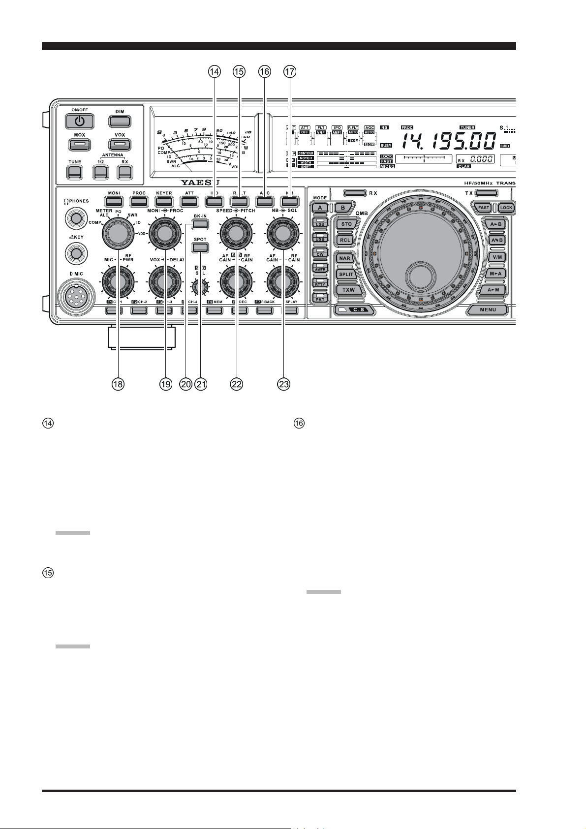
METER Switch
This control switch determines the function of the meter
during transmission.
COMP: Indicates the speech compressor level (SSB
mode only).
ALC: Indicates the relative ALC voltage.
PO: Indicates the average power output level.
SWR: Indicates the Standing Wave Ratio (Forward:
Reflected).
ID: Indicates the final amplifier drain current.
VDD: Indicates the final amplifier drain voltage.
MONI PROC Knobs
MONI Knob
The inner [MONI] knob adjust the audio level of the
transmit monitor during transmission (relative to the
AF GAIN control), when activated by the [MONI
button.
PROC Knob
The outer [PROC] knob sets the compression (input)
level of the transmitter Speech Processor in the SSB,
AM, and FM modes, when activated by the [PROC
button.
ADVICE:
The Sub band (VFO-B) frequency display will show
the compression level of the Speech Processor for 3
seconds whenever the outer [PROC] knob is turned.
You may disable this feature (displaying the compression level) via Menu item “015 diSP LVL IND.” See
page 117 for details.
BK-IN Switch
This button turns the CW break-in capability on and
off. While the CW break-in is activated, the “ ”
icon appears in the display.
SPOT Switch
This button turns on the CW receiver spotting tone; by
matching the SPOT tone to that of the incoming CW
signal (precisely the same pitch), you will be “zero
beating” your transmitted signal on to the frequency of
the other station.
The Sub (VFO-B) frequency display will indicate the
offset tone frequency when this button is pressed.
SPEED PITCH Knobs
SPEED Knob
The inner [SPEED] knob adjusts the keying speed of
the internal CW keyer (4 ~ 60 WPM). Clockwise rotation increases the sending speed.
When turning this knob while pressing the [KEYER
button, the Sub (VFO-B) frequency display shows the
keying speed.
ADVICE:
The Sub band (VFO-B) frequency display will show
the keying speed for 3 seconds whenever the inner
[
SPEED] knob is turned.
You may disable this feature (displaying the keying
speed) via Menu item “015 diSP LVL IND.” See page
117 for details.
PITCH Knob
The outer [PITCH] knob selects your preferred CW
tone pitch (from 300 ~ 1050 Hz, in 50 Hz increments).
The Tx sidetone, receiver IF passband, and display
offset from the BFO (carrier) frequency are all affected
simultaneously. The Pitch control setting also affects
the operation of the CW Tuning Indicator, as the center frequency of the CW Tuning Indicator will follow
the setting of this control.
ADVICE:
]
]
The Sub band (VFO-B) frequency display will show
the CW tone pitch frequency for 3 seconds whenever
the outer [PITCH] knob is turned.
You may disable this feature (displaying the CW tone
pitch frequency) via Menu item “015 diSP LVL IND.”
See page 117 for details.
]
NB SQL Knobs
NB Knob
The inner [NB] knob adjusts the noise blanking level
when the (analog) IF noise blanker is activated by pressing the [NB] button.
SQL Knob
The outer [SQL] knob sets the signal level threshold
at which the Main (VFO-A) receiver audio is muted,
in all modes. It is very useful during local rag-chews,
to eliminate noise between incoming transmissions.
This control is normally kept fully counter-clockwise
(off), except when scanning and during FM operation.
Page 19FT-2000D OPERATING MANUAL
Page 22
FRONT PANEL CONTROLS & SWITCHES
MIC RF PWR Knobs
MIC Knob
The inner [MIC] knob adjusts the microphone input
level for (non-processed) SSB transmission.
ADVICE:
If you adjust the MIC Gain while speaking in a
somewhat-louder-than-normal voice level, watch
the ALC level and adjust the MIC Gain so that the
ALC reaches just to the right edge of the ALC scale.
Then, when you speak in a more normal voice level,
you’ll be certain not to be over-driving the mic amplifier stage.
The Sub band (VFO-B) frequency display will show
the relative microphone gain level for 3 seconds
whenever the outer [RF PWR] knob is turned.
You may disable this feature (displaying the relative microphone gain level) via Menu item “015
diSP LVL IND.” See page 117 for details.
RF PWR Knob
The outer [RF PWR] knob is the main RF Power output control for the transceiver, active in all operating
modes. Clockwise rotation increases the power output. Adjust this control for the desired power output
from the FT-2000D.
ADVICE:
The Sub band (VFO-B) frequency display will show
the RF Power output for 3 seconds whenever the outer
[
RF PWR] knob is turned.
You may disable this feature (displaying the RF Power
output) via Menu item “015 diSP LVL IND.” See page
117 for details.
VOX DELAY Knobs
VOX Knob
The inner [VOX] knob sets the gain of the VOX circuit, to set the level of microphone audio needed to
activate the transmitter during voice operation while
the [VOX] switch is engaged. The [VOX] switch must
be switched “ON” to engage the VOX circuit.
DELAY Knob
The outer [DELAY] knob sets the hang time of the
VOX circuit for voice operation and keying delay for
CW operation.
During voice operation, this knob sets the hang time,
between the moment you stop speaking, and the automatic switch from transmit back to receive. Adjust this
for smooth VOX operation, so the receiver is only activated when your transmission is ended and you wish
to receive.
For CW operation, this knob sets the keying delay,
between the moment you stop sending, and the automatic switch from transmit back to receive during
“Semi-break-in” operation. Adjust this just long enough
to prevent the receiver from being restored during word
spaces at your preferred sending speed.
ADVICE:
The Sub band (VFO-B) frequency display will show
the hang time of the VOX circuit for 3 seconds whenever the outer [DELAY] knob is turned.
You may disable this feature (displaying the hang time
of the VOX circuit) via Menu item “015 diSP LVL
IND.” See page 117 for details.
Page 20 FT-2000D OPERATING MANUAL
Page 23
FRONT PANEL CONTROLS & SWITCHES
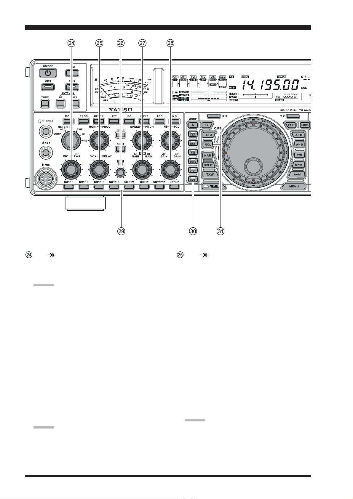
SUB SQL Knob
This knob sets the signal level threshold at which Sub
(VFO-B) receiver audio is muted, in all modes. It is
very useful during local rag-chews, to eliminate noise
between incoming transmissions. This control is normally kept fully counter-clockwise (off), except when
scanning and during FM operation.
SUB AF GAIN SUB RF GAIN
AF GAIN Knob
The inner [SUB AF GAIN] knob sets the Sub (VFOB) receiver’s audio volume level. Typically, you will
operate with this control set between the 9 o’clock and
10 o’clock positions.
RF GAIN Knob
The outer [SUB RF GAIN] knob is the Sub (VFO-B)
receiver’s RF gain control, which adjusts the gain of
the Sub (VFO-B) receiver’s RF and IF amplifier stages.
This control is normally left in the fully clockwise position.
AF GAIN RF GAIN Knobs
AF GAIN Knob
The inner [AF GAIN] knob sets the Main (VFO-A)
receiver’s audio volume level. Typically, you will operate with this control set between the 9 o’clock and
10 o’clock positions.
RF GAIN Knob
The outer [RF GAIN] knob is the Main (VFO-A)
receiver’s RF gain control, which adjusts the gain of
the Main (VFO-A) receiver’s RF and IF amplifier
stages. This control is normally left in the fully clockwise position.
F1 - F7 / DISPLAY Keys
These keys can be used to control the Voice Memory
capability for the SSB/AM/FM modes, and the Contest Keyer for the CW mode. You can also play back
up to 15 seconds of incoming received audio, as well,
for verification of a missed callsign or other purposes.
When the optional DMU-2000 Data Management Unit
is connected, you can also use the “Function” keys for
the various functions associated with each “page” of
the external display’s capability.
[F1(
CH 1)] - [F4(CH 4)] key
In the case of Voice Memory, up to 20 seconds of audio may be stored on each channel. For CW messages,
up to 50 characters (“PARIS” specification) may be
stored into each channel. See page 76 (Voice Memory)
or page 88 (Contest Keyer) for details.
[F5(
MEM)] key
This key is pressed for the purpose of storing either a
Voice Memory or a Contest Keyer Memory channel’s
contents. See page 76 (Voice Memory) or page 88
(Contest Keyer) for details.
[F6(
DEC)] key
When utilizing the sequential contest number capability
of the Contest Keyer, press this key to decrement (back
up) the current Contest Number by one digit (i.e. to back
up from #198 to #197, etc.). See page 91 for details.
[F7(
P.BACK)] key
Press and hold in this button for 2 seconds to activate
the recording feature of the internal Digital Voice Recorder. The Voice Recorder allows you to record the
Main band (VFO-A) receiver audio for the most-recent 15 seconds. While you’re recording the receiver
audio, the “ ” icon will appear in the display.
Press this button momentarily to stop the recording,
then press this button momentarily again to play back
the receiver audio for the most-recent 15 seconds of
reception before you stopped the recording.
While playing back the receiver audio, the “ ” icon
will appear in the display.
Press and hold in this button for 2 seconds again to
resume recording.
[
DISPLAY] key
Press and hold in this key for two seconds to cause the
[F1(
CH 1)] - [DISPLAY] keys to act as “Function”
keys for the optional DMU-2000 Data Management
Unit if connected.
MODE Switches
[A], [B]
Pressing the [A] or [B] button will illuminate the respective indicator imbedded within the switch, allowing adjustment of the operating mode on the Main
(VFO-A) or Sub (VFO-B) band. Usually, the [A] button glow Red, signifying that the Main band (VFO-A)
is being adjusted. Similarly, pressing the [B] button
will cause its indicator to blink Orange for five seconds, signifying Sub band (VFO-B) adjustment.
ADVICE:
When changing bands, confirm the [A] or [B] button
illumination status at first, then press the appropriate
[
on the proper (Main or Sub) band.
[
Pressing the [LSB], [USB], [CW], [AM/FM],
[
mode. Pressing the [CW], [AM/FM], [RTTY], or
[
alternate operating features that can be used on these
modes (covered later).
Switch
BAND] button, so as to change operating frequencies
LSB], [USB], [CW], [AM/FM], [RTTY], [PKT] Switch
RTTY], or [PKT] button will select the operating
PKT] button multiple times will switch between the
QMB (Quick Memory Bank) Switches
STO (Store) Button
Pressing this button copies operating information (frequency, mode, bandwidth, and also repeater direction/
shift frequency and CTCSS functions on the FM mode)
into consecutive QMB Memories.
RCL (Recall) Button
Pressing this button recalls one of up to five Quick
Memory Bank memories for operation.
Page 21FT-2000D OPERATING MANUAL
Page 24
FRONT PANEL CONTROLS & SWITCHES
CLAR
+
NAR (Narrow) Switch
In the SSB/CW modes on the Main band (VFO-A),
this button is used to set the bandwidth of the DSP
(digital) IF filters to a user-programmed bandwidth (default values are SSB: 1.8 kHz, CW: 500 Hz, and RTTY/
PKT(SSB): 300 Hz).
ADVICE: In the SSB mode, when [NAR] has been en-
gaged, the [WIDTH] knob will be disabled, although
the [SHIFT] knob still works normally.
In the SSB mode on the Sub Band (VFO-B), this button is used to toggle the receiver’s bandwidth between
wide (2.25 kHz) and narrow (1.10 kHz).
In the CW mode on the Sub Band (VFO-B), this button is used to toggle the receiver’s bandwidth between
wide (2.0 kHz) and narrow (1.2 kHz).
ADVICE: When the Sub Band’s (VFO-B) optional YF122C (500 Hz) or YF-122CN (300 Hz) CW narrow
filter is installed, the optional narrow filter will be activated when the [NAR] switch has been engaged on
the CW/RTTY/PKT(SSB) modes.
In the AM mode, this button is used to toggle the
receiver’s bandwidth between wide (9 kHz) and narrow (6 kHz).
In the FM mode on the 28 MHz and 50 MHz bands,
this button is used to toggle the FM deviation/bandwidth between wide (±5.0 kHz Dev./25.0 kHz BW)
and narrow (±2.5 kHz Dev./12.5 kHz BW).
Pressing the [A] or [B] button (located above the
[
MODE] selection buttons) will select either the Main
band (VFO-A) or Sub band (VFO-B) for individual
bandwidth setting.
SPLIT Switch
Pressing this button to activate split frequency operation between the Main band (VFO-A), used for reception, and the Sub band (VFO-B), used for transmission. If you press and hold in the [SPLIT] button for
two seconds, the “Quick Split” feature will be engaged,
whereby the Sub band VFO (VFO-B) will automatically be set to a frequency 5 kHz higher than the Main
band (VFO-A) frequency with same operating mode,
and the transceiver will be placed in the Split mode.
TXW “TX Watch” Switch
Pressing this button lets you monitor the transmit frequency when split frequency operation is engaged.
Release the button to return to normal operation.
C.S Switch
Press this button momentarily to recall a favorite Menu
Selection directly.
To program a Menu selection as the short-cut, press
the [MENU] button to enter the Menu, then select the
Menu item you want to set as the short-cut. Now press
and hold in the [C.S] button for two seconds; this will
lock in the selected Menu item as the short-cut.
Furthermore, the LED inside this switch will flash red
when the transmit and receive serial CAT command
signals are being exchanged.
ADVICE:
You may disable the LED function (flashes in conjunction with CAT command) via Menu item “031 GEnE
CAT IND.” See page 118 for details.
Page 22 FT-2000D OPERATING MANUAL
Page 25
FRONT PANEL CONTROLS & SWITCHES
RX Indicator/Switch
This button, when pressed, engages the Main band
(VFO-A) receiver; the LED inside this button will glow
Green when the Main receiver is active.
When the Main (VFO-A) receiver is active, pressing
this button momentarily will mute the receiver, and the
indicator will blink. Pressing the button once more will
restore receiver operation, and the indicator will glow
Green steadily.
TX Indicator/Switch
When this button is pushed, the LED inside this button
will glow Red, and the transmitter will be engaged on
the same frequency and mode as set up for the Main
band (VFO-A) (subject to any Clarifier offset, of
course).
ADVICE:
If this indicator is not illuminated, it means that the
Sub (VFO-B) TX indicator has been selected (it will
be glowing Red). In this case, transmission will be effected on the frequency and mode programmed for the
Sub (VFO-B) band.
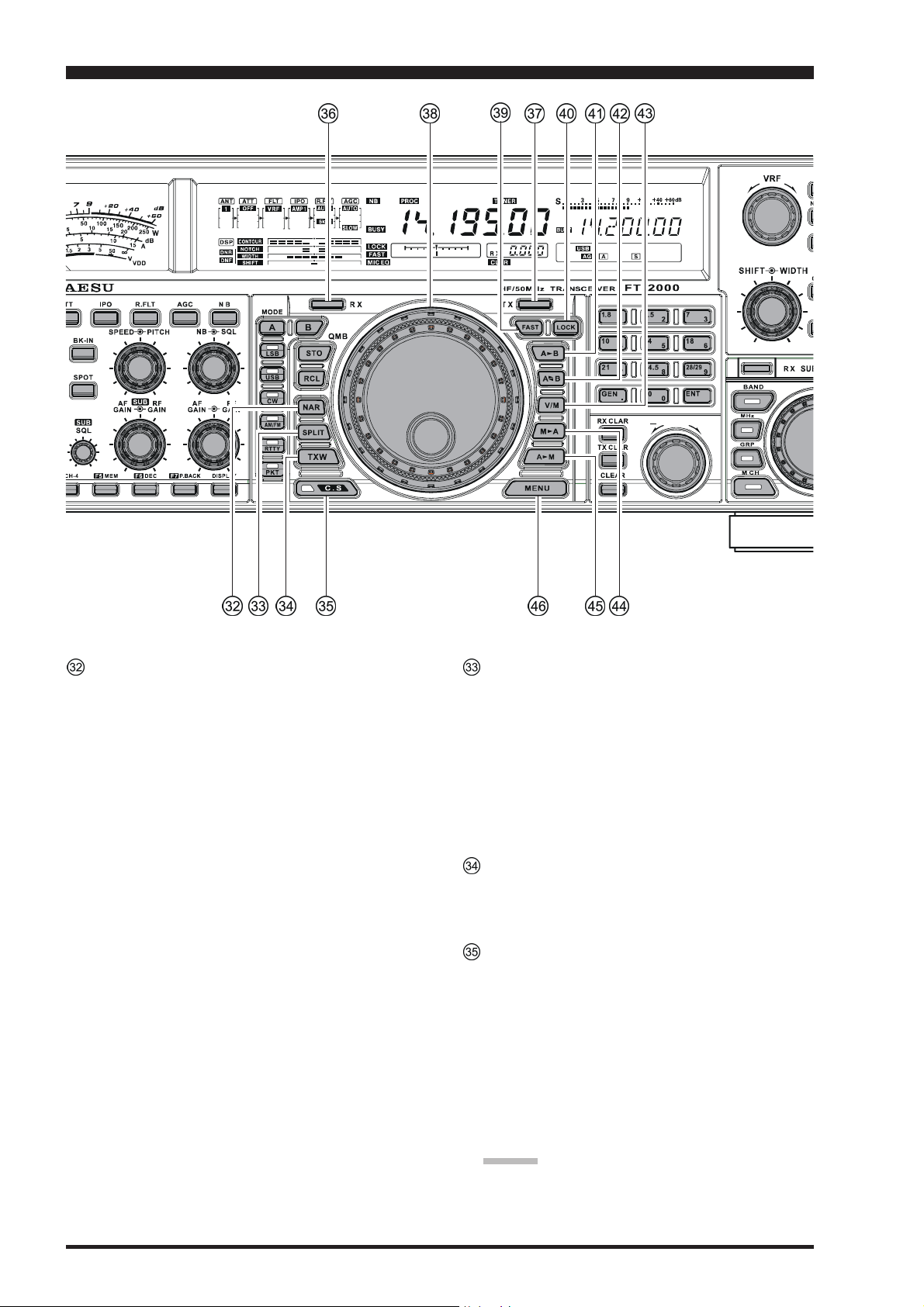
Main Tuning Dial Knob
This large knob adjusts the operating frequency of the
Main band (VFO-A) or a recalled memory. Clockwise
rotation of this knob increases the frequency. Default
tuning increments are 10 Hz (100 Hz in AM and FM
modes); when the [FAST] button is pressed, the tuning steps increase. The available steps are:
OPERATING MODE
LSB/USB/CW/RTTY/PKT(SSB
AM/FM/PKT(FM
Numbers in parentheses indicate steps when the [FAST] button is On.
ADVICE
The tuning steps for the Main Tuning Dial knob are
set, at the factory, to 10 Hz per step. Via Menu item
“118 tun DIALSTP,” however, you may change this
setting from 10 Hz to 5 Hz or 1 Hz instead. When press
the [FAST] button, the tuning step change to 100 Hz.
)
::
:
::
1 STEP
)
10 Hz (100 Hz
100 Hz (1 kHz
1 DIAL ROTATION
)
10 kHz (100 kHz
)
100 kHz (1 MHz
)
)
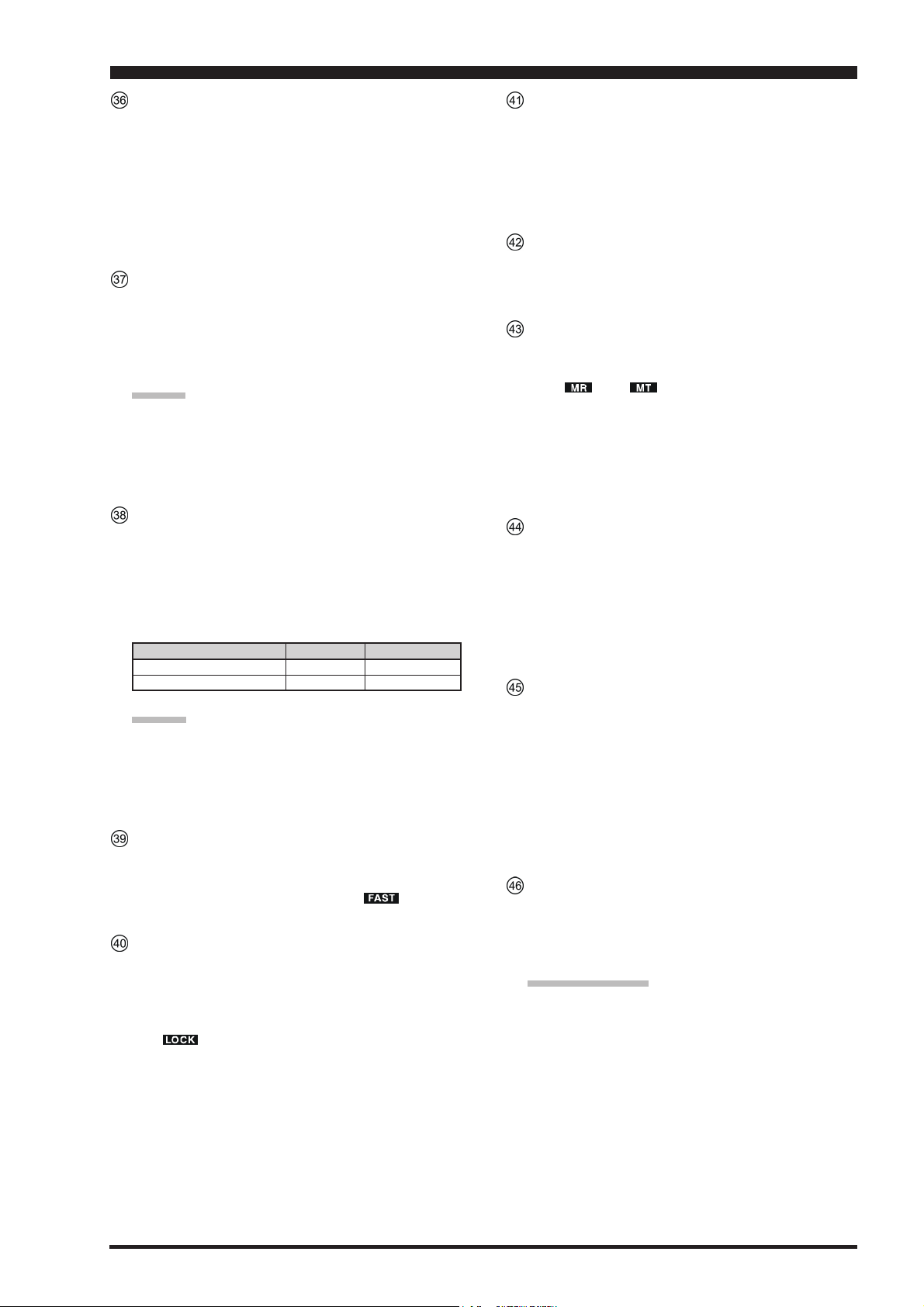
FAST Switch
Pressing this button will change the tuning step to 100
Hz.
When this function is activated, the “ ” icon appears in the display.
LOCK Switch
This button toggles locking of the Main Tuning Dial
knob, to prevent accidental frequency changes. When
the button is active, the Main Tuning Dial knob can
still be turned, but the frequency will not change, and
the “ ” icon appears in the display.
[
AXB] Switch
Press this button momentarily to transfer data from the
Main band (VFO-A) frequency (or a recalled memory
channel) to the Sub band (VFO-B), overwriting any
previous contents in the Sub band (VFO-B). Use this
key to set both Main band (VFO-A) and Sub band
(VFO-B) receivers to the same frequency and mode.
X
[
A
W
B] Switch
Pressing this button momentarily exchanges the contents of the Main band (VFO-A) (or a recalled memory
channel) and the Sub band (VFO-B).
[
V/M] Switch
This button toggles Main band (VFO-A) receiver operation between the memory system and the VFO. Either “ ” or “ ” will be displayed to the under
the main frequency display field to indicate the current selection. If you have tuned off of a Memory channel frequency (MT), pressing this button returns the
display to the original memory contents (MR), and
pressing it once more returns operation to the Main
VFO (no icon).
[
MXA] Switch
Pressing this button momentarily displays the contents
of the currently-selected memory channel for three seconds.
Holding this button in for 2 seconds copies the data
from the currently-selected memory to the Main VFO
(VFO-A), as two beeps sound. Previous data in the
Main VFO will be overwritten.
[
AXM] Switch
Pressing and holding in this key for 1/2 second (until
the double beep) copies the current operating data from
the Main band (VFO-A) into the currently selected
memory channel, overwriting any previous data stored
there. See page 100 for details.
Also, pressing and holding in this button after recalling a memory, without first retuning, causes the memory
channel to be “masked,” and repeating the process restores the masked memory.
MENU Switch
This button is used for gaining access to the Menu system, for configuring various transceiver characteristics. Menu operation is described in detail, in this
manual, beginning on page 112.
IMPORTANT NOTE:
Pressing this button momentarily activates the Menu,
and the Menu items will appear on the display; once
you are finished, you must press and hold in the
[
MENU] button for two seconds to save any configu-
ration changes (momentarily pressing the [MENU
button to exit will not save the changes).
]
Page 23FT-2000D OPERATING MANUAL
Page 26
FRONT PANEL CONTROLS & SWITCHES
CLAR
+
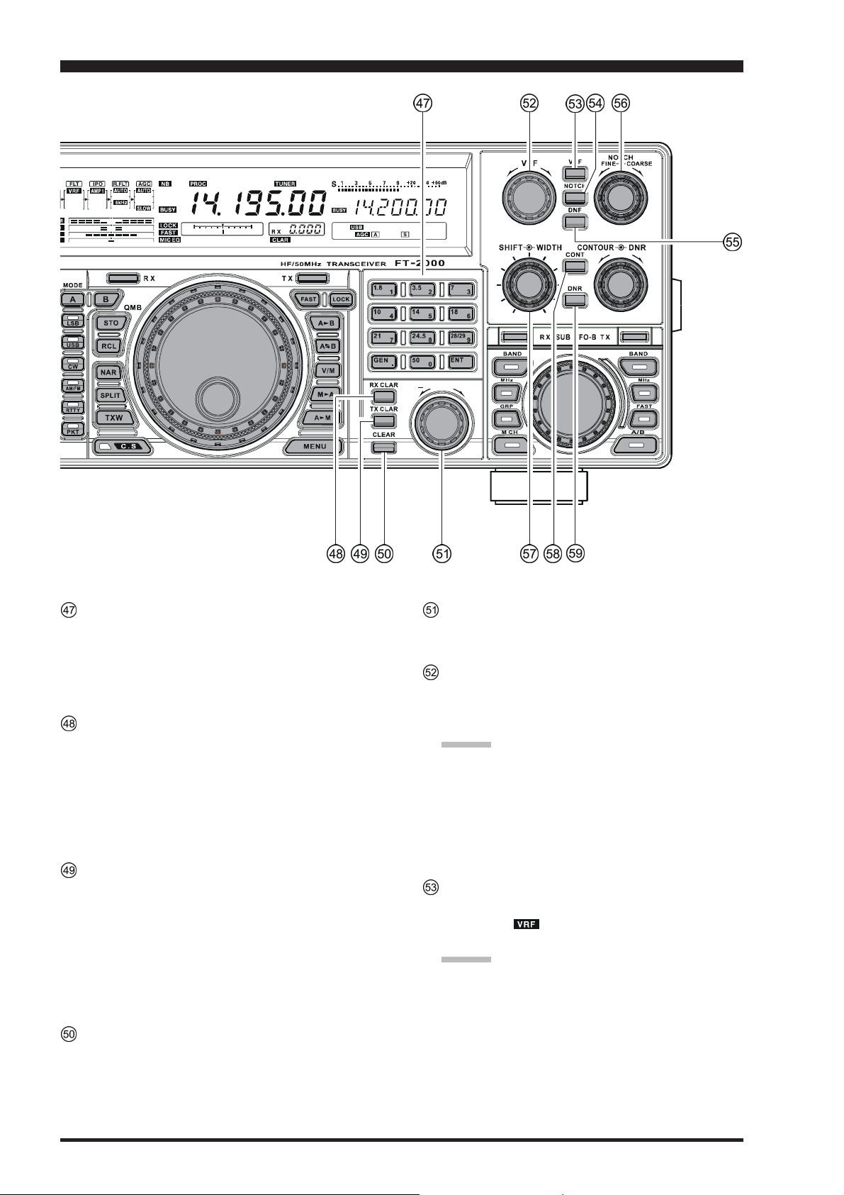
BAND Keys
These keys allow one-touch selection of the desired
Amateur band (1.8 ~ 50 MHz).
What’s more, these keys may be used for direct entry
of a desired operating frequency during VFO operation.
RX CLAR Switch
Pressing this button activates the RX Clarifier, to allow offsetting the Main (VFO-A) receiving frequency
temporarily. Press this button once more to return the
Main receiver to the frequency shown on the main frequency display field; the Clarifier offset will still be
present, though, in case you want to use it again. To
cancel the Clarifier offset, press the [CLEAR] button.
TX CLAR Switch
Pressing this button activates the TX Clarifier, to allow offsetting the Main (VFO-A) transmit frequency
temporarily.
Press this button once more to return the transmitter to
the Main (VFO-A) frequency shown on the main frequency display field; the Clarifier offset will still be
present, though, in case you want to use it again. To
cancel the Clarifier offset, press the [CLEAR] button.
CLEAR Switch
Pressing this button clears out any frequency offset you
have programmed into the Clarifier register (thereby
setting the offset to “Zero”).
CLAR Knob
This knob tunes the Clarifier offset frequency up to
9.999 kHz.
VRF Knob
This knob tunes the passband of the VRF (Variable RF
Filter) preselector circuit for maximum receiver sensitivity (and out-of-band interference rejection).
ADVICE:
The relative position of the VRF passband can be
observed on the Tuning Offset Indicator of the display whenever the [VRF] knob is turned.
When the optional RF μTuning Kit is connected,
this knob allows adjustment of the center frequency
of the μ-Tuning filter passband (which is much
narrower than that of the VRF).
VRF Switch
This button turns the VRF filter on and off. While activated, the “ ” icon will appear in the FLT column
of the Receiver Configuration Indicator on the display.
ADVICE:
When the optional RF μTuning Kit is connected, pressing this button will engage the μ-Tuning filter. The
μTuning Kit provides much better RF selectivity than
any other RF filter in the Amateur industry, yielding
outstanding protection from high RF levels not far removed from the current operating frequency.
Page 24 FT-2000D OPERATING MANUAL
Page 27

FRONT PANEL CONTROLS & SWITCHES
NOTCH Switch
This button turns the Main band (VFO-A) receiver’s
IF Notch Filter on and off.
When the IF Notch Filter is activated, the peak position of the IF Notch Filter is depicted graphically in
the display. The IF Notch Filter center frequency is
adjusted via the [NOTCH] knob.
DNF Switch
This button turns the Main band (VFO-A) receiver’s
Digital Notch Filter on and off. When the Digital Notch
Filter is activated, the “ ” icon appears in the display. This is an automatic circuit, and there is no adjustment knob for the DNF.
NOTCH Knob
This knob adjusts the center frequency of the Main
band (VFO-A) receiver’s IF Notch Filter. The Notch
Filter is engaged via the [NOTCH] button.
Initially, the approximate center frequency of the IF
Notch Filter is adjusted by the outer [COARSE] knob;
then, fine tuning of the center frequency is adjusted by
the inner [FINE] knob.
AA
DD
VICEVICE
A
D
VICE
DD
VICEVICE
AA
The Sub band (VFO-B) frequency display will show
the Notch frequency for 3 seconds whenever the
[
NOTCH] knob is turned.
You may disable this feature (displaying the Notch frequency) via Menu item “015 diSP LVL IND.” See page
117 for details.
SHIFT WIDTH Knobs
SHIFT Knob
The inner [SHIFT] knob provides adjustment of the
IF DSP passband, using 20 Hz steps for precise adjustment and easy reduction of interference on either
side of your operating frequency. The total adjustment
range is ±1 kHz. The normal operating setting for this
knob is straight up, in the 12 o’clock position.
ADVICE:
The Sub band (VFO-B) frequency display will show
the shift value of the IF SHIFT for 3 seconds whenever the [SHIFT] knob is turned.
You may disable this feature (displaying the shift
value of the IF SHIFT) via Menu item “015 diSP
LVL IND.” See page 117 for details.
You may shift the Sub band (VFO-B) filter pass-
band via Menu item “044 S-iF LSB SFT” through
“051 S-iF PKT-USB.”
(
EXCEPT ON FM MODE
WIDTH Knob
The outer [WIDTH] knob sets the overall bandwidth
of the IF DSP filter for the Main (VFO-A) receiver.
The center (12 o’clock) position establishes the “default” bandwidth (for example, 2.4 kHz for SSB);
clockwise rotation of this knob increases the bandwidth
(out to a maximum of 4 kHz), while counter-clockwise rotation reduces the bandwidth.
When the NAR (Narrow) filter selection is engaged,
the [WIDTH] knob is disabled.
The [SHIFT] knob may be used to re-center the passband response on the incoming signal, and you may
find that the CONTOUR and IF Notch Filter may also
help improve intelligibility and/or reduce interference.
See also the discussions of the [CONTOUR] knob and
[
NOTCH] knob.
ADVICE:
The Sub band (VFO-B) frequency display will show
the width of the IF passband for 3 seconds whenever the [WIDTH] knob is turned.
You may disable this feature (displaying the width
of the IF passband) via Menu item “015 diSP LVL
IND.” See page 117 for details.
When the [NAR] button has been pushed, the
[
WIDTH] knob no longer functions (except the CW
mode). The IF SHIFT system is still fully operational, however.
CONT Switch
This button turns the Main band (VFO-A) receiver’s
)
CONTOUR filter on and off. When the CONTOUR
Filter is activated, the peak position of the CONTOUR
Filter is depicted graphically in the display. Adjustment
of the CONTOUR filter’s center frequency is provided
by the [CONTOUR] knob.
Furthermore, in the CW mode, press and hold this button for 2 seconds to activate the APF (Audio Peak Filter) which provides a very narrow audio bandwidth;
the peak position of the APF is depicted graphically in
the display. The APF circuit is an automatic circuit,
and there is no adjustment knob for the APF.
::
NOTE
:
::
There are times, when you’re trying to remove interference with a sharp DSP filter, that the remaining signal has a somewhat unnatural sound. This is caused by
the cutting of some frequency components, leaving
other components in excess. The CONTOUR filter allows you (especially) to roll off certain frequency components inside the remaining passband, but in a smooth
manner that helps restore a natural sound and/or raise
intelligibility.
DNR Switch
This button turns the Main band (VFO-A) receiver’s
Digital Noise Reduction circuit on and off. When the
Digital Noise Reduction is activated, the “ ” icon
appears in the display. Adjustment of the Noise Reduction level is provided by the [DNR] knob.
Page 25FT-2000D OPERATING MANUAL
Page 28

FRONT PANEL CONTROLS & SWITCHES
CLAR
+
CONTOUR DNR Knob
CONTOUR Knob
The inner [CONTOUR] knob selects the desired Main
band (VFO-A) receiver’s CONTOUR filter response.
The CONTOUR filter is engaged via the [CONTOUR
button.
ADVICE:
The Sub band (VFO-B) frequency display will show
the CONTOUR frequency for 3 seconds whenever the
inner [CONTOUR] knob is turned.
You may disable this feature (displaying the CONTOUR frequency) via Menu item “015 diSP LVL
IND.” See page 117 for details.
DNR Knob
The outer [DNR] knob is used to select one of the 15
available noise reduction parameters for the Main band
(VFO-A) receiver’s Digital Noise Reduction system.
ADVICE:
The Sub band (VFO-B) frequency display will show
the current noise reduction parameter for 3 seconds
whenever the outer [DNR] knob is turned.
You may disable this feature (displaying the current
noise reduction parameter) via Menu item “015 diSP
LVL IND.” See page 117 for details.
RX Indicator/Switch
This is the button that turns the Sub (VFO-B) receiver
On and Off. When this button is pressed to make the
Sub (VFO-B) receiver active, the Green LED imbed-
]
ded within the button will light up. Pressing the button
again will disable this receiver, and the imbedded Green
LED will turn off.
TX Indicator/Switch
This is the button that turns the Sub (VFO-B) transmitter On and Off. When this button is pressed to transfer transmitter control to the Sub (VFO-B) frequency
and mode, the Red LED imbedded within the button
will light up. Pressing this button once more will transfer frequency/mode control back to the Main (VFOA) side, and the Red LED imbedded within this button
will turn off.
SUB VFO-B Knob
Depending on the status of the [A/B] button located at
the right bottom of the [SUB VFO-B] knob, the [SUB
VFO-B] knob is used for functions associated with the
Main (VFO-A) or Sub (VFO-B) frequency control registers.
Page 26 FT-2000D OPERATING MANUAL
Page 29

FRONT PANEL CONTROLS & SWITCHES
(
VFO-A) BAND Switch
Pressing this button allows you to select the Main
(VFO-A) operating band (Amateur bands) using the
[
SUB VFO-B] knob.
(
VFO-A) MHz Switch
Pressing this button allows you to tune the Main band
(VFO-A) frequency down or up in 1 MHz increments,
using the [SUB VFO-B] knob.
GRP Switch
Pressing this button allows you to select the memory
group using the [SUB VFO-B] knob.
M CH Switch
Pressing this button allows you to select the memory
channel using the [SUB VFO-B] knob.
(
VFO-B) BAND Switch
When the [A/B] button is pressed, and the Orange lamp
to the right of the [SUB VFO-B] knob lights up, pressing this button allows you to select the Sub (VFO-B)
operating band (Amateur bands) using the [SUB VFO-
B] knob.
(
VFO-B) MHz Switch
When the [A/B] button is pressed, and the Orange lamp
to the right of the [SUB VFO-B] knob lights up, pressing this button allows you to tune the Sub band (VFOB) frequency down or up in 1 MHz increments, using
the [SUB VFO-B] knob.
FAST Switch
When the [A/B] button is pushed, and the Orange lamp
to the right of the [SUB VFO-B] knob lights up, the
[
SUB VFO-B] knob will be controlling the Sub band
(VFO-B) frequency; pressing the [FAST] button will
change the tuning step to 100 Hz.
A/B Switch
The [A/B] button determines whether the actions of
the [SUB VFO-B] knob will be applied to the Main
band (VFO-A) or the Sub band (VFO-B).
Pressing this button once causes the Orange lamp to
the right of the [SUB VFO-B] knob to light up; in this
case, rotation of the [SUB VFO-B] knob affects operation on the Sub band (VFO-B). Pressing the [A/B
button once more causes the Orange lamp to turn off;
in this instance, rotation of the [SUB VFO-B] knob
affects operations associated with the Main band (VFOA).
]
Page 27FT-2000D OPERATING MANUAL
Page 30
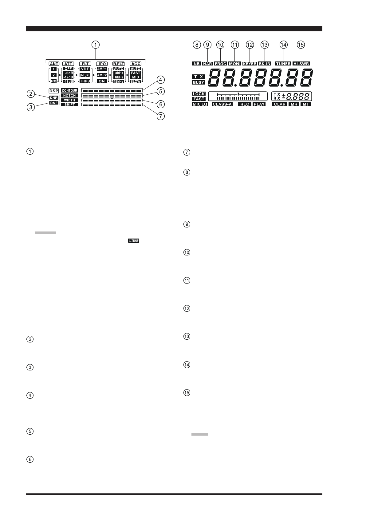
DISPLAY INDICATIONS
(
LEFT SIDE & CENTER
)
Receiver Configuration Indicators
ANT (1, 2, RX):
Indicates the antenna selected for operation by the front
panel [1/2] and [RX] antenna switches.
ATT (OFF, –6 dB, –12 dB, –18 dB):
Indicates the attenuation level selected for operation
by the front panel [ATT] button.
FLT (VRF, μ-TUNE, THRU):
Indicates the RF filter selected for operation by the
front panel [VRF] button.
ADVICE:
The μ-TUNE filter is an option. The “ ” icon will
not appear when the optional μ-TUNE unit is not connected.
IPO (AMP 1, AMP 2, ON):
Indicates the front end RF amplifier selected for operation by the front panel [IPO] button.
R.FLT
Indicates the 1st IF Roofing Filter selected: AUTO
(mode-determined), 3 kHz, 6 kHz, or 15 kHz.
AGC (AUTO, FAST, MID, SLOW):
Indicates the AGC decay time selected for Main band
(VFO-A) operation by the front panel [AGC] switch.
DNR
This indicator appears whenever the Digital Noise Reduction feature is activated.
DNF
This indicator appears whenever the Digital Notch Filter is activated.
CONTOUR
The peak position of the CONTOUR Filter is depicted
graphically here when the CONTOUR Filter is activated.
NOTCH
The null position of the IF Notch Filter is depicted
graphically here when the IF Notch Filter is activated.
WIDTH
Indicates the bandwidth of the DSP IF filter.
SHIFT
Indicates the peak position of the DSP IF filter.
NB
This indicator appears when the Main band (VFO-A)
receiver’s (short duration) Noise Blanker is activated.
This indicator will blink for three seconds, and thereafter appears continuously, when the Main band (VFOA) receiver’s longer-pulse Noise Blanker is activated.
NAR
This indicator appears whenever the Main band (VFOA) receiver’s narrow IF DSP filter is engaged.
PROC
This indicator appears whenever the DSP Speech Processor is activated.
MONI
This indicator appears whenever the transmit monitor
circuit is activated.
KEYER
This indicator appears whenever the internal CW keyer
is activated.
BK-IN
This indicator appears whenever CW break-in operation is activated.
TUNER
This indicator appears when the internal Automatic Antenna Tuner is activated.
HI SWR
This indicator appears if the directional coupler and
microprocessor detect an abnormally high SWR condition (over 3.0:1) that cannot be resolved by the Automatic Antenna Tuner.
NOTE:
If this indicator appears, check to be sure that you have
the correct antenna selected on the current operating
band. If so, you will need to check the condition of the
antenna, its coaxial cable, and/or the connectors on the
cable so as to locate and correct the fault.
Page 28 FT-2000D OPERATING MANUAL
Page 31

DISPLAY INDICATIONS
(
CENTER
)
TX
This indicator appears during transmission on the Main
band (VFO-A) frequency.
BUSY
This indicator appears whenever the Main band (VFOA) receiver squelch is open. If this indicator is not showing, and reception seems to have been lost on the Main
receiver for no apparent reason, check the position of
the SQL knob and rotate it fully counter-clockwise to
restore reception.
Main (VFO-A) Frequency Display
This is the Main band (VFO-A) frequency display.
ADVICE:
When setting the Menu items, the Menu item num-
ber and Menu group name will appear in this area
during setup.
When setting the CTCSS frequency for Encoding
or Tone Squelch operation, the current tone information will appear in this area during setup.
LOCK
This indicator appears when the Main Tuning Dial knob
is locked.
FAST
This indicator appears when the Main Tuning Dial
knob’s tuning rate is selected to fast.
MIC EQ
This indicator appears whenever the Three-Band Parametric Microphone Equalizer is activated.
CLASS-A
This indicator appears when Class-A operation is engaged.
Tuning Offset Indicator
This is a tuning scale that, as configured from the factory, provides a visual CW tuning indication of the incoming signal’s offset from your transceiver’s CW carrier frequency, as programmed by the relative clarifier
offset, or the peak position of the VRF/μ-TUNE filter.
REC
This indicator appears while the voice recorder is recording the receiver audio, and/or the memory is recording your CW or voice message.
PLAY
This indicator appears while the voice recorder is playing back the recorded audio, and/or the memory is playing back the recorded CW or voice message.
Multi-Display Window
This window displays either the Clarifier offset or
Memory Channel Number.
ADVICE:
During FM operation, the Repeater Shift will be
indicated in this window. A Negative frequency shift
will be indicated by “–” while a Positive frequency
shift will be indicated by “+.”
When setting the Menu items, the current setting
will appear in this area.
When setting the CTCSS frequency for Encoding
or Tone Squelch operation, the current repeater shift
direction will appear in this area.
CLAR
This indicator appears whenever the Clarifier function
is activated.
MR
This indicator appears when the FT-2000D is in the
Memory Recall mode.
MT
This indicator appears when the FT-2000D is in the
Memory Tune mode to indicate that the memory contents have been temporarily changed.
Page 29FT-2000D OPERATING MANUAL
Page 32

DISPLAY INDICATIONS
(
RIGHT SIDE
)
Sub (VFO-B) Receiver S-Meter
Displays the strength of signals received on the Sub
band (VFO-B).
TX
This indicator appears during transmission on the Sub
band (VFO-B) frequency.
BUSY
This indicator appears whenever the Sub band (VFOB) receiver squelch is open. If this indicator is not showing, and reception seems to have been lost on the Sub
receiver for no apparent reason, check the position of
the Sub [SQL] knob and rotate it fully counter-clockwise to restore reception.
Sub (VFO-B) Frequency Display
This is the Sub band (VFO-B) frequency display.
ADVICE:
When activating the CW Spot Tone, the current tone
frequency will appear in this area.
When turning the [PITCH], [SPEED], [CON-
TOUR], [NOTCH], [DNR], [DELAY], [RF
PWR], [MIC], [PROC], [SHIFT], or [WIDTH
knob, each frequency or value will appear in this
area for 3 seconds.
If the knob is turned too slowly, the frequency display may not show the value. This is to prevent
undesired display of the functions caused by noise
or slight vibration of the controls; however, the
actual value will be changed even if not displayed.
You can observe the fine adjustment for a few seconds while the display is active.
While adjusting functions, the display may occasionally skip one of the numbers in the sequence;
this is due to “rounding” of the encoder steps in
the ADC converter. Set the values to your preference, they are unique to your radio and may not
directly correspond to other units.
When setting the Menu items, the Menu item name
will appear in this area during setup.
When setting the CTCSS frequency for Encoding
or Tone Squelch operation, the current tone frequency will appear in this area during setup.
LSB, USB, CW, AM, FM, RTTY, PKT
Displays the currently selected operating mode for the
Sub (VFO-B) receiver.
FAST
This indicator appears when the [SUB VFO-B] knob’s
tuning rate is selected to fast.
AGC A, F, M, S
Displays the currently selected AGC decay time for
the Sub (VFO-B) receiver.
A: Auto, F: Fast, M: Medium, S: Slow
NB
This indicator appears when the Sub (VFO-B)
receiver’s (short duration) Noise Blanker is activated.
This indicator will blink for three seconds, and thereafter appears continuously, when the Sub (VFO-B)
receiver’s longer-pulse Noise Blanker is activated.
NAR
This indicator appears whenever the optional Sub
(VFO-B) receiver’s narrow filter is selected.
]
Page 30 FT-2000D OPERATING MANUAL
Page 33

REAR PANEL
RX ANT OUT Jack
This BNC jack provides output of the receiver signal
lines from the Antenna jacks which are connected to
“RX” side of the transceiver’s main T/R switching circuitry.
RX ANT IN Jack
This type-M jack is for a separate receive-only antenna.
An antenna connected here can be used when the [RX
antenna button on the front panel is pressed.
If you want to use some special kind of external
bandpass filter or preamplifier, you may connect it
between the RX ANT OUT and RX ANT IN jacks.
ANT 1/2 Jacks
Connect your main antenna(s) here, using a type-M
(PL-259) plug and coaxial feedline for each. These antenna ports are always used for transmission, and also
are used for reception unless a separate receive antenna is also used for the receiver. The internal antenna
tuner affects only the antenna(s) connected here, and
only during transmission.
Warning!
The 141V RF voltage (@200 W/50 Ω) is applied to
the TX RF section of the transciver while transmitting.
Do not touch the TX RF section absolutely while transmitting.
ANT “1”
ANT “2”
ANTENNA (1/2) SWITCH
TX/RX RELAY
ANTENNA (RX) SWITCH
Transmitter Section
Receiver Section
COOLING FAN
This is a cooling fan for cooling down the Power Amplifier Unit.
Usually, this cooling fan does not rotate. However,
when the temperature begins to rise, the cooling fan
begins to rotate.
DC 13.8 V ...– IN Jack
]
Connect this 6-pin connector to the DC 13.8 V Output
Jack on the FP-2000 AC Power Supply, using the supplied DC Power Cord. This connector provides +13.8
V DC supply voltage for the FT-2000D.
DC 50 V ...– IN Jack
Connect this 2-pin connector to the DC 50 V Output
Jack on the FP-2000 AC Power Supply, using the supplied DC Power Cord. This connector provides +50 V
DC supply voltage for the power amplifier of the FT-
2000D.
GND
Use this terminal to connect the transceiver to a good
earth ground, for safety and optimum performance. Use
a large diameter, short braided cable for making ground
connections, and please refer to page 9 for other notes
about proper grounding.
μ-TUNE Jacks
These jacks are used for signal input/output of the optional RF μTuning Kit.
RX ANT “OUT”
RX ANT “IN”
Page 31FT-2000D OPERATING MANUAL
Page 34

REAR PANEL
ROT (ROTATOR) Jack
This 6-pin MINI-DIN Jack accepts a cable connected
to a YAESU G-800DXA/-1000DXA/-2800DXA Antenna Rotator (listed models are current as of early
2009). You may control the antenna azimuth rotation
(and rotation speed) using the Function buttons on the
front panel.
BND (BAND) DATA Jack
This 8-pin output jack provides band selection data
which may be used for control of optional accessories
such as the VL-1000 Solid-state Linear Amplifier.
PACKET Jack
This 5-pin input/output jack provides receiver audio
and squelch signals, and accepts transmit (AFSK) audio and PTT control, from an external Packet TNC.
Pinout is shown on page 15. The receiver audio level
at this jack is approximately 100 mVp-p (@600 Ohms).
RTTY Jack
This 4-pin input/output jack provides connections for
an RTTY terminal unit. Pinout is shown on page 15.
The receiver audio level at this jack is at a constant
100-mV (@600 Ohms) level. FSK keying at this jack
is accomplished by a closure of the SHIFT line to
ground by the terminal unit.
PTT Jack
This RCA input jack may be used to provide manual
transmitter activation using a footswitch or other
switching device. Its function is identical to the [MOX
button on the front panel. The same line is available at
the PACKET and RTTY jacks for TNC control. Open-
circuit voltage is +13.5 VDC, and closed-circuit current is 5 mA.
MIC (PATCH) Jack
This RCA input jack accepts transmitter audio - either
AFSK or voice - for transmission. This line is mixed
with the microphone audio input line, so the microphone should be disconnected if using this jack and
mixing is not desired. The optimum impedance is 500
~ 600 Ohms, and the nominal input level should be 5
mV.
TRV Jack
This RCA jack provides a low level RF output for use
with a transverter. Maximum output is approximately
–10 dBm (0.1 mW) at 50 Ohms.
REC Jack
This RCA jack provides low-level receiver audio output and transmit (monitor) audio (requires the [MONI
button is turned on), for recording or external amplification. Peak signal level is 30 mVp-p at 10 kOhms.
]
]
Page 32 FT-2000D OPERATING MANUAL
Page 35

REAR PANEL
EXT ALC Jack
This RCA input jack accepts negative-going external
ALC (Automatic Level Control) voltage from a linear
amplifier, to prevent over-excitation by the transceiver.
Acceptable input voltage range is 0 to –4 VDC.
TX REQ Jack
When this RCA jack shorted to ground, it puts the FT2000D into the transmit mode, and sends out a steady
CW carrier, for linear amplifier or manual antenna tuner
adjustment.
TX GND Jack
This RCA jack’s center pin is closed to ground while
the transceiver’s transmitter is engaged. It may be used
for control of a peripheral device, most typically a linear amplifier. To enable this jack, please set Menu item
“146 tGEn ETX-GND” to the “
tion.
The relay circuit of the FT-2000D used for this jack is
capable of switching AC voltage of 100 Volts at up to
300 mA, or DC voltages or 60 V at 200 mA or 30 V at
up to 1 Amp.
EnAEnA
EnA” (Enable) selec-
EnAEnA
+13.8 V Jack
This RCA output jack provides regulated, separately
fused 13.8 VDC at up to 200 mA, to power an external
device such as a packet TNC. Make sure your device
does not require more current (if it does, use a separate
power source).
AF OUT
This gold-plated 3-contact jack provides dual-channel
low-level receiver output, for recording or external amplification. Peak signal level is 300 mVp-p at 10 kOhms. Main band (VFO-A) receiver audio is on the
left channel (tip), and sub band (VFO-B) receiver audio is on the right channel (ring). A stereo amplifier or
recorder is recommended, to record each receiver’s
audio separately when dual reception is enabled (audio from either receiver, or both, may be used via this
jack). The front panel [AF GAIN] knobs do not affect
the signals at this jack.
REM (REMOTE) Jack
By plugging in the optional FH-2 Remote Control Keypad to this gold-plated jack, direct access to the FT-
2000D CPU is provided for control functions such as
contest memory keying, plus frequency and function
control.
EXT SPKR
This gold-plated two-contact output jack provides receiving audio from the Main (VFO-A) and Sub (VFOB) receivers for an external loudspeaker or speakers,
such as the SP-2000. Inserting a plug into this jack
disables the internal loudspeaker. Impedance is 4 ~ 8
Ohms.
μ-TUNE Jack
This 10-pin MINI-DIN jack used for control of the
optional RF μTuning Kit.
DMU Jack
This 8-pin MINI-DIN jack accepts a cable connected
to an optional DMU-2000 Data Management Unit.
PGM (PROGRAM) Jack
This coverd 9-pin MINI-DIN jack is used at the factory. Please do not connect any equipment to this jack.
CAT Jack
This 9-pin serial DB-9 jack allows external computer
control of the FT-2000D. Connect a serial cable here
and to the RS-232C COM port on your personal computer (no external interface is required).
KEY Jack
This 1/4-inch phone jack accepts a CW key or keyer
paddle. A 2-contact plug cannot be used in this jack.
Key-up voltage is +5 V, and key-down current is 1 mA.
Plug wiring is shown on page 15, and this jack may be
configured for keyer, “Bug,” “straight key,” or computer keying interface operation via Menu item “056
A1A R-TYPE.”
Page 33FT-2000D OPERATING MANUAL
Page 36

FP-2000 SWITCHES & JACKS
POWER Switch
This is the FP-2000’s main ON (I)/OFF (O) switch.
When turned on, the FP-2000 LED indicator will glow
red several seconds later.
If this main switch is not set to the “(I)” position, the
FT-2000D’s [POWER] switch will not function.
AC IN Jack
Connect the supplied 3-wire AC line cord to this socket.
Cooling Fan
This is a fan for cooling the internal power supply unit.
Usually, this fan does not rotate. However, when the
temperature begins to rise, the cooling fan begins to
rotate.
NOTE
Rarely, when a rush of current flows, the FP-2000
may buzz faintly. This is a normal condition.
OUTPUT DC 13.8 V Jack
Connect this 6-pin connector to the DC 13.8 V Input
Jack on the FT-2000D, using the supplied DC Power
Cord. The DC output is 13.8 Volts, with maximum
current of 6 Amps.
OUTPUT DC 50 V Jack
Connect this 2-pin connector to the DC 50 V Input
Jack on the FT-2000D, using the supplied DC Power
Cord. The DC output is 50 Volts, with maximum current of 12 Amps.
FUSE
This holder requires a 15 Amp fuse. Always use the 15
Amp fuse, whether operating on 100 - 120 VAC or
200 - 240 VAC.
Page 34 FT-2000D OPERATING MANUAL
Page 37

BASIC OPERATION:RECEIVING ON AMATEUR BANDS
Before turning on main power, please verify the following items once more.
Have you made all ground connections securely? See page 9 for details.
Do you have your antenna(s) connected to the rear-panel Antenna jack(s)? See page 10 for details.
Is your microphone (and/or key or paddle) connected? See pages 11 and 12 for details.
If using a linear amplifier, have all interconnections been successfully completed? See pages 13 and 14 for details.
Please rotate both [AF GAIN] controls to their fully counter-clockwise positions, to avoid a loud blast of audio when
the transceiver turns on. See page 21 for details.
Rotate the [RF PWR] control fully counter-clockwise, to set minimum power at first. See page 20 for details.
If your AC mains power should suffer a significant fluctuation or interruption, we recommend that you go through a
complete power-up cycle, in order to ensure that all circuits are properly initialized. To do this, be sure the FT-2000D’s
[
POWER] switch is turned off, then set the FP-2000’s [POWER] switch to the “O” position. Now unplug the AC
cable from the rear panel of the FP-2000, and wait ten seconds before proceeding with the start-up procedure described
on next page.
Page 35FT-2000D OPERATING MANUAL
Page 38

BASIC OPERATION:RECEIVING ON AMATEUR BANDS
Here is the typical start-up procedure for normal operation:
(
VFO-B) [BAND] Button
[
POWER] Switch
[
ANTENNA] Button
[
SQL] Knob
[
MODE] Button
Main [RX] Button
[
FAST] Button
(
VFO-B) [MHz] Button
Sub [RX] Button
CLAR
+
Sub [SQL] Knob
Sub [AF GAIN] Knob
1. Set the FP-2000’s [POWER
[
AF GAIN] Knob
]
switch to “I” position.
2. Press and hold in the FT-2000D’s
[
POWER] switch for one second
to turn the transceiver on.
3. The transceiver will start up on 7.000.00
MHz LSB, and normal operation may begin.
NOTE:
To turn power off, press and hold in the FT-2000D’s
[
POWER] switch for one second.
4. Rotate the [AF GAIN] knob to set
a comfortable audio level on incoming signals or noise. Clockwise rotation of the [AF GAIN] knob increases the volume level.
NOTE:
When using headphones, start by rotating the [AF
GAIN] knob counter-clockwise, then bring the volume
level up after you put the headphones on. This will
minimize the chance of damage to your hearing caused
by an unexpectedly-high audio level.
5. Press the Main [RX] button to engage the Main
(VFO-A) receiver; the
imbedded LED will glow
Green.
ADVICE
::
:
::
If you press the Main
[RX]
button when the imbedded LED is already
glowing Green, the LED will now blink on and off;
this indicates that the Main (VFO-A) receiver is
temporarily muted. Just press the Main [RX] button once more to restore Main (VFO-A) receiver
operation.
Main Tuning Dial knob
Press the Sub [RX] button to
engage Dual Reception (using the Sub (VFO-B) receiver in addition to the
Main (VFO-A) receiver).
When you press the Sub
[RX]
will glow green; pressing this
button once more will turn off
the Sub (VFO-B) receiver, and
the imbeded LED will go dark.
Use the Sub receiver’s Sub [AF
GAIN] knob to adjust the Sub
(VFO-B) receiver volume level.
6. Press the [BAND] button corresponding to
the Amateur band on
which you wish to begin operation.
ADVICE
One-touch selec-
tion of each Amateur band between
1.8 and 50 MHz is provided.
The FT-2000D utilizes a triple band-stack VFO
selection technique, which permits you to store up
to three favorite frequencies and modes onto each
band’s VFO register. For example, you may store
one frequency each on 14 MHz CW, RTTY, and
USB, then recall these VFOs by successive, momentary presses of the [14] MHz band button. Each
Amateur band button may similarly have up to three
frequency/mode settings applied.
[
BAND] Button
(
VFO-A) [BAND] Button
(
VFO-A) [MHz] Button
button, its imbedded LED
::
:
::
[
A/B] Button
[
SUB VFO-B] Knob
Page 36 FT-2000D OPERATING MANUAL
Page 39

BASIC OPERATION:RECEIVING ON AMATEUR BANDS
If you press the (VFO-A) [BAND] button, the
[
SUB VFO-B] knob may be used as a band selec-
tion knob. If you press the (VFO-A) [MHz] button, rotation of the [SUB VFO-B] knob allows frequency navigation in 1 MHz steps. Depending on
the setting of the (VFO-A) [BAND], (VFO-A)
[
MHz], and [A/B] buttons, the function of the [SUB
VFO-B] knob will change.
7. Press the [ANTENNA 1/2] button to select the appropriate antenna for the band in use; alternatively, if one
is connected, you may also press the
[
ANTENNA RX] antenna selection
button. Two TX/RX antennas may be
connected, or one RX-only antenna.
ADVICE
Once you have made your antenna selection, that antenna is “remembered” by the microprocessor in conjunction with the VFO register (frequency and mode)
in use when you chose that particular antenna.
8. Press the appropriate [MODE] button to select the desired operating
mode.
ADVICE
By convention in the Amateur
When changing modes from SSB
::
:
::
::
:
::
bands, LSB is used on the 7 MHz
and lower bands (with the exception of 60 meters), while USB is
utilized on the 14 MHz and
higher bands.
to CW, you will observe a frequency shift on the display. This shift represents
the BFO offset between the “zero beat” frequency
and the audible CW pitch (tone) you can hear (the
pitch is programmed by the [PITCH] knob), even
though the actual tone that you hear is not changing. If you do not want this frequency shift to appear when changing modes from (for example) USB
to CW, use the Menu item “063 A1A FRQDISP,”
described on page 122.
When operating on the FM
mode, rotate the [SQL
(Squelch) knob clockwise just
to the point where the background noise is just silenced.
This is the point of maximum
sensitivity to weak signals. Excessive
advancement of the [SQL] knob will
degrade the ability of the receiver to
detect weak signals. Adjustment of the
Sub band (VFO-B) Squelch is accomplished using the Sub [SQL] knob.
9.
Rotate the Main Tuning Dial knob to tune around the
band, and begin normal operation.
ADVICE
Clockwise rotation of the Main Tuning Dial knob
It is possible to separate the frequency change over
If you want to navigate quickly, so as to effect rapid
OPERATING MODE 1 STEP 1 DIAL ROTATION
LSB, USB, CW, 10Hz 10kHz
RTTY, PKT(LSB
AM, FM, PKT(FM)100Hz [1kHz]100kHz [1MHz
[ ]
: [FAST] switch set to “ON”
::
:
::
increases the operating frequency, one “step” of the
synthesizer at a time; similarly, counter-clockwise
rotation of the Main Tuning Dial knob will decrease
the frequency.
Two steps, one “normal”
and one “fast,” are available
on each operating mode.
Pressing the [FAST] button
engages the “Fast” tuning
selection.
one dial rotation, only while operating solely on
the CW mode, using the Menu items “118 tun
DIALSTP,” and “119 tun CW FINE.” See page
127.
frequency change, there are several techniques
available:
y Direct keyboard entry of the frequency (see page
49).
y Use the [SUB VFO-B] knob to tune in 1 MHz
steps (see page 49).
y Use the microphone’s [UP]/[DWN] scanning
keys, if your microphone is so equipped (see
page 49).
MAIN TUNING DIAL KNOB TUNING RATE
)[
100Hz
]
][
100kHz
]
]
Page 37FT-2000D OPERATING MANUAL
Page 40

BASIC OPERATION:RECEIVING ON AMATEUR BANDS
OPERATION ON 60-METER (5 MHZ) BAND
The FT-2000D includes the capability for transmission and reception on the five spot frequencies assigned to the Ama-
teur Service in the United States. To operate on the 5 MHz band:
1. Press the [V/M] button once to enter the “Memory”
mode (a memory channel number “
on the Multi-Display Window in the display.
2. Press the [M CH] button. The LED imbedded in the
button will glow red to signify that rotation of the [SUB
VFO-B] knob will allow selection the memory chan-
nel.
ADVICE:
If the memory channel selection seems not to be operating, check see if the orange lamp to the right of the
[
SUB VFO-B] knob is illuminated. If so, pressing the
[
A/B] button will cause the orange lamp to the right of
the [SUB VFO-B] knob to go out. Now, press the [M
CH] button to begin memory channel selection.
3. Memory channels “
grammed, at the factory, with the permitted frequencies in the 5 MHz band, and the USB mode is automatically selected on these channels.
4. To exit from 60-meter operation and return to the VFO
mode, just press the [V/M] button.
US1US1
US1” through “
US1US1
USxUSx
USx” will appear
USxUSx
US5US5
US5” are pre-pro-
US5US5
(
U.S. VERSION ONLY
Main Tuning Dial Knob
)
[
V/M] Button
[
SUB VFO-B] Knob
[
M CH] Button
[
A/B] Button
NOTE:
The frequencies and operating mode for 5 MHz band operation are both fixed, and may not be changed.
Page 38 FT-2000D OPERATING MANUAL
Page 41

BASIC OPERATION:RECEIVING ON AMATEUR BANDS
CLAR (CLARIFIER) OPERATION ON MAIN (VFO-A
)
The [TX CLAR], [RX CLAR], [CLEAR] buttons and [SUB VFO-B] knob are used to offset either the receive, transmit,
or both frequencies from their settings on the Main band (VFO-A) frequency (the Clarifier does not affect the Sub band
(VFO-B), however). The four small numbers on the Multi-Display Window show the current Clarifier offset. The Clarifier
controls on the FT-2000D are designed to allow you to preset an offset (up to ±9.999 kHz) without actually retuning, and
then to activate it via the Clarifier’s [RX CLAR] and [TX CLAR] buttons. This feature is ideal for following a drifting
station, or for setting small frequency offsets sometimes utilized in DX “Split” work.
[
Here is the technique for utilizing the Clarifier:
CLAR] Knob
1. Press the [RX CLAR] button. In the Multi-Display
Window, the “
RXRX
RX” notation will
RXRX
appear, and the programmed offset will be applied to the receive
frequency.
2. Rotation of the [CLAR] knob will allow you to modify
your initial offset on the fly. Offsets of up to ±9.999
kHz may be set using the Clarifier.
To cancel Clarifier operation, press the [RX CLAR] button. The “
RXRX
RX” notation will disappear from the display.
RXRX
ADVICE:
[
RX CLAR] Button
[
TX CLAR] Button
[
CLEAR] Button
CLAR
+
Turning the Clarifier Off simply cancels the application of
the programmed offset from the receive and/or transmit
frequencies. To clear out the programmed Clarifier offset
altogether, and reset it to “zero,” press the [CLEAR] button. The programmed offset is displayed in the small multichannel window of the frequency display.
TX CLAR
Without changing the receive frequency, you may
alternatively apply the Clarifier offset to the transmit frequency (typically, for “split” DX pile-ups).
See page 79 for details.
The Tuning Offset Indicator provides a graphical representation of the Clarifier offset.
On CW, the Tuning Offset Indicator is used for CW Center Tuning, instead of Clarifier Offset, as the transceiver is
configured at the factory. If you wish to change this, so that the Clarifier Offset is also displayed on CW, use the
following procedure:
[
1. Press the [MENU] button to enter the Menu mode.
MENU] Button
2. Rotate the Main Tuning Dial knob to select Menu
item “010 diSP BAR SEL.”
3. Rotate the [SUB VFO-B] knob to select “
CLArCLAr
CLAr
CLArCLAr
(Clarifier)” (replacing the default “C-tn (CW TUNING)” selection).
4. Press and hold in
the [MENU] button for two seconds
[
Plus (+) Offset
]
Main Tuning Dial knob[SUB VFO-B] knob
to save the new setting and exit to nor-
[
Zero Offset
]
mal operation.
(
(–)
Offset
)
Minus
Page 39FT-2000D OPERATING MANUAL
Page 42

BASIC OPERATION:RECEIVING ON AMATEUR BANDS
LOCK
You may lock the setting of the Main Tuning Dial knob, to prevent accidental frequency change.
[
To lock out the Main Tuning Dial
knob, just press the [LOCK] button that is located to the right of the
Dial. To unlock the Dial setting, and
restore normal tuning, just press the
[
LOCK] button once more.
DIM
The illumination level of the analog meter and frequency display may be reduced, if you are using the transceiver in a dark
environment where high brightness is not desired.
[
To reduce the illumination level, press the
[
DIM] button, located
to the left of the analog
meter. To restore full
brightness, press the
[
DIM] button once
more.
DIM] Button
LOCK] Button
You may also customize the amount of brightness reduction engaged by the pressing of the [DIM] button, and may
use different brightness levels for different front panel areas. Menu item “008 diSP DIM MTR” adjusts the bright-
ness level of the analog meter; while menu item “009 diSP
DIM VFD” sets the brightness levels of the frequency display (these settings are effective only when the [DIM] button is pressed).
Page 40 FT-2000D OPERATING MANUAL
Page 43

NOTES
Page 41FT-2000D OPERATING MANUAL
Page 44

CONVENIENCE FEATURES
DUAL RECEIVE
The FT-2000D is capable of simultaneous reception on the same amateur band, using the Main (VFO-A) and Sub (VFOB) receivers, in what is called the Dual Receive mode. Especially useful for DX work, here is the operating procedure for
Dual Receive operation.
1. While receiving on the Main band (VFO-A), engage
the Sub (VFO-B) receiver by pressing the Sub [RX
button, located to the upper left of the [SUB VFO-B
knob. You will now be receiving on the two frequencies shown on the frequency display.
2. Adjusting the volume:
To adjust the Main (VFO-A) audio level, rotate the
Main [AF GAIN] knob. To adjust the Sub (VFO-B)
audio level, rotate the Sub [AF GAIN] knob. In both
cases, clockwise rotation of the knob will increase the
volume level.
3. Press the [B] button. Within five seconds of pressing
the [B] button, while the orange LED is blinking, you
may now change the operating mode for the Sub (VFOB) band by pressing the appropriate Mode selection
button.
4. Having pressed the [B] button in the previous step,
you may also press the [BAND] buttons to select the
operating band on which you want to set up the Sub
(VFO-B) receiver.
5. Rotate the Main Tuning Dial knob to adjust the Main
(VFO-A) frequency, and rotate the [SUB VFO-B
knob to adjust the Sub (VFO-B) frequency.
6. To cancel Dual Receive operation, and receive just on
the Main (VFO-A) receiver, press the Sub [RX] button; the imbedded green LED will go out, and
monoband operation on the Main (VFO-A) receiver
will resume.
::
NOTE
:
::
Please remember that, while the [B] mode button is blinking (for five seconds), any mode or band changes will still
be applied to the Sub band (VFO-B), whether or not Dual
Receive is engaged.
QUICK POINT:
By convention in the Amateur bands, LSB is used on the 7
MHz and lower bands (with the exception of 60 meters),
while USB is utilized on the 14 MHz and higher bands.
Sub [AF GAIN] Knob
[
]
SQL] Knob
Main Tuning Dial Knob
Sub [RX] Button
]
Sub [SQL] Knob
[
AF GAIN] Knob
[B]
Button
[
BAND] Button
[
SUB VFO-B] Knob
ADVICE:
When operating in Dual Receive, the manner in which
the audio is fed to the left and right sides of your headphones (Stereo, Monaural, or Mixed) may be configured using Menu item “091 rout HEADPHN” (see
page 124).
When changing modes from SSB to CW, you will ob-
serve a frequency shift on the display. This shift represents the BFO offset between the “zero beat” frequency
]
and the audible CW pitch (tone) you can hear (the pitch
is programmed by the [PITCH] knob), even though
the actual tone that you hear is not changing. If you do
not want this frequency shift to appear when changing
modes from (for example) USB to CW, use the Menu
item “063 A1A FRQDISP,” described on page 122.
When operating on the FM mode on the Sub band
(VFO-B), rotate the Sub [SQL] knob clockwise just
to the point where the background noise is just silenced.
This is the point of maximum sensitivity to weak signals. Excessive advancement of the Sub [SQL] knob
will degrade the ability of the receiver to detect weak
signals. Adjustment of the Main band (VFO-A) Squelch
is accomplished using the Main [SQL] knob.
The frequency ranges of the various fixed bandpass
filters are shown in the chart below. You may operate
on Dual Receive
with both receivers
set within the same
range, even if they
are not on the same
Amateur band (for
example, the 14 and
18 MHz, or 21 and
24.9 MHz bands).
Of course, a suitable
RF BPF FREQUENCY DIVISION
0.03000 MHz ~ 0.49999 MHz
0.50000 MHz ~ 1.69999 MHz
1.70000 MHz ~ 2.49999 MHz
2.50000 MHz ~ 3.39999 MHz
3.40000 MHz ~ 4.69999 MHz
4.70000 MHz ~ 6.89999 MHz
6.90000 MHz ~ 9.89999 MHz
9.90000 MHz ~ 13.89999 MHz
13.90000 MHz ~ 20.89999 MHz
20.90000 MHz ~ 30.09999 MHz
30.10000 MHz ~ 44.99999 MHz
45.00000 MHz ~ 59.99999 MHz
multiband antenna is
required.
Page 42 FT-2000D OPERATING MANUAL
Page 45

CONVENIENCE FEATURES
DUAL RECEIVE
Using Headphones for Dual Receive
To take advantage of dual reception, you will want to connect stereo headphones to the PHONES jack. Like the
AF GAIN control, headphone audio mixing can also be
configured as desired from Menu item “091 rout
HEADPHN.” Three audio mixing schemes are selectable
as follows:
SEPSEP
SEP: Audio from the Main band (VFO-A) receiver is
SEPSEP
heard only in the left ear, and Sub band (VFO-B)
receiver audio solely in the right ear.
Con1Con1
Con1: Audio from both Main band (VFO-A) and Sub
Con1Con1
band (VFO-B) receivers can be heard in both ears,
but Sub band (VFO-B) audio is attenuated in the
left ear and Main band (VFO-A) audio is attenuated in the right ear.
Con2Con2
Con2: Audio from both Main band (VFO-A) and Sub
Con2Con2
band (VFO-B) receivers are combined and heard
equally in both ears “Monaural” mode).
Sideband Diversity Reception
Here you receive a single AM signal through the two receivers, each receiving the opposite sideband. Skywavepropagated signals often show phase distortion in this
mode, but it gives you a view of the entire passband, from
which you can then select the best sideband for listening
(or for SWL Dx’ing, you may want to listen to both sidebands at the same time, to get the best copy). On
groundwave signals, where the phase of the sidebands is
likely to be the same, there is an interesting sense of depth
to the signal.
To tune in a signal using this mode, you should have stereo headphones connected to the front panel PHONES
jack.
Set the Main band (VFO-A) to either LSB or USB
mode, and tune for zero beat on the desired signal.
XX
X
Press the [A
quency into the Sub band (VFO-B), then press the mode
button to select the opposite sideband for the Main band
(VFO-A).
If using headphones, set the headphone mixing scheme
to the “
HEADPHN,” and activate dual reception.
Adjust the [AF GAIN] knob(s) to balance the volume
of the two receivers.
If interference is present on one of the channels, you
may have to turn its [AF GAIN] knob to suppress that
channel (or press the green [RX] LED/button to disable the receiver with the sideband experiencing interference). Otherwise, try changing the headphone audio mixing scheme to “
item “091 rout HEADPHN,” for different effects (or
try settings with similar effects on your external amplifier). Although you don’t get the “stereophonic” effect in the monaural mode, the two signals are still
mixed, offering the potential for much better copy than
in regular AM or even single-sideband ECSS modes.
XX
B] button to copy this mode and fre-
Con1Con1
Con1” mode via the Menu item “091 rout
Con1Con1
Con2Con2
Con2” or “
Con2Con2
SEPSEP
SEP” in the Menu
SEPSEP
Page 43FT-2000D OPERATING MANUAL
Page 46

CONVENIENCE FEATURES
DUAL RECEIVE
Bandwidth Diversity Reception
This mode involves receiving the same signal through two
different bandpass filters. The frequency and mode of both
the Main band (VFO-A) and Sub band (VFO-B) are the
same. The Main band (VFO-A) can be set up for a wide
bandpass, using the [WIDTH] knobs, and the Sub band
(VFO-B) for a narrow bandpass, resulting in a spatial perception of the channel. Although any mode (except FM)
can be used, CW offers the widest array of choices, and
perhaps the most startling effects on crowded channels.
Stereo headphones or an external stereo speaker are recommended for this mode. To set up the transceiver for
bandwidth diversity reception:
Select the desired mode on the Main band (VFO-A).
Tune to the signal of interest.
XX
X
Press the [A
quency into the Sub band (VFO-B).
If using headphones, set the headphone mixing scheme
to the “
HEADPHN,” and activate dual reception.
Adjust the [AF GAIN] knob(s) to balance the volume
of the two receivers.
Now try manipulating the [SHIFT] and [WIDTH
knobs to observe the interesting effects of bandwidth
diversity.
XX
B] button to copy this mode and fre-
Con1Con1
Con1” mode via the Menu item “091 rout
Con1Con1
]
Page 44 FT-2000D OPERATING MANUAL
Page 47

CONVENIENCE FEATURES
P.BACK (AUDIO PLAYBACK) FROM MAIN (VFO-A) RECEIVER
Once engaged by the operator, the FT-2000D begins the automatic recording of the last 15 seconds of incoming receiver
audio on the Main band (VFO-A). This capability is especially useful for confirming a callsign that may have been difficult
to copy due to noise or QRM, etc.
Recording
Press and hold in the [F7(P.BACK)] button for two seconds to initiate recording; the “ ” icon
will appear in the display
to confirm that recording
is in progress. The recorder will store up to 15
seconds of the Main
band (VFO-A) received
audio, and will retain the most-recent 15 seconds of audio
on a running basis.
Pressing the [F7(P.BACK)] button once more will halt
the recording, and the “ ” icon will go out.
NOTE:
When the transceiver is
turned off, the contents of
the recording memory will
be erased!
Stop
Start
[
AF GAIN] Knob
[F7(
P.BACK)] Button
Playback
Press the [F7(P.BACK)] button momentarily, after recording has been halted, to begin playback of the recorded
audio; the “ ” icon will appear in the display to confirm that playback is in progress. The last 15 seconds of
audio will be heard in the speaker or headphones. If you
do not intervene, the entire 15 seconds will be played back
endlessly. To halt playback at any time, just press the
[F7(
P.BACK)] button momentarily again. The next time
you press the [F7(P.BACK)] button, it will pick up the
playback where you left off.
ADVICE
15 Seconds
You may adjust the playback level of the recording by the
main [AF GAIN] knob
P.BACK feature from the optional FH-2 Remote Control Keypad
The [P/B] key of the optional FH-2 Remote Control Keypad can also serve as a remote-control recording/playback
switch. Operation is described below.
Recording
Press and hold in the FH-2’s [P/B] key for two seconds to initiate recording.
The “ ” icon will appear
in the display to confirm that recording is in progress.
Press the FH-2’s [P/B] key momentarily to halt recording; the
“ ” icon will go out.
You may also press the front
panel’s [F7(P.BACK)] button
(momentarily) to halt recording,
as well.
When the transceiver is turned
off, the contents of the recording memory will be erased.
LOCK
OFFON
Playback
Press the FH-2’s [P/B] key momentarily, after recording has been halted, to begin playback of the recorded
audio; the “ ” icon will appear in the display to
confirm that playback is in progress.. The last 15 seconds of audio will be heard in the speaker or headphones. If you do not intervene, the entire 15 seconds
will be played back endlessly. To halt playback at any
time, just press the [P/B] key momentarily again. The
next time you press the [P/B] key, it will pick up the
playback where you left off. You may also press the
front panel’s [F7(P.BACK)] button (momentarily) to
play back the recorded audio, as well.
ADVICE
You may adjust the playback level of the recording by
the main [AF GAIN] knob
Page 45FT-2000D OPERATING MANUAL
Page 48

CONVENIENCE FEATURES
“MY BANDS” OPERATION
When operating on an Amateur Band, it is possible to use the [BAND] buttons to engage the use of the [SUB VFO-B] knob
for Amateur band selection. The “My Bands” feature allows you to select several Amateur bands, and make only those
bands available for selection via the [SUB VFO-B] knob.
This feature can be very useful in a contest, where the 10/18/24 MHz band are not used, or if you do not have antennas for
some bands.
“My Bands” Setup
1. Press the [MENU] button to engage the Menu mode.
2. Rotate the Main Tuning Dial knob to select Menu item
“124 tun MY BAND.”
3. Rotate the [SUB VFO-B] knob to choose a band that
you wish to skip (omit) from the band-selection loop
(when using the [SUB VFO-B] knob for band selection). The available choices are 1.8/3.5/5/7/10/14/18/
21/24/28/50/GE (General Band)/AU (Transverter).
4. Press the [ENT] button to set the omission command
to ON. The “
band notation will change to “
EE
E” (Enable) notation at the right of the
EE
dd
d” (disable).
dd
5. Repeat steps 3 and 4 to select/deselect as many bands
as you like.
::
NOTE
:
::
The “ON” command sets the selected band to be
skipped, while the “OFF” command sets the selected
band to be included in the band-selection list. Return
dd
the “
d” notation to “
dd
EE
E” to restore operation on a previ-
EE
ously-deleted band.
6. Press and hold in the [MENU] button for two seconds
to lock in the new configuration and exit to normal
operation.
Main Tuning Dial knob
[
MENU] Button
ADVICE:
The “My Band” feature affects both the Main (VFO-A)
and Sub (VFO-B) bands.
[
ENT] Button
[
SUB VFO-B] Knob
“My Band” Operation
1. Press the (VFO-A) [BAND] button; the imbedded LED
will glow Red, if you operate the “My Band” feature
on the Main band (VFO-A).
ADVICE:
If the “My Band” feature on the Main band (VFO-A)
seems not to be operating, check see if the orange lamp
to the right of the [SUB VFO-B] knob is illuminated.
If so, pressing the [A/B] key will cause the orange lamp
to the right of the [SUB VFO-B] knob to go out. Now,
press the (VFO-A) [BAND] button to begin “My Band”
feature.
2. Press the (VFO-B) [BAND] button; the imbedded LED
will glow Orange, if you operate the “My Band” feature on the Sub band (VFO-B).
3. Rotate the [SUB VFO-B] knob to choose the Amateur band on which you wish to operate. Only those
Amateur bands that have not been skipped will appear
as you scroll through the bands.
1.8 MHz
3.5 MHz
5 MHz
7 MHz
10 MHz
14 MHz
18 MHz
24 MHz
28 MHz
50 MHz
3.5 MHz
7 MHz
14 MHz
21 MHz21 MHz
28 MHz
(
VFO-B)[BAND] Button
(
VFO-A)[BAND] Button
[
SUB VFO-B] Knob
[
14 MHz
21 MHz7 MHz
A/B] Button
28 MHz3.5 MHz
Page 46 FT-2000D OPERATING MANUAL
Page 49

CONVENIENCE FEATURES
BAND STACK OPERATION
The FT-2000D utilizes a triple band-stack VFO selection technique, that permits you to store up to three favorite frequencies and modes onto each band’s VFO register. For example, you may store one frequency each on 14 MHz CW, RTTY, and
USB, then recall these VFOs by successive, momentary presses of the [14] MHz band button. Each Amateur band key may
similarly have up to three frequency/mode settings applied. Both the Main (VFO-A) and Sub (VFO-B) systems have their
own, independent, band stacks.
A typical setup, for the 14 MHz band, might be arranged like this:
1. Program 14.025 MHz, CW Mode, then press the [14
]
MHz band button;
2. Program 14.080 MHz, RTTY Mode, then press the [14
]
MHz band button;
3. Program 14.195 MHz, SSB Mode, then press the [14
]
MHz band button.
With this configuration, successive momentary presses of
the [14] MHz band button will allow you to toggle sequentially through these three VFOs.
USB
RTTY
CW
C.S (CUSTOM SWITCH
)
An often-used Menu mode selection may be brought out to the front panel’s [C.S] button.
C.S Setup
1. Press the [MENU] button to engage the Menu mode;
the Menu list will appear on the display.
2. Rotate the Main Tuning Dial knob to select the Menu
item you want to be able to access via the [C.S] button.
3. Press and hold in the [C.S] button for two seconds to
lock in your selection.
4. Press and hold in the [MENU] button for two seconds
to save the new configuration and exit to normal operation.
Main Tuning Dial Knob
[
C.S] Button
[
BAND] Switch
[
MENU] Button
Menu Selection Recall via [C.S] button
Press the [C.S] button.
The programmed Menu item will appear on the display.
You may now rotate the [SUB VFO-B] knob to change
the setting of this menu item. Press the [MENU] button
for two seconds, when you are done, to save the new configuration and exit to normal operation.
[
C.S] Button
[
MENU] Button
[
SUB VFO-B] Knob
Page 47FT-2000D OPERATING MANUAL
Page 50

CONVENIENCE FEATURES
ROTATOR CONTROL FUNCTIONS
When using a YAESU model G-800DXA, G-1000DXA, or G-2800DXA rotator (not supplied), it is possible to control it
from the front panel of the FT-2000D.
1 Press and hold in the [ENT] button (one of the [BAND
button) for two seconds. The frequency display area
will change over to the “Rotator Control” configuration.
2 Press either the [F2(CH-2)] button or the [F3(CH-3
button to rotate the antenna. Pressing the [F2(CH-2
button will cause rotation to the left (counter-clockwise), while pressing the [F3(CH-3)] button will cause
rotation to the right (clockwise).
3 Press the [F5(MEM)] button or the [F6(DEC)] button
to control the speed of rotation. Pressing the
[F5(
MEM)] button will cause slower rotation, while
pressing the [F6(DEC)] button will speed up rotation.
Usually, you will be using the “100%” setting.
When you are through exercising rotator control, press the
[
ENT] button momentarily. The frequency display will
return to the main display field.
IMPORTANT NOTE
Set to match the starting point of your rotator
control indicator needle via the Menu item “012
diSP RTR STU.” The default setting is zero
(north). If your controller starting point is south,
the Menu item “012 diSP RTR STU” must be
180°180°
set to “
180°.” If not set properly the FT-2000
180°180°
display will not show the correct direction.
When the rotator control indicator needle does
not indicate the precise antenna direction, adjusts the indicator needle precisely to the antenna direction via the Menu item “013 diSP
RTR ADJ.”
]
)]
)]
[F5(
MEM)], [F6(DEC)] Button
[F2(
CH-2)], [F3(CH-3)] Button
Speed (0 % ~ 100 %
Counter-clockwise Rotation
Clockwise Rotation Speed Down
)
“Overlap” Indicator
[
ENT] Button
Direction (0° ~ 360°
Speed Up
)
2
1
T
T
N
N
A
A
T
O
R
OPTIONAL CONN ECTION CABL E
()
T9101556
N
I
C
A
~
OPERATION
ADJ. MOD E FULL
OVERLAP
OUT VOL
AB
MODE
SCALE
LED ADJ
EXT
SELECT
CONTROL
SWITCH
L
O
R
T
N
O
C
T
X
E
ADJ
PRESET
ADJ
ADJ
L
E
O
T
R
T
O
N
M
O
E
C
R
Page 48 FT-2000D OPERATING MANUAL
Page 51

CONVENIENCE FEATURES
MORE FREQUENCY NAVIGATION TECHNIQUES
Keyboard Frequency Entry
You may enter operating frequencies, for either the Main
(VFO-A) or Sub (VFO-B) bands, using the front panel
band/frequency selection keys.
Example 1:
Enter 14.250.00 MHz into the Main band (VFO-A):
1. Press the [ENT] button
to engage the direct frequency entry process.
Now, beginning with
the “10 MHz” digit of
the frequency (the
leftmost digit), we will
enter the required digits of the frequency.
2. Press, in order, the digits of the operating frequency,
using the [BAND] buttons (which have the frequencyentry digit or decimal point on the right side of the
slash bar). In this example, enter
[
1.8/1] Æ [10/4] Æ[GEN/.] Æ [3.5/2] Æ
[
14/5] Æ [50/0] Æ [50/0] Æ [50/0] Æ [50/0
The decimal point after the “MHz” portion of the frequency must be entered, but no decimal point is required after the “kHz” portion.
3. Press the [ENT] button once more. A short “beep” will
confirm that the frequency entry was successful, and
the new operating frequency will appear on the Main
(VFO-A) frequency display fields.
Example 2:
Enter 7.100.000 MHz into the Sub band (VFO-B):
1. Press the [B] button.
2. Within five seconds (blinking the
imbedded orange LED) of pressing
the [B] button, press the [ENT] button to engage the direct frequency entry process. Now,
beginning with the “10 MHz” digit of the frequency
(the leftmost digit), we will enter the required digits of
the frequency to be entered into the Sub band (VFOB) register.
3. Press, in order, the digits of the operating frequency,
using the [BAND] buttons (which have the frequencyentry digit or decimal point on the right side of the
slash bar). In this example, enter
[
21/7] Æ [GEN/.] Æ [1.8/1] Æ
[
50/0] Æ [50/0] Æ [50/0] Æ [50/0] Æ [50/0
4. Press the [ENT] button once more. A short “beep” will
confirm that the frequency entry was successful, and
the new operating frequency will appear on the Sub
(VFO-B) frequency display fields.
ADVICE:
If you attempt to enter a frequency outside the operating range of 30 kHz ~ 60 MHz, the microprocessor
will ignore the attempt, and you will be returned to
your previous operating frequency. If this happens,
please try again, taking care not to repeat the error in
the frequency entry process.
Using the [SUB VFO-B] knob
You may change the Main band (VFO-A) frequency in 1
MHz steps. If you press the (VFO-A) [BAND] button, the
1 MHz steps will be applied to the Main band (VFO-A)
frequency. The imbedded LED in the (VFO-A) [BAND
]
button will glow Red in the latter case.
When tuning in 1 MHz steps, clockwise rotation of the
[
SUB VFO-B] knob will increase the frequency, while
counter-clockwise rotation will decrease the frequency.
Using the UP/DOWN Switches of the
Supplied MH-31B8 Hand Microphone
[
]
the supplied MH-31B8 Hand
[
DWN] Button
Microphone may also be used
for manually scanning upward or
downward in frequency, respectively.
The [UP]/[DWN] switches on
The microphone’s [UP]/[DWN
]
switches utilize the tuning steps of
the Main Tuning Dial knob; moreover,
when the microphone’s [FAST] key is
pressed, the tuning rate increases by a
factor of ten, in a manner similar to the
effect of the transceiver’s front-panel
[
FAST] button.
ADVICE:
In the AM and FM modes, you may independently set the
tuning steps when using the [UP]/[DWN] switches. To set
new tuning steps, use Menu items “121 tun AM STEP”
and “122 tun FM STEP.”
]
FST] Button
DWN FST UP
DYNAMIC MICROPHONE
MH-31
[UP]
Button
Page 49FT-2000D OPERATING MANUAL
Page 52

CONVENIENCE FEATURES
RECEIVER OPERATION (FRONT END BLOCK DIAGRAM
)
The FT-2000D includes a wide range of special features to suppress the many types of interference that may be encountered on the HF bands. However, real world interference conditions are constantly changing, so optimum setting of the
controls is somewhat of an art, requiring familiarity with the types of interference and the subtle effects of some of the
controls. Therefore, the following information is provided as a general guideline for typical situations, and a starting point
for your own experimentation.
The FT-2000D’s interference-fighting circuitry begins in its “RF” stages, and continues throughout the entire receiver
section. FT-2000D allows configuration of the features described below. However, the Sub band (VFO-B) receiver does
not have the DSP (Digital Signal Processor) features.
(
VRF
SEE PAGE 53
On the 1.9 - 28 MHz Amateur bands, Yaesu’s powerful
VRF (Variable RF Filter) preselector circuit provides excellent suppression of out-of-band interference, with a
passband much narrower than that provided by traditional
fixed bandpass filters.
)
IF NOTCH
(
SEE PAGE 58
)
The IF Notch filter is a high-Q notch filter that can significantly reduce, if not eliminate, an interfering carrier. The
Q (sharpness) of the filter may be adjusted using the Menu.
DNR
(
DIGITAL NOISE REDUCTION
) (
SEE PAGE 59
)
The DSP’s Digital Noise Reduction (DNR) feature uti-
R. FLT
(
IF Roofing Filters
On the Main (VFO-A) receiver, three automatically-selected Roofing filters, in bandwidths of 15 kHz, 6 kHz,
and 3 kHz, are provided in the 69 MHz First IF, right after
the first mixer. These filters provide narrow-band selectivity to protect the following IF and DSP stages, and the
filters' automatically-selected bandwidths may be manually changed by the operator, if desired, for special operating circumstances.
) (
SEE PAGE 54
)
lizes sixteen different mathematical algorithms to analyze
and suppress different noise profiles encountered on the
HF/50 MHz bands. Choose the selection that provides the
best noise suppression, which concurrently will allow the
signal to rise up out of the noise.
DNF
(
DIGITAL NOTCH FILTER
) (
SEE PAGE 59
)
When multiple interfering carriers are encountered during
reception, the Digital Notch Filter can significantly reduce
the level of these signals.
The Sub (VFO-B) receiver’s 40 MHz IF includes a fixed
Roofing filter, with a bandwidth of 15 kHz.
AGC
(
SEE PAGE 62
)
The AGC system is highly adaptable to changing signal
CONTOUR Filter
(
SEE PAGE 55
The DSP Contour filter is a unique capability on the Main
)
and fading characteristics, making reception possible under the most difficult conditions.
(VFO-A) receiver, providing either nulling or peaking of
tunable segments of the receiver passband, so as to suppress interference or excessive frequency components on
an incoming signal, or to peak those tunable frequency
segments. The amount of nulling/peaking, and the bandwidth over which it is applied, are adjustable via the Menu.
SLOPED AGC
(
SEE PAGE 63
The Sloped AGC system on the Main (VFO-A) receiver,
instead of clamping a fixed upper bound on audio output
across a wide range of input signals, actually allows the
audio output to rise, very gently, with ever-increasing sig-
)
nal strength. This capability allows you to separate sig-
IF SHIFT
(
SEE PAGE 56
The passband center frequency response of the IF DSP
)
nals, using your brain, according to signal strength in addition to slight frequency differences.
filtering may be adjusted using this control.
IF WIDTH
(
SEE PAGE 57
)
The width of the IF DSP filtering may be adjusted using
IF Filter Quality Adjustment
(
SEE PAGE 125
The “Q” (quality factor) of the IF DSP filters may be adjusted using the Menu.
)
this control.
Variable IF Filter Shape Factor
(
SEE PAGE 125
You may adjust the shape factor of the receiver IF DSP
filters using the Menu.
()
Main Band VFO-A
3rd IF (DSP
30 kHz
DSP
UNIT
)
ANTENNA
SELECTOR
THRU
OPTION
ATT
µ-TUNE
VRF
RF
IPO OFF
BPF RF AMP 1
RF AMP 2
1st Local
ROOFING
FILTER
3k/6k/15k
1st IF
69.450 MH z
1st
IF AMP
2nd Local
2nd IF
450 kHz
CF
2nd
IF AMP
3rd Loca l
)
()
Sub Band VFO-B
1st Local
ROOFING
FILTER
15k
1st IF
40.455 MH z
1st
IF AMP
2nd Local
2nd IF
455 kHz
CF
2nd
IF AMP
DET
Page 50 FT-2000D OPERATING MANUAL
Page 53

CONVENIENCE FEATURES
IPO (INTERCEPT POINT OPTIMIZATION
The IPO feature allows the operator to optimize the characteristics of the receiver front end, depending on the current noise
level and the strength of incoming signals.
Press the [IPO] button several times to set the
desired characteristic of the receiver front end,
per the chart below.
AMP1AMP1
AMP1: Amplifies the incoming signal path using a
AMP1AMP1
low distortion RF preamplifier (gain: approx.
10 dB).
AMP2AMP2
AMP2: Amplifies incoming signal path using a 2-
AMP2AMP2
stage low-distortion RF preamplifier (total
gain: approx. 17 dB).
ONON
ON: Bypasses the RF preamplifier, yielding di-
ONON
rect feed to the first mixer.
The selected receiver RF preamplifier will be indicated in
the IPO column
of the Receiver
Configuration
Indicator on the display.
ADVICE:
On the 10 MHz and lower bands, it generally is not necessary to use any preamplifier at all; selecting the “
described above will increase the strong-signal-handling capability of the receiver, and generally will result in more pleasant reception due to reduced noise. If you can hear band noise with the preamplifiers disengaged, then a preamplifier is
generally not needed.
[
IPO] Button
AMP1
ON
)
Receiver Configuration Indicator
AMP
AMP2
AMP
ONON
ON” position
ONON
ATT
Even with the IPO function on, extremely strong local signals or high noise can still degrade reception. In such situations,
you can use the [ATT] button to insert 6, 12, or 18-dB of RF attenuation in front of the RF amplifier.
1. Press the [ATT] button several times to set
the desired attenuation level, per the chart
below.
OFFOFF
OFF: Attenuator is Off
OFFOFF
6 dB6 dB
–
6 dB: The incoming signal power is reduced by 6
6 dB6 dB
dB (Signal voltage reduced by 1/2)
12 dB12 dB
–
12 dB: The incoming signal power is reduced by 12
12 dB12 dB
dB (Signal voltage reduced by 1/4)
18 dB18 dB
–
18 dB: The incoming signal power is reduced by 18
18 dB18 dB
dB (Signal voltage reduced by 1/8)
The selected
attenuation
level will be
indicated in the ATT column of the Receiver Configuration Indicator on the display.
ADVICE
The Attenuator affects both the Main (VFO-A) and Sub (VFO-B) bands.
If background noise causes the S-meter to deflect on clear frequencies, press the [ATT] button until the S-meter drops to
::
:
::
about “S-1.” This setting optimizes the trade-offs between sensitivity, noise, and interference immunity. Also, once you have
tuned in a station you want to work, you may want to reduce sensitivity further (or add more attenuation) by pressing the
[
ATT] button to a more setting. This reduces the strength of all signals (and noise) and can make reception more comfort-
able, important especially during long QSOs. When looking for weak signals on a quiet band, you will want maximum
sensitivity, so the IPO should be disabled and the [ATT] button should be set to “
times on frequencies above 21 MHz, and when using a small or negative-gain receiving antenna on other bands.
2. To restore full signal strength through the Attenuator
[
ATT] Button
circuit area, press the [ATT] button to restore the ATT
display to the “
Receiver Configuration Indicator
OFFOFF
OFF” position.
OFFOFF
OFFOFF
OFF.” This situation is typical during quiet
OFFOFF
Page 51FT-2000D OPERATING MANUAL
Page 54

CONVENIENCE FEATURES
RF GAIN
The RF Gain controls provide manual adjustment of the gain levels for the receiver RF and IF stages, to account for noise
and/or signal strength conditions at the moment.
1. The Main [RF GAIN] knob should, initially, be rotated to the fully clockwise position. This is the point
of maximum sensitivity, and counter-clockwise rotation will gradually reduce the system gain.
2. The Sub [RF GAIN] knob operates identically to the
Main [RF GAIN] knob. The fully clockwise position
of the Sub [RF GAIN] knob should always be utilized
as a starting point for operation.
ADVICE:
As the [RF GAIN] knob is rotated counterclockwise
to reduce the gain, the S-meter reading will rise. This
indicates that the AGC voltage being applied to the
receiver is increasing (which causes a reduction in receiver gain).
Rotating the [RF GAIN] knob control to the fully
counter-clockwise position will essentially disable the
receiver, as the gain will be greatly reduced. In this
case, as well, the S-meter will appear to be “pegged”
against the right edge of the analog S-meter scale.
The Sub [RF GAIN] knob operates identically to the
Main [RF GAIN] knob. The effects of counter-clockwise rotation of the Sub (VFO-B) receiver’s RF Gain
control may be observed visually on the Sub band
(VFO-B) S-meter.
(
SSB/CW/AM MODES
)
Main [RF GAIN] Knob
Sub [RF GAIN] Knob
QUICK POINT:
Reception frequently can be optimized by rotating the
[
RF GAIN] knob slightly counter-clockwise to the
point where the incoming noise level is just about the
same as the “stationary” meter needle position as set
by the adjustment of the [RF GAIN] knob. This setting ensures that excessive gain is not being utilized,
without so much gain reduction that incoming signals
cannot be heard.
The RF Gain control, along with the IPO and Attenua-
tor features, all affect the system receiver gain in different ways. As a first step in dealing with high noise
or a crowded, high-level signal environment, the IPO
generally should be the first feature engaged, if the frequency is low enough to allow the preamplifier to be
bypassed. Thereafter, the RF Gain and Attenuator features may be employed to provide precise, delicate
adjustment of the receiver gain so as to optimize performance fully.
Page 52 FT-2000D OPERATING MANUAL
Page 55

A
DVANCED INTERFERENCE
The FT-2000D includes an unmatched array of RF selectivity-enhancing features. Please study the material below carefully, so as to understand the various features completely.
-S
UPPRESSION
F
EATURES: RF F
RONT END
USING THE VRF (VARIABLE RF FRONT-END FILTER
The VRF system is a high-performance RF front-end preselector that has high Q factor and low insertion loss. VRF provides outstanding rejection of out-of-band signals, and can significantly improve reception in tough co-location operations
such as a contest or DX-pedition. The FT-2000D’s VRF system affects the 1.8 - 28 MHz amateur bands only.
1. Press the [VRF] button momentarily. The “ ” icon
will appear at the FLT column of the Receiver Configuration Indicator on the display, and the VRF system will be
engaged,
centered on
your current Amateur band.
2. You may rotate the [VRF] knob to skew the position
of the VRF system relative to your operating frequency.
Because the VRF system is relatively broad, although
still much narrower than the fixed bandpass filter), you
may not hear much difference in the background noise
or signal quality when you make minor adjustments.
However, if you have receiving problems associated
by a very strong signal, rotation of the [VRF] knob
may help reduce the strength of the interfering station,
allowing improved reception of the desired signal if
overload was degrading reception.
ADVICE:
You may observe the
relative skew of the
VRF system in the Tuning Offset Indicator on
the display while turning
the [VRF] knob.
After moving the passband of the VRF system
manually, you may re-center it on the current Amateur band by pressing and holding in the [VRF
button for two seconds.
3. To switch VRF off, press the [VRF] button until the
“ ” icon shows “ ” in the FLT column of the
Receiver Configuration Indicator on the display; this
confirms that the VRF circuit has been removed from
the incoming received signal path.
ADVICE
The VRF filter affects both the Main (VFO-A) and Sub
The VRF Filter operational status will be memorized
QUICK POINT:
The VRF filter, utilizing high-quality coils and capacitors
that provide high Q, yields a passband that is approximately
]
20% to 30% the width of a traditional, fixed bandpass filter. As a result, significantly more “unwanted” signal rejection is provided. Within each Amateur band, the following adjustment steps are provided, if you wish to skew
the response in a particular direction so as to enhance interference rejection even more. The actual “sound” of the
signal you are listening to will remain unchanged, however.
::
:
::
(VFO-B) bands.
independently on each VFO in the VFO stack.
AMATEUR BAND
1.8 MHz
3.5 MHz
10 MHz
14 MHz
18 MHz
21 MHz
24.5 MHz
28 MHz
Receiver Configuration Indicator
Offset Tuning Indicator
5 MHz
7 MHz
)
[
VRF] Button
[
VRF] Knob
VRF ADJUSTMENT STEPS
62 steps
62 steps
62 steps
62 steps
30 steps
30 steps
20 steps
20 steps
20 steps
20 steps
Page 53FT-2000D OPERATING MANUAL
Page 56

I
NTERFERENCE
R
EJECTION
(S
IGNALS OFF FREQUENCY BY JUST A FEW KHZ
)
R.FLT (ROOFING FILTERS
Narrow-band Roofing Filters of 15 kHz, 6 kHz, and 3 kHz bandwidths are provided in the first IF, right after the first mixer.
These filters provide protection fort the 2nd mixer, DSP, and other circuitry that follow and can dramatically improve
reception on a very crowded band (during a contest, etc.). Typically, the AUTO selection mode is satisfactory for most
operating situations, but in an extremely crowded phone band you may wish to select, for example, the 3 kHz roofing filter
for SSB operation.
Press the [R.FLT] button to toggle the Roofing
Filter selection.
AUTOAUTO
AUTO Æ
AUTOAUTO
ADVICE:
The Roofing filter selection affects the Main band
(VFO-A) only. The Sub band’s (VFO-B) Roofing filter is fixed at a bandwidth of 15 kHz.
As you repeatedly press the [R.FLT] button, you will
observe changes in the notation in the R.FLT column
of the Receiver Configuration Indicator on the display,
denoting the
Roofing Filter currently
in use.
Typically, this selection will be set to “
The Roofing Filter selection will be memorized inde-
pendently on each VFO in the VFO stack.
15 kHz15 kHz
15 kHz Æ
15 kHz15 kHz
6 kHz6 kHz
6 kHz Æ
6 kHz6 kHz
3 kHz3 kHz
3 kHz Æ
3 kHz3 kHz
AUTOAUTO
AUTO
AUTOAUTO
AUTOAUTO
AUTO.”
AUTOAUTO
)
Receiver Configuration Indicator
[
R.FLT] Button
QUICK POINT:
The “AUTO” selection of the Roofing Filter is based
on the operating mode. However, you may override
the automatic selection, if band conditions warrant a
different (usually, a tighter) selection.
The AUTO mode Roofing Filter selections are shown
below:
AM/FM/FM-PKT: 15 kHz
LSB/USB/PKT: 6 kHz
CW/RTTY: 3 kHz
TERMINOLOGY:
A “Roofing Filter,” as its name implies, places a “Roof”
over the receiver’s IF system bandwidth. This “Roof” protects the circuitry downstream from the first mixer from
interference, just as a roof on a house protects the contents
from rain and snow.
Page 54 FT-2000D OPERATING MANUAL
Page 57

I
NTERFERENCE
R
EJECTION
(S
IGNALS WITHIN
3
KHZ
CONTOUR CONTROL OPERATION
The Contour filtering system provides a gentle perturbation of the IF filter passband, so as to suppress or enhance certain
frequency components, thus enhancing the sound and/or readability of a received signal.
[
1. Press the [CONT] button. The Contour notation will
appear in the display to confirm that the Contour filter
is engaged.
2. Rotate the [CONTOUR] knob to achieve the most
natural-sounding audio reproduction on the incoming
signal.
3. To cancel Contour tuning, press the [CONT] button
once more.
ADVICE:
The Contour filter affects the Main band (VFO-A) only.
You may observe the graphically-depicted peak posi-
tion of the CONTOUR Filter in the CONTOUR indicator on the display.
CONTOUR Indicator
CONT] Button
[
CONTOUR] Knob
)
[
CONTOUR] knob
Fully Clockwise
[
CONTOUR] knob
Center
[
CONTOUR] knob
Fully Counter-Clockwise
CONTOUR GAIN “MINUS” CONTOUR GAIN “PLUS”
The Sub band (VFO-B) frequency display will show
the CONTOUR frequency for 3 seconds whenever the
[
CONTOUR] knob is turned.
You may disable this feature (displaying the CONTOUR frequency) via Menu item “015 LVL IND.” See
page 117 for details.
The Contour filter’s level (either nulling or peaking) may
be adjusted using Menu item “092 rdSP CNTR LV.”
The factory default setting is for a null of “
The bandwidth over which the Contour filter effect is
applied may be adjusted using Menu item “093 rdSP
CNTR WI.” The factory default setting is “
When the optional DMU-2000 Data Management Unit
is connected, the Audio Scope (on the “Oscilloscope”
page) is particularly useful when adjusting the Contour control. Not only can you see the effect of the
null/peak of the Contour system, but you also can see
the position of the null/peak with respect to frequency
components of interest on the incoming signal. You
may then observe (on the Audio Scope) the effect of
the Contour control while listening to the effect on the
signal, and this will help build your intuition on how
best to use Contour tuning in the future.
[
CONTOUR] knob
Fully Clockwise
[
CONTOUR] knob
Center
[
CONTOUR] knob
Fully Counter-Clockwise
–15–15
–15” (dB).
–15–15
1010
10.”
1010
With reference to Figure “B,” note the initial posi-
tion (12 o’clock) of the [CONTOUR] knob when
the [CONT] button is pushed. You may observe
the “indentation” in the receiver passband where
the Contour filter is placing a low-Q “notch” (per
the setting of Menu item “092,” referenced above).
Counter-clockwise rotation (to the left) of the
[
CONTOUR] knob causes the indentation to move
towered a lower frequency within the passband,
while clockwise rotation (to the right) causes the
indentation to move toward a higher frequency
within the passband. By removing interference or
unwanted frequency components on the incoming
signal, it is possible to make the desired signal rise
out of the background noise/interference, enhancing intelligibility.
AB C
IF
BANDWIDTH
IF
BANDWIDTH
IF
BANDWID TH
QUICK POINT:
The steep slopes of the DSP filtering can, when adjusted aggressively, impart an unnatural sound to an incoming signal.
Oftentimes, though, a narrow bandwidth is not the key to improving copy; the incoming signal itself may have undesirable
or excessive frequency components, especially in the low-frequency range around 100-400 Hz. By judicious use of the
Contour filter, the “shoulder” of the passband response may be altered, or components removed from within the passband,
allowing the desired signal to rise above the background noise and interference in a manner not obtainable with other
filtering systems.
Page 55FT-2000D OPERATING MANUAL
Page 58

I
NTERFERENCE
R
EJECTION
(S
IGNALS WITHIN
3
KHZ
)
IF SHIFT OPERATION
IF Shift allows you to vary the DSP filter passband higher or lower, without changing the pitch of the incoming signal, so as
to reduce or eliminate interference. Because the carrier tuning frequency is not varied, there is no need to re-tune the
operating frequency when eliminating the interference. The total passband tuning range for the IF Shift system is ±1 kHz.
Rotate the [SHIFT] knob to the left or right to reduce the
interference.
ADVICE
The [SHIFT] knob affects the Main band (VFO-A)
The Sub band (VFO-B) frequency display will show
The position of the passband set by the IF Shift can be
::
:
::
only. However, you may shift the Sub band (VFO-B)
filter passband via Menu items “044 S-iF LSB SFT”
through “051 S-iF PKT-USB.”
the shift value of the IF SHIFT for 3 seconds whenever the [SHIFT] knob is turned.
You may disable this feature (displaying the shift value
of the IF SHIFT) via Menu item “015 diSP LVL IND.”
See page 117 for details.
observed on the display.
Referring to Figure “A,” note the depiction of the
IF DSP filter as the thick line, with the [SHIFT
knob in the 12 o’clock position. In Figure “B,” an
interfering signal has appeared inside the original
passband. In Figure “C,” you can see the effect of
rotating the [SHIFT] knob so as to reduce the interference level by moving the filter passband so
that the interference is outside of the passband.
(
SSB/CW/RTTY/PKT/AM MODES
SHIFT Indicator
]
)
[
SHIFT] knob
AB C
Desired Sig nal Desired Sign al Desired Signal
QRMQRM
IF
BANDWID TH
IF
BANDWIDTH
IF
BANDWID TH
Page 56 FT-2000D OPERATING MANUAL
Page 59

I
NTERFERENCE
R
EJECTION
(S
IGNALS WITHIN
3
KHZ
)
WIDTH (IF DSP BANDWIDTH) TUNING
The IF Width tuning system allows you to vary the width of the DSP IF passband, so as to eliminate interference. Moreover,
the bandwidth may actually be expanded from its default setting, should you wish to enhance incoming signal fidelity when
interference on the band is low.
Rotate the [WIDTH] knob to adjust the bandwidth.
Counter-clockwise rotation reduces the bandwidth, while
clockwise rotation increases the bandwidth.
ADVICE
The IF Width affects the Main band (VFO-A) only.
The bandwidth of the IF can be observed on the dis-
The Sub band (VFO-B) frequency display will show
CAUTION:
When rotating the [WIDTH] control fully counter-clockwise, the transition between 50 Hz and 25 Hz bandwidth
may be accompanied by a “ping” sound, depending on the
amount of noise present. This is a normal condition, and
you should turn down the volume, when wearing headphones, to minimize the amplitude of this momentary
sound.
::
:
::
play.
the width of the IF passband for 3 seconds whenever
the [WIDTH] knob is turned.
You may disable this feature (displaying the width of
the IF passband) via Menu item “015 diSP LVL IND.”
See page 117 for details.
Referring to Figure B, you can see the default bandwidth with the [WIDTH] knob set to the 12 o’clock
position.
By rotating the [WIDTH] knob to the left, the bandwidth will narrow (see Figure “A”), while rotation
of the [WIDTH] knob to the right, as depicted in
Figure “C,” will widen the bandwidth.
AB C
IF
BANDWID TH
IF
BANDWIDTH
IF
BANDWID TH
(
SSB/CW/RTTY/PKT MODES
WIDTH Indicator
Using IF Shift and Width Together
The IF Shift and Variable IF Width features together
form a very effective interference-fighting filtering system.
For example, in Figure “A” you can see how interference has appeared both on the high and low sides
of the desired signal. By rotating the [WIDTH
knob, as shown in Figure “B,” the interference from
one side can be eliminated, and by re-positioning
the [SHIFT] knob (Figure “C”), the interference
on the opposite side can be removed, without reintroducing the interference previously eliminated
in Figure “B.”
Advice: For best interference reduction, the Width
and Shift features are the primary tools you should
use. After narrowing the bandwidth (Width) and/or
adjusting the center of the passband (Shift), the
Contour control may also yield additional signalenhancement benefits on the net residual bandwidth.
What’s more, the IF Notch Filter (see the next section) may also be utilized, in conjunection with the
three other filter systems, to significant advantage.
)
[
WIDTH] Knob
]
The default bandwidthsÚ, and total bandwidth adjustment range, will vary according to the operating mode:
SSB Mode:
CW Mode:
RTTY/PKT Modes:
Ú
200 Hz ~ 4.0 kHz (2.4 kHzÚ)
25 Hz ~ 2.4 kHz (2.4 kHzÚ)
25 Hz ~ 2.4 kHz (500 HzÚ)
: bandwidth at 12 o’clock position of [WIDTH] knob.
AB C
Desired Signal Desired Signal Desired Signal
IF
BANDWID TH
QRMQRM
IF
BANDWID TH
QRM
IF
BANDWID TH
QRMQRMQRM
Page 57FT-2000D OPERATING MANUAL
Page 60

I
NTERFERENCE
R
EJECTION
(S
IGNALS WITHIN
3
KHZ
)
IF NOTCH FILTER OPERATION
The IF Notch filter is a highly-effective system that allows you to slice out an interfering beat note or other carrier signal
from inside the receiver passband.
1. Press the [NOTCH] button. The Notch characteristic
will appear in the display to confirm that the Notch
filter is engaged.
2. Initially, rough adjustment of the center frequency of
the IF Notch Filter is adjusted using the outer
[
COARSE] knob; thereafter, fine tuning of the Notch
frequency is adjusted using the inner [FINE] knob.
3. To switch the IF Notch filter off, press the [NOTCH
button once more. The Notch notation will turn off,
confirming that the IF Notch filter is no longer operating.
ADVICE:
The IF Notch filter affects the Main band (VFO-A)
only.
You may observe the graphically-depicted peak (maxi-
mum null) position of the IF Notch Filter in the NOTCH
indicator on the display.
The Sub band (VFO-B) frequency display will show
the Notch frequency for 3 seconds whenever the
[
NOTCH] knob is turned.
You may disable this feature (displaying the Notch frequency) via Menu item “015 LVL IND.” See page 117
for details.
The width of the IF Notch null may be adjusted using
Menu item “094 rdSP NOTCH W.” Both “Wide” and
“Narrow” selections are available, with “Narrow” providing the least disruption of the “desired” signal.
When the optional DMU-2000 Data Management Unit
is connected, the effect of the IF Notch filter may be
observed on the Audio Scope (on the “Oscilloscope”
page). The Notch will be observed as a “dip” in the
noise platform observed. What’s more, the “Waterfall”
display may be used to observe the effect of the IF
Notch filter, which will appear as a white area in the
colored background area. The tuning rate for the IF
Notch is somewhat slow while you adjust the [FINE
knob, so the use of the Waterfall display to confirm
proper adjustment is highly recommended.
(
SSB/CW/RTTY/PKT/AM MODES
NOTCH Indicator
]
The performance of the IF Notch filter is shown in
Figure “A,” where the effect of rotation of the
[
NOTCH] knobs is depicted. In Figure “B,” you
can see the notching effect of the IF Notch filter as
you rotate the [NOTCH] knobs to eliminate the
incoming interference.
AB
Desired Signal Desired Signal
QRM
(Heterod yne)
IF
BANDWIDTH
]
(Heterodyne)
QRM
)
[
NOTCH] Button
IF
BANDWID TH
[
NOTCH] Knob
Page 58 FT-2000D OPERATING MANUAL
Page 61

I
NTERFERENCE
R
EJECTION
(S
IGNALS WITHIN
3
KHZ
DIGITAL NOISE REDUCTION (DNR) OPERATION
The Digital Noise Reduction (DNR) system is designed to reduce the level of random noise found on the HF and 50 MHz
bands, and it is especially effective during SSB operation. By rotating the [DNR] knob, any of sixteen different noisereduction algorithms can be selected; each of these algorithms was created for dealing with a different noise profile, and
you will want to experiment with the DNR system to find the best setting according to the noise currently being experienced.
)
1. Press the [DNR] button. The “ ” icon will appear
in the display, confirming that the DNR system is engaged.
2. Rotate the [DNR] knob to select the setting that most
effectively reduces the noise level.
3. To disable the DNR system, press the [DNR] button
once more. The “ ” icon will turn off, confirming
that the DNR system is not active.
ADVICE:
The Digital Noise Reduction affects the Main band
(VFO-A) only.
The Sub band (VFO-B) frequency display will show
the current noise reduction parameter for 3 seconds
whenever the [DNR] knob is turned.
You may disable this feature (displaying the current
noise reduction parameter) via Menu item “015 LVL
IND.” See page 117 for details.
NOTCH Indicator
[
DNR] Knob
[
DNR] Button
DIGITAL NOTCH FILTER (DNF) OPERATION
The Digital Notch Filter (DNF) is an effective beat-cancelling filter that can null out a number of interfering beat notes
inside the receiver passband. Because this is an Auto-Notch feature, there is no adjustment knob associated with this filter.
ADVICE:
If a very strong interfering carrier is encountered, we recommend you first use the IF Notch filter, as it is the most effective
notching tool in the receiver section.
[
1. Press the [DNF] button. The “ ” icon will
appear in the display, confirming that the DNF
system is engaged.
2. To cancel DNF operation, press the [DNF] button once
more. The “ ” icon will turn off, confirming that
the Digital Notch Filter is no longer in operation.
ADVICE:
The Digital Notch Filter affects the Main (VFO-A) band
only.
DNF] Button
Page 59FT-2000D OPERATING MANUAL
Page 62

I
NTERFERENCE
R
EJECTION
(S
IGNALS WITHIN
NARROW (NAR) ONE-TOUCH IF FILTER SELECTION
Main band (VFO-A) “One-Touch Narrow” Operation
Pressing the [NAR] button provides one-touch, mode-specific selection of a narrow IF DSP filter setting that does not depend on the setting of
the [WIDTH] knob. Pressing the [NAR] button once more returns the bandwidth control
to the Width/Shift system. The factory default bandwidths are:
[
OPERATING MODE
SSB
CW
RTTY/PKT-L/PKT-U
PKT-FM
AM
FM (28/50 MHz Bands
)
Ú
ADVICE:
When the narrow bandwidth is selected, the “ ”
icon will appear in the display and the bandwidth on
the WIDTH indicator in the display will be reduced.
The bandwidth applied when the [NAR] button is
pressed may be adjusted using the Menu. This allows
you to customize a quick-switch “Narrow” bandwidth
matching your operating needs. The default values for
each mode below are underlined.
SSB mode: Menu item “106 rdsP SSB NAR”
200/400/600/850/1100/1350/1500/1650/
1800/1950/2100/2250 Hz
CW mode: Menu item “097 rdsP CW NARR”
25/50/100/200/300/400/500/800/1200/1400/
1700/2000 Hz
PSK mode: Menu item “100 rdsP PSK NAR”
25/50/100/200/300/400 Hz
RTTY mode: Menu item “103 rdsP RTY NAR”
25/50/100/200/300/400 Hz
When the [NAR] button has been pushed so as to en-
gage the narrow filter, the [WIDTH] knob will be disabled, but IF Shift still is operational. For many applications, you may find that simple adjustment of the
[
WIDTH] knob, instead of engaging the Narrow filter,
may be satisfactory for interference reduction.
You may adjust the CW bandwidth using the [WIDTH
knob, even if the narrow filter is engaged. In this case,
available bandwidth selections are 25 Hz ~ 2 kHz.
When you press the [NAR] button in the FM mode,
both the transmit and receive bandwidths are narrowed.
NAR] SWITCH
“ON”
1.8 kHz
500 Hz
300 Hz
9 kHz
6 kHz
9 kHz
: Depends on the [WIDTH] knob
“OFF”
Ú
Ú
Ú
16 kHz
9 kHz
16 kHz
Sub band (VFO-B
1. Press the [B] button.
2. Within five seconds of pressing the [B] button (while
the imbedded orange LED is blinking), press the [NAR
button to toggle the bandwidth between “WIDE” and
“Narrow.” When the narrow bandwidth is selected, the
“ ” icon will appear in the display.
OPERATING MODE
SSB
CW
RTTY/PKT-L/PKT-U
PKT-FM
AM
FM (28/50 MHz bands
]
KHZ
)
[
NAR] Button
[
WIDTH] KnobWIDTH Indicator
3
)
“One-Touch Narrow” Operation
[B]
Button
[
NAR] Button
[
NAR] SWITCH
“ON”
1.1 kHz
1.2 kHz
(300 Hz/500 Hz)
1.2 kHz
9 kHz
)
Ú: Requires the optional CW Narrow Filter
6 kHz
9 kHz
300 Hz: YF-122CN, 500 Hz: YF-122C
“OFF”
2.25 kHz
2.0 kHz
Ú
1.2 kHz
16 kHz
9 kHz
16 kHz
]
NOTE:
When the [NAR] button is pressed, the [WIDTH] knob no
longer functions (except the CW mode).
Page 60 FT-2000D OPERATING MANUAL
Page 63

I
NTERFERENCE
R
EJECTION
(S
IGNALS WITHIN
3
KHZ
IF NOISE BLANKER (NB) OPERATION
The FT-2000D includes an effective IF Noise Blanker, which can significantly reduce noise caused by automotive ignition
systems.
)
Main band (VFO-A) NB Operation
1. Press the [NB] button momentarily to reduce shortduration pulse noise such as from switching transients,
automobile ignitions and power lines. The “ ” icon
will appear in the display to confirm that the NarrowNB is operating. Press and hold in the [NB] button for
two seconds to reduce longer-duration man-made pulse
noise. The “ ” icon will blink for five seconds, and
thereafter will appear continuously, to confirm that the
Wide-NB is operating.
2. Advance the [NB] knob to the point where the offending noise is best reduced or eliminated.
3. To end Noise Blanker operation, press the [NB] button once more. The “ ” icon will turn off, confirming that the Noise Blanker is no longer in operation.
ADVICE:
When you change the Noise Blanker level on the Main
(VFO-A) side, the Sub (VFO-B) band’s Noise Blanker
level will automatically change to be the same as that for
VFO-A, if the Sub (VFO-B) band’s Noise Blanker is engaged.
Main Band (VFO-A) “NB” Icon
[NB]
Button
[B]
Button
[NB]
Knob
Sub Band (VFO-B) “NB” Icon
Sub band (VFO-B) NB Operation
1. Press the [B] button.
2. Within five seconds of pressing the [B] button (while
the imbedded orange LED is blinking), press the [NB
button momentarily to reduce short-duration pulse
noise such as from switching transients, automobile ignitions and power lines. The “ ” icon will appear in
the display to confirm that the Narrow-NB is operating.
3. Within five seconds of pressing the [B] button (while
the imbedded orange LED is blinking), press and hold
in the [NB] button for two seconds to reduce longerduration man-made pulse noise. The “ ” icon will
blink for five seconds, then appear continuously, to confirm that the Wide-NB is operating.
4. To end Noise Blanker operation, press the [B] button,
then press the [NB] button. The “ ” icon will turn
off, confirming that the Noise Blanker is no longer in
operation.
ADVICE:
When you change the Noise Blanker level on the Sub
(VFO-B) side, the Main (VFO-A) band’s Noise Blanker
level will automatically change to be the same as that for
VFO-B, if the Main (VFO-A) band’s Noise Blanker is
engaged.
]
Page 61FT-2000D OPERATING MANUAL
Page 64

T
OOLS FOR
C
OMFORTABLE AND
E
FFECTIVE
R
ECEPTION
AGC (AUTOMATIC GAIN CONTROL
The AGC system is designed to help compensate for fading and other propagation effects, with characteristics that can be
of particular value on each operating mode. The basic objective of AGC is to maintain a constant audio output level once
a certain minimum threshold of signal strength is achieved.
Main Band (VFO-A) AGC Selection
Press the [AGC] button repeatedly to select the desired
receiver-recovery time constant. You will observe the AGC
status notation in the AGC column of the Receiver Configuration Indicator on the display, denoting the AGC receiver-recovery time currently in use. For most operation,
we recommend the “
disable the AGC by pressing and holding in the [AGC
button for two seconds.
AUTOAUTO
AUTO” mode. Additionally, you may
AUTOAUTO
]
)
[
AGC] Button
[B]
Button
Sub Band (VFO-B) AGC Selection
1. Press the [B] button.
2. Within five seconds of pressing the [B] button (while
AUTOAUTO
AUTO”
AUTOAUTO
]
ADVICE:
If the AGC receiver-recovery time is set to “
ing and holding in the [AGC] button, the S-meter will no
longer deflect. Additionally, you will likely encounter distortion on stronger signals, as the IF amplifiers and the
following stages are probably being overloaded.
QUICK POINT
Several aspects of AGC performance may be configured
via the Menu. However, because AGC can have such a
profound impact on overall receiver performance, we generally do not recommend any changes to the AGC Menu
selections until you are thoroughly familiar with the performance of the FT-2000D.
TERMINOLOGY:
Automatic Gain Control, or AGC, is a circuit that senses
the incoming signal strength, and then limits the gains of
the RF and IF stages so as to keep the output audio volume at a more-or-less constant level. AGC also protects
the RF, IF, Audio, and DSP stages from overload, as it
limits the signal strength that is allowed to flow, irrespective of the input signal level.
OffOff
Off” by press-
OffOff
the imbedded orange LED is blinking), press the [AGC
button repeatedly to select the desired receiver-recovery time constant. You will observe the AGC notation
below the Sub frequency on the display, denoting the
Sub receiver’s current AGC receiver-recovery time. For
most operation, we recommend the “
Additionally, you may disable the AGC by pressing
and holding in the [AGC] button for two seconds.
NOTE:
Pressing the [AGC] button allows selection of the desired
receiver-recovery time constant. Normally, the “
selection is satisfactory for most situations, but in the event
of operation on a crowded band where you wish to receive
a weak signal, you may wish to change the setting (to FAST,
for example). The “
OPERATING MODE
RTTY
PKT (FM
PKT (LSB
When a received signal of the Main Band (VFOA) becomes degraded due to pulse type noise, you
may improve signal readability by setting the AGC
HOLD TIME in Menu Items AGC 002, AGC 004,
and AGC 006 to “0 msec”.
AUTOAUTO
AUTO” mode selections are:
AUTOAUTO
LSB
USB
CW
AM
FM
)
)
AA
DD
VICEVICE
A
D
VICE
DD
VICEVICE
AA
AUTO AGC SELECTION
AUTOAUTO
AUTO” mode.
AUTOAUTO
SLOW
SLOW
FAST
FAST
FAST
SLOW
FAST
SLOW
Page 62 FT-2000D OPERATING MANUAL
Page 65

T
OOLS FOR
C
OMFORTABLE AND
E
FFECTIVE
R
ECEPTION
AGC (AUTOMATIC GAIN CONTROL
)
SLOPED AGC Operation
In traditional AGC systems, the audio output from the transceiver becomes essentially fixed once the threshold for
AGC action is reached (usually several dozen dB above the no-signal noise
floor). The FT-2000D, however, includes an innovative Sloped AGC system on the Main band (VFO-A) receiver, that allows the audio volume to
rise and fall slightly according to signal strength. Although the rise/fall slope
is not dramatic, it is sufficient to allow you to use your ear to discern and
separate signals according to signal strength, not just audio frequency.
Using Sloped AGC
1. Press the [MENU] button momentarily to enter the
Menu mode.
2. Use the Main Tuning Dial knob to select Menu item
“090 rout AGC SLP.”
3. Rotate the [SUB VFO-B] knob to change the setting to “
4. Press and hold in the [MENU] button for two seconds to save the new setting and exit to normal operation. You will now be using the Sloped AGC
system.
SLPSLP
SLP.”
SLPSLP
t
u
p
t
u
O
o
i
d
u
A
Input Signal
[
MENU] Button
Main Tuning Dial Knob[SUB VFO-B] Knob
SLOPED
NORMAL
MUTE FEATURE
There may be occasions, during Dual Receive operation, when you want to silence the Main (VFO-A) receiver temporarily so as to concentrate on what’s being received on the Sub (VFO-B) receiver. The Mute feature makes this simple to
accomplish.
Press the Main [RX] LED/switch. The Main (VFO-A) receiver will be silenced, and the green LED in the [RX
switch will blink.
To restore reception on the Main (VFO-A) receiver, just
press the blinking [RX] switch/LED once more.
ADVICE:
If you press the [POWER] switch momentarily while the
transceiver is turned on, the transceiver’s audio will be
muted for three seconds.
(
MAIN (VFO-A) BAND
]
)
Main [RX] Switch
Page 63FT-2000D OPERATING MANUAL
Page 66

SSB/AM MODE TRANSMISSION
[
MOX] Button
[
METER] Switch
[
MIC] Knob
[
RF PWR] Knob
[
MODE] Button
Main Tuning Dial knob
CLAR
+
1. The operating mode is selected using the [MODE
buttons to the left of the Main Tuning Dial knob, and
the VFO (A or B) to which the selection is applied is
selected by the [A] or [B] button above the [MODE
buttons. Usually, the [A] button glows Red, signifying
that the Main band (VFO-A) is being adjusted. Similarly, pressing the
[B]
button will cause its indicator to
blink Orange for five seconds, signifying Sub band (VFO-B) adjustment. Therefore, press the [A] or [B
]
button to select the desired VFO,
then press the [LSB] or [USB] button to select one of the SSB modes.
For AM operation, press the [AM/
FM] button repeatedly until the im-
bedded LED glows red.
QUICK POINT:
By convention, LSB is used in the 7 MHz and lower
Amateur bands for SSB communication, and USB
is used on the 14 MHz and higher bands (the 10
MHz band is used for CW and data modes only).
When the [AM/FM] button glows orange, it indi-
cates that FM operation is engaged.
2. Rotate the Main Tuning Dial knob to adjust the operating frequency. Alternatively, you may use the [UP]/
[
DWN] scanning buttons on the MH-31B8 Hand Mi-
crophone to sweep up or down the current band.
3. Press the microphone’s PTT (Push To Talk) switch to
begin transmission; speak into the microphone in a
normal voice level.
ADVICE:
The “ ” indicator will light up in the frequency
display area, confirming that transmission is in
progress.
When transmitting in the AM mode, rotate the [RF
PWR] knob so as to set a maximum (carrier) power
output of 50 Watts.
]
4. In the SSB mode, adjust the microphone amplifier gain
to match the microphone and your
voice level, set the [METER
]
switch to the “ALC” position,
]
close the PTT switch, speak into
the microphone in a normal voice
level, and adjust the [MIC] (gain) knob
so that the ALC voltage (displayed on
the right meter) stays within the ALC
zone of the meter (up to 2/3 of full scale
deflection) on voice peaks.
ADVICE:
The micro-
phone gain of
the AM mode
has been programmed, at the
factory, to a level that should be satisfactory for
most situations. However, using Menu item “052
A3E MICGAIN,” you may set a different fixed
value, or choose the “
UrUr
Ur” option, which then lets
UrUr
you use the front panel [MIC] knob to set the microphone gain in the AM mode. In this case, the
[
MIC] knob should not be advanced to the point
where the ALC meter deflects. In many cases, the
same setting as used on SSB will be satisfactory.
The Sub band (VFO-B) frequency display will show
the relative Microphone Gain level for 3 seconds
whenever the [MIC] knob is turned.
You may disable this feature (displaying the relative Microphone Gain level) via Menu item “015
diSP LVL IND.” See page 117 for details.
5. Release the PTT switch at the end of your transmission. The transceiver will return to the receive mode.
Page 64 FT-2000D OPERATING MANUAL
Page 67

SSB/AM MODE TRANSMISSION
ADVICE:
ALC meter deflection may be caused by excessive drive
power, but also by reflected power detected in the antenna system. If the impedance presented to the transceiver is different from 50 Ohms, ALC meter action
may be observed that is not related to the proper setting of the [MIC] (gain) knob. Therefore, we recommend that you make [MIC] knob adjustments into a
dummy load or antenna system presenting an impedance very close to 50 Ohms.
Rotate the [RF PWR] knob to set the desired power
output. Clockwise rotation of the [RF PWR] knob will
increase the power. The adjustment
range is between 10 Watts and 200
Watts, and you should always use the
minimum power necessary for maintaining reliable communications.
The Sub band (VFO-B) frequency display will show
the RF Power Output for 3 seconds whenever the [RF
PWR] knob is turned.
You may disable this feature (displaying the RF Power
Output) via Menu item “015 diSP LVL IND.” See page
117 for details.
The analog PO meter indicates the average power out-
put level. SSB transmit average talk power is normally
10% to 50% of the peak power output. Voice characteristics, microphone qualities, parametric equalizer
and compression settings affect actual talk power output.
When performing tests (such as the setup of the [MIC
or [RF PWR] knobs), be sure to check the frequency
before transmitting, so as to avoid interference to others who may already be using the frequency.
Four techniques for exercising Transmit/Receive con-
trol are provided on the FT-2000D, and you may
choose the technique(s) that best suit your operating
needs:
Pressing the microphone’s PTT switch will engage
the transmitter.
The rear panel PTT jack may be connected to a
foot switch or other manual switching device in
order to engage the transmitter.
Pressing the front panel [MOX] button will lock
the transmitter on. Press the [MOX] button again
to return to receive.
The VOX (Voice Operated Xmit) circuit will en-
gage the transmitter automatically when you speak
into the microphone. For details of VOX operation, see page 78.
]
Page 65FT-2000D OPERATING MANUAL
Page 68

USING THE AUTOMATIC ANTENNA TUNER
The Automatic Antenna Tuner (hereinafter referred to as the “ATU”) built into each FT-2000D is crafted to ensure a 50-
Ohm load for the final amplifier stage of the transmitter. We recommend that the ATU be used whenever you operate on the
FT-2000D.
ADVICE:
The ATU of the FT-2000D, being located inside the station, only adjusts the impedance presented to the transceiver at
the station end of your coaxial cable feedline. It does not “tune” the SWR at the antenna feedpoint itself. When designing and building your antenna system, we recommend that every effort be made to ensure a low SWR at the antenna
feedpoint.
The ATU of the FT-2000D includes 100 memories for tuning data. Eleven of these memories are allocated, one per
Amateur band, so that each band has at least one setting preset for use on that band. The remaining 89 memories are
reserved for the 89 most-recent tuning points, for quick frequency change without the need to retune the ATU.
The ATU in the FT-2000D is designed to match impedances within the range of 16.5 Ohms to 150 Ohms, correspond-
ing to an SWR of 3:1 or less on the HF amateur bands (6 m amateur band: 25 Ohms to 100 Ohms, corresponding to an
SWR of 2:1 or less). Accordingly, simple non-resonant whip antennas, along with random-length wires and the “G5RV”
antenna (on most bands) may not be within the impedance matching range of the ATU.
ATU OPERATION
[
1. Rotate the [RF PWR] knob fully clockwise (to the
right).
2. Use the Main Tuning Dial knob to set the radio to the
desired operating frequency within the Amateur band.
3. Press the [TUNE] button momentarily to place the ATU
in the transmit line (no adjustment/tuning will occur
yet). The “ ” icon will appear in the display.
QUICK POINT:
The momentary press of the [TUNE] button will turn
the tuner on, and the microprocessor will automatically
select the tuning point closest to the current operating
frequency.
4. Press and hold in the [TUNE] button for two seconds
to begin automatic tuning. The transmitter will be engaged, and the “ ” icon will blink while tuning is
in progress. When the optimum tuning point has been
reached, the radio will return to receive, and the
“ ” icon will again glow steadily (instead of
blinking).
5. While tuning around the band using the Main Tuning
Dial knob, you will observe that the “ ” icon
blinks momentarily every 10 kHz. This momentary
blinking indicates that a new tuning window has been
entered. If you want to save tuning data associated with
this 10 kHz window, repeat step 4 (above) for each
such window. On bands like 1.8 MHz where the impedance may change rapidly, the storage of a number
of tuning points is recommended.
6. To disconnect the ATU from the transmit line, press
the [TUNE] button momentarily. The “ ” icon
will turn off, confirming that the ATU has been turned
off. In the “Off” mode, the transceiver will be directly
connected to the coaxial cable connected to your antenna, and will operate based on whatever impedance
is present at the station end of the coax.
TUNE] Button
[
RF PWR] Knob
ADVICE:
The ATU circuit is located between the final amplifier and
the rear-panel antenna jack; reception is not affected by
the ATU.
QUICK POINT:
As shipped from the factory, only one ATU alignment
point is saved on each Amateur band. This was memorized during the final alignment and performance verification stages on the production line.
The momentary flickering of the “ ” icon occurs
whenever you cross over into a new 10 kHz ATU
memory window.
NOTE:
Please check the operating frequency before beginning the
tuning process, to be sure you are not interfering with others who may already be using the frequency.
TERMINOLOGY:
Antenna Tuner Memories: The microprocessor of the ATU
makes a note of the positions of the tuning capacitors and
the selected inductors, and stores the data for each 10 kHz
window in which tuning has occurred. This eliminates the
need to re-tune every time you return to a frequency on
which you already have completed the tuning process.
Page 66 FT-2000D OPERATING MANUAL
Page 69

USING THE AUTOMATIC ANTENNA TUNER
ABOUT ATU OPERATION
Figure 1 depicts a situation where normal tuning via the ATU has been successfully completed, and the tuning data has been
stored in the ATU memory. The antenna system as seen by the transmitter is shown.
In Figure 2, the operator has changed frequency, and the “ ” icon has become appeared. The operator presses and
holds in the [TUNE] button for two seconds to begin impedance matching using the ATU.
If a high SWR conditions exists (above 3:1), corrective action must be taken in the antenna system to bring the impedance
closer to 50 Ohms. Besides the fact that the ATU will refuse to memorize settings on frequencies where the SWR exceeds
3:1, the high SWR may indicate a mechanical failure in the feed system, and such failures can lead to the generation of
spurious signals causing TVI, etc.
SWR: 2.0
Feed Point SWR
SWR: 1.5
SWR: 1.0
SWR: 3.0
SWR: 2.0
SWR: 1.0
Frequency
Memorized ATU Tuning
Frequency
SWR after ATU Tuning
FIGURE 1
FIGURE 2
The “ ” icon appears on the display
when you transmit on this f requency
SWR: 3.0
Retuned Setting
About ATU Memories
SWR (Post-tuning) Less than 1.5:1
The tuning settings are committed to the ATU memory.
SWR (Post-tuning) Greater than 1.5:1
Tuning data will not be retained in memory. If you return to the same frequency, the tuning process must be repeated.
SWR (Post-tuning) Greater than 3:1
The “ ” icon will light up, and tuning settings, if achieved, will not be memorized. Please investigate and
resolve the high SWR condition before attempting further operation using this antenna.
Page 67FT-2000D OPERATING MANUAL
Page 70

USING THE AUTOMATIC ANTENNA TUNER
LITHIUM BATTERY REPLACEMENT
The memories for the ATU are backed up by a common Lithium backup battery (type CR2032 or equivalent). After two or
more years of heavy use, you may notice that the tuner memories are not being maintained, and that you have to re-tune
when returning to a frequency on which you had previously stored tuning data.
In this case, please replace the ATU Backup Battery using the following procedure:
1. Turn the FT-2000D’s [POWER] switch “off,” then
turn the FP-2000’s [POWER] switch “off.”
2. Unplug the AC cable from the AC jack on the FP-
2000 rear panel, then disconnect both DC cables from
the FT-2000D rear panel.
3. Referring to Figure 1, remove the three screws from each
side of the transceiver and three screws from the top
edge of the rear panel. Slide the top case toward to the
rear about 1/2 inch (1 cm), then remove the top case.
4. Turn the transceiver up side down.
5. Remove the seven screws affixing the bottom case, and
then remove the bottom case (Figure 2).
6. Locate the Lithium battery on the left side of the Control Unit (Figure 3).
7. Turn the BACKUP switch “off.”
8. Follow the guidelines in Figure 4, and remove the old
battery, replacing it with a new one of the identical type.
9. Connect both DC cables to the FT-2000D rear panel,
then connect the AC cable to the AC jack on the FP-
2000 rear panel.
10
. Turn the FP-2000’s [POWER] switch “on,” then turn
the FT-2000D’s [POWER] switch “on.” Use extreme
caution, as high voltages are present inside the transceiver!
11
. Turn the BACKUP switch “on.”
12
. Turn the FT-2000D’s [POWER] switch “off,” then
turn the FP-2000’s [POWER] switch “off.”
13
. Unplug the AC cable from the AC jack on the FP-
2000 rear panel, then disconnect both DC cables from
the FT-2000D rear panel connectors.
14
. Replace bottom case and its seven screws removed in
step 5, and then replace the top case and its nine screws
removed in step 3.
15
. The ATU Backup Battery replacement is now com-
plete.
CAUTION:
Danger of explosion if battery is incorrectly replaced.
Replace only with the same or equivalent type.
QUICK POINT:
When the ATU Backup Battery is replaced, all tuner memories will be erased, and new sets of tuning data will have to
be stored.
Backup Switch
Lithium Backup Battery
After pusing in the direction of the
arrow, move your finger upward.
+
FIGURE 1
Backup Battery
FIGURE 3
Removal of the
FIGURE 2
Installing the
Lithium Backup Battery
Use your fingertip to push in the
indicated direction
+
+
+
NOTES:
FIGURE 4
Use care in the handling and storage of the Lithium battery. It is small, and presents a choking hazard to small children;
therefore keep such batteries out of the reach of children at all times. Do not dispose of Lithium batteries in fire, and do
not attempt to re-charge them under any circumstances.
When opening/closing the case, take care with your screwdriver not to short out internal components, or touch them in
a way that will cause them to short out against other components.
The exhaustion of the ATU backup battery of the FT-2000D is a normal “wear and tear” situation, and the loss of the
backup voltage is not a “defect” or other condition covered by the Limited Warranty on this product. Accordingly, if you
do not feel capable of replacing the battery, and ask a service shop to do so on your behalf, a service fee may apply.
Page 68 FT-2000D OPERATING MANUAL
Page 71

ENHANCING TRANSMIT SIGNAL QUALITY
ADJUSTING THE SSB TRANSMITTED BANDWIDTH
For transmission on SSB, a default bandwidth of 2.4 kHz is provided. This bandwidth provides reasonable fidelity along
with good talk power, and is typical of the bandwidth used for decades during SSB transmission. However, the bandwidth
may be varied by the operator, so as to provide different levels of fidelity or talk power, according to your preferences.
Here’s how to adjust the transmitted bandwidth on SSB:
1. Press the [MENU] button to engage the Menu.
2. Rotate the Main Tuning Dial knob so as to select Menu
item “085 J3E TX BPF.”
3. Rotate the [SUB VFO-B] knob to select the desired
) )
)
) )
2-28 2-28
/
2-28
2-28 2-28
3000 3000
3000 /
3000 3000
((
(
((
200-200-
200-
200-200-
))
)
))
, and
QUICK POINTS:
The higher fidelity associated with wide bandwidth will
be particularly enjoyable on the low bands, during local rag-chew QSOs.
The “3000” setting is a special hi-fidelity setting,
whereby the transmitted bandwidth is in excess of 3
kHz. This selection, in conjunction with judicious adjustment of the Parametric Microphone Equalizer (see
next chapter) can provide truly outstanding fidelity and
very natural-sounding audio.
When using the wider bandwidth selections (especially
“3000”), the apparent power output from the transmitter may seem lower. This is because the available power
from the transmitter is being distributed over a wider
bandwidth, and the power detection circuitry does not
compensate for the effect of the bandwidth selection
(it is calibrated in the default 2.4 kHz bandwidth).
bandwidth. The available selections are
((
(
((
1-30 1-30
50-300050-3000
1-30
50-3000
1-30 1-30
50-300050-3000
) )
)
) )
28002800
2800
28002800
the default is
width will provide greater fidelity, while a narrow bandwidth will compress the available transmitter power
into less spectrum, resulting in more “talk power” for
DX pile-ups.
4. Press and hold in the [MENU] button for two seconds
to save the new setting and exit to normal operation.
ADVICE:
The Transmit Monitor is very helpful way of verifying
the effects on fidelity of changing the bandwidth. Pressing the [MONI] button then adjusting the [MONI] knob
for a comfortable listening level while you are transmitting, you will be able to hear the difference in sound
quality as you make changes.
When the optional DMU-2000 Data Management Unit
is connected, you may verify the effect of your adjustments of the transmitted bandwidth by observing the
Audio Scope on the “Oscilloscope” page.
3-27 3-27
/
3-27
3-27 3-27
) )
)
) )
1-29 1-29
/
1-29
1-29 1-29
((
(
((
300-2700300-2700
300-2700
300-2700300-2700
((
(
((
3-27 3-27
300-2700300-2700
3-27
300-2700
3-27 3-27
300-2700300-2700
((
(
((
100-2900100-2900
100-2900
100-2900100-2900
) )
)
) )
4-26 4-26
/
4-26
4-26 4-26
))
)
))
Hz. A wider band-
((
(
((
400-2600400-2600
400-2600
400-2600400-2600
(
SSB MODE
Main Tuning Dial Knob[SUB VFO-B] Knob
)
[
MENU] Button
Page 69FT-2000D OPERATING MANUAL
Page 72

ENHANCING TRANSMIT SIGNAL QUALITY
PARAMETRIC MICROPHONE EQUALIZER
The FT-2000D includes a unique Three-Band Parametric Microphone Equalizer that provides precise, independent control over the low, mid and treble ranges in your voice waveform. You may utilize one group of settings when the speech
processor is off, and an alternate group of settings when the speech processor is on. The speech processor feature is
described in the next chapter.
QUICK POINT:
The Parametric Equalizer is a unique technique for adjusting the signal quality. Because the three ranges may be adjusted
so precisely, it is possible to craft a response that provides a more natural and pleasant sound than you have ever experienced before. Effective “talk power” can also be significantly enhanced.
The aspects of configuration that you may adjust on the Parametric Equalizer are:
Center Frequency: The center frequency of each of the three bands may be adjusted.
Gain: The amount of enhancement (or suppression) within each band may be adjusted.
Q: The bandwidth over which the equalization is applied may be adjusted.
(
SSB/AM/FM MODES
)
SETUP OF THE PARAMETRIC MICROPHONE EQUALIZER
1. Connect the microphone to the MIC jack.
2. Set the [RF PWR] knob to its minimum value, so as not
to cause interference to other users during adjustment.
ADVICE:
We recommend you consider connecting a dummy
load to one of the Antenna jacks, and monitor your
signal on a separate receiver, so as to prevent interference to other users.
You will have the best chance of hearing the ef-
fects of adjustments if you wear headphones (connected to the monitor receiver) while monitoring
your transmitted signal.
3. To adjust the Parametric Microphone Equalizer while
the speech processor is disabled, press the [PROC
button until the “ ” icon appears in the display.
To adjust the Parametric Microphone Equalizer with
the speech processor engaged, press the [PROC] button until the “ ” and “ ” icons appear in the
display.
4. Press the [MONI] button, if you want to listen on the
FT-2000D’s internal monitor.
5. Press the [MENU] button momentarily. The Menu list
will appear in the display.
6. Rotate the Main Tuning Dial knob to find the “
Menu area, containing Menu items “125” through
“133;” these parameters apply to the adjustment of the
Parametric Microphone Equalizer when the speech
processor is disabled. Menu items “134” through “142”
apply to the adjustment of the Parametric Microphone
Equalizer when the speech processor is engaged.
7. Rotate the [SUB VFO-B] knob to perform adjustments
to a particular Menu item.
8. Close the PTT switch, and speak into the microphone
while listening to the effects of the changes you are making (in step 6). Because the overall effect on the sound
will change with each adjustment you make, you should
make several passes through each adjustment area, to
be sure that you are achieving the optimum setting.
EQEQ
EQ”
EQEQ
]
[
MONI] Button
[
RF PWR] Knob
9. When you have completed all adjustments, press and
hold in the [MENU] button for two seconds to save
the new settings and exit to normal operation. If you
only press the [MENU] button momentarily to exit,
any changes you performed will not be stored.
ADVICE:
To roll off excessive bass response in a wide-range studio
microphone, try putting a 10 dB null at 100 Hz with a
bandwidth of “1” or “2,” do about a 3 dB null centered on
800 Hz with a bandwidth of “3,” and then put an 8 dB
peak centered on 2100 Hz with a bandwidth of “1.” These
are starting recommendations; each microphone and user’s
voice will be different, often requiring different settings.
Main Tuning Dial Knob
[
MENU] Button
[
SUB VFO-B] Knob
Page 70 FT-2000D OPERATING MANUAL
Page 73

ENHANCING TRANSMIT SIGNAL QUALITY
PARAMETRIC MICROPHONE EQUALIZER
ACTIVATING THE PARAMETRIC MICROPHONE EQUALIZER
1. Adjust the [MIC] (gain) knob for SSB use, as described
on page 64.
2. Press the [PROC] button momentarily. The “ ”
icon will appear in the display, confirming that the
Parametric Microphone Equalizer is engaged.
ADVICE
A blinking “ ” icon indicates the Parametric
Microphone Equalizer menu settings have all been set
OFFOFF
to “
OFF” (“125 tAUd EQ1 FRQ,” “128 tAUd EQ2
OFFOFF
FRQ,” “131 tAUd EQ3 FRQ”).
3. Press the PTT switch on the microphone, and speak
into the microphone in a normal voice level.
4. To switch the Parametric Microphone Equalizer off,
press the [PROC] button repeatedly until the “ ”
icon disappears.
[
PROC] Button
[
MIC] Knob
(
SSB/AM/FM MODES
)
3-STAGE PARAMETRIC EQUALIZER ADJUSTMENTS
Center Frequency “125 tAUd EQ1-FREQ” “100” (Hz) ~ “700” (Hz
Parametric Gain “126 AUd EQ1-LVL”
Q (Bandwidth
3-STAGE PARAMETRIC EQUALIZER ADJUSTMENTS
Center Frequency “134 tAUd PE1-FREQ” “100” (Hz) ~ “700” (Hz
Parametric Gain “135 tAUd PE1-LVL”
Q (Bandwidth
+10dB
Parametric Gain
“128 tAUd EQ2-FREQ” “700” (Hz) ~ “1500” (Hz
“131 tAUd EQ3-FREQ” “1500” (Hz) ~ “3200” (Hz
“129 tAUd EQ2-LVL”
“132 tAUd EQ3-LVL”
)
“127 tAUd EQ1-BW”
“130 tAUd EQ2-BW”
“133 tAUd EQ3-BW”
“137 tAUd PE2-FREQ” “700” (Hz) ~ “1500” (Hz
“140 tAUd PE3-FREQ” “1500” (Hz) ~ “3200” (Hz
“138 tAUd PE2-LVL”
“141 tAUd PE3-LVL”
)
“136 tAUd PE1-BW”
“139 tAUd PE2-BW”
“142 tAUd PE3-BW”
0 dB
(
SPEECH PROCESSOR: “OFF”
(
Low) “–20” (dB) ~ “+10” (dB
(
Mid) “–20” (dB) ~ “+10” (dB
(
High) “–20” (dB) ~ “+10” (dB
(
Low) “1” ~ “10”
(
Mid) “1” ~ “10”
(
High) “1” ~ “10”
(
SPEECH PROCESSOR: “ON”
(
Low) “–20” (dB) ~ “+10” (dB
(
Mid) “–20” (dB) ~ “+10” (dB
(
High) “–20” (dB) ~ “+10” (dB
(
Low) “1” ~ “10”
(
Mid) “1” ~ “10”
(
High) “1” ~ “10”
QQ
Q
)
)
)
)
)
)
)
)
)
)
)
)
)
)
-10dB
-20dB
QQQ
f3f2f1
100 700Hz~700 1500Hz~1500 3200Hz
~
Page 71FT-2000D OPERATING MANUAL
Page 74

ENHANCING TRANSMIT SIGNAL QUALITY
USING THE SPEECH PROCESSOR
(
SSB/AM/FM MODES
)
The FT-2000D’s Speech Processor is designed to increase “talk power” by increasing the average power output, (via a
sophisticated compression technique) and adjusting the audio quality to the menu settings (“134 tAUd PE1 FRQ,” “137
tAUd PE2 FRQ,” “140 tAUd PE3 FRQ”). The result is improved intelligibility when conditions are difficult.
[
1. Adjust the [MIC] (gain) knob for SSB use, as described
on page 64.
MONI] Button
[
PROC] Button
2. Press the [PROC] button repeatedly until the “ ”
and “ ” icons will appear on the display, indicating the Speech Processor is engaged.
3. Rotate the [METER] switch fully to the left, so as to
select “COM” (Compression). Confirm that the compression level is within the 5 dB to 10 dB range.
It is recommended that you utilize the monitor function
and adjust the [PROC] knob between 9:00 to 12:00 o’clock
position.
ADVICE:
The Sub band (VFO-B) frequency display will show the
relative compression level of the Speech Processor for 3
seconds whenever the [PROC] knob is turned.
You may disable this feature (displaying the relative the
compression level) via Menu item “015 diSP LVL IND.”
See page 117 for details.
To switch the Speech Processor off, press the [PROC
button once more. The “ ” and “ ” icons will
turn off, confirming that the Speech processor is turned
off.
]
[
METER] Switch
[
MIC] Knob
[
RF PWR] Knob
[
MONI] Knob
[
PROC] Knob
ADVICE:
Excessive advancement of the [PROC] knob will re-
sult in a degradation of the transmitted signal’s signalto-noise ratio, thereby reducing intelligibility at the
other end of the circuit.
The Transmit Monitor is very helpful way of verifying
proper adjustment of the compression level. Pressing
the [MONI] button then adjusting the [MONI] knob
for a comfortable listening level while you are transmitting, you will be able to hear the difference in sound
quality as you make adjustments.
The [RF PWR] knob still controls the RF power out-
put, whether or not the Speech Processor is engaged.
You may adjust the Parametric Microphone Equalizer
when the speech processor is engaged, using Menu
items “134” through “142.” See page 70 for details.
When the optional DMU-2000 Data Management Unit
is connected, you may observe the effect of your compression level adjustments by viewing the wave-form
on the “Oscilloscope” page.
Page 72 FT-2000D OPERATING MANUAL
Page 75

ENHANCING TRANSMIT SIGNAL QUALITY
NOTE
Page 73FT-2000D OPERATING MANUAL
Page 76

ENHANCING TRANSMIT SIGNAL QUALITY
LOW- DISTORTION CLASS-A OPERATION
Class-A operation of the FT-2000D transmitter is provided, yielding ultra-low distortion products during SSB operation.
Power output during Class-A operation is 75 Watts.
To engage Class-A operation as following:
1. Press the [MENU] button; the Menu list will appear in
the display.
2. Rotate the Main Tuning Dial knob to select Menu item
“143 tGEn BIAS.”
3. Rotate the [SUB VFO-B] knob to select the desired
BIAS level “
tion anywhere between Class-A and Class-AB (ClassAB has lower heat dissipation but higher distortion
products).
Rotate the [SUB VFO-B] knob clockwise to increases
the BIAS. A menu setting of “
mitter fully in Class-A operation. Counter-clockwise
rotation of the [SUB VFO-B] knob will move the transmitter toward Class-AB operation. The menu setting
AbAb
“
Ab” will place the transmitter fully in Class-AB op-
AbAb
eration.
Advice:
When the Class-A operation is engaged, “ ”
icon will appear in the display.
4. Press and hold in the [MENU] button for two seconds
to save the new setting and exit to normal operation.
To exit from the Class-A mode, repeat the above procedure, rotating the [SUB VFO-B] knob to select “
step 3 above.
0 - 1000 - 100
0 - 100” to set the transceiver for opera-
0 - 1000 - 100
100100
100” will place the trans-
100100
AbAb
Ab” in
AbAb
ADVICE
We recommend that menu item “143 tGEn BIAS” be pro-
grammed to the [C.S] button for easy access to Class-A
operation.
(
SSB M
Main Tuning Dial Knob[SUB VFO-B] Knob
)
ODE
[
MENU] Button
Id: Drain Current
VDS: Drain Voltage
CLASS-AB CLASS-A
Page 74 FT-2000D OPERATING MANUAL
Page 77

ENHANCING TRANSMIT SIGNAL QUALITY
LOW- DISTORTION CLASS-A OPERATION
ADVICE
During Class-A operation, ten Amps of Bias current will be flowing, regardless of the modulation level that leads to
actual power output. Therefore, if the ambient temperature in your operation location is high, the transceiver temperature may rise as well, due to the high bias level (which must be dissipated as heat). Depending on the temperature, you
may wish to reduce the BIAS level using menu item “143 tGEn BIAS,” to reduce the amount of heat being generated.
When the optional DMU-2000 Data Management Unit and a video monitor are connected, you can monitor the heat
sink temperature on the video monitor; thus, you can always be aware of a rise in temperature during Class-A operation.
Normally, the temperature is below 80 °C. If the temperature rises to near or above this value, however, we recommend
you adjust the BIAS level toward Class-AB via menu item “143 tGEn BIAS” (decrease the numerical value to reduce
the heat being dissipated).
An innovative aspect of the “Class-A” mode is that the actual power output is always limited to 75 Watts. So even
though you might adjust the BIAS in the direction of Class-AB operation, the power output will not rise; this eliminates
the need to re-tune your linear amplifier, if used.
QUICK POINT
Class-A operation provides a significant improvement in transmitter distortion suppression. During Class-A operation,
the 3rd-order IMD products are typically suppressed 45 dB. The 5th- and higher-order IMD products that can cause
“splatter” and interfere with others, will typically be suppressed 70 dB or more.
If you are using a linear amplifier such as the VL-1000, the low distortion produced by the FT-2000D’s transmitter
means these intermodulation distortion products will not exist to be amplified by your linear.
(
SSB M
ODE
)
Class-AB 200W PEP IMDClass-A 75W PEP IMD
The High-Power 200-Watt Final Amplifier Stage of the FT-2000D utilizes a pair of ST Micro Electronics Corp. SD2931
MOSFET devices operating at 50 Volts. The push-pull configuration provides low distortion along with high power
output. The 92 mm thermostatically-controlled cooling fan directs forced air across the heat sink, when triggered by a
rise in heat sink temperature.
Page 75FT-2000D OPERATING MANUAL
Page 78

TRANSMITTER CONVENIENCE FEATURES
VOICE MEMORY
You may utilize the Voice Memory capability of the FT-2000D for repetitive messages. The Voice Memory system includes four memories capable of storing up to 20 seconds of voice audio each. The maximum that any memory can hold is
20 seconds.
Recording Your Own Voice in Memory
1. Select the LSB, USB, AM, or FM mode using the front
panel [MODE] buttons.
2. Press the [F5(MEM)] button. A blinking “ ” icon
will appear in the display.
3. Within five seconds of pressing the [F5(MEM)] button, press any of the buttons numbered [F1(CH-1
through [F4(CH-4)] to select that memory storage register. If you do not press the PTT switch (see next step)
within five seconds, the memory storage process will
be cancelled.
4. Press the microphone’s PTT switch momentarily, the
“ ” icon will glow steadily, and recording will
begin.
5. Speak into the microphone in a normal voice level to
record the message (such as “CQ DX, CQ DX, this is
W 6 Delta X-Ray Charlie, W 6 Delta X-Ray Charlie,
Over”). Remember that the time limit for recording
any message is 20 seconds.
6. Press the [F5(MEM)] button to terminate the message
storage process.
(
SSB/AM/FM MODES
Checking Your Recording
1. Be sure that the front panel [MOX] and [VOX] buttons are both “Off” (the LED imbedded in the switch
is must be off).
2. Press the [F1(CH-1)] ~ [F4(CH-4)] button (whichever one you just recorded in), and you will hear the
)]
contents of the voice memory you just recorded.
ADVICE:
You may adjust the playback level of the recording via
Menu item “016 dUS RX LVL.”
Transmitting the Recorded Message
1. Select the LSB, USB, AM, or FM mode using the front
panel [MODE] buttons.
2. Press the front panel’s [BK-IN] button.
3. Press the [F1(CH-1)] ~ [F4(CH-4)] button, depending on which memory register’s message you wish to
transmit. If you hit the key again during playback, the
message will be terminated.
ADVICE:
You may adjust the transmit (audio) level of the recording
via Menu item “017 dUS TX LVL.”
)
[
MOX] Button
[F1(
[
BK-IN] Button
[F5(
MEM)] Button
CH-1)] ~ [F4(CH-4)] Button
Page 76 FT-2000D OPERATING MANUAL
Page 79

TRANSMITTER CONVENIENCE FEATURES
VOICE MEMORY
(
SSB/AM/FM MODES
)
Voice Memory Operation from the optional FH-2 Remote Control Keypad
You may also utilize the Voice Memory capability of the FT-2000D from the optional FH-2 Remote Control Keypad
which plugs into the rear panel’s REM jack.
When using the FH-2 Remote Control Keypad, you may record five memories with up to 20 seconds of voice audio each.
Recording Your Own Voice in Memory
1. Select the LSB, USB, AM, or FM mode using the front
panel [MODE] selector buttons.
2. Press the [MEM] key on the FH-2.
LOCK
OFFON
3. Press any of the FH-2’s keys numbered [1] through
[5]
to select that memory storage register. If you do
not press the PTT key (see next step) within five seconds, the memory storage process will be cancelled.
LOCK
OFFON
Checking Your Recording
1. Be sure that the front panel [MOX] and [VOX] buttons are both “Off” (the LED imbedded in the button
must be off).
2. Press the FH-2’s [1] ~ [5] key (whichever one you just
recorded in), and you will hear the contents of the voice
memory you just recorded.
LOCK
OFFON
ADVICE:
You may adjust the playback level of the recording via
Menu item “016 dUS RX LVL.”
Transmitting the Recorded Message
1. Select the LSB, USB, AM, or FM mode using the front
panel [MODE] selector buttons.
2. Press the front panel’s [BK-IN] button.
3. Press the FH-2’s [1] ~ [5] key, depending on which
memory register’s message you wish to transmit. If you
hit the key again during playback, the message will be
terminated.
4. Press the microphone’s PTT switch momentarily, the
“ ” icon will glow steadily, and recording will
begin.
5. Speak into the microphone in a normal voice level to
record the message (such as “CQ DX, CQ DX, this is
W 6 Delta X-Ray Charlie, W 6 Delta X-Ray Charlie,
Over”). Remember that the time limit for recording
any message is 20 seconds.
6. Press the FH-2’s [MEM] key to terminate the message
storage process.
LOCK
OFFON
LOCK
OFFON
ADVICE:
You may adjust the transmit (audio) level of the recording
via Menu item “017 dUS TX LVL.”
Page 77FT-2000D OPERATING MANUAL
Page 80

TRANSMITTER CONVENIENCE FEATURES
VOX
(
AUTOMATIC TX/RX SWITCHING USING VOICE CONTROL: SSB/AM/FM MODES
)
Instead of using the microphone’s PTT switch or the front panel [MOX] switch to activate the transmitter, the VOX (Voice
Operated TX/RX Control) system provides hands-free, automatic activation of the transmitter, based on voice input into
the microphone. Setup of the VOX system takes only a few seconds.
[
1. To start, set the [VOX] and [DELAY] knobs fully
VOX] Button
counter-clockwise (to the left).
2. Press the [VOX] button to engage VOX operation.
3. Speak into the microphone in a normal voice level,
and rotate the [VOX] knob clockwise (to the right) until
the point where your voice input activates the transmitter.
ADVICE:
Do not advance the setting of the [VOX] knob too
much, because to do so will make the transmitter re-
[
VOX] Knob
[
DELAY] Knob
spond to minor background noises in your station.
4. Now stop speaking, and note the amount of time it takes
for the receiver to recover. If the hang time is too long
or too short; rotate the [DELAY] knob, while speaking
briefly into the microphone and then pausing, so as to
set the desired hang time. Clockwise rotation of the
[
DELAY] control will increase the hang time.
AA
DD
VICEVICE
A
D
VICE
DD
VICEVICE
AA
The Sub band (VFO-B) frequency display will show
the hang time of the VOX circuit for 3 seconds whenever the outer [DELAY] knob is turned.
You may disable this feature (displaying the hang time
of the VOX circuit) via Menu item “015 diSP LVL
IND.” See page 117 for details.
5. To exit from VOX operation, press the [VOX] button
once more. We recommend doing this if you are going
to leave your station, to prevent inadvertent activation
of the VOX system by a ringing nearby telephone,
speaker audio from a TV, etc.
ADVICE:
The Anti-Trip setting sets the negative feedback of re-
ceiver audio to the microphone, to prevent receiver
audio from activating the transmitter (via the microphone) can be adjusts via Menu item “042 GEnE
ANTIVOX.”
VOX operation may be engaged on either Voice modes
(SSB/AM/FM) and on AFSK-based Data modes. Use
Menu item “148 tGEn VOX SEL” (the selections are
niCniC
“
niC (MIC)” and “
niCniC
dAtAdAtA
dAtA (DATA)”).
dAtAdAtA
MONITOR
(
SSB/AM/FM MODES
)
You may listen to the quality of your transmitted signal using the Monitor feature.
[
1. Press the [MONI] button. The “ ” icon will ap-
MONI] Button
pear in the display, indicating that the Monitor is turned
on.
2. During transmission, rotate the [MONI] knob to adjust the audio level from the Monitor. Clockwise rotation of this knob will increase the volume level.
3. To switch the Monitor off again, press the [MONI
]
button once more. The “ ” icon will turn off, confirming that the Monitor is now disengaged.
[
MONI] Knob
ADVICE:
If you are using the speaker for monitoring, instead of headphones, excessive advancement of the [MONI] knob can
cause feedback to occur. Additionally, this feedback can cause the VOX system to hang up in a loop, making it impossible to return to receive. Therefore, we recommend the use of headphones, if at all possible, or the minimum usable
setting of the [MONI] knob, if the speaker must be used.
Because the Monitor feature utilizes a sampling of the transmitter’s IF signal, it can be very useful for checking the
adjustment of the Speech Processor or Parametric Equalizer on SSB, and for checking the general signal quality on AM
and FM.
Page 78 FT-2000D OPERATING MANUAL
Page 81

TRANSMITTER CONVENIENCE FEATURES
SPLIT OPERATION USING THE TX CLARIFIER
(
VFO-A OPERATION
)
For split TX/RX operation in “casual” pile-ups, where the split is less than 10 kHz, the TX Clarifier (Offset Tuning) feature
may be utilized.
[
1. Press the [TX CLAR] button.
TXTX
The “
TX” icon will appear in the
TXTX
CLAR] Knob
Multi-Display Window in the
display.
QUICK POINT:
The Clarifier is frequently used for receiver offset tuning. However, for DX pile-ups where the DX station is
using a split of less than 10 kHz, the TX Clarifier function is usually the quickest way to set the transmitter to
the desired offset frequency.
[
RX CLAR] Button
[
TX CLAR] Button
[
CLEAR] Button
2. Rotate the [CLAR] knob to set the desired transmitter
offset. A maximum split of ±9.999 kHz may be set.
CLAR
+
3. To exit from TX Clarifier operation, press the [TX
CLAR] button once more. The “TX” icon will disap-
pear from the Multi-Display Window.
ADVICE:
To listen to the pile-up calling the DX station, so as to
find the station currently being worked, you may press
the [RX CLAR] button. Once you have zeroed in on
the station calling the DX (use the SPOT function on
CW for precise alignment of your frequency), you may
then press the [RX CLAR] button again to cancel the
RX Clarifier, and return to reception on the DX station’s
frequency.
Just as with receiver Clarifier operation, the amount of
offset from the original VFO frequency will appear in
the small display window.
As with receiver Clarifier operation, when you turn the
TX Clarifier off the last-used offset is not lost, and will
be available if you turn the TX Clarifier back on. To
clear the Clarifier offset, press the [CLEAR] button.
QUICK POINT:
When attempting to work a DX station on CW, in a splitfrequency pile-up, remember that a large number of other
stations may also be using Yaesu transceivers with capability similar to that of your FT-2000D. On the DX side
of the pile-up, everyone calling precisely on the same CW
frequency will sound like a single tone! So you may have
more success if you use the RX Clarifier to find a hole in
the pile-up, instead of trying to zero-beat the last station
worked by the DX station.
Clarifier Offset Bar Indicator
A visual depiction of the relative offset of the Clarifier may be displayed, using the Bar Indicator.
[
1. Press the [MENU] button; the Menu list will ap-
pear in the display.
2. Rotate the Main Tuning Dial knob to select Menu
010 diSP BAR SEL010 diSP BAR SEL
item “
010 diSP BAR SEL.”
010 diSP BAR SEL010 diSP BAR SEL
3. Rotate the [SUB VFO-B] knob to select “
CLArCLAr
CLAr”
CLArCLAr
from the available choices; the factory default is
C-tnC-tn
“
C-tn.”
C-tnC-tn
4. Press and hold in
the [MENU] button for two seconds
[
Plus (+) Offset
]
to save the new setting and exit to nor-
[
Zero Offset
]
mal operation.
(
(–)
Offset
)
Minus
Main Tuning Dial knob[SUB VFO-B] knob
MENU] button
Page 79FT-2000D OPERATING MANUAL
Page 82

TRANSMITTER CONVENIENCE FEATURES
SPLIT-FREQUENCY OPERATION
A powerful capability of the FT-2000D is its flexibility in Split Frequency operation, using the Main (VFO-A) and Sub
(VFO-B) frequency registers. This makes the FT-2000D especially useful for high-level DX-pedition use, as the Split
operation capability is very advanced and easy to use.
1. Set the Main (VFO-A) frequency as desired.
2. Set the Sub (VFO-B) frequency.
3. Now press the [SPLIT] button. The
front panel switch/LEDs will look like
this:
Main (VFO-A)
[RX]
switch “ON” (LED glows
Green)
[TX]
switch “OFF” (LED Off)
Sub (VFO-B)
[RX]
switch “OFF” (LED Off)
[TX]
switch “ON” (LED glows Red)
During Split operation, the Main (VFO-A) register will be
used for reception, while the Sub (VFO-B) register will be
used for transmission. If you press the [SPLIT] button
once more, Split operation will be cancelled.
You may also press the Main [TX] switch located above
and to the right of the Main Tuning Dial knob to return
transmit frequency control to the Main (VFO-A) side,
thereby cancelling Split operation.
ADVICE:
During normal (non-split) VFO-A operation, you may
simply press the Sub (VFO-B) [TX] switch (located
above and to the right of the [SUB VFO-B] knob) to
engage Split operation. The Sub [TX] indicator will
glow Red when you press the switch.
XX
X
XX
WW
W
During Split operation, pressing the [A
WW
B] button will
reverse the contents of the Main and Sub VFOs. Press
XX
X
XX
WW
W
WW
the [A
B] button once more to return to the original
frequency alignment.
During Split operation, if you press the [RX] switch
above and to the right of the [SUB VFO-B] knob, you
will engage Dual Receive operation, and now can listen to both sides of the DX pile-up, while transmitting
on the Sub (VFO-B) frequency. This is very useful for
maintaining the timing of your calls, while also monitoring both sides of the pile-up.
During Split operation, you may also listen the TX fre-
quency temporarily while pressing the [TXW] button
(below and to the left of the Main Tuning Dial knob).
It is possible to set different operating modes (for ex-
ample, LSB and USB) on the two VFOs used during
Split operation.
During Split operation, it also is possible to set the
Main and Sub VFOs to different Amateur bands. But
remember that Dual Reception must be within the same
band.
MAIN [RX] Switch
[
SPLIT] Button
MAIN [TX] Switch
Sub [RX] Switch
Sub [TX] Switch
VFO Tracking Feature
In the default setting, the Main Band (VFO-A) frequency
and Sub Band (VFO-B) frequency are changed individually using the Main Tuning Dial knob and the [SUB VFO-
B] knob.
If you want to tune the Main Band (VFO-A) frequency
and Sub Band (VFO-B) frequency together, the VFO
Tracking feature is very useful.
Here is the procedure for activating the VFO Tracking feature:
1. Press the [MENU] button to engage the Menu mode.
2. Rotate the Main Tuning Dial knob to select Menu item
“034 GEnE TRACK.”
3. Rotate the [SUB VFO-B] knob to select the desired
Tracking mode.
OFFOFF
OFF: Disables the VFO Tracking feature.
OFFOFF
bANDbAND
bAND: When you change bands on the Main (VFO-
bANDbAND
A) side, the Sub (VFO-B) band’s VFO will automatically change to be the same as that of
VFO-A.
FrEqFrEq
FrEq: This function is the almost same as “
FrEqFrEq
that is, the Sub band’s (VFO-B) frequency
changes together with the Main Band’s (VFOA) frequency when turning the Main Dial Tuning knob.
4. Press and hold in the [MENU] button for two seconds
to lock in the new configuration and exit to normal
operation.
[
MENU] Button
bANDbAND
bAND;”
bANDbAND
Main Tuning Dial Knob[SUB VFO-B] Knob
Page 80 FT-2000D OPERATING MANUAL
Page 83

TRANSMITTER CONVENIENCE FEATURES
SPLIT-FREQUENCY OPERATION
Quick Split Operation
The Quick Split feature allows you to set a one-touch offset of +5 kHz to be applied to your radio’s transmit
frequency on the Sub (VFO-B), compared to the Main (VFO-A) frequency.
1. Start with regular transceiver operation on the Main (VFO-A) band.
MAIN [RX] Switch
MAIN [TX] Switch
MAIN (VFO-A)
[RX]
switch “ON”
(LED glows Green)
[TX]
switch “ON”
(LED glows Red)
SUB (VFO-B)
[RX]
switch “OFF” (LED Off)
[TX]
switch “OFF” (LED Off)
2. Press and hold in the [SPLIT] button for two sec-
[
SPLIT] Button
Sub [RX] Switch
Sub [TX] Switch
onds to engage the Quick Split feature, and apply a
frequency 5 kHz above the Main (VFO-A) frequency to the Sub (VFO-B) frequency register.
The VFO configuration will then be:
MAIN (VFO-A)
[RX]
switch “ON” (LED glows Green)
[TX]
switch “OFF” (LED Off)
SUB (VFO-B)
[RX]
switch “OFF” (LED Off)
[TX]
switch “ON” (LED glows Red)
3. Press and hold in the [SPLIT] button for two seconds to increment the Main (VFO-A) frequency
another +5 kHz.
QUICK POINTS:
The operating mode applied to the Sub (VFO-B)
register will be the same as that in use on the Main
(VFO-A) register.
The offset of the Sub (VFO-B) from the Main VFO
(VFO-A) is programmed via the Menu, and is set
to +5 kHz at the factory. Other offsets may be selected, however, using the following procedure:
WXWXWXWXWXWXWXWXWXWZYXWZYXWZYXWZYXWZYXWZYXWZYXWZYXWZYXWZYXWZYXWZYXWZYXWZYXWZYX
1. Press the [MENU] button to enter the Menu mode.
[
MENU] Button
2. Rotate the Main Tuning Dial knob to select Menu
item “033 GEnE Q SPLIT.”
3. Rotate the [SUB VFO-B] knob to select the desired offset.
The available selections are
(factory default:
+5 kHz+5 kHz
+5 kHz).
+5 kHz+5 kHz
–20kHz–20kHz
–20kHz ~
–20kHz–20kHz
+20kHz+20kHz
+20kHz
+20kHz+20kHz
4. When you have completed all adjustments, press
and hold in the [MENU] button for two seconds to
Main Tuning Dial Knob[SUB VFO-B] Knob
save the new setting and exit to normal operation.
If you only press the [MENU] button momentarily
to exit, any changes you performed will not be
stored.
Page 81FT-2000D OPERATING MANUAL
Page 84

CW MODE OPERATION
The powerful CW operating capabilities of the FT-2000D include operation using both an electronic keyer paddle and a
“straight key” or emulation thereof, as is provided by a computer-based keying device.
SETUP FOR STRAIGHT KEY
Before starting, connect your key line(s) to the front and/or rear panel KEY jack(s), and be sure the [KEYER] button on the
front panel is turned off for now.
1. Press the [CW] mode button to engage CW operation.
ADVICE:
The operating mode is selected
using the [MODE] buttons to the
left of the Main Tuning Dial
knob, and the VFO (A or B) to
which the selection is applied is
selected by the [A] or [B] button
above the [MODE] buttons. Usually, the [A] button glow Red, signifying Main band (VFO-A) is
being adjusted. Similarly, pressing the [B] button
will cause its indicator to blink Orange for five seconds, signifying Sub band (VFO-B) adjustment.
Therefore, press the [A] or [B] button to select the
desired VFO, then press the [CW] button to select
the CW mode.
If you press the [CW] button once more, after ini-
tially selecting CW, you will engage the “CW Reverse” mode (see page 86), whereby the “opposite” sideband injection is used, compared to the
“normal” sideband. The LSB LED will blink for
three seconds if you select CW Reverse.
2. Rotate the Main Tuning Dial knob to select the desired
operating frequency.
3. Press the [BK-IN] button to engage automatic activation of the transmitter when you close the CW
key. The “ ” icon will appear in the display.
ADVICE:
When you close your CW key, the transmitter will
automatically be activated, and the CW carrier will
be transmitted. When you release the key, transmission will cease after a brief delay; the delay time
is user-programmable, per the discussion on page
87.
As shipped from the factory, the FT-2000D TX/
RX system for CW is configured for “Semi-breakin” operation. However, using Menu item “060 A1A
BK-IN,” you may change this setup for full breakin (QSK) operation, whereby the switching is quick
enough to hear incoming signals in the spaces between the dots and dashes of your transmission. This
may prove very useful during contest and traffichandling operations.
4. Operation using your CW key may now proceed.
(
AND STRAIGHT KEY EMULATION
[A]
Button
[CW]
[B]
Button
[
BK-IN] Button
ADVICE:
You can monitor your sending by pressing the [MONI
button, and adjusting the [MONI] knob for a comfortable listening level on the CW sidetone.
If you set the [VOX] and [BK-IN] buttons to Off, you
may practice your sending without having the signal
go out over the air (sidetone only).
If you reduce power using the [RF PWR] knob, the
ALC meter reading will increase; this is normal and
does not indicate any problem whatsoever (because
increased ALC voltage is being used to lower the
power).
TERMINOLOGY:
Semi-break-in
This is a pseudo- “VOX” mode used on CW, whereby
the closure of the CW key will engage the transmitter,
and release of the key will allow the receiver to recover after a short delay. No signals will be heard between the spaces between dots and dashes (unless the
sending speed is extremely slow).
Full break-in
Full break-in (Also known as “Full QSK”) involves
very fast switching between transmit and receive, such
that incoming signals may be heard between the dots
and dashes as you send them. This allows you to hear a
station that suddenly starts transmitting on your frequency, while you are in the midst of a transmission.
Button
)
OPERATION
]
Page 82 FT-2000D OPERATING MANUAL
Page 85

CW MODE OPERATION
USING THE BUILT-IN ELECTRONIC KEYER
Connect the cable from your keyer paddle to the front or rear panel KEY jack.
1. Press the [CW] mode button to engage CW operation.
ADVICE:
The operating mode is selected
using the [MODE] buttons to the
left of the Main Tuning Dial knob,
and the VFO (A or B) to which
the selection is applied is selected
by the [A] or [B] button above
the [MODE] buttons. Usually, the
[A]
button glow Red, signifying
Main band (VFO-A) is being adjusted. Similarly, pressing the [B] button will cause
its indicator to blinks Orange for five second, signifying Sub band (VFO-B) adjustment. Therefore,
press the [A] or [B] button to select the desired VFO,
then press the [CW] button to select the CW mode.
If you press the [CW] button once more, after ini-
tially selecting CW, you will engage the “CW Reverse” mode (see page 86), whereby the “opposite” sideband injection is used, compared to the
“normal” sideband. The LSB LED will blink for
three seconds if you select CW Reverse.
2. Rotate the Main Tuning Dial knob to select the desired
operating frequency.
3. Press the [KEYER] button. The “ ” icon will appear in the display, confirming that the builtin Electronic Keyer is now active.
4. Rotate the [SPEED] knob to set the
desired sending speed (4 ~ 60 WPM).
Clockwise rotation of the [SPEED
]
knob will increase the keying speed.
ADVICE:
The Sub band (VFO-B) frequency display will show
the keying speed for 3 seconds whenever the
[
SPEED] knob is turned.
You may disable this feature (displaying the key-
ing speed) via Menu item “015 diSP LVL IND.”
See page 117 for details.
When you press either the “Dot” or “Dash” side of
your paddle, the transmitter will automatically be
activated.
5. If you press the [BK-IN] button, “semi-breakin” operation (discussed previously) will be engaged.
6. CW operation utilizing your paddle may now commence.
ADVICE:
When you utilize your keyer paddle, the transmitter
will automatically be activated, and the CW characters (or a strong of dots and dashes) will be transmitted. When you release the keyer paddle contacts, transmission will cease after a brief delay; the delay time is
user-programmable, per the discussion on page 87.
[
KEYER] Button
[
BK-IN] Button
[
SPEED] Knob
[A]
[CW]
Button
[B]
Button
Button
ADVICE:
If you reduce power using the [RF PWR] knob, the ALC
meter reading will increase; this is normal and does not
indicate any problem whatsoever (because increased ALC
voltage is being used to lower the power).
Full Break-in (QSK) Operation
As shipped from the factory, the FT-2000D TX/
RX system for CW is configured for “Semi-breakin” operation. However, using Menu item “060 A1A
BK-IN,” you may change this setup for full breakin (QSK) operation, whereby the switching is quick
enough to hear incoming signals in the spaces between the dots and dashes of your transmission.
1. Press the [MENU] button to enter the Menu
mode.
2. Rotate the Main Tuning Dial knob to select
Menu item “060 A1A BK-IN.”
3. Rotate the [SUB VFO-B] knob to set this
Menu item to “
4. Press and hold in the [MENU] button for two
seconds to save the new setting and exit.
FuLLFuLL
FuLL.”
FuLLFuLL
Page 83FT-2000D OPERATING MANUAL
Page 86

CW MODE OPERATION
USING THE BUILT-IN ELECTRONIC KEYER
A number of interesting and useful features are available during Electronic Keyer operation.
Setting the Keyer Weight (Dot/Space:Dash) Ratio
The Menu may be used to adjust the Weight for the built-in Electronic Keyer. The default weighting is 3:1 (a dash is
three times longer than a dot or space).
[
1. Press the [MENU] button to enter the Menu mode.
2. Rotate the Main Tuning Dial knob to select Menu
item “062 A1A WEIGHT.”
3. Rotate the [SUB VFO-B] knob to set the weight
to the desired value. The available adjustment range
is for a Dot/Space:Dash ratio of “
fault value: “
3.03.0
3.0”).
3.03.0
2.52.5
2.5” ~ “
2.52.5
4.54.5
4.5” (de-
4.54.5
4. When you are finished, press and hold in the
[
MENU] button for two seconds to save the new
setting and exit to normal operation.
Main Tuning Dial Knob[SUB VFO-B] Knob
MENU] Button
Selecting the Keyer Operating Mode
The configuration of the Electronic Keyer may be customized independently for the front and rear KEY jacks of the
FT-2000. This permits utilization of Automatic Character Spacing (ACS), if desired, as well as the use of the
electronic keyer via the front jack and a straight key or computer-driven keying line via the rear panel.
1. Press the [MENU] button to enter the Menu mode.
2. Rotate the Main Tuning Dial knob to select Menu
item “054 A1A F-TYPE” (for the front KEY jack)
or “056 A1A R-TYPE” (for the rear-panel’s KEY
jack).
3. Rotate the [SUB VFO-B] knob to set the keyer to
the desired mode. The available selections are:
OFFOFF
OFF: The built-in Electronic Keyer is turned off
OFFOFF
(“straight key” mode).
buGbuG
buG: Dots will be generated automatically by the
buGbuG
keyer, but dashes must be sent manually.
ELEELE
ELE: Both dots and dashes will be generated au-
ELEELE
tomatically when you use your paddle.
ACSACS
ACS: Same as “
ACSACS
ELEELE
ELE” except that the spacing be-
ELEELE
tween characters is precisely set by the keyer
to be the same length as a dash (three dots in
length)
4. When you are finished, press and hold in the
[
MENU] button for two seconds to save the new
setting and exit to normal operation.
Main Tuning Dial Knob[SUB VFO-B] Knob
ACS “OFF”
Morse
“E” & “T”
ACS “ON”
Morse
“E” & “T”
[
MENU] Button
Inter-character
spacing to short
Page 84 FT-2000D OPERATING MANUAL
Page 87

CW CONVENIENCE FEATURES
CW SPOTTING (ZERO-BEATING
)
“Spotting” (zeroing in on another CW station) is a handy technique for ensuring that you and the other station are precisely
on the same frequency.
For everyday operation, the (CW) [PITCH] knob allows you to set the center of the receiver passband, as well as the offset
pitch of your CW carrier signal, to the tone pitch you prefer to listen to.
The Tuning Offset Indicator in the display may also be moved so you can adjust your receiver frequency to center the
incoming station on the pitch corresponding to that of your transmitted signal.
Using the SPOT System
While pressing the front panel’s [SPOT] button, the Spot
tone will be heard and the Sub (VFO-B) frequency display will show the Spot tone frequency. This tone corresponds to the pitch of your transmitted signal, and if you
adjust the receiver frequency to match the pitch of the received CW signal to that of the Spot tone, your transmitted signal will be precisely matched to that of the other
station.
Release the [SPOT] button to turn the Spot tone off.
ADVICE:
In a tough DX pile-up, you may actually want to use
the SPOT system to find a “gap” in the spread of calling stations, instead of zeroing in precisely on the last
station being worked by the DX station. From the DX
side, if a dozen or more operators (also using Yaesu’s
SPOT system) all call precisely on the same frequency,
their dots and dashes merge into a single, long tone
that the DX station cannot decipher. In such situations,
calling slightly higher or lower may get your call
through.
The Tuning Offset Indicator in the display may be uti-
lized for CW frequency adjustment, as well. Its configuration is set via Menu item “010 diSP BAR SEL”
at the factory, and the Tuning Offset Indicator is already set to the “CW TUNE” selection.
Retune: Shift to Lower Frequency
Zero-In
Retune: Shift to Higher Frequency
: When the CW reversefeature is activated, the
Ú
indicator of the Tuning Offset Indicator will also
be reversed.
Ú
Ú
QUICK POINTS:
The CW Spotting process utilizes the Spot tone or the
Tuning Offset Indicator, with the actual offset pitch
being set by the [PITCH] knob on the front panel. The
offset pitch may be set to any frequency between 300
Hz and 1050 Hz, in 50 Hz steps, and you can either
match tones audibly (using the [SPOT] button) or align
the receiver frequency so that the central red bar on
the Tuning Offset Indicator lights up. Note that there
are 21 “dots” on the Tuning Offset Indicator, and depending on the resolution selected, the incoming CW
signal may fall outside the visible range of the bar indicator, if you are not reasonably close to the proper
alignment of tones.
The displayed frequency, on CW, normally reflects the
“zero beat” frequency of your offset carrier. That is, if
you were to listen on USB on 14.100.00 MHz to a
signal with a 700 Hz offset, the “zero beat” frequency
of that CW carrier would be 14.000.70 MHz; the latter
frequency is what the FT-2000D displays, by default.
However, you can change the display to be identical to
what you would see on SSB by using Menu item “063
A1A FRQDISP” and setting it to “
default “
[
PITCH] Knob
[
SPOT] Button
OFStOFSt
OFSt” setting.
OFStOFSt
Tuning Offset Indicator
dIrdIr
dIr” instead of its
dIrdIr
Page 85FT-2000D OPERATING MANUAL
Page 88

CW CONVENIENCE FEATURES
USING CW REVERSE
If you experience a difficult interference situation, where an interfering station cannot readily be eliminated, you may wish
to try receiving using the opposite sideband. This may throw the interfering station’s frequency in a direction that may lend
itself more readily to rejection.
[B]
[CW]
Button
Button
Carrier
QRM
Carrier
QRM
1. To start, let’s use a typical example where you have set
the CW mode (using the default “USB” injection) onto
the Main (VFO-A) receiver.
2. Now be sure your mode selection is
still set for the Main (VFO-A) register, and press the [CW] mode button
once more. The “LSB” LED will
blink for three seconds, indicating
that the “LSB” injection side has now
been selected.
3. When using Dual Receive, press the
[B]
button, then (within five seconds
of pressing the [B] button) press the
[CW]
button to engage CW Reverse
on the Sub (VFO-B) receiver, in exactly the same way as for the Main (VFO-A) receiver.
4. Press the [CW] mode button once more to return to
the normal (USB) injection side and cancel CW Reverse operation (the “USB” LED will blink for three
seconds).
NOTES:
When CW Reverse is engaged, the Tuning Offset In-
dicator action will concurrently be reversed as to its
indication.
When the incoming signal pitch tone is properly
aligned, the central red marker lights up whether or
not CW Reverse is engaged.
Retune: Shift to Lower Frequency
Zero-In
In the illustration, Figure A demonstrates the normal CW injection setup, using the USB side. In
Figure B, CW Reverse has been engaged, so as to
receive using LSB-side injection to eliminate interference.
The beneficial effect of switching sidebands can
clearly be seen in this example.
Normal CW
A
( )
USB
RX Passband
CW Reverse
B
( )
LSB
Retune: Shift to Higher Frequency
RX Passband
Page 86 FT-2000D OPERATING MANUAL
Page 89

CW CONVENIENCE FEATURES
AUDIO PEAK FILTER
[
Press and hold the [CONT] switch for 2 seconds to acti-
CONTOUR Indicator
vate the APF (Audio Peak Filter) which provides a very
narrow audio bandwidth.
ADVICE:
When APF is engaged, the peak position of the APF is
depicted graphically in the CONTOUR indicator (but,
“ ” icon does not appear).
Disappears
È
Peak Position of the APF
Ç
CW DELAY TIME SETTING
During semi-break-in (not QSK) operation, the hang time of the transmitter, after you have finished sending, may be
adjusted to a comfortable value consistent with your sending speed. This is the functional equivalent to the “VOX Delay”
adjustment used on voice modes, and the delay may be varied anywhere between 20 milli-seconds ([DELAY] knob set fully
counter-clockwise) and 5 seconds (fully clockwise).
CONT] Button
1. Press the [BK-IN] button to enable CW transmission
(Menu item “
058 A1A BK-IN058 A1A BK-IN
058 A1A BK-IN” must be set to “
058 A1A BK-IN058 A1A BK-IN
SEniSEni
SEni”).
SEniSEni
2. Start sending, and adjust the [DELAY] knob so that
the hang time is as you prefer for comfortable operation.
ADVICE:
The Sub band (VFO-B) frequency display will show the
spot tone frequency for 3 seconds whenever the [DELAY
knob is turned.
You may disable this feature (displaying the spot tone frequency) via Menu item “015 diSP LVL IND.” See page
117 for details.
CW PITCH ADJUSTMENT
Rotation of the front panel’s [PITCH] knob will allow
adjustment of the center frequency of the receiver passband, as well as the pitch of your offset CW carrier, to the
tone you prefer. The tone may be varied between 300 Hz
and 1050 Hz, in 50 Hz steps.
[
BK-IN] Button
]
[
DELAY] Knob
[
PITCH] Knob
Sub (VFO-B) frequency display
ADVICE:
The Sub band (VFO-B) frequency display will show the
spot tone frequency for 3 seconds whenever the [PITCH
knob is turned.
]
[
SPOT] Button
You may disable this feature (displaying the spot tone frequency) via Menu item “015 diSP LVL IND.” See page
117 for details.
TERMINOLOGY:
CW Pitch: If you tuned to an exact “zero beat” on an incoming CW signal, you could not copy it (“Zero beat” implies a
0 Hz tone). Therefore, the receiver is offset several hundreds of Hz (typically), so as to allow your ear to detect the tone.
The BFO offset associated with this tuning (that produces the comfortable audio tone) is called the CW Pitch.
Page 87FT-2000D OPERATING MANUAL
Page 90

CW CONVENIENCE FEATURES
CONTEST MEMORY KEYER
The FT-2000D in capable of the automatic sending of CW messages (as you might do in a contest). Two techniques for
message storage are available: you may either send the desired message contents using your keyer paddle (“Message
Memory”), or you may input the text characters using the Main Dial Tuning knob and [SUB VFO-B] knobs (“Text
Memory”).
Message Memory
Five memory channels capable of retaining 50 characters total are provided (using the PARIS standard for characters and
word length).
Example: CQ CQ CQ DE W6DXC K (19 characters)
--•--
-- --•-- --•--
•
(
(
)
C
S
TORING A MESSAGE INTO MEMORY
1. Press the [MENU] button to enter the Menu mode.
2. Rotate the Main Tuning Dial knob to select the CW
Memory Register into which you wish to store the
message; for now, we are just selecting the message
entry technique (Keyer entry).
021 tEy CW MEM1
022 tEy CW MEM2
023 tEy CW MEM3
024 tEy CW MEM4
025 tEy CW MEM5
3. Rotate the [SUB VFO-B] knob to set the selected
Memory Register to “
keyer paddle for message entry on all memories, set
all five Menu items (#021 ~ 025) to “
4. Press and hold in the [MENU] button for two seconds
to save the new settings and exit.
)
Q
-- --•-- --•--
•
(
(
)
C
)
Q
tyP2tyP2
tyP2.” If you want to use your
tyP2tyP2
(
C
tyP2tyP2
tyP2.”
tyP2tyP2
•
)
(
-- --•-- --
)
Q
(
D
•• •
)
•-- -- --
(
(
)
E
W
)
--•• --••-- --•--• --•--
••••
(
6
)
(
(
)
D
)
X
Main Tuning Dial Knob[SUB VFO-B] Knob
(
)
C
[
MENU] Button
(
)
K
M
ESSAGE MEMORY PROGRAMMING
1. Set the operating mode to CW.
2. Set the [BK-IN] button to Off.
3. Turn the internal Electronic Keyer On by pressing the
[
KEYER] button, if necessary.
4. Press the [F5(MEM)] button on the front panel.
5. Press the [F1(CH1)] ~ [F4(CH-4)] button to begin
the memory storage process.
6. Send the desired message using your keyer paddle.
7. Press the [F5(MEM)] button once more at the end of
your message. Up to 50 characters may be stored among
the five memories.
NOTE:
You must exercise care in sending to ensure that the spaces
between letters and words are accurately done; if your timing is off, the spacing may not come out right in the stored
message.
For ease in setting up the keyer memories, we recommend
you set Menu item “054 A1A F-TYPE” and/or “056 A1A
R-TYPE” to “
you are programming the keyer memories.
ACSACS
ACS” (Automatic Character Spacing) while
ACSACS
(U
SING YOUR PADDLE
)
[
KEYER] Button
[
BK-IN] Button
[F5(
MEM)] Button
[F1(
CH-1)] ~ [F4(CH-4)] Button
TERMINOLOGY:
PARIS Word Length: By convention in the Amateur
industry (utilized by ARRL and others), the length of one
“word” of CW is defined as the length of the Morse Code
characters spelling the word “PARIS.” This character (dot/
dash/space) length is used for the rigorous definition of
code speed in “words per minute.”
Page 88 FT-2000D OPERATING MANUAL
Page 91

CW CONVENIENCE FEATURES
CONTEST MEMORY KEYER
C
HECKING THE
1. Be sure that Break-in is still turned Off by the [BK-IN
button.
2. Press the [MONI] button to enable the CW monitor.
3. Press the [F1(CH1)] ~ [F4(CH-4)] button to check
your work. You will hear the results in the sidetone,
but no RF energy will be transmitted.
NOTE:
Adjust the monitor level using the [MONI] knob.
CW M
EMORY CONTENTS
[
BK-IN] Button
]
[F1(
CH-1)] ~ [F4(CH-4)] Button
ON-THE-AIR CW M
1. Press the [BK-IN] button to enable transmission. Either Full- or Semi-break-in will be engaged, depending on the setting of Menu item “060 A1A BK-IN.”
2. Press the [F1(CH1)] ~ [F4(CH-4)] button to transmit
the programmed message.
NOTE:
If you subsequently decide to use the “Text Memory” technique for memory storage, please note that the contents of
a message stored using keyer paddle input will not be transferred over when you select “Text Memory technique” on
a particular memory register (the Menu Mode Setting is
tyP1tyP1
set to “
tyP1”).
tyP1tyP1
ESSAGE PLAYBACK
[
BK-IN] Button
[F1(
CH-1)] ~ [F4(CH-4)] Button
Transmitting in the Beacon Mode
It is possible to transmit, repetitively in a “Beacon” mode, any message programmed either via paddle input or via
the “Text” input method. The time delay between message repeats may be set anywhere between 1 ~ 255 seconds
via Menu item “018 tEy BEACON.” If you do not wish the message to repeat in a “Beacon” mode, please set this
Menu item to “OFF.” Press the [F1(CH1)] ~ [F4(CH-4)] button, depending on the register into which the Beacon
message is stored. Repetitive transmission of the Beacon message will begin. Press one of these keys once more to
halt the Beacon transmissions.
Page 89FT-2000D OPERATING MANUAL
Page 92

CW CONVENIENCE FEATURES
CONTEST MEMORY KEYER
TEXT Memory
The four channels of CW message memory (up to 50 characters total) may also be programmed using a text-entry technique. This technique is somewhat slower than when you send the message directly from your keyer paddle, but accuracy
of character spacing is ensured.
Example 1: CQ CQ CQ DE W6DXC K} (20 characters)
And we will utilize another powerful feature of the CW Memory Keyer, the sequential Contest Number (“Countup”)
feature.
Example 2: 599 10 200 # K} (15 characters)
STORING A MESSAGE INTO MEMORY
[
1. Press the [MENU] button to enter the Menu mode.
2. Rotate the Main Tuning Dial knob to select the CW
Memory Register into which you wish to store the
message; for now, we are just selecting the message
entry technique (Keyer entry).
021 tEy CW MEM1
022 tEy CW MEM2
023 tEy CW MEM3
024 tEy CW MEM4
025 tEy CW MEM5
3. Rotate the [SUB VFO-B] knob to set the selected
Memory Register to “
tyP1tyP1
tyP1.” If you want to text mes-
tyP1tyP1
sage entry on all memories, set all five Menu items
(#021 ~ 025) to “
tyP1tyP1
tyP1.”
tyP1tyP1
4. Press and hold in the [MENU] button to save the new
settings and exit.
Main Tuning Dial Knob[SUB VFO-B] Knob
MENU] Button
TEXT MESSAGE PROGRAMMING
1. Press the [CW] mode button to set the operating mode
to CW.
2. Be sure that Break-in is Off by pressing the [BK-IN
button, if necessary.
3. Press the [F5(MEM)] button on the front panel.
4. Press the [F1(CH1)] ~ [F4(CH-4)] button to select
the desired Message Memory Register into which you
wish to program the text.
5. Use the Main Tuning Dial knob to set the cursor position and use the [SUB VFO-B] knob to choose the
letter/number to be programmed in each slot of the
memory. In the case of the second example above, the
“#” character designates the slot where the Contest
Number will appear.
6. When the message is complete, add the “}” character
at the end to signify the termination of the message.
7. Press and hold in the [F5(MEM)] button for 2 seconds
to exit, once all characters (including “}”) have been
programmed.
ADVICE:
Deleting Previously-stored Characters
Use the Main Tuning Dial knob to select the last correct
letter in the message. Now rotate the [SUB VFO-B] knob
to select the “}” character; everything after the “}” character will be deleted.
[
BK-IN] Button Main Tuning Dial Knob
]
[F5(
MEM)] Button
[F1(
CH-1)] ~ [F4(CH-4)] Button
Current Cursor Position
CW Memory Register Number
[
SUB VFO-B] Knob
Message
Cursor
Page 90 FT-2000D OPERATING MANUAL
Page 93

CW CONVENIENCE FEATURES
CONTEST MEMORY KEYER
CHECKING THE CW MEMORY CONTENTS
1. Be sure that Break-in is still turned Off by the [BK-IN
button.
2. Press the [MONI] button to enable the CW monitor.
3. Press the [F1(CH1)] ~ [F4(CH-4)] button to check
your work. You will hear the results in the sidetone,
but no RF energy will be transmitted.
NOTE:
Adjust the monitor level using the [MONI] knob.
ON-THE-AIR CW MESSAGE PLAYBACK
1. Press the [BK-IN] button to enable transmission. Either Full- or Semi-break-in will be engaged, depending on the setting of Menu item “060 A1A BK-IN.”
2. Press the [F1(CH1)] ~ [F4(CH-4)] button to transmit
the programmed message.
NOTE:
If you subsequently decide to use the Message Memory
technique for memory storage, please note that the contents of a message stored using text input will not be transferred over when you select Message Memory technique
on a particular memory register (the Menu Mode Setting
is set to “
tyP2tyP2
tyP2”).
tyP2tyP2
[
]
BK-IN] Button
[F1(
CH-1)] ~ [F4(CH-4)] Button
[
BK-IN] Button
[F1(
CH-1)] ~ [F4(CH-4)] Button
Contest Number Programming
Use this process if you are starting a contest, or if
you somehow get out of sync with the proper number in the middle of a contest.
1. Press the [MENU] button to enter the Menu
mode.
2. Rotate the Main Tuning Dial knob to select
Menu item “020 tEy CONTEST.”
3. Rotate the [SUB VFO-B] knob to set the Con-
test Number to the desired value.
Advice:
Press the [CLEAR] button (located below and
to the left of the [CLAR] knob) to reset the Con-
SN
AF
11
1.”
11
TEXT
DISPLAY CW CODE
(
“)”
test Number to “
4. Press and hold in the [MENU] button for two
seconds to store the new number and exit to
normal operation.
TEXT
DISPLAY CW CODE
!
“””
KN
KK
Decrementing the Contest Number
Use this process if the current contest number gets
slightly ahead of the actual number you want to
send (in case of a duplicate QSO, for example).
Press the [F6(DEC)] button on the front panel. The
current Contest Number will be reduced by one.
Press the [F6(DEC)] button as many times as necessary to reach the desired number. If you go too
far, use the “Contest Number Programming” technique desired above.
TEXT
DISPLAY CW CODE
//
/
//
“:”
DN
OS
TEXT
DISPLAY CW CODE
@@
@
@@
“[”
@
---
%%
%
%%
#
$
&
‘’’
---
SX
KA
AS
WG
*
---
+
,,
,
,,
---
.
AR
MIM
DU
AAA
;
<
==
=
==
>
?
KR
---
BT
---
IMI
\\
\
\\
]
^^
^
^^
__
_
__
‘}’
AL
---
---
IQ
---
Page 91FT-2000D OPERATING MANUAL
Page 94

CW CONVENIENCE FEATURES
CONTEST MEMORY KEYER
You may also utilize the CW message capability of the FT-2000D from the optional FH-2 Remote Control Keypad, which
plugs into the rear panel’s REM jack.
(
USING THE OPTIONAL FH-2 REMOTE CONTROL KEYPAD
)
Message Memory
Five memory channels capable of retaining 50 characters total are provided (using the PARIS standard for characters and
word length).
Example: CQ CQ CQ DE W6DXC K (19 characters)
S
TORING A MESSAGE INTO MEMORY
[
1. Press the [MENU] button to enter the Menu mode.
2. Rotate the Main Tuning Dial knob to select the CW
Memory Register into which you wish to store the
message; for now, we are just selecting the message
entry technique (Keyer entry).
021 tEy CW MEM1
022 tEy CW MEM2
023 tEy CW MEM3
024 tEy CW MEM4
025 tEy CW MEM5
3. Rotate the [SUB VFO-B] knob to set the selected
Memory Register to “
keyer paddle for message entry on all memories, set
all five Menu items (#021 ~ 025) to “
4. Press and hold in the [MENU] button to save the new
settings and exit.
tyP2tyP2
tyP2.” If you want to use your
tyP2tyP2
tyP2tyP2
tyP2.”
tyP2tyP2
Main Tuning Dial Knob[SUB VFO-B] Knob
MENU] Button
Page 92 FT-2000D OPERATING MANUAL
Page 95

CW CONVENIENCE FEATURES
CONTEST MEMORY KEYER
M
ESSAGE MEMORY PROGRAMMING
(U
SING YOUR PADDLE
(
USING THE OPTIONAL FH-2 REMOTE CONTROL KEYPAD
1. Set the operating mode to CW.
2. Set the [BK-IN] button to Off.
3. Turn the internal Electronic Keyer On by pressing the
[
KEYER] button, if necessary.
4. Press the FH-2’s [MEM] key.
LOCK
OFFON
5. Press the [1] ~ [5] key on the FH-2 to begin the memory
storage process.
LOCK
OFFON
)
)
CHECKING THE CW MEMORY CONTENTS
1. Be sure that Break-in is still turned Off.
2. Press the [MONI] button to enable the CW monitor.
3. Press the FH-2’s [1] ~ [5] key to check your work.
You will hear the results in the sidetone, but no RF
energy will be transmitted.
LOCK
OFFON
NOTE:
You may adjust the monitor level using the [MONI] knob.
ON-THE-AIR CW MESSAGE PLAYBACK
1. Press the [BK-IN] button to enable transmission. Either Full- or Semi-break-in will be engaged, depending on the setting of Menu item “060 A1A BK-IN.”
2. Press the FH-2’s [1] ~ [5] key to transmit the programmed message.
6. Send the desired message using your keyer paddle.
7. Press the [MEM] key on the FH-2 once more at the
end of your message. Up to 50 characters may be stored
among the five memories.
LOCK
OFFON
NOTE:
You must exercise care in sending to ensure that the spaces
between letters and words are accurately done; if your timing is off, the spacing may not come out right in the stored
message.
For ease in setting up the keyer memories, we recommend
you set Menu item “054 A1A F-TYPE” and/or “056 A1A
R-TYPE” to “
ACSACS
ACS” (Automatic Character Spacing) while
ACSACS
you are programming the keyer memories.
LOCK
OFFON
NOTE:
If you subsequently decide to use the “Text Memory” technique for memory storage, please note that the contents of
a message stored using keyer paddle input will not be transferred over when you select “Text Memory technique” on
a particular memory register (the Menu Mode Setting is
tyP1tyP1
set to “
tyP1”).
tyP1tyP1
Page 93FT-2000D OPERATING MANUAL
Page 96

CW CONVENIENCE FEATURES
CONTEST MEMORY KEYER
(
USING THE OPTIONAL FH-2 REMOTE CONTROL KEYPAD
)
TEXT Memory
The five channels of CW message memory (up to 50 characters total) may also be programmed using a text-entry technique. This technique is somewhat slower than when you send the message directly from your keyer paddle, but accuracy
of character spacing is ensured.
Example 1: CQ CQ CQ DE W6DXC K} (20 characters)
And we will utilize another powerful feature of the CW Memory Keyer, the sequential Contest Number (“Countup”)
feature.
Example 2: 599 10 200 # K} (15 characters)
TEXT MEMORY STORAGE
1. Press the [MENU] button to enter the Menu mode.
2. Rotate the Main Tuning Dial knob to select the CW
Memory Register into which you wish to store the
message; we are now selecting the message entry technique (Text entry).
021 tEy CW MEM1
022 tEy CW MEM2
023 tEy CW MEM3
024 tEy CW MEM4
025 tEy CW MEM5
3. Rotate the [SUB VFO-B] knob to set the selected
Memory Register to “
tyP1tyP1
tyP1.”
tyP1tyP1
4. Press and hold in the [MENU] button for two seconds
to save the new settings and exit.
Main Tuning Dial Knob
[
MENU] Button
[
SUB VFO-B] Knob
TEXT MESSAGE PROGRAMMING
1. Press the [CW] mode button to set the operating mode
to CW.
2. Be sure that Break-in is Off by pressing the [BK-IN
button, if necessary.
3. Press the FH-2’s [MEM] key.
LOCK
OFFON
4. Press the FH-2’s [1] ~ [5] key to select the desired
Message Memory Register into which you wish to program the text.
LOCK
OFFON
5. Use the FH-2’s [W] and [X] keys to set the cursor
position and use the [S] and [T] keys to choose the
]
letter/number to be programmed in each slot of the
memory. In the case of the second example above, the
“#” character designates the slot where the Contest
Number will appear.
LOCK
OFFON
Current Cursor Position
CW Memory Register Number
Message
Cursor
ADVICE:
You may also use the Main Tuning Dial knob and the
[
SUB VFO-B] knobs to program the message charac-
ters.
Page 94 FT-2000D OPERATING MANUAL
Page 97

CW CONVENIENCE FEATURES
CONTEST MEMORY KEYER
(
USING THE OPTIONAL FH-2 REMOTE CONTROL KEYPAD
6. When the message is complete, add the “}” character
at the end to signify the termination of the message.
7. Press and hold in the FH-2’s [MEM] key for 2 seconds to exit, once all characters (including “}”) have
been programmed.
LOCK
OFFON
ADVICE:
Deleting Previously-stored Characters
Use the FH-2’s [W] and [X] keys or Main Tuning Dial
knob to select the last correct letter in the message. Now
use the [S] and [T] keys or [SUB VFO-B] knob to select the “}” character; everything after the “}” character
will be deleted.
)
C
HECKING THE
1. Be sure that Break-in is still turned Off.
2. Press the [MONI] button to enable CW monitor.
3. Press the FH-2’s [1] ~ [5] key to check your work.
You will hear the results in the sidetone, but no RF
energy will be transmitted.
NOTE:
You may adjust the monitor level using the [MONI] knob.
ON-THE-AIR CW M
1. Press the [BK-IN] button to enable transmission. Either Full- or Semi-break-in will be engaged, depending on the setting of Menu item “060 A1A BK-IN.”
2. Press the FH-2’s [1] ~ [5] key to transmit the programmed message.
CW M
EMORY CONTENTS
ESSAGE PLAYBACK
LOCK
OFFON
Decrementing the Contest Number
By pressing the FH-2’s [DEC] key momentarily,
you may reduce the current Contest Number by one.
LOCK
OFFON
LOCK
OFFON
NOTE:
If you subsequently decide to use the “Message Memory”
technique for memory storage, please note that the contents of a message stored using text input will not be transferred over when you select “Message Memory technique”
on a particular memory register (the Menu Mode Setting
is set to “
tyP2tyP2
tyP2”).
tyP2tyP2
Page 95FT-2000D OPERATING MANUAL
Page 98

FM MODE OPERATION
BASIC OPERATION
1. Press the [AM/FM] button several
times, until the imbedded LED glows
orange, to select the FM operating
mode.
QUICK POINT:
When the [AM/FM] button glows
red, it indicates AM operation.
2. Rotate the Main Tuning Dial knob
(in the case of Main (VFO-A) operation) to select the desired operating frequency. Pressing the
microphone’s [UP] or [DWN] button will cause frequency change in 5 kHz steps.
3. Press the microphone’s PTT switch (or press the front
panel [MOX] button) to transmit. Speak into the microphone in a normal voice level. Release the PTT or
[
MOX] switch to return to receive.
4. Adjustment of the microphone gain may be accomplished in two ways. At the factory, a default level has
been programmed that should be satisfactory for most
situations. However, using Menu item “074 F3E
MICGAIN,” you may set a different fixed value, or
choose the “
front panel [MIC] knob to set the microphone gain in
the FM mode.
urur
ur” option, which then lets you use the
urur
[
MOX] Button
[
AM/FM] Button
ADVICE:
The Transmit Monitor is another helpful way of veri-
fying proper adjustment of the FM MIC Gain. By pressing the [MONI] button then adjusting the [MONI] knob
for a comfortable listening level while you are transmitting, you will be able to hear the difference in deviation as you make adjustments.
FM is only used in the 28 MHz and 50 MHz Amateur
bands covered in the FT-2000D. Please do not use
FM on any other bands.
Page 96 FT-2000D OPERATING MANUAL
Page 99

FM MODE OPERATION
REPEATER OPERATION
The FT-2000D may be utilized on 29 MHz and 50 MHz repeaters.
1. Rotate the Main Tuning Dial knob to the output frequency (downlink) from the repeater.
2. If CTCSS Tone operation is desired/needed, press and
hold in the [AM/FM] button for two seconds to engage the CTCSS mode.
3. Rotate the Main Tuning Dial knob to select the desired
CTCSS mode. If you just need to send the uplink encoding tone, select “
tntn
tn.” For encode/decode operation,
tntn
choose “ts” instead. The available choices are
oFFoFF
“
oFF” Æ “
oFFoFF
tntn
tn” Æ “
tntn
tsts
ts” Æ “
tsts
oFFoFF
oFF.”
oFFoFF
4. Rotate the [SUB VFO-B] knob to select the desired
CTCSS Tone to be used. A total of 50 standard CTCSS
tones are provided (see the CTCSS Tone Chart).
5. Press the [AM/FM] Mode button to select the desired
repeater shift direction. The selections are
SS
++
––
“
S” Æ “
SS
where “
+” Æ “
++
SS
S” represents “Simplex” operation (not used
SS
–” Æ “
––
SS
S”
SS
on a repeater).
6. Press and hold in the [AM/FM] button for two seconds
to exit from the repeater setup mode.
7. Close the microphone’s PTT switch (or press the
[
MOX] button) to begin transmission. You will observe
that the frequency has shifted to correspond to the programming you set up in the previous steps. Speak into
the microphone in a normal voice level, and release
the PTT switch or [MOX] button to return to the receive mode.
[
MOX] Button
67.0 69.3 71.9 74.4 77.0 79.7 82.5 85.4
88.5 91.5 94.8 97.4 100.0 103.5 107.2 110.9
114.8 118.8 123.0 127.3 131.8 136.5 141.3 146.2
151.4 156.7 159.8 162.2 165.5 167.9 171.3 173.8
177.3 179.9 183.5 186.2 189.9 192.8 196.6 199.5
203.5 206.5 210.7 218.1 225.7 229.1 233.6 241.8
250.3 251.4
[
AM/FM] Button
Main Tuning Dial Knob[SUB VFO-B] Knob
CTCSS Operation
tntn
tn: Tone Encoder
tntn
tStS
tS: Tone Squelch
tStS
oFFoFF
oFF: OFF
oFFoFF
CTCSS TONE FREQUENCY (Hz
Repeater Shift Direction
CTCSS Tone Frequency
––
–: Minus Shift
––
++
+: Plus Shift
++
SS
S: Simplex
SS
)
ADVICE:
The conventional repeater shift used on 29 MHz is 100 kHz, while on the 50 MHz band the shift may vary between 500 kHz
and 1.7 MHz (or more). To program the proper repeater shift, use Menu items “076 F3E 28 RPT” (28 MHz) and “077 F3E
50 RPT” (50 MHz), as appropriate.
You may also use “Tone Squelch” whereby your receiver will be kept silent until an incoming signal bearing a
matching CTCSS tone is receiver. Your receiver’s squelch will then open in response to the reception of the required
tone.
1. Rotate the Main tuning Dial to the output frequency
[
(downlink) from the repeater.
AM/FM] Button
2. Press and hold in the [AM/FM] button for two sec-
onds to engage the CTCSS mode.
3. Rotate the Main Tuning Dial to choose “
tsts
ts” from
tsts
the available choices of
oFFoFF
“
oFF” Æ “
oFFoFF
tntn
tn” Æ “
tntn
tsts
ts” Æ “
tsts
oFFoFF
oFF.”
oFFoFF
4. Rotate the [SUB VFO-B] knob to select the de-
sired CTCSS Tone to be used. A total of 50 standard CTCSS tones are provided (see the CTCSS
Main Tuning Dial Knob[SUB VFO-B] Knob
Tone Chart).
5. Press and hold in the [AM/FM] button for two sec-
onds. On the display, just below the “10 Hz” frequency digit, a small “
” will indicate that the Tone
Tone Decoder “ON”
Decoder is engaged.
Page 97FT-2000D OPERATING MANUAL
Page 100

MEMORY OPERATION
CONVENIENT MEMORY FUNCTIONS
The FT-2000D contains ninety-nine regular memories, labeled “
P-1LP-1L
pairs, labeled “
C-5C-5
“
C-5.” Each stores various settings, not only the Main band’s (VFO-A) frequency and mode (See below). By default, the 99
C-5C-5
1U1U
P-1L/
1U” through “
P-1LP-1L
1U1U
P-9LP-9L
9U9U
P-9L/
9U,” and five QMB (Quick Memory Bank) memories, labeled “
P-9LP-9L
9U9U
0101
01” through “
0101
9999
99,” nine special programmed limit memory
9999
C-1C-1
C-1” through
C-1C-1
regular memories are contained in one group; however, they can be arranged in up to six separate groups, if desired.
QUICK POINT:
The FT-2000D’s memory channels store the following data (not just the operating frequency):
Frequency
Mode
Clarifier status and its Offset Frequency
ANT status
ATT status
IPO status
VRF status
Roofing filter status and its Bandwidth
Noise Blanker status
CONTOUR status and its Peak Frequency
DSP Noise Reduction (DNR) status and its Reduction algorithm selection.
DSP Notch filter (NOTCH) status
NAR bandwidth status
DSP Auto Notch filter (DNF) status
Repeater Shift Direction and CTCSS Tone Frequency
REGULAR MEMORY CHANNELS PMS MEMORY CHANNELS
99 P-9L/9U
98 P-8L/8U
97
03
02
01
P-3L/3U
P-2L/2U
P-1L/1U
P-6L/6U
P-5L/5U
P-4L/4U
QMB MEMORY CHANNEL
P-7L/7U
Page 98 FT-2000D OPERATING MANUAL
 Loading...