

Page 1

144/430MHz
DIGITAL/ANALOG TRANSCEIVER
C4FM FDMA
Instruction Manual
(APRS Edition)
Thank you for purchasing this Yaeau product.
This instruction manual explains information related to the “APRS Function”.
For information on basic operation of the transceiver, please refer to the
enclosed FT1DR instruction manual.
Company names and products in this manual are trademarks or registered
trademarks of the respective company.
Page 2

Using the APRS® Function
Table of Contents
Using the APRS® Function............................................................................................. 1
Initial Settings for APRS
® ..........................................................................................................................................................................2
Initial Setup Procedure for APRS Operation. ................................................................ 2
Operating APRS using the GPS function. .....................................................................3
Operating APRS without using the GPS function. ........................................................ 3
Setting the Callsign of Your Station............................................................................... 5
Setting APRS baud rate ................................................................................................ 7
Setting the Symbol of Your Station ............................................................................... 8
®
Receiving APRS
beacons ............................................................................................. 10
Setting the operating frequency for APRS. ................................................................. 10
Receiving APRS
®
beacons .........................................................................................10
Description of APRS beacon screen and key operation. ............................................ 11
Notification of beacons or messages with a popup screen.
APRS POPUP Function .............................................................................................. 21
Screen when BND2s to BND60s is selected........................................................... 23
Notification of beacon or message reception with a ringer sound.
APRS RINGER Function ............................................................................................24
Displaying RAW packet data ......................................................................................25
Deleting beacon stations from the list ......................................................................... 26
Transmitting the APRS
®
beacon ..................................................................................... 26
Manually transmitting a beacon .................................................................................. 26
Switching between manual and automatic beacon transmission................................ 26
Set the automatic transmission interval for sending a beacon.................................... 27
Setting SmartBeaconing™.......................................................................................... 28
Status Text Register .................................................................................................... 29
Select a Position Comment......................................................................................... 31
Setting the Digipter Route ........................................................................................... 32
APRS message screen and key operation ..................................................................... 34
Description of APRS message screen and key operation .......................................... 34
Reception/Transmission Details Screen and Key Operation ...................................... 35
Message Editing Screen and Key Operation .............................................................. 36
Receiving Messages ................................................................................................... 37
Receive message filter settings .................................................................................. 38
Deleting messages from the list .................................................................................. 39
Transmitting an APRS
®
Message ................................................................................... 40
Message creation and transmission ...........................................................................40
APRS Set Mode List ....................................................................................................... 45
APRS Set mode function list ..........................................................................................49
1
Page 3
Initial Settings for APRS
®
The APRS (Automatic Packet Reporting System) is a system proposed by WB4APR,
Bob Bruninga for data communication by acquiring the station location information and
sending/receiving messages. Manually inputting position data beforehand will allow
location reporting on transmissions without using the GPS function.
Upon receiving an APRS signal from a remote station, information such as direction to
the remote station from your station, distance to the remote station, and speed of the
remote station appear on the LCD of your transceiver.
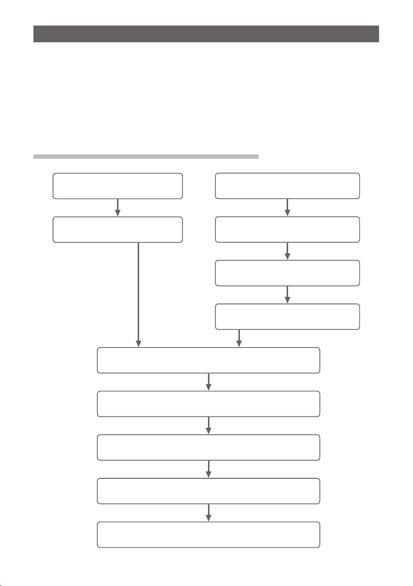
Initial Setup Procedure for APRS Operation.
Using the GPS Function
(See page 3)
Activating the GPS Function
(See page 3)
Setting the Callsign of Your Station
Set the baud rate for APRS and turn ON APRS.
Setting the Symbol of Your Station
Not Using the GPS Function
(See page 3)
Deactivating the GPS Function
(See page 3)
Setting the clock for the transceiver
(Basic Edition See page 33)
Setting the Position of Your Station
(See page 4)
(See page 5)
(See page 7)
(See page 8)
Setting the frequency for B band.
(See page 10)
Setting the APRS beacon transmissions according to
need (See page 26)
2
Page 4
Initial Settings for APRS
®
Operating APRS using the GPS function.
When the GPS function of the transceiver is used, your transceiver’s internal clock
and position are automatically set by the obtained GPS information. If you use
APRS with your transceiver while walking or traveling, the use of the GPS function is
recommended.
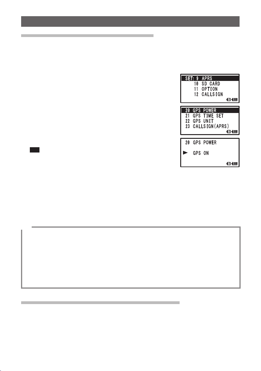
1 Press M over 1 second.
Enters the Set mode.
2 Turn O to select [9 APRS].
3 Press H.
4 Turn O to select [20 GPS POWER].
5 Press H.
6 Turn O to select “ON”.
ON: GPS can be used.
OFF: GPS cannot be used.
Tip Default: ON
7 Press M.
8 Press p.
Exits from the Set mode.
When operating APRS, the position information obtained from GPS can be used for
your transceiver’s position information. Select [9 APRS] [24 MY POSITION] and set
[24 MY POSITION] to [GPS]. If you set the Lat/Lon or P1 to P10 toother than [GPS], the
GPS data is nullified even if it is obtained. The position information designated by this
setting, such as Lat/Lon or P1 to P10, is transmitted.
Tip
• Your own station position Information obtained from GPS can be registered to 10 memory channels
(P1 to P10). The registered position information may then be used to transmit the position of your
own station (See page 63).
• To use the GPS function for APRS operation, select [9 APRS] [24 MY POSITION] and then set
[24 MY POSITION] to [GPS] in the Set mode.
• Using the GPS function increases the consumption current by approximately 30mA. As a result, the
battery life is reduced by about 20% compared to when the GPS function is not used.
• If dual reception is used while APRS is active, weak signals may be inaudible due to noise produced
by the APRS unit.
Operating APRS without using the GPS function.
In order to operate APRS without using the GPS function, set the clock and position
information manually by performing the following steps.
O Setting the clock.
If the internal clock is set, it will be reflected in the time display on the APRS screen. For
details, refer to “Setting clock time” (Basic Operation See page 33).
3
Page 5
Initial Settings for APRS
®
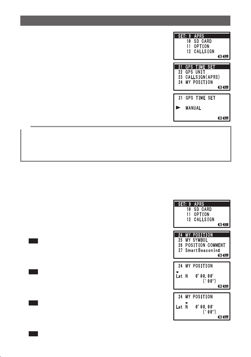
1 Press M over 1 second.
Enters the Set mode.
2 Turn O to select [9 APRS].
3 Press H.
4 Turn O to select [21 GPS TIME SET].
5 Press H.
6 Turn O to select [MANUAL].
7 Press M.
GPS TIME SET is set to MANUAL.
8 Press p.
Exits from the Set mode.
Tip
• I-GATE and Digipeater through connection to a PC cannot be operated.
• You can change the unit of APRS data by selecting [9 APRS] [11 GPS UNIT].
• Even if the internal clock is set to MANUAL, if the GPS function is used, time data will be obtained
from GPS and the precise time will be displayed. This function can be set to OFF (MANUAL) by
selecting [9 APRS] [21 GPS TIME SET].
O Position Information Setting (Datum: WGS-84)
Manually enter the position information of your station.
1 Press M over 1 second.
Enters the Set mode.
2 Turn O to select [9 APRS].
3 Press H.
4 Turn O to select [24 MY POSITION].
5 Press H.
GPS setting items appear on the LCD.
Tip Default: GPS
6 Turn O to select [Lat].
7 Press H.
The cursor moves to setting item for latitude.
Tip Pressing F returns the cursor to the previous item.
8 Turn O to set [N (north latitude)] or [S (south latitude)].
9 Press H.
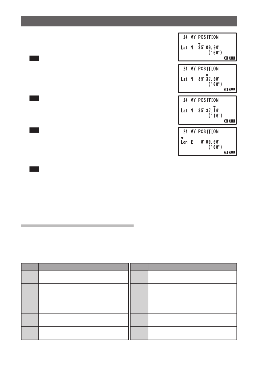
The cursor moves to the setting items for [Degree].
Tip Pressing F returns the cursor to the previous item.
10
Turn O to set [Degree].
11
Press H.
The cursor moves the setting item for [Minute].
Tip Pressing F returns the cursor to the previous item.
4
Page 6
Initial Settings for APRS
12
Turn O to enter [Minute].
13
Press H.
The cursor moves to the setting item for [1/100 minute].
Tip Pressing F returns the cursor to the previous item.
14
Turn O to enter [1/100 Minute].
Seconds will be displayed in parentheses.
15
Press H.
The cursor moves to Lat.
Tip Pressing F returns the cursor to the previous item.
16
Turn O to select [Lon].
17
Press H.
The cursor moves to setting item for longitude.
Tip Pressing F returns the cursor to the previous item.
18
Turn O to set [E (east longitude)] and [W (west
longitude)].
19
Press H.
The cursor moves to the next setting item.
Tip Pressing F returns the cursor to the previous item.
20
Enter [Degree], [Minute], and [1/100 Minute] by following steps 9 through 13.
21
Press M.
The position information is set.
22
Press p.
Exits from the Set mode.
®
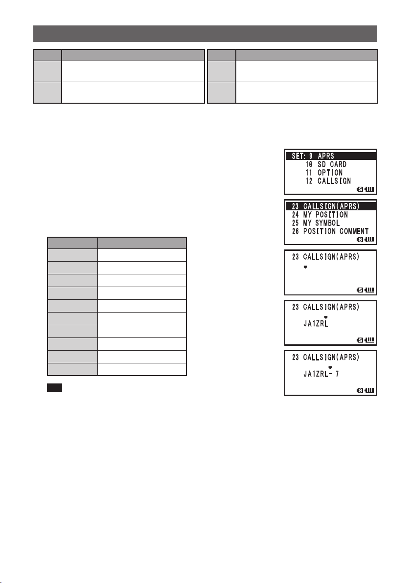
Setting the Callsign of Your Station
Register the callsign of your transceiver for transmitting beacons or transmitting and
receiving messages using APRS. Enter the callsign such as [JA1ZRL-7]. The [–7] of the
callsign represents SSID (Secondary Station Identifier). There are 16 types including no
SSID. Generally, the SSID descriptions shown below are used for APRS.
SSID Description SSID Description
None Fixed station capable of exchanging
messages
1200bps narrow intermediate band
–1
digipeater
9600bps digipeater
–2
1200bps wide band digipeater
–3
Digipeater, mobile station, weather
–4
station, etc.
Operating station such as mobile device
–5
(smartphone)
Maritime mobile station, Land mobile
–8
station
Operating on a mobile device such as
–9
FTM-350 transceiver
I-Gate station, Internet connection station
–10
Flying balloon, airplane, spacecraft, etc.
–11
1-way Tracker (station incapable of
–12
exchanging message)
Weather Station
–13
5
Page 7
Initial Settings for APRS
SSID Description SSID Description
Operating station such as for satellite
–6
communication and event management
Handy type operating station such as
–7
FT1DR transceiver
®
Truck mobile station
–14
digipeater, mobile station, weather
–15
station, etc.
1 Press M over 1 second.
Enters the Set mode.
2 Turn O to select [9 APRS].
3 Press H.
4 Turn O to select [23 CALLSIGN(APRS)].
5 Press H.
6 Enter call sign using numeric keys.
Enter a call sign using numeric keys with reference to the
following table.
Numeric key A, 0(Alphanumeric)
1
2
3
4
5
6
7
8
9
0
1
ABC2
DEF3
GHI4
JKL5
MNO6
PQRS7
TUV8
WXYZ9
0
Tip • When F is pressed, a character is deleted and the cursor
moves to the left.
• Pressing H moves the cursor to the right.
7 Press H to move the cursor.
8 Repeat steps 5 through 7 to enter the call sign.
Up to 6 digits can be entered for the call sign.
[Setting call sign without SSID]
To set an SSID, go to step 11.
9 Press M.
Call sign is registered.
10
Press p.
Exits from the Set mode.
6
Page 8
Initial Settings for APRS
[Setting call sign with SSID]
11
Press H.
12
Turn O to set SSID.
SSID is displayed in [–] after the call sign. It is recommended to select [7] with this
transceiver.
13
Press M to register SSID.
14
Press p.
Exits from the Set mode.
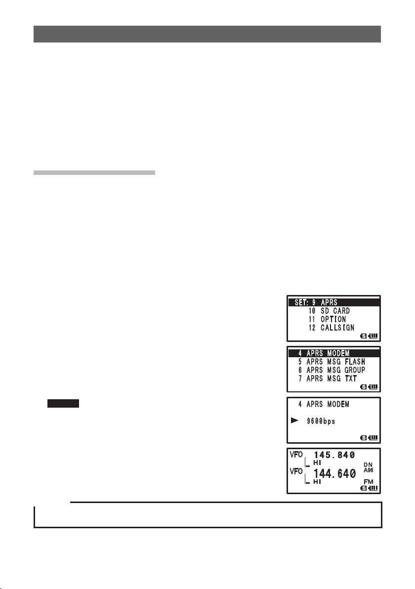
Setting APRS baud rate
Set the baud rate for APRS. If the baud rate is set to 1200bps/9600bps, the APRS
function is activated.
If the baud rate is set to OFF, the APRS functions is deactivated.
Setting the baud rate to 1200bps, the APRS can be operated on AFSK 1200bps
packets.
Setting the baud rate to 9600bps, the APRS can be operated on GMSK 9600bps
packets.
1 Press M over 1 second.
Enters the Set mode.
2 Turn O to select [9 APRS].
3 Press H.
4 Turn O to select [4 APRS MODEM].
5 Press H.
6 Turn O to set APRS baud rate.
The APRS baud rate can be selected form the following 3
types.
[OFF] [1200bps] [9600bps]
Remark Default: OFF
7 Press p to set the APRS baud rate and exit from the Set
mode.
®
Caution
If APRS is not to be operated, select [OFF] by following step 6, shown above.
7
Page 9
Initial Settings for APRS
Tip
• If the baud rate is set to 1200bps/9600bps, the reception save function is automatically deactivated.
• If you set [8 APRS MUTE] to [ON] after selecting [9 APRS] [8 APRS MUTE], [B] band reception
volume (such as beacon and sound) will be muted and [A12] or [A96] will blink.
®
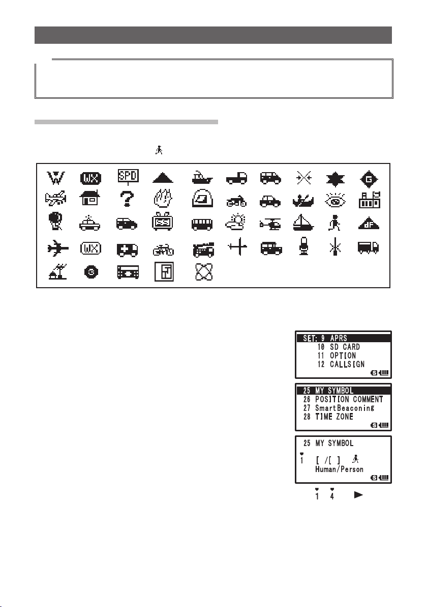
Setting the Symbol of Your Station
Set the symbol for your station to transmit. The symbol can be selected from 45 types.
The default setting symbol is [
].
1 Press M over 1 second.
Enters the Set mode.
2 Turn O to select [9 APRS].
3 Press H.
4 Turn O to select [25 MY SYMBOL].
5 Press H.
MY SYMBOL 1 appears on the LCD.
6 Turn O to select a symbol.
Select between 4 types: [MY SYMBOL 1], [MY SYMBOL
2], [MY SYMBOL 3], or [MY SYMBOL 4].
The symbol for [MY SYMBOL 4] can be directly entered
with characters.
For instructions on how to enter a symbol, see the next
page.
Pressing H changes the number portion of MY SYMBOL from [ ~ ] to [
can be changed to often used symbols (selectable from the frame above).
], and
8
Page 10
Initial Settings for APRS
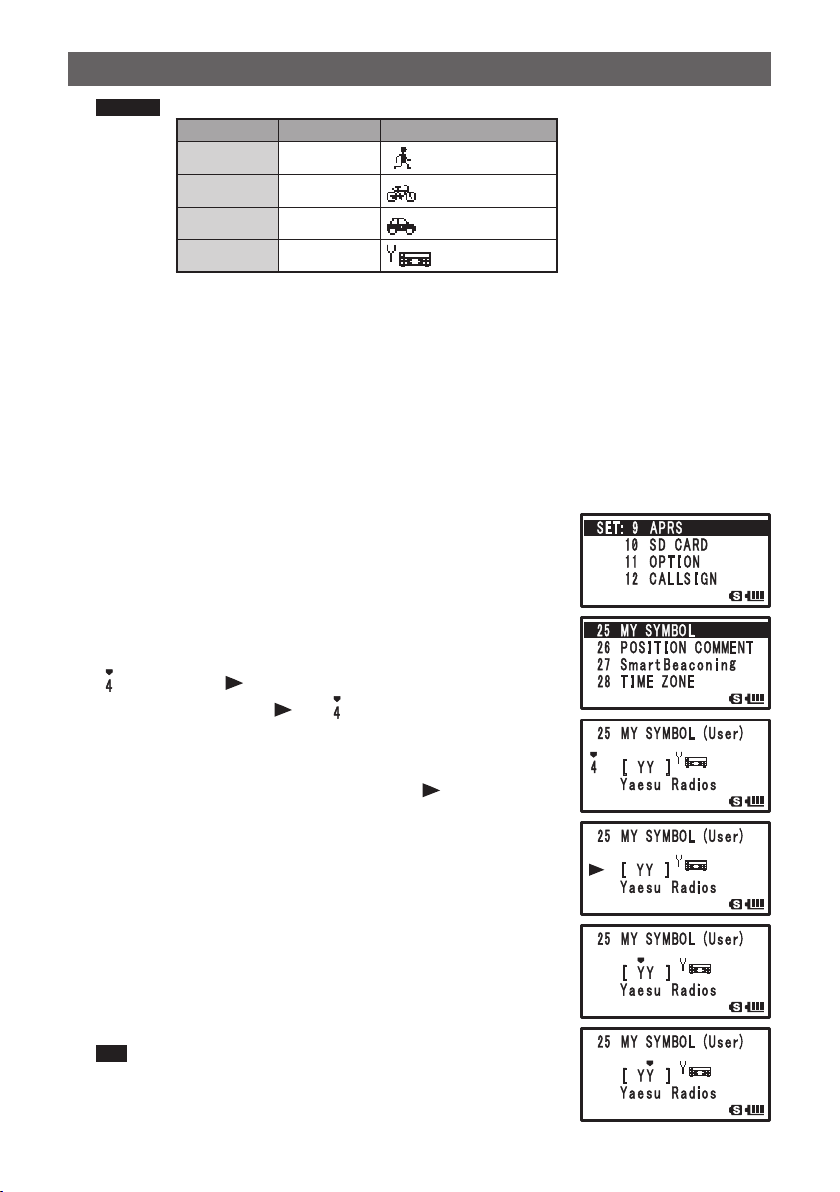
Remark Default value of each symbol is as follows.
MY SYMBOL Code Symbol
1 [ /[ ]
2 [ /b ]
3 [ /> ]
4 [ YY ]
Human/Person
Bicycle
Car
Yaesu Radios
7 Press M.
To set the symbol of your station
8 Press p.
Exits from the Set mode.
O Directly entering symbol characters.
If you do not find any desired symbols, symbol characters can be directly entered.
1 Press M over 1 second.
Enters the Set mode.
2 Turn O to select [9 APRS].
3 Press H.
4 Turn O to select [25 MY SYMBOL].
5 Press H.
6 Turn O to select [MY SYMBOL 4].
7 Press H.
[ ] changes to [
Pressing F returns [
]
] to [ ].
8 Press H.
The cursor moves to Symbol Table ID.
Pressing F returns the cursor back to [
].
9 Turn O to enter characters.
10
Press H.
The cursor moves to the setting items for Symbol Code.
Pressing F moves the cursor back to [Symbol Table ID].
11
Turn O to enter characters.
12
Press M.
The symbol is set.
13
Press p.
Exits from the Set mode.
Tip For the list of latest symbols, see [http://aprs.org/symbols/
symbolsX.txt] or [http://aprs.org/symbols/symbolsnew.txt].
®
9
Page 11
Receiving APRS® beacons
䎭 䎤 䎔 䎽 䎵 䎯
Set the APRS operating frequency before receiving beacons.
Setting the operating frequency for APRS.
The frequency varies between regions and countries.
1 Press A.
Set the operating band to B-band.
APRS can only operate on B-band.
Check that A12 or A96 is displayed in the right edge section of the frequency. (See
page 7).
2 Set the operating frequency.
Tip If the baud rate is set to 1200bps/9600bps in [9 APRS] [4 APRS MODEM], the reception
save function is automatically deactivated.
Receiving APRS® beacons
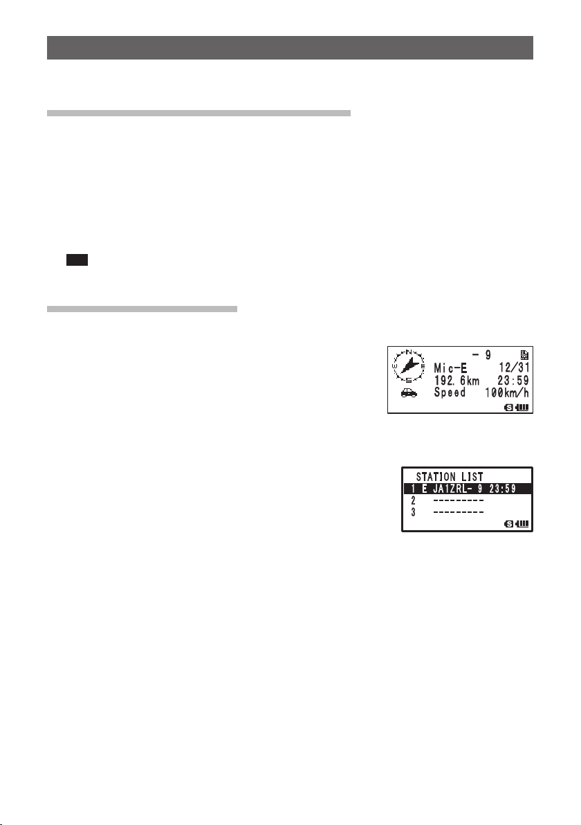
O Displaying received beacons on the APRS popup screen
If a beacon is received while the frequency display screen
is opened, a bell will sound and the APRS popup screen will
appear.
The [APRS POPUP SCREEN] and the [STATION LIST
DESCRIPTION SCREEN] are basically the same.
O Displaying received beacons on the STATION LIST screen
Pressing F then 0 in the frequency display screen
opens the STATION LIST screen.
Pressing 0 key toggles between STATION LIST and
Message LIST screen.
10
Page 12
Receiving APRS® beacons
Description of APRS beacon screen and key operation.
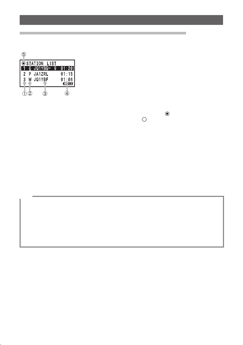
O Description of STATION LIST screen and key operation.
a Number: Received beacons (up to 60) are displayed in the
b Character: The station list character is displayed.
For instructions, see the next page.
c Station name: The call sign of received beacon or Object name/
d Time or date: Time (HH Hours: MM Minute) or Date (MM
The time display will change to the date of the
e Beacon Automatic/Manual Transmission Icon:
O… Scrolls through screen
0… Moves to APRS MESSAGE screen.
D… Moves to MESSAGE EDIT screen.
1… Moves the cursor to the top of STATION LIST.
V… Deletes the selected beacon station on screen. (See page 26)
H… Moves to [STATION LIST] screen (See pages 13 to 21)
M… (Press the key over 1 second) … Set mode (See page 45)
9… Manual transmission of beacon (See page 26)
order received.
Item name is displayed.
Month/DD Day) is displayed.
next day.
Not lit (Manual), if [ ] is lit (AUTO) (See page
27), if [
] is lit (SMART) (See page 27)
Tips
• When a beacon with APRS filter set to [ON] in Set mode option [9 APRS] [3 APRS FILTER] is
received it will appear on the LCD.
If [OFF] is selected, a bell will sound and the beacon is not received.
• When operating on APRS, the received audio (such as beacons and voices) on [B] band, can be
muted in Set mode option [9 APRS] [8 APRS MUTE].
• A bell sound for notifying the reception of an APRS beacon can be set in Set mode option [9 APRS]
[10 APRS RINGER].
If this option is set to [OFF], the bell will not sound.
11
Page 13
Receiving APRS® beacons
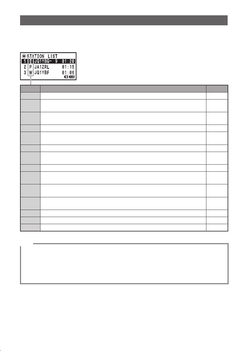
O Description of Station List Characters
This section explains the display examples for the 14 types of station characters.
For details on the description screen, see the next pages listed on the table.
Display Description Page
E EMic-E: Displayed when a beacon from a MIC encoder station is received. 13
Position: Displayed when a beacon from a Fixed Station (FIXED) or Moving Station
P
(MOVING) is received.
Position: Displayed when a beacon from a Fixed Station (fixed) or Moving Station
p
(moving) is received. (Compressed type)
W Weather report: Displayed when a beacon from a weather station is received. 18
Weather report: Displayed when a beacon from a weather station is received.
w
(Compressed type)
O Object: Displayed when a beacon from an object station is received. 19
Object: Displayed when a beacon from an object station is received. (Compressed
o
type)
I Item: Displayed when a beacon from an item station is received. 19
Item: Displayed when a beacon from an item station is received. (Compressed
i
type)
Killed Object/Item: Displayed when a beacon from a deleted object station or item
K
station is received.
Killed Object/Item: Displayed when a beacon from a deleted object stations or item
k
station is received. (Compressed type)
S Status: Displayed when a beacon from a status station is received. 20
? Other: Displayed when a beacon from an unknown station is received. 21
Emg Displayed when a emergency signal from a Mic-E station is received. 13
14 to 16
17
18
19
19
19
19
Tips
• After turning on the power of this transceiver, if the description screen is opened before GPS
information is acquired, the directional arrow and distance measure will not appear.
• If positioning cannot be acquired due to obstacles, such as buildings or tunnels, the position
information of position that was last measured (directional arrow, longitude/latitude, distance
measure) is displayed. Once the transceiver is moved to a position where it can acquire GPS
information, it will resume displaying the accurate position.
12
Page 14
Receiving APRS® beacons
䎭 䎤 䎔 䎽 䎵 䎯
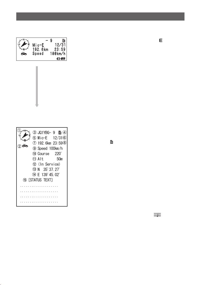
O Explanation of the Detailed Display for Station List of E (Mic-E) and key
operation
O
Screen Details
Pressing H and selecting O station with [ ] in the
STATION LIST will open the details screen for E (Mic-E).
Though only 4 rows are displayed on screen, scrolling
with O reveals the additional information rows.
O… Scrolls through screen
Press F and then turn O… Switches beacon station
Press M… Moves to STATION LIST screen (See page 11).
Press D… Moves to MESSAGE EDITING SCREEN.
Press M over 1 second. … Enters the Set mode (See page 45).
B… Moves to RAW Data display screen (See page 25).
9… Manual transmission of beacon (See page 26).
a Compass (Direction): Shows the direction to the remote transceiver from your
b Symbol: Displays the symbol of the received radio station.
c Callsign: Displays the received call sign.
d Display Message:
e Type Code: Displays the type code being used by the remote
f Date: Displays the Time (HH Hours: MM Minute) or Date (MM
g Distance: Displays the distance between your transceiver and the
h Time: Displays the time (HH Hours: MM Minutes) that the
i Speed: Displays the moving speed of the remote transceiver.
j Direction: Displays the moving direction of the remote transceiver.
k Altitude: Displays the altitude of the remote transceiver.
l Position Comment: Displays the position comment from the remote
m Latitude: The current position is displayed using north (N) or south
n Longitude: The current position is displayed using east (E) or west
o STATUS TEXT: Displays comment information.
transceiver.
mark is displayed when a beacon with STATUS TEXT
is received.
transceiver (such as Mic-E, McE-Trk, McE-Msg, or
model name of the transceiver).
Month/DD Day).
remote transceiver.
beacon was received.
transceiver. If Emergency is received, (Emergency) is
displayed on screen and a beep [
sounded 12 times.
(S) latitude (DD degree, MM.MM minutes, or DD degree,
MM minutes, SS seconds).
(S) longitude (DDD degree, MM.MM minutes, or DD
degrees, MM minutes, SS seconds).
] is repeatedly
13
Page 15
Receiving APRS® beacons
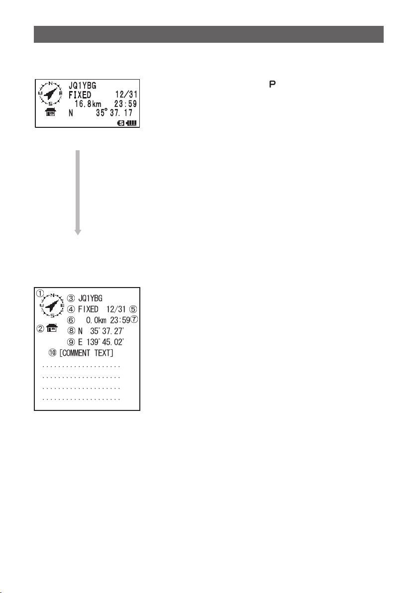
O Explanation of the Detailed Display for Station List of P (Position: Fixed Station)
and key operation.
Pressing H and selecting [ ] station with O in the
STATION LIST screen will open the detail screen for P
(Position).
Though only 4 rows are displayed on the screen, scrolling
with O will reveal the additional rows of information.
O… Scrolls trough screen
Press F after pressing O… Transition of beacon station
Press M… Moves to STATION LIST screen (See page 11).
O
Press D… Moves to MESSAGE EDIT screen.
Press M over 1 second… Enters the Set mode. (See page 45).
B… Moves to RAW Data display screen (See page 25).
9… Manual transmission of beacon (See page 26).
Screen Details
a Compass (Direction): Shows the direction to the remote transceiver from your
transceiver.
b Symbol: Displays the symbol of the received radio station.
c Callsign: Displays the received call sign.
d Remote transceiver information:
Displays information on the fixed station (FIXED).
e Date: Displays the Time (HH Hours: MM Minute) or Date (MM
Month/DD Day).
f Distance: Displays the distance between your transceiver and the
remote transceiver.
g Time: Displays the time (HH Hours: MM Minutes) that beacon
was received.
h Latitude: The current position is displayed using north (N) or south
(S) latitude (DD degree, MM.MM minutes, or DD degree,
MM minutes, SS seconds).
i Longitude: The current position is displayed using east (E) or west
(S) longitude (DD D degree, MM.MM minutes, or DD
degree, MM minutes, SS seconds).
j STATUS TEXT: Displays comment information.
14
Page 16
Receiving APRS® beacons
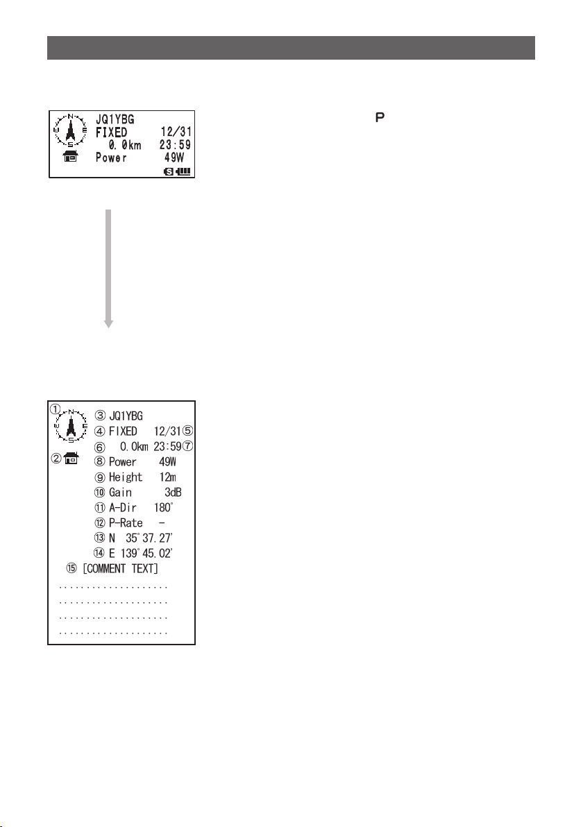
O Explanation of Display details and key operations for Station List of P (Position:
Fixed Station).
Pressing H and selecting [ ] station with O in the
STATION LIST will open the detail screen for P (Position).
Position may contain detailed information called PHG
code in some cases.
Though only 4 rows are displayed on screen, scrolling
with O will reveal the additional rows of information.
O… Scroll through screen
Press F after pressing O… Switches beacon station
O
Press M… Moves to STATION LIST screen (See page 11).
Press D… Moves to MESSAGE EDIT screen.
Press M over 1 second… Enters the Set mode. (See page 45).
B… Moves to RAW Data display screen (See page 25).
9… Manual transmission of beacon (See page 26).
Screen Details
a Compass (Direction): Shows the direction to the remote transceiver from your
transceiver.
b Symbol: Displays the symbol of the received radio station.
c Callsign: Displays the received call sign.
d Remote transceiver information:
Displays information on the fixed station (FIXED).
e Date: Displays the Time (HH Hours: MM Minute) or Date (MM
Month/DD Day).
f Distance: Displays the distance between your transceiver and the
remote transceiver.
g Time: Displays the time (HH Hours: MM Minutes) that beacon
was received.
h Transmission Power: Displays transmission power of the remote transceiver.
i Antenna ground clearance:
Displays the antenna ground clearance of the remote
transceiver.
j Antenna gain: Displays antenna gain of the other station.
k Antenna direction: Displays the antenna direction of the remote transceiver.
l Transmission count: Displays the number of transmission from the remote
transceiver.
m Latitude: The current position is displayed using north (N) or south
(S) latitude (DD degree, MM.MM minutes, or DD degree,
MM minutes, SS seconds).
n Longitude: The current position is displayed using east (E) or west
(S) longitude (DDD degree, MM.MM minutes, or DD
degree, MM minutes, SS seconds).
o STATUS TEXT: Displays comment information.
15
Page 17
Receiving APRS® beacons
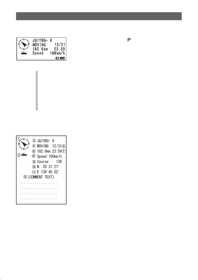
O Explanation of Display details and key operations for Station List of P (Position:
Fixed Station).
Pressing H and selecting [ ] station with O in the
STATION LIST will open the detail screen for P (Position).
If there is information related to movement (Speed,
Course) in data received, it is displayed as shown below.
Though only 4 rows are displayed on the screen, scrolling
with O will reveal the additional rows of information.
O… Scrolls through screen
Press F after pressing O… Switches beacon station
O
Press M… Moves to STATION LIST screen (See page 11).
Press D… Moves to MESSAGE EDIT screen.
Press M over 1 second … Enters the Set mode. (See page 45).
B… Moves to RAW Data display screen (See page 25).
9… Manual transmission of beacon (See page 26).
Screen Details
a Compass (Direction): Shows the direction to the remote transceiver from your
transceiver.
b Symbol: Displays the symbol of the received radio station.
c Callsign: Displays the received call sign.
d Remote transceiver information:
Displays information on the fixed station (FIXED).
e Date: Displays the Time (HH Hours: MM Minute) or Date (MM
Month/DD Day).
f Distance: Displays the distance between your transceiver and the
remote transceiver.
g Time: Displays the time (HH Hours: MM Minutes) that beacon
was received.
h Speed: Displays the moving speed of the remote transceiver.
i Direction: Displays the moving direction of the remote transceiver.
j Latitude: The current position is displayed using north (N) or south
(S) latitude (DD degree, MM.MM minutes, or DD degree,
MM minutes, SS seconds).
k Longitude: The current position is displayed using east (E) or west
(S) longitude (DDD degree, MM.MM minutes, or DD
degree, MM minutes, SS seconds).
l STATUS TEXT: Displays comment information.
16
Page 18
Receiving APRS® beacons
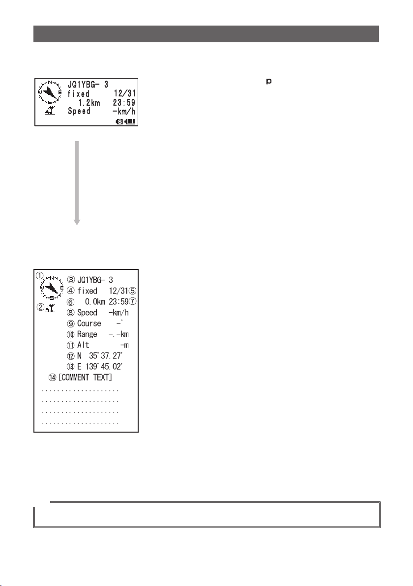
O Explanation of the Detailed Display and key operations for Station List of p
(Position: Fixed Station).
Pressing H and selecting [ (Position Compressed
type)] station with O in the STATION LIST screen will
open the details screen for P (Position).
Though only 4 rows are displayed on screen, scrolling
with O will reveal the additional rows of information.
O… Scrolls trough screen
Press F after pressing O… Switches beacon station
O
Press M… Moves to STATION LIST screen (See page 11).
Press D… Moves to MESSAGE EDITING SCREEN.
Press M over 1 second … Enters the Set mode (See page 45).
B… Moves to RAW Data display screen (See page 25).
9… Manual transmission of beacon (See page 26).
Screen Details
a Compass (Direction): Shows the direction to the remote transceiver from your
transceiver.
b Symbol: Displays the symbol of the received radio station.
c Callsign: Displays the received call sign.
d Remote transceiver information:
Displays information on the fixed station (FIXED).
e Date: Displays the Time (HH Hours: MM Minute) or Date (MM
Month/DD Day).
f Distance: Displays the distance between your transceiver and the
remote transceiver.
g Time: Displays the time (HH Hours: MM Minutes) that beacon
was received.
h Speed: Displays the moving speed of the remote transceiver.
i Direction: Displays the moving direction of the remote transceiver.
j Radio wave reaching range:
Displays information on the radio wave reaching range
of the remote transceiver.
k Latitude: The current position is displayed using north (N) or south
(S) latitude (DD degree, MM.MM minutes, or DD degree,
MM minutes, SS seconds).
l Longitude: The current position is displayed using east (E) or west
(S) longitude (DDD degree, MM.MM minutes, or DD
degree, MM minutes, SS seconds).
m STATUS TEXT: Displays comment information.
Tip
Compressed type beacon is a beacon sent in a format where a part of the information is compressed.
17
Page 19
Receiving APRS® beacons
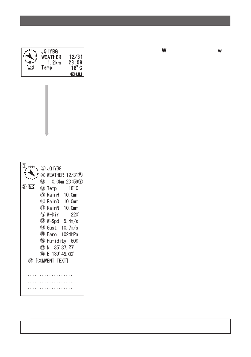
O Explanation of the Detailed Display for Station List of W (Weather report:
Weather Station) and key operation.
Pressing H and selecting [ ] (Weather report) or [ ]
(Weather report Compressed type) station with O in the
STATION LIST screen will open the details screen for W
or w (Weather report). Though only 4 rows are displayed
on screen, scrolling with O shows all the information.
O… Scrolls trough screen
Press F after pressing O… Switches beacon station
O
Press M… Moves to STATION LIST screen (See page 11).
Press D… Moves to MESSAGE EDITING SCREEN.
Press M over 1 second … Enters the Set mode (See page 45).
B… Moves to RAW Data display screen (See page 25).
9… Manual transmission of beacon (See page 26).
Screen Details
a Compass (Direction): Shows the direction to the remote transceiver from your
b Symbol: Displays the symbol of the received radio station.
c Callsign: Displays the received call sign.
d Remote transceiver information:
e Date: Displays the Time (HH Hours: MM Minute) or Date (MM
f Distance: Displays the distance between your transceiver and the
g Time: Displays the time (HH Hours: MM Minutes) that beacon
h Temperature: Displays temperature information.
i Precipitation: Displays information on precipitation per hour.
j Precipitation: Displays information on precipitation per 24 hours.
k Precipitation: Displays information on precipitation from midnight.
l Wind direction; Displays information on wind direction.
m Wind speed: Displays information on wind speed.
n
Maximum wind speed:
o
Atmospheric pressure:
p Humidity: Displays information on humidity.
q Latitude: The current position is displayed using north (N) or south
r Longitude: The current position is displayed using east (E) or west
s STATUS TEXT: Displays comment information.
transceiver.
Displays information on the fixed station (FIXED).
Month/DD Day).
remote transceiver.
was received.
Displays information on the maximum wind speed.
Displays information on atmospheric pressure.
(S) latitude (DD degree, MM.MM minutes, or DD degree,
MM minutes, SS seconds).
(S) longitude (DDD degree, MM.MM minutes, or DD
degree, MM minutes, SS seconds).
Tip
Compressed type beacon is a beacon sent in a format where a part of the information is compressed.
18
Page 20
Receiving APRS® beacons
䎼 䎤 䎨 䎶 䎸
䎼䎤䎨 䎶䎸
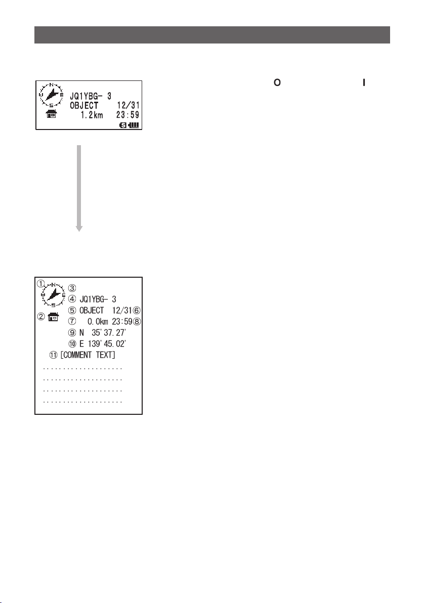
O Explanation of the Detailed Display and key operations for Station List of O
(Object) or I (Item).
Pressing H and selecting [ (Object)] station or [
(Item)] station with O in the STATION LIST screen will
open the details screen for O (Object) or I (Item).
Though only 4 rows are displayed on screen, scrolling
with O will reveal the additional rows of information.
O… Scrolls trough screen
Press F after pressing O… Switches beacon station
O
Press M… Moves to STATION LIST screen (See page 11).
Press D… Moves to MESSAGE EDITING SCREEN.
Press M over 1 second … Enters the Set mode (See page 45).
B… Moves to RAW Data display screen (See page 25).
9… Manual transmission of beacon (See page 26).
a
Screen Details
Compass (Direction):
Symbol:
b
c
d
e
f
g
h
i
j
k
Displays the symbol of the received radio station.
Name:
Displays the name of the Object or Item.
Callsign:
Displays the received call sign.
Remote transceiver information:
Date:
Displays the Time (HH Hours: MM Minute) or Date (MM
Distance:
Time:
Displays the time (HH Hours: MM Minutes) that beacon
Latitude:
The current position is displayed using north (N) or south
Longitude:
STATUS TEXT:
Shows the direction to the remote transceiver from your
transceiver.
Displays information on the fixed station (FIXED).
Month/DD Day).
Displays the distance between your transceiver and the
remote transceiver.
was received.
(S) latitude (DD degree, MM.MM minutes, or DD degree,
MM minutes, SS seconds).
The current position is displayed using east (E) or west
(S) longitude (DDD degree, MM.MM minutes, or DD
degree, MM minutes, SS seconds).
Displays comment information.
19
Page 21
Receiving APRS® beacons
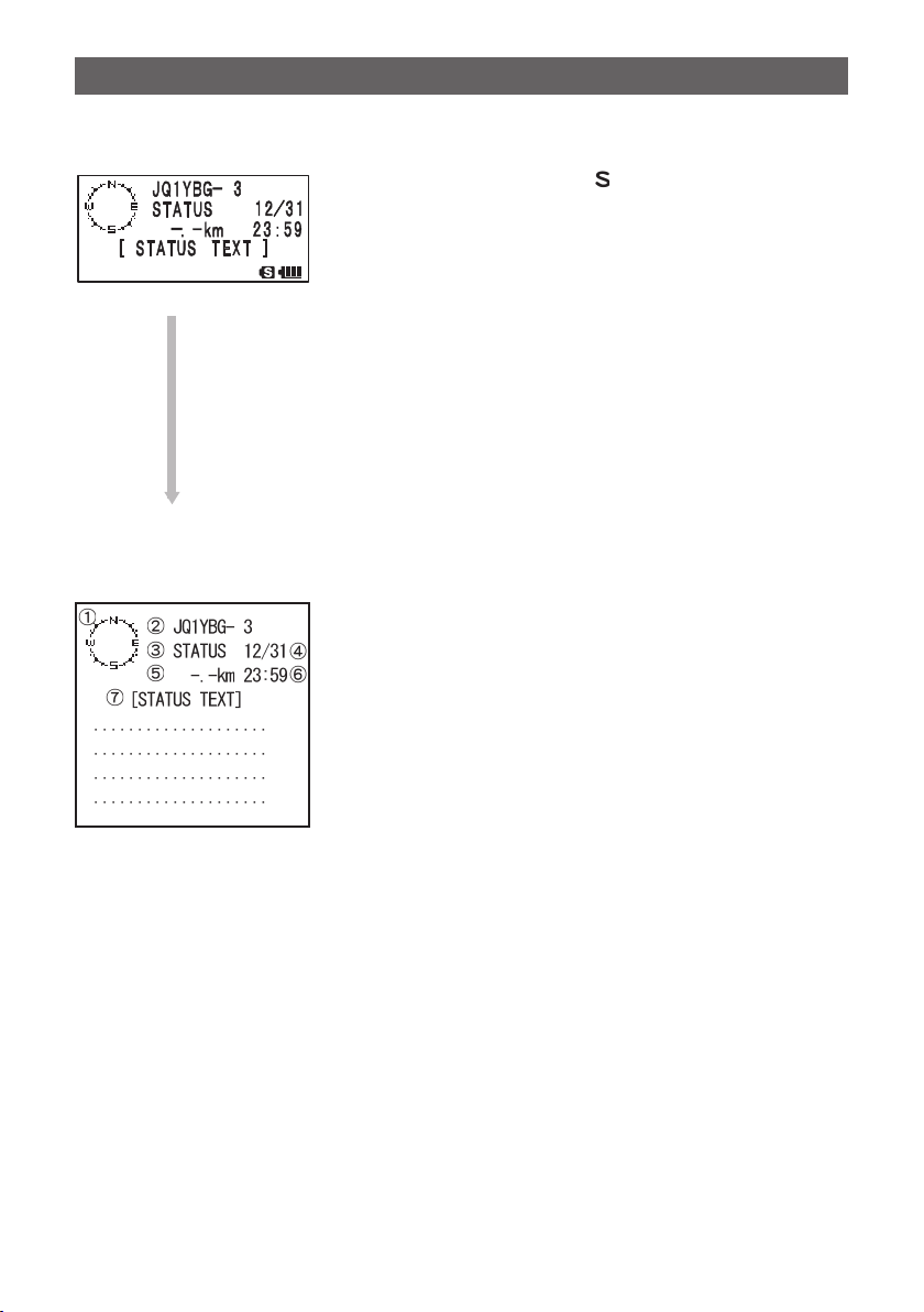
O Explanation of the Detailed Display and key operations for Station List of S
(Status).
Pressing H and selecting [ (Status)] station with O
in the STATION LIST will open the details screen for S
(Status).
Though only 4 rows are displayed on screen, scrolling
with O shows all the information.
O… Scrolls trough screen
Press F after pressing O… Switches beacon station
O
Press M… Moves to STATION LIST screen (See page 11).
Press D… Moves to MESSAGE EDITING SCREEN.
Press M over 1 second … Enters the Set mode (See page 45).
B… Moves to RAW Data display screen (See page 25).
9… Manual transmission of beacon (See page 26).
Screen Details
a Compass (Direction): Shows the direction to the remote transceiver from your
transceiver.
b Callsign: Displays the received call sign.
c Remote transceiver information:
Displays information on the fixed station (FIXED).
d Date: Displays the Time (HH Hours: MM Minute) or Date (MM
Month/DD Day).
e Distance: Displays the distance between your transceiver and the
remote transceiver.
f Time: Displays the time (HH Hours: MM Minutes) that beacon
was received.
g STATUS TEXT: Displays comment information.
20
Page 22

Receiving APRS® beacons
O Explanation of the Detailed Display and key operations for Station List of ?
(Other).
Pressing H and selecting [ ] (Other) station with O
in the STATION LIST will open the details screen for ?
(Other).
This symbol is displayed when a packet that could not be
deciphered as a APRS beacon is received.
Though only 4 rows are displayed on the screen, scrolling
with O will reveal the additional rows of information.
O… Scrolls trough screen
O
Press F after pressing O… Switches beacon station
Press M… Moves to STATION LIST screen (See page 11).
Press D… Moves to MESSAGE EDITING SCREEN.
Press M over 1 second … Enters the Set mode (See page 45).
B… Moves to RAW Data display screen (See page 25).
9… Manual transmission of beacon (See page 26).
Screen Details
a Compass (Direction): Shows the direction to the remote transceiver from your
transceiver.
b Callsign: Displays the received call sign.
c Remote transceiver information:
Displays information on the fixed station (FIXED).
d Date: Displays the Time (HH Hours: MM Minute) or Date (MM
Month/DD Day).
e Distance: Displays the distance between your transceiver and the
remote transceiver.
f Time: Displays the time (HH Hours: MM Minutes) that beacon
was received.
g DATA TEXT: Displays the packet data that could not be deciphered as
APRS beacon.
Notification of beacons or messages with a popup screen. APRS POPUP Function
A popup display can be set to notify the reception of APRS beacons or messages from
the remote station.
1 Press M over 1 second.
Enters the Set mode.
2 Turn O to select [9 APRS].
3 Press H.
4 Turn O to select [9 APRS POPUP].
5 Press H.
21
Page 23

Receiving APRS® beacons
6 Turn O to select setting item.
For details on each item, refer to Set mode Function List
(See page 50).
Mic-E: OFF / ALL2s to ALL60s / ALLCNT / BND2s to
BND60s / BNDCNT
POSITION: OFF / ALL2s to ALL60s / ALLCNT / BND2s to
BND60s / BNDCNT
WEATHER: OFF / ALL2s ~ ALL60s / ALLCNT / BND2s to
BND60s / BNDCNT
OBJECT: OFF / ALL2s to ALL60s / ALLCNT / BND2s to BND60s / BNDCNT
ITEM:OFF / ALL2s to ALL60s / ALLCNT / BND2s to BND60s / BNDCNT
STATUS: OFF / ALL2s to ALL60s / ALLCNT / BND2s to BND60s / BNDCNT
OTHER: OFF / ALL2s to ALL60s / ALLCNT / BND2s to BND60s / BNDCNT
MY PACKET: OFF / ALL2s ~ ALL60s / ALLCNT / BND2s to BND60s / BNDCNT
MSG: OFF / ALL2s ~ ALL60s / ALLCNT / BND2s ~ BND60s / BNDCNT
GRP: OFF / ALL2s ~ ALL60s / ALLCNT / BND2s ~ BND60s / BNDCNT
BLN: OFF / ALL2s ~ ALL60s / ALLCNT / BND2s ~ BND60s / BNDCNT
MY MSG: OFF / BND2s to BND60s / BNDCNT
DUP.BCN: OFF / BND2s to BND60s / BNDCNT
DUP.MSG: OFF / BND2s to BND60s / BNDCNT
ACK.REJ: OFF /BND2s to BND60s / BNDCNT
OTHER MSG: OFF /BND2s ~ BND60s / BNDCNT
7 Press H.
8 Turn O to select a setting value.
9 Press M.
10
Turn O to select setting item.
Turn O to select next setting item.
11
Press H.
12
Repeat steps 6 to 11 to set remaining items.
13
Press p.
Exits from the Set mode.
22
Page 24

Receiving APRS® beacons
䰢䰒䰛
䰒䰙
䰔 䰕
䰔 䰕
䎱䎨 䎭䎤䎔䎽䎵䎯
䎐䎃䎃䎃䎚
䯽䰀䰀䯺䎙䎗䯼
Screen when BND2s to BND60s is selected
If a beacon or message from the remote station is received when [BND2s to BND60s] is
selected for APRS POPUP, a screen like shown below is displayed.
䰢䰒䰛
䯽䰀䰀
䰔䰕
2 alphabetic characters
are displayed.
䰔䰕
The alphabetic characters displayed next to the callsign of the remote station signifies
the following meanings.
st
1
character
N = New: New signal
D = Duplicate: Signal that has already been received
A = ACK: ACK signal of a message (See page 43)
R = Reject: REJ signal of a message (See page 37)
nd
2
character
E = Mic-E: Beacon of a MIC encoder station.
P = Position: Beacon of a Fixed station (FIXED) or a Moving Station (MOVING)
P = Position: Beacon of a Fixed station (fixed) or a Moving Station (moving)
(compressed type).
W = Weather report: Beacon of a weather station
w = Weather report: Beacon of a weather station (compressed type).
O = Object: Beacon of an object station
o = Object: Beacon of an object station (compressed type)
I = Item: Beacon of an item station
i = Item: Beacon of an item station (compressed type)
K = Killed Object or Item: Erased object station or item station.
k = Killed Object or Item: Erased object station or item station (compressed type).
S = Status: Beacon of a status station
? = Other: Beacon that could not be deciphered
䎐䎃䎃
䰒䰙
23
Page 25

Receiving APRS® beacons
Notification of beacon or message reception with a ringer sound. APRS RINGER Function
A ringer sound can be set to notify the reception of APRS beacons or messages from
the remote stations.
1 Press M over 1 second.
Enters the Set mode.
2 Turn O to select [9 APRS].
3 Press H.
4 Turn O to select [10 APRS RINGER].
5 Press H.
6 Turn O to select setting item.
For details on each item, refer to Set mode Function List
(See page 52).
Mic-E: ON/OFF
POSITION: ON/OFF
WEATHER: ON/OFF
OBJECT: ON/OFF
ITEM: ON/OFF
STATUS: ON/OFF
OTHER: ON/OFF
MY PACKET: ON/OFF
MSG: ON/OFF
GRP: ON/OFF
BLN: ON/OFF
MY MSG: ON/OFF
DUP.BCN: ON/OFF
DUP.MSG: ON/OFF
ACK.REJ: ON/OFF
OTHER MSG: ON/OFF
TX BCN: ON/OFF
TX MSG: ON/OFF
7 Press H.
8 Turn O to select [ON] or [OFF].
9 Press M.
10
Turn O to select setting item.
Turn O to select next setting item.
11
Press H.
12
Repeat steps 6 to 11 to set remaining items.
13
Press p.
Exits from the Set mode.
24
Page 26

Receiving APRS® beacons
Displaying RAW packet data
Display packet data (raw data) received from the remote station on the STATION LIST
details screen.
1 Press F and then 0.
The STATION LIST screen appears.
2 Turn O to select a beacon station.
Select the beacon station to see the RAW packet data received from it.
3 Press H.
The STATION LIST detail screen is displayed on the LCD.
4 Press M.
RAW packet data is displayed on the LCD.
5 Press O to scroll the screen display.
Tip After you have pressed F, you can change the beacon being displayed by turning O while
f is displayed on the LCD.
6 Press B.
STATION LIST detail screen appears.
STATION LIST details screen
Details of the RAW Packet Data display screen
a Destination Information: Displays the destination address information of AX.25 packet.
b Digipeater Information: Displays the information of repeater station (Digipeater).
c RAW TEXT: Displays the text of raw data
Tip
• DIGI (First) and DIGI (Last) are not displayed because Digipeater information is not saved for
transmission message. (“–” is displayed instead)
• When a 3rd Party Header Beacon (beacon from I-Gate, etc.) is received, the route information
included in the 3rd Party Header Beacon is displayed, not that obtained from the AX.25 packet
signal.
25
Page 27

Receiving APRS® beacons
Deleting beacon stations from the list
Delete unnecessary beacon stations from the STATION LIST by selecting them on the
STATION LIST screen.
1 Press F and then 0.
The STATION LIST screen appears.
2 Turn O to select a call sign to delete. Scroll the screen
display and select a call sign to delete.
3 Press V.
The confirmation message [DELETE?] appears on the
LCD.
Tip Pressing a key other than H cancels the deletion.
4 Press H.
The selected CALLSIGN is deleted from the list.
Transmitting the APRS® beacon
Manually transmitting a beacon
Press F and then 9. (in case of frequency screen)
1
Press 9 on the STATION LIST and STATION LIST Details screens.
To transmit beacons automatically, set [AUTO] or [SMART] in the next instruction,
“Switching between manual and automatic transmission of beacon”.
Tip
• If [DUP.BCN] is set to ON in [APRS] [10 APRS RINGER], a bell will sound when your station
beacon relayed by a digipeater is received.
• To use the GPS function for APRS operation, check that the Set mode option [9 APRS] [24 MY
POSITION] has been set to [GPS].
Beacon cannot be transmitted if the GPS data cannot be received.
Switching between manual and automatic beacon transmission
Set the APRS beacon for manual or Automatic transmission.
1 Press F and then 0.
The STATION LIST screen appears.
2 Press B.
Pressing the B key toggles between [MANUAL], [AUTO], and [SMART].
The shortcut key for this operation is [9 APRS] [16 BEACON TX].
26
Page 28

Transmitting the APRS® beacon
Icon is off (MANUAL): APRS beacon of your station is only
For transmission on the frequency
is continually lit (AUTO): APRS beacon of your station is
is continually lit (SMART):
*1: In APRS set mode option [9 APRS] [14 BEACON INTERVAL], the interval for transmission can
be set.
*2: • For details on the SmartBeaconing function, see page 28.
• This setting can only be selected if: STATUS setting in [9 APRS] [27 SmartBeaconing] is set
between Type 1 and Type 3, and [9 APRS] [24 MY POSITION] is set to GPS.
transmitted when 9 is pressed
(default setting).
screen, press F then 9.
transmitted automatically every 5
minutes.*
APRS beacon is sent automatically
using the SmartBeaconing function.*
1
Icon is off (MANUAL):
is continually lit (AUTO):
is continually lit (SMART):
2
Tip
In Set mode option [9 APRS] [12 APRS TX DELAY], the data transmission delay time can be
changed.
Set the automatic transmission interval for sending a beacon
Set the time interval for automatically transmitting the APRS beacon.
1 Press M over 1 second.
Enters the Set mode.
2 Turn O to select [9 APRS].
3 Press H.
4 Turn O to select [14 BEACON INTERVAL].
5 Press H.
6 Turn O to select the automatic transmission interval.
Select an automatic transmit interval from the following:
30sec/1min/2min/3min/5min/10min/15min/20min/
30min/60min
Tip Default: 5 minutes
7 Press M.
The automatic beacon transmit interval is set.
8 Press p.
Exits from the Set mode.
27
Page 29

Transmitting the APRS® beacon
Tip
• When the APRS beacon transmit is changed to [AUTO], the timer for the automatic beacon transmit
interval is reset, and the count for the automatic beacon interval begins.
When the set time is reached, the initial beacon will be transmitted.
• Even in automatic (AUTO) beacon transmit, transmission of the beacon can be forced by
pressing F then 9 while operating with the frequency screen displayed. (Press 9 while
the STATION LIST screen or the STATION LIST Details screen is displayed to force a beacon
transmission).
A forced beacon transmission will reset the automatic transmit timer.
• If the set time is reached during automatic beacon transmit, but the squelch is active, the beacon
transmission is withheld.
When the squelch is deactivated, the beacon is transmitted.
Setting SmartBeaconing™
The SmartBeaconing function efficiently transmits/beacons the position information of
your station, based on data obtained from the GPS unit.
This transceiver can support automatic beacon information with the SmartBeaconing
function.
The SmartBeaconing function on this transceiver has 3 different settings (TYPE 1 to
TYPE 3) and has preset initial values postulated to be used in the following operations.
TYPE1: High speed movement, such as by vehicle.
TYPE2: Medium speed movement, such as by bicycle.
TYPE3: Low speed movement, such as by walking.
TYPE 2 and TYPE 3 settings (particularly TYPE 3) transmit many beacons in a short
period of time, even if movement is comparatively slow.
Because of this, using these setting during high speed movement, such as by vehicle,
causes many beacons to be transmitted, and may cause signal congestion on the
frequency.
Be sure to use TYPE1 settings when in high-speed movement.
If SmartBeaconing is to be operated at different timings, parameters of settings TYPE1
to TYPE3 can be changed. When changing parameters, be sure to adjust parameters of
SmartBeaconing and DIGI PATH settings for appropriate beacon transmission intervals
to avoid signal congestion on the APRS frequency.
1 Press M over 1 second.
Enters the Set mode.
2 Turn O to select [9 APRS].
3 Press H.
4 Turn O to select [27 SmartBeaconing].
5 Press H.
28
Page 30

Transmitting the APRS® beacon
6 Press H again and select TYPE by turning O.
Select a TYPE from the following:
OFF: Deactivates the SmartBeaconing function
TYPE1: Settings recommended for high-speed movement such as by vehicle.
TYPE2: Settings recommended for medium speed movement such as by bicycle.
TYPE3: Settings recommended for low speed movement such as walking.
7 Press M.
The selected TYPE is set.
8 Press p.
Exits from the Set mode.
9 Press F and then 0.
The STATION LIST screen appears.
10
Press B twice.
is lit on the top-left of the LCD.
This the shortcut to [9 APRS] [16 BEACON TX].
SmartBeaconing is set when
Tip
• If SMART is selected in [9 APRS] [16 BEACON TX], settings for BEACON INTERVAL are
ignored.
• This function can only be selected if: STATUS setting in [9 APRS] [27 SmartBeaconing] is set
between Type 1 and Type 3, and [9 APRS] [24 MY POSITION] is set to GPS.
is lit on the top-left of the LCD.
* SmartBeaconing is provided by HamHUD Nichetronix, LLC.
Status Text Register
5 different status texts of up to 60 characters can be registered.
1 Press M over 1 second.
Enters the Set mode.
2 Turn O to select [9 APRS].
3 Press H.
4 Turn O to select [15 BEACON STATS TXT].
5 Press H.
6 Turn O to select [S.TXT].
7 Press H.
8 Turn O to select ON/OFF.
Turn status text ON or OFF.
9 Press M.
10
Turn O to select [TX RATE].
29
Page 31

Transmitting the APRS® beacon
11
Press H.
TX RATE is for setting how frequently status texts are sent
when APRS beacons are transmitted.
12
Turn O to select [TX RATE].
Select between 1/1 (every time) to 1/8 (once every 8 times)
13
Press M.
14
Turn O to select the number for status text.
15
Press H.
16
Turn O to select the number for registering status text.
If there is already a text registered to that number, the first
16 characters of that text will be displayed.
17
Press H.
The text editing screen appears. Press M to go back to the previous screen.
18
Enter the characters using keypad keys.
Enter STATUS TEXT using keypad keys, referring to the following table.
Numeric key A, 0 (Alphanumeric)
1
2
3
4
5
6
7
8
9
0
1
abc2ABC
def3DEF
ghi4GHI
jkl5JKL
mno6MNO
pqr7PQRS
tuv8TUV
wxyz9WXYZ
0
Tip • When F is pressed, a character is deleted and the cursor moves to the left.
• Pressing H moves the cursor to the right.
• Single Characters can also be entered by turning O.
• To delete all characters to the right of the cursor, Select [CLR] by pressing A, then V.
• To insert a single character into the text. select [INSERT] by pressing A, then V.
• To delete all characters, select [CLRALL] by pressing A, then V.
• To delete the character where the cursor is positioned, select [DELETE] by pressing A,
then V,
19
Repeat steps 17 and 18 to enter the STATUS TEXT.
20
Press M.
The characters are entered.
30
Page 32

Transmitting the APRS® beacon
21
Press p.
Exits from the Set mode.
The status text registered last is transmitted.
When entering the status text, a : (colon) appears on the
st
21
character, the 29 character, and the 43rd character.
If text exceeding the position a : (colon) appears, some
transceivers may not be able to display the entire message
upon reception. Try to enter a text shorter than where :
(colons) appear if possible.
Select a Position Comment
Select the position comment (standard message) incorporated into beacons of your
station.
1 Press M over 1 second.
Enters the Set mode.
2 Turn O to select [9 APRS].
3 Press H.
4 Turn O to select [26 POSITION COMMENT].
5 Press H.
6 Turn O to select a position comment.
Select a position comment from the following.
Off Duty/En Route/In Service/Returning/Committed/
Special/Priority/Custom 0 to Custom 6/EMERGENCY!
Remark Default: Off Duty
Tip • Only when [EMERGENCY!] is selected in step 6, a confirmation
message: [OK?] appears when M is pressed and a bell will
sound three times upon confirmation.
• To cancel the position comment, turn O and select a different
comment.
7 Press M to register a position comment.
8 Press p.
Exits from the Set mode.
Caution
Unless there is a serious emergency such as an accident or natural disaster, do not slelect
[EMERGENCY!].
31
Page 33

Transmitting the APRS® beacon
Setting the Digipter Route
A station that relays transmissions such as beacons is called a digipeater.
In order to use a digipeater, register the callsign or ALIAS of the digipeater to your
transceiver.
This transceiver is preset to [WIDE1-1] (relay setting for 1 position) and [WIDE1-1,
WIDE2-1] (relay setting for 2 positions).
In [WIDE1-1, WIDE2-1], a transmission is relayed to the first digipeater station specified
as WIDE1-1, then to the second digipeater station specified as WIDE2-1.
In this setting, transmission is relayed by digipeaters in 2 positions.
As of January 2013, digipeater stations used by APRS are recommended to be
operated using *New-N Paradigm.
The initial values set to this transceiver are those premised on the NEW-N Paradigm
method for digipeater station operation.
In order to use other methods of relaying messages, select between P4 and P8 and
enter the CALLSIGN or ALIAS of the relay station (enter these by following the steps
below).
* For information on the New-N Paradigm method, see the website below for details.
http://aprs.org/fix14439.html (as of January 2013)
Caution
If too many relay nodes are set, a beacon sent by one station is repeatedly relayed and can cause
communications channel congestion.
Try to operate DIGI PATH without changing settings unless necessary.
1 Press M over 1 second.
Enters the Set mode.
2 Turn O to select [9 APRS].
3 Press H.
4 Turn O to select [18 DIGI PATH].
5 Press H.
6 Turn O to select [DIGI PATH].
Select a DIGI PATH from between P1 to P8.
P1 (OFF), P2 (WIDE1-1) and P3 (1: WIDE1-1/2: WIDE2-1)
are fixed values.
Relay methods can be entered into P4 to P8.
For setting P1 to P3, go to step 12. For setting P4 to P8, go
to step 7.
7 Press H.
The cursor moves to the next item.
Pressing F moves the cursor back to the previous position.
32
Page 34

Transmitting the APRS® beacon
8 Turn O to select the address.
Select address (1 or 2).
Only in P8, up to 8 addresses can be set.
9 Press H.
The cursor moves to the next item.
Pressing F moves the cursor back to the previous item.
10
Enter the CALLSIGN using keypad keys.
Enter a CALLSIGN using keypad keys referring to the following table.
Numeric key A, 0 (Alphanumeric)
1
2
3
4
5
6
7
8
9
0
Tip • Pressing F deletes a character and moves the cursor to the left.
• Pressing H moves the cursor to the right.
11
Repeat steps 9 to 10 and enter characters (CALLSIGN), and enter SSID by turning
O.
Tip To enter the following address
Repeat steps 5 through 11 and enter the following ADDRESS.
12
Press M to set the Digipeater Route.
13
Press p.
Exits from the Set mode.
1
ABC2
DEF3
GHI4
JKL5
MNO6
PQRS7
TUV8
WXYZ9
0
33
Page 35

APRS message screen and key operation
Description of APRS message screen and key operation
Pressing F, then 0 twice in the frequency display screen opens the APRS
MESSAGE LIST screen.
Pressing 0 toggles between the APRS STATION LIST screen and APRS
MESSAGE LIST screen.
On the APRS MESSAGE LIST screen, up to 60 sent and received messages can be
stored to Memory, and displayed.
The newest message appears at the top of the list.
a Number: The number of received or transmitted message is
b Reception/Transmission:
4 to X Transmitted Message (Transmission Incomplete)
c Callsign: Transmitted and received CALLSIGNS are displayed.
d Time or date: Time (HH Hours: MM Minute) or Date (MM Month/DD Day) that message was
e Beacon Automatic/Manual Reception Icon:
If icon does not appear, the beacon is manually transmitted.
displayed.
An icon like the following is displayed during reception
or transmission.
W Received message (Unread)
W Received message (Read)
X Transmitted Message (ACK Received)
.X Transmitted Message (ACK Not Received)
* This value represents the remaining number of transmissions
transmitted or received is displayed.
icon appears, the beacon is automatically transmitted. If icon is displayed, the
If
beacon is automatically transmitted with SmartBeaconing.
ٙ
ٙ
ُ
O… Scroll Screen
1… Move cursor to the top of APRS MESSAGE LIST.
V… Delete selected beacon station on the LCD (See page 26).
H … Go to MESSAGE Reception/Transmission Details screen (See page 37).
D… Go to MESSAGE EDITING screen (See page 40).
M… Go to Frequency Display Screen
Press M over 1 second… Set mode (See page 45).
34
Page 36

APRS message screen and key operation
Reception/Transmission Details Screen and Key Operation
On the APRS MESSAGE LIST screen, selecting a station to view details by turning O
and pressing H opens the reception/transmission details screen.
On the Reception/Transmission Details screen, details of received and transmitted
messages on the APRS MESSAGE LIST screen are displayed.
a RX/TX: [RX] shows details of received messages,
b Callsign: Transmitted and received CALLSIGNS are
c Date of Reception/Transmission:
d Message Number: The number given to a received message
When using bulletin or group messaging,
e Message: The content of the received message is displayed.
f Time of Reception/Transmission:
and [TX] shows details of transmitted
messages.
displayed.
The date that message was transmitted or
received is displayed.
by the other station, or the number added
when a message edited by your station is
displayed.
[GRP: (Group)] or [BLN: (Number/Bulletin
Name)] is displayed.
Time (HH Hours: MM Minute) or Date (MM Month/DD Day) of when message was
received or transmitted is displayed.
O… Scroll Screen
Press F after pressing O… Switches between messages.
M… Go to APRS MESSAGE SCREEN (See page 37).
D… Go to MESSAGE EDITING screen (See page 40).
Press and hold M for over 1 second … Set mode (See page 45).
B… Go to RAW Data display screen (See page 25).
35
Page 37

APRS message screen and key operation
䎵 䎻 䎝
䎃 䎃 䎃䎃
䎷 䎻 䎝
䎃 䎃 䎃䎃
Message Editing Screen and Key Operation
Pressing D on the APRS MESSAGE LIST screen or Reception/Transmission screen
opens the Message Edit Screen.
Received or transmitted messages can be edited and transmitted on the message
editing screen.
a Callsign: The CALLSIGN of the destination is displayed.
b Message: Up to 67 characters can be entered into a message for
A… Select fixed text
[KEY PAD] … Enter characters
H… Move cursor to the right
F… Move cursor to the left
M… Go to Frequency Display Screen
Press M over 1 second (See page 45).
Pressing D in the following screens will switch to the Message Editing screen and
allow for respective operation.
transmission.
Resume editing from information saved to editing buffer.
Opens the message edit screen copying only the CALLSIGN.
ٙ
ٙ
ُ
Resume editing from information saved to editing buffer.
Opens the message editing screen copying the CALLSIGN and message.
(Reply Function)
Opens the message edit screen copying the CALLSIGN and message
(Re-editing function).
Tip
Content on the editing screen is saved to the editing buffer until ALL CLEAR is executed, or the power
of the transceiver is turned off.
36
Page 38

APRS message screen and key operation
䎵 䎻 䎝
䎃 䎃 䎃䎃
䎵 䎻 䎝
䎃 䎃 䎃䎃
Receiving Messages
Pressing F, then 0 twice in the frequency display screen, opens the APRS
MESSAGE LIST screen.
Pressing the 0 key toggles between STATION LIST screen and APRS MESSAGE
LIST screen.
When a message is received, a popup screen appears with a bell sound [(
strobe (white LED) lighting, then the following screen appears.
)] and
1 Turn O to select the received message.
Turn O to scroll the screen up or down and select the received message.
2 Press H to open the reception details screen and check the message.
Tip Press D to open the message editing screen.
3 Press M to return to the APRS MESSAGE LIST screen.
ٙ
ٙ
ُ
Turn O
ٙ
ٙ
ُ
Press H. Press M.
Tip
• If a group/bulletin message is received, a bell will sound [( )]
and the CALLSIGN, as shown on the right screen, appears.
• If message ACK is received, a bell will sound [(
[AM>(CALLSIGN)] appears on screen.
• If message REJ (Reject) is received, a bell will sound [(
[RM>(CALLSIGN)] appears on screen.
• The strobe (white LED) can be changed in settings of Set mode option [9 APRS] [5 APRS MSG
FLASH].
• The display for ACK/REJ can be change in Set mode option [9 APRS] [9 APRS POPUP].
)] and
)] and
37
Page 39

APRS message screen and key operation
䎵 䎻 䎝
䎃 䎃
䎃䎃
R X :
R X :
Receive message filter settings
A group filter can be set for receiving massages or bulletin messages from a specified
group (such as ALL, CQ, QST, or YAESU).
1 Press M over 1 second.
Enters the Set mode.
2 Turn O to select [9 APRS].
3 Press H.
4 Turn O to select [6 APRS MSG GROUP].
5 Press H.
6 Turn O to set group filter.
When using a group code, set to [G1 ALL], [G2 CQ], [G3
QST], [G4 YAESU], or [G5 (arbitrary)].
When using bulletin, set between [B1] to [B3].
7 Press H.
8 Enter the characters using keypad keys.
9 Press H.
The cursor moves to the next character position.
10
Repeat steps 8 and 9 to enter characters.
Up to 9 characters can be entered.
11
Press M.
12
Press p.
Exits from the Set mode.
When a message from a group or bulletin is received, a screen, like the following
appears.
38
Message addressed to self
screen
Display of the group name such as
ALL, CQ, QST, or YAESU
Group message reception
screen
Bulletin Number
Display bulletin name
Bulletin reception screen
Page 40

APRS message screen and key operation
Tip
• Turning [9 APRS] [1 APRS AF DUAL] to ON in Set mode options prevents radio broadcast
reception and radio sound being disrupted, even while APRS is being received on B-band and
APRS beacons or messages are received.
Received beacon information and APRS messages can be checked by switching to the APRS
screen.
• The strobe (white LED) will flash when a message (MSG), group (GRP), or bulletin (BLN) is
received if Set mode option [9 APRS] [5 APRS MSG FLASH] is set.
• The received audio (such as beacons and voices) on [B] band while operating on APRS, can be
muted by turning Set mode option [9 APRS] [8 APRS MUTE] to ON.
• The display method and the time when an APRS BEACON is received can be set in Set mode
option [9 APRS] [9 APRS POPUP].
• A bell sound will notify the reception of an APRS self addressed message, group message, bulletin
message, if Set mode option [9 APRS] [10 APRS RINGER] is set to ON. If it is set to OFF, the bell
will not sound but instead a notification will appear on the LCD.
• Self addressed transmissions with only a different SSID can also be received.
However, ACK data response is only performed when all characters including the SSID are
matching.
Deleting messages from the list
Unneeded messages on the APRS MESSAGE screen can be deleted.
1 Press F and then 0 twice.
The APRS MESSAGE LIST screen appears.
2 Turn O to select a CALLSIGN.
Select the message to delete.
ٙ
ٙ
ُ
3 Press V.
[DELETE?] appears on the LCD.
Tip To cancel deletion, press any key other than H.
ٙ
ٙ
ُ
4 Press H to delete the message.
39
ٙ
ٙ
ُ
Page 41

Transmitting an APRS® Message
Message creation and transmission
There are two methods for creating messages
(1) Individually enter each character.
(2) Create a message using fixed text
O Individually enter each character.
1 Press F and then 0 twice on the frequency display
screen.
Enters APRS MESSAGE LIST screen
2 Press D.
Enters APRS MESSAGE Editing screen
If there are messages that were previously created or
edited, these messages appear.
To edit characters, press F and individually delete each
character.
3 Enter the CALLSIGN using keypad keys.
Input the destination with the numeric key.
4 Press H.
The cursor moves to the next character position.
5 Repeat steps 3 and 4 to enter the CALLSIGN.
Up to 6 characters can be entered for the callsign.
6 Press H.
th
The cursor moves to 7
7 Turn O to set SSID.
Enter the SSID of 1 to 15.
The SSID does not need to be entered if it is unnecessary.
8 Press H.
The cursor moves to the next character enter column.
9 Enter the characters using keypad keys.
10
Press H.
The cursor moves to the next character position.
character position.
40
Page 42

Transmitting an APRS® Message
11
Repeat steps 9 and 10 to enter characters.
Up to 67 characters can be entered.
Tip • When F is pressed, a character is deleted and the cursor moves to left.
• Pressing H moves the cursor to the right.
• Characters can also be entered by turning O.
• By selecting [CLR] by pressing A, then V, all characters to the right of the cursor can be
deleted.
• By selecting [INSERT] by pressing A, then V, 1 character can be inserted into the text.
• By selecting [CLRALL] by pressing A, then V, all characters can be deleted.
• By selecting [DELETE] by pressing A, then V, all characters to the right of the cursor
can be deleted.
12
Press H over 1 second.
The message is transmitted and LCD returns to the frequency display screen.
Tip
Data transmission time can be changed by setting the Set mode option [9 APRS] [12 APRS TX
DELAY].
O Create a message using fixed text
1 Pressing F, then 0 twice in the frequency display
screen opens the APRS MESSAGE LIST screen.
2 Press D.
Enters APRS MESSAGE Edit screen.
If there are messages that were previously created or
edited, these messages appear. To edit characters, press
F and individually delete each character.
3 Use keypad keys to enter the destination CALLSIGN to
transmit a message.
4 Press H.
The cursor moves to the next column.
5 Repeat steps 3 and 4 to enter the CALLSIGN.
Up to 6 characters can be entered for the callsign.
6 Press H.
th
The cursor moves to the 7
character position.
7 Turn O to enter SSID.
Enter the SSID of 1 to 15.
The SSID does not need to be entered if it is unnecessary.
8 Press H.
The cursor moves to the next character enter column.
9 Press A to select for fixed texts (MSG TXT1 to MSG TXT8) already registered.
41
Page 43

Transmitting an APRS® Message
10
Press V.
Fixed texts can be selected by repeating steps 9 to 10.
Tip • Characters can be added or deleted from the selected fixed text. in addition, characters can
be added to the beginning and end a fixed text.
• When F is pressed, a character is deleted and the cursor moves to left.
• Pressing H moves the cursor to the right.
• Characters can also be entered by turning O.
• By selecting [CLR] by pressing A, then V, all characters to the right of the cursor can be
deleted.
• By selecting [INSERT] by pressing A, then V, a single character can be inserted into
the text.
• By selecting [CLRALL] by pressing A, then V, all characters can be deleted.
• By selecting [DELETE] by pressing A, then V, all characters to the right of the cursor
can be deleted.
11
Press H over 1 second.
The message is sent and LCD returns to the APRS MESSAGE LIST screen.
Using the Response Function
Stations that sent a APRS Messages can be responded to.
1 Turn O to select the other station.
Select the station to respond to on the APRS MESSAGE LIST screen.
2 Press H.
3 Press D.
Enters the APRS Editing screen
4 Enter characters.
Enter characters to the response message by following
the steps in [Individually Enter Characters] (See page 40)
or [Create Messages using Fixed Texts] (See page 41)
5 Press p.
Message is sent to the station you are responding to.
O Registering fixed texts
8 types of fixed text of up to 16 characters can be registered to this transceiver.
1 Press M over 1 second.
Enters the Set mode.
2 Turn O to select [9 APRS].
3 Press H.
4 Turn O to select [7 APRS MSG TXT].
5 Press H.
6 Turn O to select the number to register the fixed
message.
42
Page 44

Transmitting an APRS® Message
䎶䏓䏄䏆䏈
7 Press H.
The cursor moves to the 1
st
character position.
8 Enter the characters using keypad keys.
9 Press H.
The cursor moves to the next character position.
Tip When F is pressed, a character is deleted and the cursor
moves to left.
10
Repeat steps 8 and 9 to enter characters.
Up to 16 characters can be entered.
11
Press p.
Registers the fixed text and exits from the Set mode.
List Table of Enterable Characters to Messages
䎶䏓䏄䏆䏈
Tip
When entering characters, press 0 to enter [0], [SPACE], [-], [%], [/], [?], [!], [.], [:], or [#].
O Message reception verification data (ACK)
When transmitting messages to another station, ACK (message reception verification data)
indicating the message was received is automatically sent back in response.
When ACK data is received from the other station, a reception confirmation alarm sounds,
and the transmission process is completed.
If ACK data is not sent from the other station after 1 minute, the same message is
retransmitted to the other station.
If ACK data is not sent from the other station after 5 attempts, the message is displayed
to be TX OUT. The remaining transmission attempts of ACK appear on the LCD as shown
below.
The remaining number of attempts can also be checked by pressing H and switching to
the transmission details screen.
43
Page 45

Transmitting an APRS® Message
䎷 䎻 䎝 䎭 䎴 䎔
䎼䎥䎩䎐䎃䎜
䎃䎃䎗䎃䎃䎰䎶䎪 䎝 䎓 䎔
䎷 䎻 䎝 䎭 䎴 䎔
䎼䎥䎩䎐䎃䎜
䎃䎃䎃 䎃 䎃䎰䎶䎪 䎝 䎓 䎔
䎷 䎻 䎝 䎭 䎴 䎔
䎼䎥䎩䎐䎃䎜
䎃 䎃
䎃 䎃 䎃䎰䎶䎪 䎝 䎓 䎔
Display example for remaining attempts
Display of remaining
transmission attempts.
4
Press H.
䎼䎥䎩䎐䎃䎜
䎃䎃䎗䎃
APRS MESSAGE screen
(example of when 4 attempts
remain)
“” is displayed when ACK is
being received.
APRS MESSAGE Screen
(Display of when ACK is being
recieved)
“•” displayed when TXT OUT occurs.
.
APRS MESSAGE Screen
(Display of when ACK is being
received)
Press H.
Press H.
Transmission Details screen
(example of when 4 attempts
remain)
䎼䎥䎩䎐䎃䎜
Transmission Details Screen
(Display of when ACK is being
Transmission Details Screen
(Display of when TXT OUT
.
received)
䎼䎥䎩䎐䎃䎜
occurs)
Tip
On the APRS MESSAGE LIST screen, up to 60 messages are displayed. However, if the number
exceeds 60 messages, the oldest message will be automatically deleted.
Because of this, if a new message is received, a message that has not been retransmitted 5 times
may be deleted.
44
Page 46

APRS Set Mode List
Set mode item No./Item Description of function
1 APRS AF DUAL
2 APRS DESTINATION
3 APRS FILTER
4 APRS MODEM
5 APRS MSG FLASH
6 APRS MSG GROUP
7 APRS MSG TXT
8 APRS MUTE
9 APRS POPUP
ON/OFF setting of the sound
when AF Dual Reception is
enabled while APRS function is
active.
Display of Model Code APY01D (cannot be edited) 49
Selecting filter function Mic-E: ON / OFF
Setting the APRS baud rate OFF / 1200bps / 9600bps 49
Setting for the strobes flash
when there is an incoming
message.
Group filter message receive
settings.
Entering fixed text characters. 8 types of pp to 16 characters
Turn on/off the B-band AF muting
function when APRS is set.
Setting the type and time of
messages to display popup.
45
Selectable Items
(Bold letters: Default)
ON / OFF 49
POSITION: ON / OFF
WEATHER: ON / OFF
OBJECT: ON / OFF
ITEM: ON / OFF
STATUS: ON / OFF
OTHER: OFF / ON
ALTNET: OFF / ON
MSG:
OFF/2-4-10 (2sec interval) /
20sec / 30sec / 60sec /
CONTINUOUS /
EVERY 2s-10s (1sec interval) /
EVERY 10s-EVERY 50s
(10sec interval) / EVERY
1m-EVERY 10m (1min
interval)
GRP:
OFF/2-4-10 (2sec interval) /
20sec / 30sec / 60sec /
CONTINUOUS
BLN:
OFF/2-4-10 (2sec interval) /
20sec / 30sec / 60sec /
CONTINUOUS
G1 ALL /
G2 CQ /
G3 QST /
G4 YAESU /
G5 (arbitrary) /
B1 BLN (arbitrary) /
B2 BLN (arbitrary) /
B3 BLN (arbitrary)
can be registered.
ON / OFF 51
Mic-E:
OFF / ALL2s ~ ALL60s /
ALLCNT / BND2s ~ BND60s /
BNDCNT ALL10s
POSITION:
OFF / ALL2s ~ ALL60s /
ALLCNT / BND2s ~ BND60s /
BNDCNT ALL10s
Reference
page
49
50
50
51
51
Page 47

APRS Set Mode List
Set mode item No./Item Description of function
9 APRS POPUP
Setting the type and time of
messages to display popup.
Selectable Items
(Bold letters: Default)
WEATHER:
OFF / ALL2s ~ ALL60s /
ALLCNT / BND2s ~ BND60s /
BNDCNT ALL10s
OBJECT:
OFF / ALL2s ~ ALL60s /
ALLCNT / BND2s ~ BND60s /
BNDCNT ALL10s
ITEM:
OFF / ALL2s ~ ALL60s /
ALLCNT / BND2s ~ BND60s /
BNDCNT ALL10s
STATUS:
OFF / ALL2s ~ ALL60s /
ALLCNT / BND2s ~ BND60s /
BNDCNT ALL10s
OTHER:
OFF / ALL2s ~ ALL60s /
ALLCNT / BND2s ~ BND60s /
BNDCNT ALL10s
MY PACKET:
OFF / ALL2s ~ ALL60s /
ALLCNT / BND2s ~ BND60s /
BNDCNT ALL10s
MSG:
OFF / ALL2s ~ ALL60s /
ALLCNT / BND2s ~ BND60s /
BNDCNT ALL10s
GRP:
OFF / ALL2s ~ ALL60s /
ALLCNT / BND2s ~ BND60s /
BNDCNT ALL10s
BLN:
OFF / ALL2s ~ ALL60s /
ALLCNT / BND2s ~ BND60s /
BNDCNT ALL10s
MY MSG:
OFF / BND2s ~ BND60s /
BND10s
DUP.BCN:
OFF / BND2s ~ BND60s /
BND10s
DUP.MSG:
OFF / BND2s ~ BND60s /
BND10s
ACK.REJ:
OFF / BND2s ~ BND60s /
BND10s
OTHER MSG:
OFF / BND2s ~ BND60s /
BND10s
Reference
page
51
46
Page 48

APRS Set Mode List
Set mode item No./Item Description of function
10 APRS RINGER
11 APRS UNIT
12 APRS TX DELAY
13 BEACON INFO
14 BEACON INTERVAL
15 BEACON STATS TXT
16 BEACON TX
17 COM PORT SETTING
Settings the bell sound when
beacon or message is received.
Setting units of the APRS
display.
Setting the data sending delay
time.
Setting the transmitting beacon
information
Setting the beacon automatic
sending interval.
Input setting the status text S.TXT: ON / OFF
Setting the automatic or manual
sending of beacon
Setting the COM port. STATUS: ON / OFF
Selectable Items
(Bold letters: Default)
Mic-E: ON / OFF
POSITION: ON / OFF
WEATHER: ON / OFF
OBJECT: ON / OFF
ITEM: ON / OFF
STATUS: ON / OFF
OTHER: ON / OFF
MY PACKET: ON / OFF
MSG: ON / OFF
GRP: ON / OFF
BLN: ON / OFF
MY MSG: ON / OFF
DUP.BCN: ON / OFF
DUP.MSG: ON / OFF
ACK.REJ: ON / OFF
OTHER MSG: ON / OFF
TX BCN: ON / OFF
TX MSG: ON / OFF
Position: MM.MM' / MM'SS'
Distance: km / mile
Speed: km/h / knot / mph
Altitude: m / ft
Temp: °C / °F
Rain: mm / inch
Wind: m/s / mph
100ms / 150ms / 200ms /
250ms / 300ms / 400ms /
500ms / 750ms / 1000ms
AMBIGUITY:
OFF / 1 dig ~ 4dig
SPD / CSE: ON / OFF
ALTITUDE: ON / OFF
30sec / 1min / 2min / 3min /
5min / 10min / 15min /
20min / 30min / 60min
TX RATE: 1/1 ~ 1/8
1 to 5 CH
AUTO / MANUAL / SMART 58
SPEED:
4800 / 9600 / 19200 / 38400
INPUT: OFF / GPS
OUTPUT:
OFF / GPS / WAY.P
WAYPOINT:
NMEA9 / NMEA6 / NMEA7 /
NMEA8
Reference
page
54
56
56
57
57
58
59
47
Page 49

APRS Set Mode List
Set mode item No./Item Description of function
17 COM PORT SETTING
18 DIGI PATH
19 GPS DATUM
20 GPS POWER
21 GPS TIME SET
22 GPS UNIT
23 CALLSIGN (APRS)
24 MY POSITION
25 MY SYMBOL
26 POSITION COMMENT
27 SmartBeaconing
28 TIME ZONE
Setting the COM port. Mic-E: ON / OFF
Setting the digipeater route. P1 OFF
Setting the datum used by GPS
function
Setting on/off of the GPS
function.
Setting on/off of the GPS time
and date automatic acquisition
function.
Setting units of the GPS display. Position: .MMM' / 'SS''
Setting the callsign of your
station.
Setting the position for your
station.
Setting the symbol for your
station.
Setting the position comment
function.
Setting the smart beaconing
function.
Setting the time zone. UTC ±13.0 H / UTC+0:00 66
Selectable Items
(Bold letters: Default)
POSIT: ON / OFF
WEATHER: ON / OFF
OBJECT: ON / OFF
ITEM: ON / OFF
P2 1 WIDE1-1
P3 1 WIDE1-1 / 2 WIDE2-1
P4 1 ・・・・・・
P5 1 ・・・・・・
P6 1 ・・・・・・
P7 1 ・・・・・・
P8 1 ・・・・・・
WGS-84 / Tokyo Mean / Tokyo
Japan / Tokyo Korea / Tokyo
Okinawa
GPS ON / GPS OFF 62
AUTO / MANUAL 62
Speed: km/h / Knot / mph
Altitude: m / ft
-NN
: CALLSIGN
NN: SSID (number)
GPS / Lat N * **° **.**' /
LON* **° **.**'
P1 to P10
45 Icon 64
Off Duty / En Route /
In Service / Returning /
Committed / Special / Priority /
Custom 0 to 6 / EMERGENCY!
STATUS:
LOW SPD:
HIGH SPD:
SLOW RATE: 1min to 100min
FAST RATE: 10sec to 180sec
TURN ANGL: 5° to 90°
TURN SLOP: 1 to 255
TURN TIME: 5sec to 180sec
−
・・ / 2・・・・・・−・・
−
・・ / 2・・・・・・−・・
−
・・ / 2・・・・・・−・・
−
・・ / 2・・・・・・−・・
−
・・ to 8・・・・・・−・・
OFF / TYPE1 / TYPE2 /
TYPE3
2mph ~ 30mph
31mph ~ 90mph
Reference
page
59
61
61
62
62
63
64
64
48
Page 50

APRS Set mode function list
O 1 APRS AF DUAL
Sound setting for AF Dual Function
Setting Item: ON / OFF
Default: OFF
Explanation:
ON/OFF setting to enable the AF Dual function while APRS function is active.
O 2 APRS DESTINATION
Model Code Display
Setting Item: [APY01D]
Default: [APY01D]
Explanation:
Displays the model code. This setting cannot be changed.
O 3 APRS FILTER
Filter function setting
Setting Item: Mic-E / POSITION / WEATHER / OBJECT / ITEM / STATUS / OTHER /
ALTNET
Default: Mic-E: ON / POSITION: ON
WEATHER: ON / OBJECT: ON
ITEM: ON / STATUS: ON
OTHER: OFF
ALTNET: OFF
Explanation:
For setting FILTER for obtaining various beacon types.
ON: Obtains beacons
OFF: Does not obtain beacons
Mic-E: Displays the obtained MIC-Encoder beacons
POSITION: Displays the obtained Position of beacons
WEATHER: Displays the obtained Weather beacons
OBJECT: Displays the obtained Object of beacons
ITEM: Displays the obtained item of beacons
STATUS: Displays the obtained Status of beacons
OTHER: Displays the obtained packets other than those used in APRS.
ALTNET: Displays the obtained packets specified by Destination Address in Alternate
Nets.
O 4 APRS MODEM
APRS baud rate settings
Setting Item: OFF / 1200bps / 9600bps
Default: OFF
49
Page 51

APRS Set mode function list
Explanation:
OFF: Turn APRS function [OFF].
1200bps: Sets APRS baud rate to 1200bps.
9600bps: Sets APRS baud rate to 9600bps.
O 5 APRS MSG FLASH
Setting for strobe flash when there is an incoming message.
Setting Item: MSG: OFF/2-4-10 (2sec interval) / 20sec / 30sec / 60sec /
CONTINUOUS / EVERY 2s-10s (1sec interval) / EVERY
10s-EVERY 50s (10sec interval) / EVERY 1m-EVERY 10m (1min
interval)
GRP: OFF / 2-4-10 (2sec interval) / 20sec / 30sec / 60sec /
CONTINUOUS
BLN: OFF / 2-4-10 (2sec interval) / 20sec / 30sec / 60sec /
CONTINUOUS
Default: MSG: 4sec. / GRP: 4sec. / BLN: 4sec
Explanation:
The strobe (white LED) flashes depending on settings in each of the following: [MSG]
when a message is received, [GRP] when a group message is received, [BLN] when a
bulletin message is received.
Strobe (white LED) flashes continuously when COUNTINUOUS is selected.
If EVERY is selected in [MSG], the strobe (white LED) flashes as below:
2sec - 5sec 1 flash for the set time interval
6sec - 9sec 2 flashes for the set time interval
10sec - 50sec 3 flashes for the set time interval
1min - 5min 4 flashes for the set time interval
6min - 10min 5 flashes for the set time interval
The strobe (white LED) will not flash if [OFF] is selected.
If EVERY is selected for [MSG] and strobe (white LED) is flashing, and a GRP (group)
or BLN (bulletin) message is received, the group or bulletin strobe will temporarily flash,
then return to the message strobe once reception of the group or bulletin message is
complete.
O 6 APRS MSG GROUP
Group filter setting for APRS MSG GROUP reception messages
Setting Items: A filter can be set for receiving messages with a specified group code
(ALL or CQ).
G1: ALL
G2: CQ
G3: QST
G4: YAESU
G5:
50
Page 52

APRS Set mode function list
B1: BLN
B2: BLN
B3: BLN
Default: G1: ALL
G2: CQ
G3: QST
G4: YAESU
G5:
B1: BLN
B2: BLN
B3: BLN
Explanation:
A filter can be set to receive messages with a specified group code (ALL or CQ)
(ALL, CQ, QST, and YAESU are selected in default settings).
“”: Acts as a wild card matching any character received.
O 7 APRS MSG TXT
Entering fixed text characters.
Explanation:
8 types of up to 16 character fixed text can be created, and pasted to messages on the
message edit screen.
O 8 APRS MUTE
ON/OFF of AF MUTE for the band set for APRS.
Setting Item: ON / OFF
Default: OFF
Explanation:
If Set mode option [8 APRS] [3 APRS MODE] is set to 1200bps or 9600bps, received
sounds can be muted on the B-band when it is set for APRS.
If this is set to [OFF], received sounds can be heard in accordance to the volume
settings of the APRS band (B-band).
51
Page 53

APRS Set mode function list
O 9 APRS POP-UP
Setting the popup function for APRS reception
Setting item: Mic-E: OFF / ALL2s to ALL60s / ALLCNT / BND2s to BND60s /
BNDCNT
POSITION: OFF / ALL2s to ALL60s / ALLCNT / BND2s to BND60s /
BNDCNT
WEATHER: OFF / ALL2s to ALL60s / ALLCNT / BND2s to BND60s /
BNDCNT
OBJECT: OFF / ALL2s to ALL60s / ALLCNT / BND2s to BND60s /
BNDCNT
ITEM: OFF / ALL2s to ALL60s / ALLCNT / BND2s to BND60s /
BNDCNT
STATUS: OFF / ALL2s to ALL60s / ALLCNT / BND2s to BND60s /
BNDCNT
OTHER: OFF / ALL2s to ALL60s / ALLCNT / BND2s to BND60s /
BNDCNT
MY PACKET: OFF / ALL2s to ALL60s / ALLCNT / BND2s to BND60s /
BNDCNT
MSG: OFF / ALL2s to ALL60s / ALLCNT / BND2s to BND60s /
BNDCNT
GRP: OFF / ALL2s to ALL60s / ALLCNT / BND2s to BND60s /
BNDCNT
BLN: OFF / ALL2s to ALL60s / ALLCNT / BND2s to BND60s /
BNDCNT
MY MSG: OFF / BND2s to BND60s
DUP.BCN: OFF / BND2s to BND60s
DUP.MSG: OFF / BND2s to BND60s
ACK.REJ: OFF / BND2s to BND60s
OTHER MSG: OFF / BND2s to BND60s
[Explanation on Parameters]
ALL2s to ALL60s: Sets the display time of a popup for 2 to 60 seconds.
ALLCNT: Popup continues to be displayed until a key is
operated.
BND2s to BND60s: Content is displayed in 2 alphabetic characters on
the band display section on the screen for 2 to 60
seconds. (See page 23).
BNDCNT: Content is displayed in 2 alphabetic characters on
the band display section on the screen until a key is
operated (See page 23).
Default: Mic-E: ALL10s
POSITION: ALL10s
WEATHER: ALL10s
52
Page 54

APRS Set mode function list
OBJECT: ALL10s
STATUS: ALL10s
OTHER: ALL10s
MY PACKET: ALL10s
MSG: ALL10s
GRP: ALL10s
BLN: ALL10s
MY MSG: BND10s
DUP.BCN: BND10s
DUP.MSG: BND10s
ACK.REJ: BND10s
OTHER MSG: BND10s
Explanation:
When an APRS BEACON is received, the content is shown in a POPUP.
This setting is for the method and time the POPUP is displayed.
Mic-E: Setting for the time a POPUP is displayed when a Mic-Encoder beacon
is received.
POSITION: Setting for the time a POPUP is displayed when a position beacon is
received.
WEATHER: Setting for the time a POPUP is displayed when a weather beacon is
received.
OBJECT: Setting for the time a POPUP is displayed when a object beacon is
received.
ITEM: Setting for the time a POPUP is displayed when a item beacon is
received.
STATUS: Setting for the time a POPUP is displayed when a status beacon is
received.
OTHER: Setting for the time a POPUP is displayed when a beacon other than
what is used by APRS is received.
MY PACKET: Setting for the time a POPUP is displayed when a self transmitted
beacon (relay wave) is received.
MSG: Setting for the time a POPUP is displayed when a new message is
received.
GRP: Setting for the time a POPUP is displayed when a group message is
received.
BLN: Setting for the time a POPUP is displayed when a bulletin message is
received.
MY MSG: Setting for the time a POPUP is displayed when a self transmitted
message (relay wave) is received.
DUP BGN: Setting for the time a POPUP is displayed when a overlapping beacon is
received.
DUP MSG: Setting for the time a POPUP is displayed when a message that has
already been received, has been received.
53
Page 55

APRS Set mode function list
ACK REJ: Setting for the time a POPUP is displayed when response data of a
message sent by your station is received.
OTHER MSG: Setting for the time a POPUP is displayed when a message addressed
to a different destination is received.
O 10 APRS RINGER
Setting the bell sound when a message or beacon is transmitted/received.
Setting item: Mic-E: ON / OFF
POSITION: ON / OFF
WEATHER: ON / OFF
OBJECT: ON / OFF
ITEM: ON / OFF
STATUS: ON / OFF
OTHER: ON / OFF
MY PACKET: ON / OFF
MSG: ON / OFF
GRP: ON / OFF
BLN: ON / OFF
MY MSG: ON / OFF
DUP.BCN: ON / OFF
DUP.MSG: ON / OFF
ACK.REJ: ON / OFF
OTHER MSG: ON / OFF
TX BCN: ON / OFF
TX MSG: ON / OFF
Default: Mic-E: ON
POSITION: ON
WEATHER: ON
OBJECT: ON
ITEM: ON
STATUS: ON
OTHER: ON
MY PACKET: ON
MSG: ON
GRP: ON
BLN: ON
MY MSG: ON
DUP.BCN: ON
DUP.MSG: ON
ACK.REJ: ON
OTHER MSG: ON
TX BCN: ON
TX MSG: ON
54
Page 56

APRS Set mode function list
Explanation:
Set the bell sound for transmission/reception of APRS beacons and messages and the
conditions for when it rings.
Mic-E: Setting for the sound of the bell that rings when a Mic-Encoder beacon is
received.
POSITION: Setting for the sound of the bell that rings when a position beacon is
received.
WEATHER: Setting for the sound of the bell that rings when a weather beacon is
received.
OBJECT: Setting for the sound of the bell that rings when a object beacon is
received.
ITEM: Setting for the sound of the bell that rings when an item beacon is
received.
STATUS: Setting for the sound of the bell that rings when a status beacon is
received.
OTHER: Setting for the sound of the bell that rings when a beacon other than what
is used by APRS is received.
MY PACKET: Setting for the sound of the bell that rings when a when a self transmitted
beacon (relay wave) is received.
MSG: Setting for the sound of the bell that rings when a new message is
received.
GRP: Setting for the sound of the bell that rings when a group message is
received.
BLN: Setting for the sound of the bell that rings when a bulletin message is
received.
MY MSG: Setting for the sound of the bell that rings when a self transmitted
message (relay wave) is received.
DUP BCN: Setting for the sound of the bell that rings when a overlapping beacon is
received.
DUP MSG: Setting for the sound of the bell that rings when a message that has
already has been received is received again.
ACK REJ: Setting for the sound of the bell that rings when response data (ACK,
REJ) of a message sent by your station is received.
OTHER MSG: Setting for the sound of the bell that rings when a message addressed to
another destination is received.
TX BCN: Setting for the sound of the bell that rings when a beacon is being sent
from your station.
TX MSG: Setting for the sound of the bell that rings when a message is being sent
from your station.
55
Page 57

APRS Set mode function list
O 11 APRS UNIT
Unit setting for APRS display.
Setting item: Position: .mm’ / ’ss”
Distance: km / mile
Speed: km/h / mph / knot
Altitude: m / ft
Temp: °C / °F
Rain: mm / inch
Wind: m/s / mph
Default: Position: .mm’
Distance: mile
Speed: mph
Altitude: ft
Temp: °F
Rain: inch
Wind: mph
Explanation:
Set the measurement unit for Latitude/Longitude (Position), Distance, Speed, Altitude,
Temperature (Temp), Precipitation (Rain), and Wind Speed (Wind).
Position: Unit display of minute of Longitude/Latitude (DD° MM.MM’) can be changed.
MM’ is displayed in 1/100 minute and SS” in seconds.
Distance: Unit can be set to [km] or [mile].
Speed: Unit can be set to [km] or [mile].
Altitude: Unit can be set to [m] or [feet].
Temp: Units can be set to [°C] or [°F].
Rain: Unit can be set to [mm] or [inch].
Wind: Unit can be set to [m/s] or [mph].
O 12 APRS TXDELAY
Set the data sending delay time.
Setting item: 100ms / 150ms / 200ms / 250ms / 300ms / 400ms / 500ms / 750ms /
1000ms
Default: 300ms
Explanation:
The preamble (data transmission delay time),
shown right, for when transmitting APRS data
can be set.
APRS beacon transmission content
Start Transmission
(data transmission delay time)
Preamble
(Default: 300ms)
)
Hours
56
End Transmission
APRS Data
Page 58

APRS Set mode function list
O 13 BEACON INFO
Setting the transmit beacon information
Setting item: AMBIGUITY: OFF / 1digi / 2digi / 3digi / 4digi
SPD/CSE: ON / OFF
ALTITUDE: ON / OFF
Default: AMBIGUITY: OFF
SPD/CSE: ON
ALTITUDE: ON
Explanation:
AMBIGUITY: This function is for masking lower denominations of your position
(longitude, latitude) to disambiguate the position of your station.
Setting this function to [OFF] disables disambiguation and
transmits the precise position information of your station.
OFF 1digi 2digi 3digi 4digi
SPD/CSE:
(SPEED/COURSE)
35°38.17’ 35°38.1
139°42.33’ 139°42.3
If function is set to [ON], speed and directional information is
transmitted. If this function is set to [OFF], speed and directional
35°38.
35°3 .
35°.
139°42.
139°4 .
139°.
information is not be transmitted.
ALTITUDE: If this function is set to [ON], altitude information is transmitted.
If this function is set to [OFF], altitude information is not
transmitted.
O 14 BEACON INTERVAL
Automatic transmission interval settings for beacon
Setting item: 30sec / 1min / 2min / 3min / 5min / 10min / 15min / 20min / 30min / 60min
Default: 5 minutes
Explanation:
Set the automatic transmission interval for transmission of APRS beacons.
• Set the Set mode option [9 APRS] [16 BEACON TX] to [AUTO]. The timer for
transmission is reset when the automatic transmission interval is set.
From this point, the count for interval time begins, and the initial beacon is
automatically transmitted when the specified time is reached.
• If squelch is active when the interval for automatic beacon transmission is reached,
the transmission is stopped.
The beacon is transmitted when squelch is deactivated.
• If SMART is selected in [9 APRS] [16 BEACON TX], the setting for BEACON
INTERVAL is ignored.
57
Page 59

APRS Set mode function list
O 15 BEACON STATS TXT
Entering status text
Setting Item: S.TXT: ON / OFF
TX RATE: 1/1 1/2 1/3 1/4 1/5 1/6 1/7 1/8
1: (Not entered)
2: (Not entered)
3: (Not entered)
4: (Not entered)
5: (Not entered)
* Up to 60 characters can be entered for status text into TEXT1 to
TEXT5.
Default: S.TXT: OFF
TX RATE: 1/1
1 to 5: Text not entered.
Explanation:
S.TXT: Select the status text to send when transmitting a beacon.
Selecting OFF transmits the beacon without a status text.
TX RATE: Set how frequent a status text is sent with a APRS beacon. Select from 1/1:
every time, 1/2: 2 once every 2 transmissions, to up to 1/8: once every 8
transmissions, a status text is sent with a beacon.
O 16 BEACON TX
Set the beacon automatic transmission interval.
Setting Item: MANUAL /
AUTO / SMART
Default: MANUAL
Explanation:
Set the method BEACON is automatically transmitted.
The transmission method can also be change by pressing B on the STATION LIST
screen.
MANUAL: An APRS BEACON is transmitted by pressing F then 9.
Press 9 on the STATION LIST and STATION LIST Details screens to
transmit an APRS BEACON.
AUTO: An APRS BEACON of your station is transmitted automatically according to
BEACON INTERVAL settings.
SMART: A BEACON is automatically transmitted using the SmartBeaconing
TM
function.
This setting can only be selected if: STATUS setting in [9 APRS] [27
SmartBeaconing] is set between Type 1 and Type 3, and [9 APRS] [24
MY POSITION] is set to GPS.
58
Page 60

APRS Set mode function list
O 17 COM PORT SETTING
COM Port setting
Setting Item: STATUS: OFF / ON
SPEED: 4800 / 9600 / 19200 / 38400
INPUT: OFF / GPS
OUTPUT: OFF / GPS / WAY.P
WAYPOINT: NMEA9 / NMEA6 / NMEA7 / NMEA8
Mic-E: ON / OFF
POSIT: ON / OFF
WEATHER: ON / OFF
OBJECT: ON / OFF
ITEM: ON / OFF
Default: STATUS: OFF
SPEED: 9600
INPUT: OFF
OUTPUT: OFF
WAYPOINT: NMEA9
Mic-E: ON
POSIT: ON
WEATHER: ON
OBJECT: ON
ITEM: ON
Explanation:
STATUS: OFF: Set to OFF when data terminal is not in use.
ON: Set to ON when using data terminal.
Various setting items are added when ON is selected.
SPEED: Set the communication speed for the data terminal.
INPUT: OFF: Deactivate the input function of the data terminal (negate function).
GPS: GPS data is obtained by connecting a commercially sold external GPS
device instead of the internal GPS function in this transceiver.
In this setting, information obtained from the internal GPS function is
negated.
Tip • If a external GPS device is connected to the data terminal, the time display on the
GPS screen appears as shown below.
aa (hour): bb (minute)
• The GPS function in this transceiver uses data in $GPRMC in NMEA-0183 format
and $GPGGA data.
In order to use an external GPS device, the device must able to output data of this
type.
• When using an external GPS device, setting the Set mode option [9 APRS] [20
GPS POWER] to OFF will deactivate the internal GPS function and reduce battery
consumption.
59
Page 61

APRS Set mode function list
OUTPUT: OFF: Deactivate the input function of the data terminal (negate
function).
GPS: Output GPS data ($GPRMC in NMEA-0183 format or $GPGGA
data) obtained by this transceiver.
WAY.P: Output position information from APRS PACKET received from
a BEACON received from another station as WAYPOINT data
($GPWPL in NMEA-0183 format).
WAYPOINT: Set the number of digits for CALLSIGN information of APRS BEACON
stations, attached to various data, when WAYPOINT is selected for
OUTPUT.
NMEA6: CALLSIGN is restricted to 6 digits to the right (example: if
JQ1YBG-14 is received, CALLSIGN information appears as
[YBG-14]).
NMEA7: CALLSIGN is restricted to 7 digits to the right (example: if
JQ1YBG-14 is received, CALLSIGN information appears as
[1YBG-14]).
NMEA8: CALLSIGN is restricted to 8 digits to the right (example: if
JQ1YBG-14 is received, CALLSIGN information appears as
[Q1YBG-14]).
NMEA9: CALLSIGN is restricted to 9 digits to the right (example: if
JQ1YBG-14 is received, CALLSIGN information appears as
[JQ1YBG-14]).
Mic-E: ON: Mic-E BEACON information (BEACON displayed as [E] on LIST) is
output with WAPOINT data.
OFF: Mic-E BEACON information is not output when set to OFF.
POSIT: ON: POSITION BEACON information (BEACON displayed as [P] or [p]
on LIST) is output with WAPOINT data.
OFF: POSITION BEACON information is not output when set to OFF.
WEATHER: ON: WEATHER BEACON information (BEACON displayed as [W] or [w]
on LIST) is output with WAPOINT data.
OFF: WEATHER BEACON information is not output when set to OFF.
Tip • Because a Positionless type WEATHER BEACON does not have position
information, it is not output with WAYPOINT DATA.
OBJECT: ON: OBJECT BEACON information (BEACON displayed as [O] or [o] on
LIST) is output with WAPOINT data.
OFF: POSITION BEACON information is not output when set to OFF.
ITEM: ON: ITEM BEACON information (BEACON displayed as [I] or [i] on LIST)
is output with WAPOINT data.
OFF: ITEM BEACON information is not output when set to OFF.
60
Page 62

APRS Set mode function list
Tip
• If you are to connect the transceiver with a PC using SCU-18, the following settings must be applied
on the PC.
DATA SPEED: 9600bps (the SPEED setting of this transceiver and a PC must correspond).
DATA LENGTH: 8bit
Parity Bit: None
Stop Bit: 1bit
O 18 DIGI PATH
Setting the digipeater route.
Setting item: P1 OFF
P2: WIDE1-1 (fixed value)
P3: WIDE1-1, WIDE2-1 (fixed value)
P4 to P7: Up to 2 addresses can be entered arbitrarily.
P8: Up to 8 addresses can be entered arbitrarily.
Default: P3 FWIDE1-1 AWIDE2-1 (fixed value)
Explanation:
A station that relays packets, such as beacons, are called a digipeater.
Select a CALLSIGN or ALIAS of the digipeater you would like to use.
In this transceiver, [WIDE1-1/WIDE2-1] (setting for 2 relay stations) is set beforehand.
In [WIDE1-1, WIDE2-1], a transmission is relayed to the first digipeater station specified
as WIDE1-1, then to the second digipeater station specified as WIDE2-1.
As of January 2013, digipeater stations used by APRS are recommended to be
operated using *New- Paradigm.
The initial values set to this transceiver are those premised for digipeater stations
operating with New- Paradigm, due to most digipeater stations supporting this method.
In order to use other relay methods, select one of P4 to P8 and enter the CALLSIGN or
ALIAS.
* For information on the New-Paradigm method, refer to the following websites for
details.
http://aprs.org/fix14439.html
O 19 GPS DATUM
Select DATUM
Setting Item: WGS-84 / Tokyo Mean / Tokyo Japan / Tokyo Korea / Tokyo Okinawa
Default: WGS-84
Explanation: Because APRS uses the DATUM of WGS-88, this setting is not changed
under normal circumstances.
61
Page 63

APRS Set mode function list
O 20 GPS POWER
ON/OFF setting for the GPS function.
Setting Item: ON / OFF
Default: ON
Explanation: Turn the GPS function ON or OFF.
O 21 GPS TIME SET
ON/OFF of the GPS time and date automatic acquisition function.
Setting Item: AUTO / MANUAL
Default: AUTO
Explanation:
AUTO: Time data for the internal clock is automatically obtained from the GPS
function.
MANUAL: GPS time data is not used, and time set manually to the internal clock of this
transceiver is prioritized.
O 22 GPS UNIT
Unit setting for the GPS display.
Setting item:
Position: .MMM’/ ’ss”
Speed: km/h / knot / mph
Altitude: m / ft
Default: Position: MMM’
Speed: mph
Altitude: ft
Explanation:
Set the measurement unit for Altitude, Speed, Longitude and Latitude (Position).
Position: Unit for Longitude/Latitude can be changed.
MMM is 1/000 minute format. If MMM is SS, unit appear as minute-second
format.
Speed: Unit can be set to [km/h], [mph], or [knot].
Altitude: Unit can be set to [m] or [feet].
O 23 CALLSIGN (APRS)
Specify the CALLSIGN of your station.
Explanation:
Register the CALLSIGN of your station which is needed for APRS communication.
APRS data cannot be transmitted if a CALLSIGN for your station is not registered.
Be sure to register a CALLSIGN.
When a CALLSIGN is registered to your station, it is displayed on the LCD when the
power of this transceiver is turned on.
62
Page 64

APRS Set mode function list
Register a CALLSIGN as shown below.
–NN
: CALLSIGN (Up to 6 characters)
NN: Number (a number between 1 to 15, or no SSID.)
Entering [–7] after the CALLSIGN is recommended in standard mobile use.
O 24 MY POSITION
Setting the station position.
Setting Item: GPS / Lat / Lon / P1 to P10
Default: GPS
Explanation:
Set whether position information for your station is obtained via GPS, or manually
entered.
GPS: Acquire the position of your station automatically via GPS.
Lat/Lon: Manually set the position of your station.
P1 to P10: Position information of radio stations, acquired via GPS, can be saved in 10
memories (P1 to P10).
Registered position information can be transmitted as data for the current
position of your station with the APRS BEACON.
1 Obtain the position information via GPS.
2 Press M over 1 second.
Enters the Set mode.
3 Turn O to select [9 APRS].
4 Press H.
5 Turn O to select [24 MY POSITION].
6 Press H.
7 Select a memory channel from P1 to P10, to register the position
information.
8
Press H.
The position information is registered to the selected memory channel.
63
In standard operation of APRS, the position of your station is automatically
acquired via GPS.
Other than when a GPS antenna unit is connected to your station, be sure
to have the setting as [GPS].
Page 65

APRS Set mode function list
O 25 MY SYMBOL
Symbol setting for your station
Setting Item: Symbol
Default: ICON 1: Human/Person (
ICON 2: Bicycle (
ICON 3: Car (
USER: Yaesu Radios (
Explanation: Set the symbol for your station to transmit.
Select your symbol from 45 types.
O 26 POSITION COMMENT
Set up the position comment function.
Setting Item: Off Duty / En Route / In Service / Returning / Committed / Special /
Priority / Custom 0 / Custom 1 / Custom 2 / Custom 3 / Custom 4 /
Custom 5 / Custom 6 / Emergency!
Default: Off Duty
Explanation:
Select the position comment (standard message) incorporated into beacons of your
station.
Unless there is a serious emergency, such as an accident or natural
disaster, do not select [EMERGENCY!].
)
)
)
)
O 27 SmartBeaconing
Settings for SmartBeaconing
Setting Item: STATUS: OFF/TYPE1/TYPE2/TYPE3
LOW SPD: 2 to 30
HIGH SPD: 6 to 90
SLOW RATE: 1min to 100min
FAST RATE: 10sec to 180sec
TURN ANGL: 5
TURN SLOP: 1 to 255
TURN TIME: 5sec to 180sec
Default: STATUS: OFF
STATUS TYPE1 TYPE2 TYPE3
LOW SPD 5mph 3mph 2mph
HIGH SPD 70mph 30mph 12mph
SLOW RATE 30min 30min 30min
FAST RATE 120sec 120sec 120sec
TURN ANGL 28° 28° 28°
TURN SLOP 26 11 7
TURN TIME 30sec 30sec 30sec
° to 90°
64
Page 66

APRS Set mode function list
Explanation:
The SmartBeaconing function is a function for efficiently transmitting beacons of position
information of your station, based on data obtained from the GPS unit.
Set STATUS to one of TYPE1 to TYPE3, set [9 APRS] [24 MY POSITION] to [GPS],
and [9 APRS] [16 BEACON TX] to [SMART] (can also be set by pressing B twice
on the STATION LIST screen) to activate the operation of the SmartBeaconing function.
If “
” appears on the top-left corner of the STATION LIST screen, SmartBeaconingTM is
in operation.
STATUS: SmartBeaconing
TM
only operates when STATUS is set to TYPE1,
TYPE2, or TYPE3.
Set STATUS to OFF to deactivate SmartBeacon
TM
.
The SmartBeaconing function on this transceiver has 3 different settings
(TYPE 1 to TYPE 3) and has preset initial values postulated to be used in
the following operation.
TYPE1: High speed movement, such as by vehicle.
TYPE2: Medium speed movement, such as by bicycle.
TYPE3: Low speed movement, such as by walking.
TYPE 2 and TYPE 3 settings (particularly TYPE 3) transmits many
beacons in a short period of time even if in comparatively slow
movement.
Because of this, using these setting during high speed movement, such
as by vehicle, causes many beacons being transmitted and may cause a
frequency jam.
Be sure to have settings on TYPE1 when in high speed movement.
LOW SPD: If speed is lower than which is set, BEACONs are transmitted in time
intervals set in [SLOW RATE].
The units for speed can be set in Set mode option [9 APRS] [11 APRS
UNIT].
HIGH SPD: If speed is higher than which is set, BEACONs are transmitted in time
intervals set in [FAST RATE].
The units for speed can be set in Set mode option [9 APRS] [11 APRS
UNIT].
SLOW RATE: BEACON transmission time interval when speed decreases below the
[LOW SPD] setting.
FAST RATE: BEACON transmission time interval when speed increases above the
[HIGH SPD] setting.
TURN ANGL: Set the minimal value of changes in angle when the direction of
movement changes.
TURN SLOP: Set the coefficient for automatically altering the angle that judges changes
in the direction of movement according to speed.
65
Page 67

APRS Set mode function list
The higher the coefficient value setting, the greater the judgment angle is
when moving at slow speeds.
1 to 255 (X10)°/SPEED
(If the real number for units of rotating tilt is set to 1/10, this is the
same as the unit setting used in HamHUD Nichetronix, LLC series
transceivers.)
TURN TIME: Set the time limit until the next BEACON can be transmitted, after a
BEACON is transmitted upon detection of a change in time (Variable Rate
Beaconing) or direction (Corner Pedding).
Caution
z If SmartBeaconingTM is to be operated at different timings, the parameters of settings TYPE1 to
TYPE3 can be changed.
When changing parameters, be sure to adjust parameters of SmartBeaconing and DIGI PATH
settings for appropriate beacon transmission intervals to avoid communications channel congestion.
O 28 TIME ZONE
Set the time zone.
Setting Item: ± 13.0 hours
Default: UTC+0:00 hours
Explanation:
The time zone can be set in units of 30 minutes.
Time data from the GPS function is transmitted from Coordinated Universal Time (UTC).
Because time in Japan is 9 hours ahead of UTC, +9 hours is set beforehand.
When using this transceiver in regions other than Japan, modify settings according the
time difference from UTC to suite the country or region you are in.
66
Page 68

©2013 Yaesu Musen Co., Ltd.
130 6-A0
 Loading...