

Yaesu FT-100MP Operating Manual
HF TRANSCEIVER
Operating Manual
VERTEX STANDARD CO., LTD.
4-8-8 Nakameguro, Meguro-Ku, Tokyo 153-8644, Japan
VERTEX STANDARD
US Headquarters
17210 Edwards Rd., Cerritos, CA 90703, U.S.A.
International Division
8350 N.W. 52nd Terrace, Suite 201, Miami, FL 33166, U.S.A.
YAESU EUROPE B.V.
P.O. Box 75525, 1118 ZN Schiphol, The Netherlands
YAESU UK LTD.
Unit 12, Sun Valley Business Park, Winnall Close
Winchester, Hampshire, SO23 0LB, U.K.
VERTEX STANDARD HK LTD.
Unit 5, 20/F., Seaview Centre, 139-141 Hoi Bun Road,
Kwun Tong, Kowloon, Hong Kong

General Description ..............................................................1
Specifications ....................................................................... 3
Plug/Connector Pinout Diagrams .........................................4
Accessories & Options .........................................................5
Supplied Accessories .......................................................... 5
Available Options ................................................................ 6
Safety Precautions ................................................................7
Power Connections ............................................................. 7
Ground Connections............................................................7
Electrical Shock Prevention ................................................. 8
Antenna Precautions ...........................................................8
RF Field Exposure Advisory & Electromagnetic Compatibility ....8
General Setup .......................................................................9
Preliminary Inspection ......................................................... 9
Power Connections ............................................................. 9
Transceiver Location ........................................................... 9
Grounding ........................................................................... 9
Antenna Considerations..................................................... 10
Adjusting the Front Feet .................................................... 10
Memory Backup ................................................................ 10
Accessory Installation ......................................................... 11
Linear Amplifier Interfacing................................................. 11
Transverter Operation ........................................................ 14
Digital Modem (TNC, WeatherFax, etc.) Interfacing ............. 15
Other Digital/Recording Device Interfacing .......................... 19
CW Key/Paddle and Computer Keying Interface suggestions .. 19
Antenna Connections ........................................................ 20
Personal Computer Interfacing for Contest Software, etc......... 21
Front Panel Controls ........................................................... 22
LCD Bargraph Meter Indications ......................................... 30
Top Panel Access & Controls .............................................. 32
Rear Panel Controls & Connectors .....................................34
Operation ............................................................................ 36
Before Starting .................................................................. 36
MARK-V FT-1000MP Field Menu Programming ................... 36
Receiving .......................................................................... 36
Amateur Band Selection................................................. 36
Mode Selection.............................................................. 37
Tuning the MARK-V FT-1000MP Field ............................. 38
Alternate VFO Operation (“Front & Rear” VFO) ............... 40
VFO Selection & Receiver Muting...................................40
Keypad Frequency Entry ................................................ 40
Signal Tuning Meter Indications ...................................... 41
Expanded Tuning Scale.................................................. 42
AM Synchronous Tuning ................................................42
Sub-Display Modes Sellection ........................................ 42
General Coverage Reception ......................................... 43
Dealing with Interference ................................................... 44
VRF (Variable RF Front-end Filter).................................. 44
Front End Selections: Amp Selection, IPO & ATT ............ 44
AGC (Automatic Gain Control) Selection .........................45
Noise Blanker ................................................................ 46
IF Filter (Bandwidth) Selection ........................................ 46
WIDTH Control .............................................................. 47
SHIFT Control ............................................................... 48
Notch Filter .................................................................... 48
Clarifier (Rx/Tx Offset Tuning) ........................................ 49
Offset Display Mode ...................................................... 50
Transmitting ......................................................................51
Selecting Antennas ........................................................ 51
Automatic Antenna Matching .......................................... 51
SSB Transmission ......................................................... 52
Transmitter Monitor .................................................... 52
Microphone Tone Selection .........................................53
RF Speech Processor ................................................. 53
Class-A Operation ...................................................... 53
VOX Operation ........................................................... 54
CW Transmission........................................................... 54
Straight-Key Operation ............................................... 54
Electronic Keyer Operation ......................................... 55
ACS (Auto Character Spacing) ....................................53
Keyer Settings ........................................................... 56
CW Pitch Setting and Spot Tone ................................. 56
AM Transmission ...........................................................57
Digital Mode Operation................................................... 57
RTTY Operation ......................................................... 57
Packet Operation ....................................................... 58
1200-Baud FM Packet ................................................58
FM Transmission ........................................................... 59
Using SUB VFO B .............................................................60
Dual Reception ..............................................................60
Split Frequency Operation ..............................................62
Sideband Diversity Reception .........................................63
Bandwidth Diversity Reception ....................................... 63
VFO Tracking.................................................................63
Memory Features ................................................................ 64
Memory Structure .............................................................. 64
Memory Programming ....................................................... 65
Copying VFO-A Data to Selected Memory ....................... 65
Recalling & Operating on Memory Channels .......................66
Memory Tuning .............................................................. 66
Copying a Selected Memory to VFO-A............................67
Copying between Memories ...........................................67
Grouping Memories ........................................................ 67
Limiting Memory Group Operation .............................. 67
QMB (Quick Memory Bank) Operation ............................68
Scanning Features ..............................................................69
VFO Scanning ................................................................... 69
Memory Scanning..............................................................69
Memory Scan Skip.........................................................69
Memory “Masking” .........................................................70
Scan Resume Mode.......................................................70
Scan Skip Disable..........................................................70
Programmed Memory Scanning (PMS Memories P1 ~ P9) ..71
Advanced Features ............................................................. 72
EDSP ............................................................................... 72
EDSP Functions ............................................................73
EDSP RX Audio Enhancement .......................................73
EDSP Noise Reducer .....................................................74
EDSP APF (Audio Peak Filter) ........................................ 74
IDBT (Interlocked Digital Bandwidth Tracking) System .....74
EDSP Auto Multiple Notch Filter ...................................... 74
Remote Control Operation ................................................. 76
Introduction ................................................................... 76
I. Contest Keyer Control .................................................76
II. VFO/Memory Control .................................................79
III. MAIN VFO-A Control .................................................79
IV. SUB VFO-B Control .................................................. 79
User-Customized Operating Mode ...................................... 80
Optional DVS-2 Digital Voice Recorder ............................... 81
Overview .......................................................................81
Installation ..................................................................... 81
DVS-2 Controls .............................................................. 81
Message Recording (from MAIN or SUB Receiver Audio) ....82
Playback (on the Air of Recorded Receiver Audio) .............. 82
Message Recording (from Microphone Audio) .................82
Message Monitor (Playback Without Transmitting) ...........83
Message Transmission (“On the Air” Playback)................83
Phone Patch Operation ...................................................... 84
Tuning Meter Re-Calibration ............................................... 85
CW Tuning ....................................................................85
RTTY Tuning .................................................................85
Packet Tuning................................................................85
CAT System Computer Control ........................................... 86
Overview...........................................................................86
CAT Data Protocol .............................................................86
Constructing and Sending CAT Commands ........................ 87
Downloading MARK-V FT-1000MP Field Data .....................88
Status Update Organization................................................88
Selecting Updata to Download............................................90
1-Byte Memory Channel Number Data Structure .................90
16-Byte Data Record Structure ........................................... 91
Coding Examples .............................................................. 93
Menu Selection and Setting ................................................98
Installing Internal Accessories .......................................... 112
TCXO-Unit ...................................................................... 112
Main Receiver 2nd and 3rd IF Filters ................................ 113
Sub Receiver CW Narrow Filter ........................................ 113
Miscellaneous ................................................................... 114
Lithium Battery Replacement ........................................... 114
Power-on Setting ............................................................. 115
Changing the AC Input Voltage Selector Switch ................. 116
Tabel of Contents
Page 1OPERATING MANUAL
Congratulations on the purchase of your Yaesu
amateur transceiver! Whether this is your first rig, or if
Yaesu equipment is already the backbone of your station, rest assured that your transceiver will provide many
hours of operating pleasure for years to come.
The MARK-V
FT-1000MP
Field is an elite-class HF
transceiver providing exceptional performance both on
transmit and receive. The MARK-V
FT-1000MP
Field
is designed for the most competitive operating situations, whether you primarily operate in contest, DX, or
digital-mode environments.
Built on the foundation of the popular MARK-V FT-
1000MP transceiver, the MARK-V
FT-1000MP
Field
provides up to 100 Watts of power output on SSB, CW,
and FM (25 Watts AM carrier). Additionally, a Yaesuexclusive “Class-A” SSB operating mode provides ultra-linear signal output, at a power output level of up to
25 Watts.
Also new on the MARK-V
FT-1000MP
Field is the
IDBT (Interlocked Digital Bandwidth Tracking) System,
which automatically aligns the bandwidth of the En-
hanced Digital Signal Processing (EDSP) receiver
passband to match the IF filter passband. This improves
operating efficiency by removing the extra step of making separate analog and DSP filter adjustments. This
feature can be enabled or disabled with the press of a
button, for maximum flexibility.
And for exceptional protection from strong nearby
incoming signals, Yaesu-exclusive VRF (Variable RF
Front-End Filter) serves as a high-performance
Preselector-ideal for multi-operator contest environments. This filter is manually tuned, allowing the operator to optimize sensitivity or signal rejection with the
twist of a knob.
GENERAL DESCRIPTION
In addition to the contribution of the VRF Preselector,
superb receiver performance is a result of direct lineage from the legendary FT-1000D and FT-1000MP.
New technology Direct Digital Synthesizers (two 10-bit
and three 8-bit) are used in the local oscillator (all driven
by a single TCXO master oscillator), resulting in extremely fine tuning resolution with thirteen selectable
tuning steps down to 0.625 Hz. You may select either
“Flat” or “Tuned” front end RF amplification (using four
FETs in a double push-pull, constant-gain stage), IPO
(Intercept Point Optimization) utilizing direct feed to the
first mixer, and/or three levels of RF attenuation in 6dB steps. The “Tuned” RF Preamplifier provides high
gain and low noise figure on the higher frequency
bands, with lower gain and greater selectivity on the
low bands, where strong-signal performance is critically important.
To battle QRM, the MARK-V
FT-1000MP
Field
comes equipped with a formidable defense. Fine tailoring of the IF passband is made possible with individually-selected, cascaded 2nd- and 3rd-IF crystal filter banks. World-renowned Collins® mechanical 500Hz CW filters are available as options for the Sub Receiver 2nd IF, and main receiver 3rd IF strip. An IF notch
filter and concentric IF Shift and Width controls are
also provided. The IF Width circuit allows continuously
narrowing receiver passband by selectively moving either the upper or lower filter skirt just as much as
needed to reduce QRM while still preserving the maximum usable bandwidth. This extensive analog IF filtering protects the EDSP circuits that follow it, ensuring unmatched performance during crowded band conditions.
KEY
MIC
POWER
MOX VOX
METER
IC/SWR
ALC/COMP
VCC/MIC
A
B
PHONES
AGC
MIC
AF
GAINRFGAIN
PROC
FAST 0
6
12
18
dB
( )
OFF SLOW
AUTO
ATT
240
120
60
A
IPO A/B
ANT
RX
RX MAIN VFO-A
SUB VFO-BRX TX
NOTCH
TX
RCL
7
3
QMB BAND
STO
DUAL
M A
A B
M CK A M
M GRP
RPT
A B
VFO/
MEM
FAST LOCK
LOCK
OFF
B
C
D
OFFOFF
APF
APF
NR
LSB
USB
CW
AM
FM
PKT
CLASS-A AF REV SPOT BK-IN KEYER
SQL SUB SQL
SPEED
TUNER
NOR
SHIFT
NOTCH
WIDTH
CLAR
NAR1 NAR2
BAND WIDTH
NB
VRF
VRF/MEM CH
PITCH CLAR
CLEARRX TX
MONIRF PWR MONI SUB AFPROC
NR
1.8
1
10
4
21
7
SUBDE3.5
2
14
5
24.5
8
29
0
18
6
28
9
ENT
DOWN UP
DWN
UP
IDBT
VRF IDBT
EDSP

Page 2 OPERATING MANUAL
Yaesu’s Enhanced Digital Signal Processing
(EDSP) circuitry, pioneered in the FT-1000MP, provides
a wide array of interference-rejection and signalcustomization features. On receive, three different signal “Contour” enhancements, in addition to narrowbandwidth peaking filters for CW and Data modes, help
dig out weak signals from the noise. Combined with
the EDSP Auto-Notch and Noise Reduction circuits,
the IF analog filters and EDSP response Contours are
without peer in the Amateur Radio industry for signal
enhancement. On transmit, the EDSP Microphone
Equalizer allows matching of the transmitter’s audio
response to your voice’s pattern, thereby maximizing
useful power output in the SSB envelope.
Advanced features include Dual Receive, Direct
Keyboard Frequency Entry and Band Change, RF
Speech Processor, RF Monitor for Voice modes, CW
Pitch control, CW Spot switch, Full CW QSK, adjustable IF Noise Blanker, Synchronous Tuning for AM,
and all-mode Squelch. And the Yaesu-exclusive
Shuttle-Jog tuning ring provides a spring-loaded
manual scanning tool, perfect for sweeping across a
band as you take a quick look for activity.
Frequency setup is extraordinarily simple on the
MARK-V
FT-1000MP
Field. Besides direct frequency
entry for both the Main and Sub VFOs, separate keys
are provided for band selection, and each band key
accesses two independent VFO frequency/mode/filter
settings per band, so you can establish separate VFO
settings for two different parts of each band. The Sub
VFO has its own banks of VFOs for each band, and
you may copy frequencies from the Main to the Sub
VFO, or swap frequencies between the two, with a
single button push. The two VFOs allow simultaneous
reception and display of two different frequencies, even
in different modes and with different IF bandwidths.
Receiver audio can be completely or partially mixed,
or monitored separately in each ear.
In addition, 99 scannable memories are provided,
each of which stores its own mode and IF filter selection, in addition to frequency, Clarifier offset, and scanskip status. What’s more, five quick-recall (“QMB”)
memories can instantly store operational settings at
the push of a button.
The built-in automatic antenna tuner includes 39
memories of its own, automatically storing antenna
matching settings for quick automatic recall later.
A unique feature of the MARK-V
FT-1000MP
Field
is the rear panel’s “REMOTE” jack, a multi-featured
port which allows a number of possible control functions. When connected to the optional FH-1 Keypad
(or a home-made keypad), the REMOTE jack may be
used as a control pad for the contest message keyer,
or for memory/VFO control of the Main or Sub receiver.
Interfacing for digital modes is extremely simple with
the MARK-V
FT-1000MP
Field, thanks to dedicated
AFSK and FSK connection jacks on the rear panel.
Optimization of the filter passbands, EDSP settings,
carrier insertion point, and display offset are all possible via the Menu programming system.
The Yaesu CAT system provides a direct link to
the transceiver CPU for computer control and
customization of tuning, scanning and other operating
functions. The MARK-V
FT-1000MP
Field includes a
built-in data level converter for direction connection to
a personal computer serial port. Yaesu products are
supported by most all of the leading contest and DX
logging programs, and the programming protocol is included in this manual, if you wish to write your own
software!
Special options for the MARK-V
FT-1000MP
Field
include the TCXO-6 Temperature Compensated Crystal Oscillator module, and a wide selection of IF filters
to complement the four already installed as standard.
External options include the DVS-2 Digital Voice Recorder; SP-8 External Loudspeaker with optional LL-7
Phone Patch module; YH-77STA Stereo Headset; FH-
1 Remote Control Keypad; MD-100A8X Desktop Microphone; and the MD-200A8X Ultra-High-Fidelity Desktop Microphone. Rounding out your Yaesu station, the
VL-1000 1 KW Linear Amplifier is specifically designed
to match your MARK-V
FT-1000MP
Field, providing the
convenience of fully automatic band change along with
1000 Watts of clean power output.
Advanced technology is only part of the MARK-V
FT-1000MP
Field story. Vertex Standard stands behind
our products with a worldwide network of dealers and
service centers. We greatly appreciate your investment
in the MARK-V
FT-1000MP
Field, and we look forward
to helping you get the most out of your new transceiver.
Please feel free to contact your nearest dealer, or one
of Vertex Standard’s national headquarters offices, for
technical advice, interfacing assistance, or accessory
recommendation. And watch Vertex Standard U.S.A.’s
Home Page for late-breaking information about Vertex
Standard products: http://www.vxstd.com.
Please read this manual thoroughly, so as to gain
maximum understanding of the full capability of the
MARK-V
FT-1000MP
Field, simply the finest Amateur
Radio transceiver available today!
GENERAL DESCRIPTION

Page 3OPERATING MANUAL
SPECIFICATIONS
General
Rx Frequency Range: 100 kHz - 30 MHz
Tx Frequency Ranges: 160 - 10m (Amateur bands only)
Frequency Stability: ±0.5 ppm (after 1 min. @ 25 °C)
±0.25 ppm (after 1 min. @ 25 °C, w/TCXO-6)
Operating Temperature Range: –10 °C ~ +50 °C
Emission Modes: LSB, USB, CW, FSK, AFSK, AM, FM
Frequency Steps: 0.625/1.25/2.5/5/10 Hz for SSB,CW, RTTY & Packet;
100 Hz for AM and FM
Antenna Impedance: 50 Ohms, unbalanced
16.6 - 150 Ohms, unbalanced (Tuner ON, TX only)
Power Consumption(@13.8 V DC): Rx (no signal) 2.3 A
Rx (signal) 2.7 A
Tx (100 W) 20 A
Supply Voltage: 13.8 VDC/100-120 VAC 50-60 Hz/200-240 VAC 50-60 Hz
Dimensions (WHD): 410 x 135 x 347 mm ( 16 x 5.3 x 13.7 inch)
Weight (approx.): 15 kg. (33 lbs)
Transmitter
Power Output: Adjustable up to 100 watts (25 watts AM carrier),
Class A mode (SSB): 25 watts maximum
Duty Cycle: 100% @ 50 watts, 50% @ 100 watts (FM & RTTY, 3-minute Tx)
Modulation Types: SSB: J3E Balanced, AM: A3E Low-level (early stage),
FM: F3E Variable reactance, AFSK: J1D, J2D Audio frequency shift keying
Maximum FM Deviation: ± 2.5 kHz
FSK Shift Frequencies: 170, 425, and 850 Hz
Packet Shift Frequencies: 200 and 1000 Hz
Harmonic Radiation: Better than –60 dB (Typical)
SSB Carrier Suppression: At least 40 dB below peak output
Undesired Sideband Suppression: At least 55 dB below peak output
Audio Response (SSB): Not more than -6 dB from 400 to 2600 Hz
3rd-order IMD: –31 dB @ 100 watts PEP, or better
Class A mode: –40 dB @ 25 watts PEP (Typical)
Microphone Impedance: 500 to 600 Ohms
Receiver
Circuit Type: Quad-conversion superheterodyne (triple conversion for FM)
Intermediate Frequencies: Main Rx; 70.455 MHz/8.215 MHz/455 kHz, Sub Rx; 47.21 MHz/455 kHz
Sensitivity: Modes 0.5 - 1.8 MHz 1.8 - 30 MHz
SSB/CW (2.0 kHz) 2 µV 0.16 µV
AM (6 kHz) 13 µV 2 µV
FM – 0.5 µV
(with preamp on, IDBT on, SSB/CW/AM for 10 dB S/N, FM for 12 dB SINAD,
0 dBµ = 1 µV)
Selectivity (–6/–60 dB): Band Width Modes
Minimum –6 dB BW Maximum –60 dB BW
2.4 kHz all except FM 2.2 kHz 4.2 kHz
2.0 kHz all except FM 1.8 kHz 3.6 kHz
500 Hz
CW/RTTY/Packet
500 Hz 1.8 kHz
250 Hz
CW/RTTY/Packet
250 Hz 700 Hz
AM (Wide) 4 kHz 14 kHz
FM 8 kHz 19 kHz
IF Rejection (1.8 ~ 30 MHz): 80 dB or better (Main Rx), 60 dB or better (Sub Rx)
Image Rejection (1.8 ~ 30 MHz): 80 dB or better (Main), 50 dB or better (Sub)
Maximum Audio Output: 2.0 W into 4 Ohm s with <10% THD
Audio Output Impedance: 4 to 8 Ohms
Specifications are subject to change, in the interest of technical improvement, without notice or obligation.
Page 4 OPERATING MANUAL
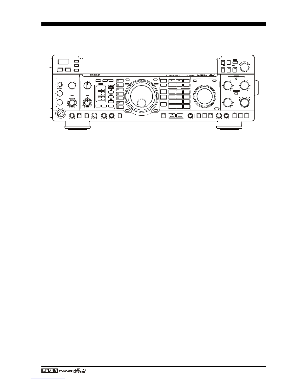
PLUG/CONNECTOR PINOUT DIAGRAMS
UP
+5V
DOWN
FAST
GND
PTT
MIC GND
MIC
+13.8 V
GND
N/A
+13.8 V
GND
N/A
+13V
TX GND
GND
BAND DATA A
BAND DATA B
BAND DATA C
BAND DATA D
LINEAR
VOICE IN
VOICE OUT
PTT
+9V
CNTL 1
CNTL 2
GND
NC
SERIAL OUT
SERIAL IN
N/A
GND
N/A
N/A
N/A
NC
DC IN
BAND DATA DVS-2
RTTYPACKET
REMOTE/EXT SPKR
AF OUT
PHONE
RCA PLUG
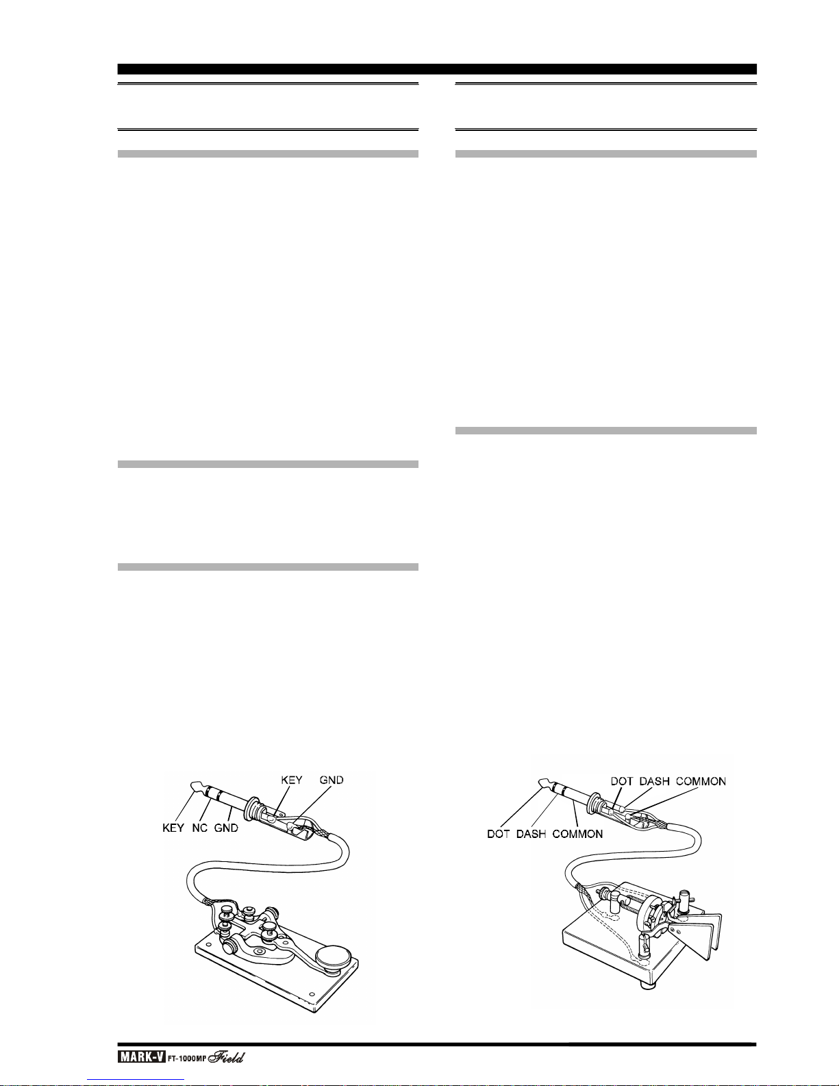
KEY
CAT
MIC
MAIN GND
SUB
DOT DASH COMMON
KEY COMMON
SIGNAL
GND
GND or
(−)
SIGNAL or
(+)
DATA IN
GND
PTT
DATA OUT
BUSY
SHIFT
RX OUT
PTT
GND
MAIN GND
SUB
(as viewed from rear panel)
(as viewed from rear panel)
(as viewed from rear panel)
(as viewed from rear panel)
(as viewed from rear panel)
(as viewed from rear panel)
(as viewed from front panel)
Internal Keyer
Straight Key
Do not use
2-conductor type plug
Use this jack for AFSK digita-mode connections Use this jack for FSK RTTY connections

Page 5OPERATING MANUAL
SUPPLIED ACCESSORIES
Hand Microphone MH-31B8 (depending on transceiver version) .........................................................................1
AC Power Cord (T9013282 for 100 - 120 V or T9013285 for 200 - 240 V) ..........................................................1
Spare Fuse (8-A [Q0000104] for 100 - 120 V or 4-A [Q0000103] for 200 - 240 V) ...............................................1
RCA Plug (P0090544) .......................................................................................................................................1
¼-inch 3-contact Plug (P0090008) .....................................................................................................................1
3.5 mm 2-contact Plug (P0090034)....................................................................................................................1
3.5 mm 3-contact Plug (P0091046)....................................................................................................................1
4-pin DIN Plug (P0091004)................................................................................................................................1
5-pin DIN Plug (P0091006)................................................................................................................................1
Operating Manual..............................................................................................................................................1
Warranty Card...................................................................................................................................................1
AVAILABLE OPTIONS
ACCESSORIES & OPTIONS
TCXO-6 HIGH-STABILITY MASTER REFERENCE OSCILLATOR
For special applications and environments where
extra frequency stability is essential, such as for longterm HF packet monitoring under wide temperature
variations, the TCXO-6 provides ±0.25-ppm stability
the master reference oscillator (after 1 min. @ 25 °C).
MD-100A8X DESK-TOP MICROPHONE
Designed especially to match the electrical and cosmetic features of the MARK-V
FT-1000MP
Field, the
MD-100A8X has a 600 Ohm impedance, and includes an
up/down scanning ring and a large PTT switch with latch.
MD-200A8X
ULTRA-HIGH-FIDELITY DESK-TOP MICROPHONE
Designed especially to match the electrical and cosmetic features of the MARK-V
FT-1000MP
Field, the
MD-200A8X includes a new-technology “Variable Side
Pressure Control” (VSPC), which allows precise ad-
justment of the microphone’s audio response without
resorting to “active” equalization circuits that can introduce distortion and/or degrade signal-to-noise ratio.
VL-1000 LINEAR AMPLIFIER
The VL-1000 is an all-solid-state linear amplifier
operating on the 160 through 6 meter amateur bands
(USA version: 160-15 meters) at a power output level
of 1000 Watts on CW and SSB (500 Watts on continuous data modes such as RTTY). The VL-1000 includes
a built-in antenna tuner with 240 memories for tuning
data, and microprocessor control of the tuning circuitry.
The VL-1000 features input jacks for two different
exciters, as well as four antenna jacks for connection
of antennas for different bands. Extensive self-test, system monitoring, and protection circuits are provided,
with status and tuning information being displayed on
a huge Liquid Crystal Display panel.
The companion VP-1000 AC Power Supply provides
the necessary voltages for the 48-Volt PA section of
the VL-1000.
FTV-1000 50 MHZ TRANSVERTER &
FRB-5 RELAY UNIT
The FTV-1000 is a high-performance, high-power 50-
54 MHz transverter compatible with the MARK-V
FT-
1000MP
Field. Providing excellent receiver performance
and up to 200 Watts of power output, the FTV-1000 is
specifically designed for the demanding requirements of
50 MHz DX operators. Among the leading-edge features
of the FTV-1000 is a Class-A operating bias selection for
the transmitter’s power amplifier stage; during Class-A
operation, power output is reduced to 50 Watts, and the
high bias current leads to an extraordinarily clean SSB
wave-form, with 5th-order intermodulation (IMD) typically
suppressed by at least 65 dB.
Besides this unit, you must also purchase the FP-
29 AC Power Supply and FRB-5 Relay Unit, available
from your Yaesu dealer.
The FRB-5 Relay Unit allows interconnection and
operation of the FTV-1000 with the MARK-V
FT-1000MP
Field Transceiver.
SP-8 LOUDSPEAKER WITH AUDIO FILTERS &
LL-7 PHONE PATCH OPTION
Selectable audio high- and low-pass filters together
with a large loudspeaker complement the superb audio characteristics of the MARK-V
FT-1000MP
Field
with your choice of 12 different audio filtering combinations. Two input terminals are provided for multiple
transceivers, with a front panel switch to select between
them. A (monaural) phone jack is provided on the front
panel to take advantage of the audio filters with headphones.
With the optional LL-7 Phone Patch Unit installed in
the SP-8, the MARK-V
FT-1000MP
Field can be patched
to the public telephone network. The LL-7 includes a
hybrid transformer circuit to assure proper impedance
matches, and front panel gain controls and level meter
to set proper audio levels on the telephone line.

Page 6 OPERATING MANUAL
ACCESSORIES & OPTIONS
YH-77STA LIGHTWEIGHT STEREO HEADPHONES
Dual samarium-cobalt transducers with sensitivity
of 103dB/mW (±2dB, @1 kHz, 35 Ohms) provide the
perfect match for the MARK-V
FT-1000MP
Field. During dual receive with the YH-77STA, one receiver can
be monitored in each ear, allowing easy separation of
the signals from the two receivers (or the audio can be
mixed, if desired).
DVS-2 DIGITAL VOICE RECORDER
Serving as either a continuous receiver recorder for
instant pushbutton playback, or microphone audio recorder for multiple on-air playback, the DVS-2 applies
the advantages of random-access solid-state digital
memory to serious communications. All data is stored
electronically, with no moving parts except your finger
and the pushbutton. More information is on page 81.
FH-1 REMOTE CONTROL KEYPAD
The FH-1 is a remote-control accessory designed
to enhance the operating flexibility of your MARK-V
FT-1000MP
Field. The FH-1 permits several remote
control features, which may be selected via Menu programming. More information is on page 76.
AVAILABLE OPTIONS
IF Crystal Filter Options
Five optional crystal filters may be installed in the
Main Receiver of the MARK-V
FT-1000MP
Field, and
one in the Sub Receiver.
Optional Main Receiver Filters
8.2 MHz (2nd IF)
YF-114SN: 2.0-kHz BW (for all modes except FM)
YF-114CN: 250-Hz BW (for all except AM & FM)
455 kHz (3rd IF)
YF-110SN: 2.0-kHz BW (for all modes except FM)
YF-115C Collins Mechanical Filter: 500-Hz BW (for CW
& RTTY)
YF-110CN: 250-Hz BW (for CW only)
Optional Sub Receiver Filter
455 kHz (2nd IF)
YF-115C: Collins Mechanical Filter 500-Hz BW (for CW
& RTTY)
Availability of accessories may vary: some accessories are supplied as standard per local regulations and
requirements, others may be unavailable in some regions. Check with your Yaesu dealer for additions to
the above list.
Page 7OPERATING MANUAL
SAFETY PRECAUTIONS
Before initiating the installation of your MARK-V
FT-
1000MP
Field transceiver, please take the time to re-
view the following safety guidelines.
POWER CONNECTIONS
The MARK-V
FT-1000MP
Field can be operated
from either AC or DC power sources.
When making AC connections to your house wiring, be certain that the voltage at the AC wall outlet
matches the voltage label on the rear panel of the transceiver.
If you are connecting to a 13.8 Volt DC source, use
the optional E-DC-20 DC Power Cable, and be certain
to observe the proper polarity when connecting to your
DC power supply. Connect the RED power cable lead
to the POSITIVE (+) terminal of the DC source, and
the BLACK power cable lead to the NEGATIVE (–)
terminal.
GROUND CONNECTIONS
The MARK-V
FT-1000MP
Field HF transceiver, like
any other HF communications apparatus, requires an
effective ground system for maximum electrical safety
and best communications effectiveness. A good ground
system can contribute to station efficiency in a number
of ways:
r It can minimize the possibility of electrical shock to
the operator.
r It can minimize RF currents flowing on the shield of
the coaxial cable and the chassis of the transceiver;
such currents may lead to radiation which can cause
interference to home entertainment devices or laboratory test equipment.
r It can minimize the possibility of erratic transceiver/
accessory operation caused by RF feedback and/
or improper current flow through logic devices.
An effective earth ground system make take several forms; for a more complete discussion, see an
appropriate RF engineering text. The information below is intended only as a guideline.
Typically, the ground connection consists of one or
more copper-clad steel rods, driven into the ground. If
multiple ground rods are used, they should be positioned in a “V” configuration, and bonded together at
the apex of the “V” which is nearest the station location. Use a heavy, braided cable (such as the discarded
shield from type RG-213 coaxial cable) and strong
cable clamps to secure the braided cable(s) to the
ground rods. Be sure to weatherproof the connections
to ensure many years of reliable service. Use the same
type of heavy, braided cable for the connections to the
station ground bus (described below).
Inside the station, a common ground bus consisting of a copper pipe of at least 25 mm (1”) diameter
should be used. An alternative station ground bus may
consist of a wide copper plate (single-sided circuit board
material is ideal) secured to the bottom of the operating desk. Grounding connections from individual devices such as transceivers, power supplies, and data
communications devices (TNCs, etc.) should be made
directly to the ground bus using a heavy, braided cable.
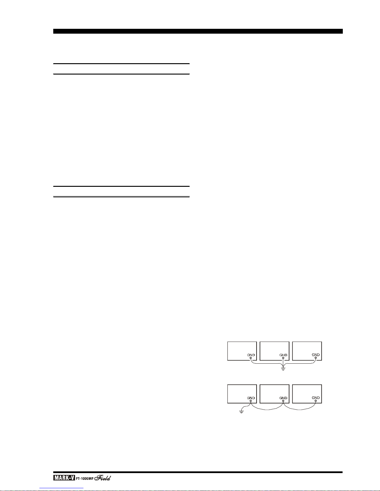
Do not make ground connections from one electrical device to another, and thence to the ground bus.
This so-called “Daisy-Chain” grounding technique may
nullify any attempt at effective radio frequency grounding. See the drawing below for examples of proper
grounding techniques.
Inspect the ground system – inside the station as
well as outside – on a regular basis so as to ensure
maximum performance and safety.
Besides following the above guidelines carefully,
note that household or industrial gas lines must never
be used in an attempt to establish an electrical ground.
Cold water pipes may, in some instances, help in the
grounding effort, but gas lines represent a significant
explosion hazard, and must never be used.
Linear
Amplifier
Power
Supply
Transceiver
Proper Ground Connection
Improper Ground Connection
Transceiver Linear
Amplifier
Power
Supply
"Daisy Chain"

Page 8 OPERATING MANUAL
ELECTRICAL SHOCK PREVENTION
Be certain that all station wiring is properly insulated so as to prevent short-circuits which could damage this transceiver and/or accessories connected to
it. Be sure to protect power cables from damage due
to abrasion by ensuring that they cannot be walked
upon nor crushed under rolling chairs, etc. Never route
power cables near sharp metallic edges which might
cut through protective insulation.
Never spill liquids into this transceiver, and do not
drop sharp metallic objects into the transceiver enclosure. Electrical shock may result when you attempt to
remove the object.
Unsupervised children should be kept away from
any electrical apparatus such as the MARK-V
FT-
1000MP
Field transceiver and its accessories.
ANTENNA P RECAUTIONS
Always install antennas such that they can never
come in contact with outdoor power lines in the event
of a catastrophic antenna support or power line support structure failure. An adequate safety margin is
usually provided by separating power lines from the
antenna and its support structure [1.5 times the height
of the support] plus [the length of any antenna or guy
wires attached to the support] plus [the height of the
power line support pole].
Ground the antenna support structure adequately,
so as to dissipate energy absorbed during a lightning
strike. Install appropriate lightning arrestors in the antenna lead-in and rotator cable (if used) according to
the arrestor’s instructions.
In the event of an approaching electrical storm, disconnect all antenna lead-in, rotator control, and power
cables completely from the station, but only if the
storm is not immediately in your area. Do not allow
disconnected cables to touch the case of your MARK-
V
FT-1000MP
Field transceiver or accessories, as lightning can easily jump from the cable to the circuitry of
your transceiver via the case, causing irreparable damage. If a lightning storm is in progress in your immediate area, do not attempt to disconnect the cables, as
you could be killed instantly should lightning strike your
antenna, tower, or a nearby power line.
If a vertical antenna is used, be certain that humans
and/or pets or farm animals are kept away both from
the radiating element (to prevent electrical shock and
RF exposure danger) and the ground system (in the
event of an electrical storm). The buried radials of a
ground-mounted vertical antenna can carry lethal voltages outward from the center of the antenna in the
event of a direct lightning strike.
RF FIELD EXPOSURE ADVISORY &
ELECTROMAGNETIC COMPATIBILITY
This transceiver is capable of power output in excess of 50 Watts, so customers in the United States
may be required to demonstrate compliance with Federal Communications Commission (FCC) regulations
concerning maximum permissible exposure to radio
frequency energy. Compliance is based on the actual
power output used, feedline loss, antenna type and
height, and other factors which can only be evaluated
as a system. Information regarding these regulations
may be available from your Dealer, your local radio
club, from the FCC directly (press releases and other
information can be found on the FCC’s site on the World
Wide Web at <http://www.fcc.gov>), or from the American Radio Relay League, Inc. (225 Main St., Newington
CT 06111 or <http://www.arrl.org>).
Remember to re-evaluate your station’s compliance
with these regulations during portable operations such
as Field Day or special-event stations.
Regarding electromagnetic compatibility: if this
transceiver is used with, or in the vicinity of, a computer or computer-driven accessories, you may need
to experiment with grounding and/or Radio Frequency
Interference (RFI) suppression devices (such as ferrite cores) to minimize interference to your communications caused by energy from the computer. Computer-generated RFI is usually a result of inadequate
shielding of the computer’s cabinet or I/O and peripheral connections. While computer equipment may
“comply” with RF emission standards, this does not
ensure that sensitive amateur radio receivers will not
experience interference from the device!
Be certain to use only shielded cables for TNC-toTransceiver connections. You may need to install AC
line filters on the power cord(s) of the suspected equipment, and decoupling ferrite toroidal chokes may be
required on interconnecting patch/data cables. As a last
resort, you can try installing additional shielding within
the computer’s case, using appropriate conductive
mesh or conductive shielding tape. Especially check
“RF holes” where plastic is used for cabinet front panels.
For further information, consult amateur radio reference guides and publications relating to RFI suppression techniques.
SAFETY PRECAUTIONS

Page 9OPERATING MANUAL
PRELIMINARY INSPECTION
Inspect the transceiver upon opening the packing
carton. Check that all controls and switches work freely,
and inspect the cabinet for any damage. Ensure the
accessory fuses and plugs pictured on page 4 are included. If any damage is found, document it completely,
and contact the shipping company (or dealer, if you
purchased it over-the-counter) right away. Save the
packing materials in case you need to return the set
for service. If you have purchased optional internal
accessories separately, install them as described on
page 112.
POWER CONNECTIONS
Before connecting AC power, check the label on
the rear panel which indicates the AC mains voltage
for which your transceiver is currently set. If the voltage on this label does not match your AC mains voltage, a switch on the internal power supply in the transceiver must be moved, and the fuse must be changed
(U.S.A. users only). See page 116 for more information and details.
After making certain the AC voltage for which the
transceiver is set matches your mains voltage, and that
the correct fuse is installed in the fuse holder, connect
the supplied AC power cord between the 3-pin ~AC IN
jack on the rear panel and the AC wall outlet.
The MARK-V
FT-1000MP
Field can also be operated from 13.8 Volts DC, negative ground, with any
well-regulated DC source being capable of providing
22 Amperes of continuous current.
If you are connecting to a DC source, use the optional E-DC-20 DC Power Cable (with 25-A fuse). Connect the RED power cable lead to the POSITIVE (+)
terminal of the DC source, and the BLACK power cable
lead to the NEGATIVE (–) terminal, then connect the
DC plug from the E-DC-20 to the ...– DC IN jack on the
rear panel.
Warning: Our warranty does not cover damage
caused by improper supply voltage nor use of an
improper fuse.
NOTE
If you have both AC and DC power sources connected at the same time, the MARK-V
FT-1000MP
Field will automatically select the external DC sup-
ply as its power source.
GENERAL SETUP
TRANSCEIVER LOCATION
To assure long life of the components, a primary
consideration in setting up the MARK-V
FT-1000MP
Field is providing for adequate ventilation around the
cabinet. The cooling system of the MARK-V
FT-1000MP
Field must be free to draw cool air in at the lower rear
of the transceiver, and to expel warm air out of the
upper rear panel. Do not place the transceiver on top
of another heat-generating device such as a linear
amplifier, and do not place equipment, books or papers on top of the transceiver. Also, provide a few centimeters of space on either side of the transceiver, if
possible. Avoid heating vents and window locations that
could expose the transceiver to excessive direct sunlight, especially in hot climates.
GROUNDING
For protection from electrical shock, and to ensure
proper performance, connect the GND terminal on the
rear panel to a good earth ground, using a heavy
braided cable of the shortest length possible. All other
station equipment should be connected to the same
grounding cable, as close together as practical. If you
use a computer with or near the MARK-V
FT-1000MP
Field, you may need to experiment with ground wiring
to suppress computer noise in the receiver, and ground
loops during transmission.
Page 10 OPERATING MANUAL
ANTENNA CONSIDERATIONS
Loss figures are approximate; consult cable manufacturers’ catalogs for complete specifications.
Loss figures can increase significantly if high SWR is
present on the transmission line.
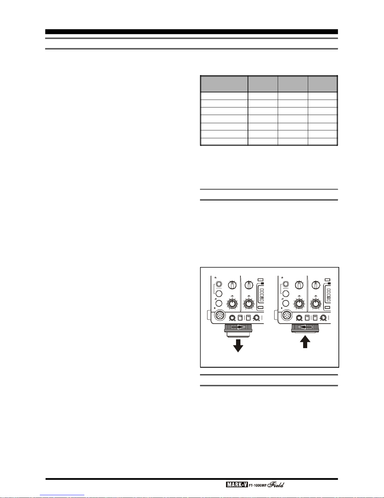
ADJUSTING THE FRONT FEET
The two front feet of the MARK-V
FT-1000MP
Field
can be set in either of two positions. By turning the
knurled ring around a (retracted) foot clockwise, the
middle of the foot will extend about one centimeter.
Turn the ring as far as it will go (about ¼-turn) to lock
the extended foot in place. To retract an extended foot,
turn the knurled ring counterclockwise ¼-turn while
pressing on the center of the foot.
GENERAL SETUP
MEMORY BACKUP
The memory BACKUP switch on the rear panel is
turned on at the factory, allowing VFO and memory
data to be retained while power is off. Backup current
is miniscule, so it is not necessary to turn the BACKUP
switch off unless the transceiver is to be stored for an
extended period.
After five or more years of operation the transceiver
may fail to retain memories, at which time the lithium
battery should be replaced. Contact your dealer for
replacement of the battery; for instructions on how to
do so yourself, see page 114.
Loss in dB per 30m (100 feet)
for Selected 50 W Coaxial Cables
(
Assumes 50 W Input/Output Terminations
)
(
To Retract
)(
To Extend
)
The MARK-V
FT-1000MP
Field is designed for use
with any antenna system providing a 50 W resistive
impedance at the desired operating frequency. While
minor excursions from the 50 W specification are of no
consequence, the transceiver’s Automatic Antenna
Tuner may not be able to reduce the impedance mismatch to an acceptable value if the Standing Wave
Ratio (SWR) present at the Antenna jack is greater
than 3:1. Among the undesirable consequences that
high SWR may produce are:
r The transceiver’s power amplifier protection circuitry
will reduce power if the Automatic Antenna Tuner is
unsuccessful in reducing the SWR.
r Even if the Automatic Antenna Tuner successfully
normalizes the impedance presented to the radio,
feedline losses will escalate rapidly with increasing
SWR at the higher operating frequencies, especially
28 MHz.
r Although high SWR itself does not cause feedline
radiation, the sudden onset of high SWR may well
indicate a mechanical failure in a matching device,
leading to an electrical condition which may cause
excessive feedline radiation, which can cause interference to nearby home-entertainment devices.
Every effort should, therefore, be made to ensure
that the impedance of the antenna system utilized with
the MARK-V
FT-1000MP
Field be as close as possible
to the specified 50 W value.
Any antenna to be used with the MARK-V
FT-
1000MP
Field must, ultimately, be fed with 50 W co-
axial cable. Therefore, when using a “balanced” antenna such as a dipole, remember that a balun or other
matching/balancing device must be used so as to ensure proper antenna performance.
The same precautions apply to any additional (receive-only) antennas connected to the RX ANT jack; if
your receive-only antennas do not have an impedance
near 50 W at the operating frequency, you may need to
install an external antenna tuner to obtain optimum
performance.
Use high-quality 50 W coaxial cable for the lead-in
to your MARK-V
FT-1000MP
Field transceiver. All efforts at providing an efficient antenna system will be
wasted if poor quality, lossy coaxial cable is used.
Losses in coaxial lines increase as the frequency increases, so a coaxial line with only 0.5 dB of loss at 7
MHz may have 2 dB of loss at 28 MHz. For reference,
the chart in the next column shows approximate loss
figures for typically-available coaxial cables frequently
used in amateur radio installations.
Cable Type
RG-58A
RG-58 Foam
RG-8X
RG-8A, RG-213
RG-8 Foam
Belden® 9913
RG-17A
Loss:
2 MHz
0.55
0.54
0.39
0.27
0.22
0.18
0.88
Loss:
15 MHz
1.75
1.50
1.07
0.85
0.65
0.50
0.30
Loss:
28 MHz
2.60
2.00
1.85
1.25
0.88
0.69
0.46
KEY
MIC
A
B
PHONES
AGC
MIC
AF
GAINRFGAIN
PROC
FAST 0
6
12
18
dB( )
OFF SLOW
AUTO
ATT
240
120
60
IPO
OFF
APF
APF
RF PWR MONI SUB AFPROC
ED
KEY
MICAB
PHONES
AGC
MIC
AF
GAINRFGAIN
PROC
FAST 0
6
12
18
dB
( )
OFF SLOW
AUTO
ATT
240
12060IPO
OFF
APF
APF
RF PWR MONI
SUB AF
PROC
ED
Page 11OPERATING MANUAL
LINEAR AMPLIFIER INTERFACING
ACCESSORY INSTALLATION
The MARK-V
FT-1000MP
Field can be used with
the optional Yaesu FL-7000 or VL-1000 Linear Amplifier, providing automatic band switching via digital band
data output from the BAND DATA jack on the rear panel
of the transceiver. Most other amplifiers can be adapted
to operate with the MARK-V
FT-1000MP
Field; however, the main points to be concerned with are the
switching requirements of the amplifier, and if QSK (full
break-in) operation is desired. The linear amplifier Tx/
Rx switching capability of the MARK-V
FT-1000MP
Field is described in the table below.
OPERATION WITH QSK AMPLIFIERS
Connect the RF output from the transceiver ANT
jack (A or B) to the RF input jack of the linear. Connect
the ALC output from the linear to the EXT ALC jack on
the rear of the transceiver (see the “About ALC” discussion below). After making the RF and Tx/Rx switching connections described below, you may need to
adjust the ALC output level of the linear so that it is not
overdriven by the MARK-V
FT-1000MP
Field. Your
linear’s manual should describe how to do this.
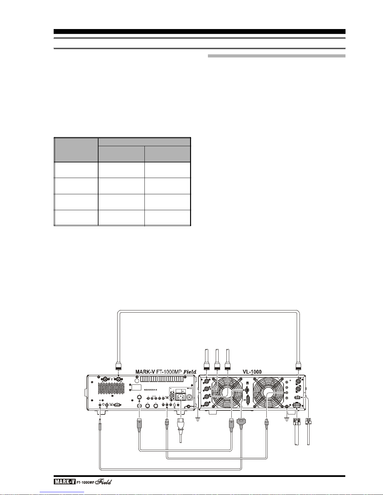
If using a VL-1000, connect the BAND DATA Cable
(supplied with the VL-1000) from the transceiver BAND
DATA jack to the amplifier BAND-DATA 1 jack; this will
provide automatic band selection for the linear, as well
as QSK Tx/Rx switching control. You may also connect a user-constructed control cable (refer to VL-1000
manual for details) from the transceiver REMOTE jack
to the amplifier BAND-DATA 2 jack to provide automatic amplifier tune-up for the linear using the MARK-
V
FT-1000MP
Field. Press the VL-1000’s front panel
ATT switch to disable the 3 dB input RF power attenu-
ator.
Operation
Parameter
DC Switching
Voltage
DC Swiching
Current
AC Switching
Voltage
AC Swiching
Current
QSK
Relay Disabled
< 40VDC
< 150 mA
–
–
Non-QSK
Relay Enabled
< 60 VDC
< 200 mA
< 100 VAC
< 500 mA
REMOTE
B AANT
KEY BACKUP
LIN
CAT
DVS-2
BAND DATA
+13.8V TRV TX GNDRX ANT
PACKET RTTY PTT
EXT
ALC
EXT
SPKR
PATCH AF OUT
GND
OFF
OFF
IN OUT
CW
SIDETONE
ON
ACC
ON
OUTPUT
DC 13.8V
200 mA
INPUT
DC 13.8V
20 A
INPUT
AC 100-120V ~
50-60Hz 6A
FUSE
T8A
DC IN ~ AC IN
ANT 1
ANT 2
ANT 3
ANT 4
REMOTE
ON
OFF
BAND DATA 1
BAND DATA 2
GND
ALC 2
ALC 1
PTT 2
PTT 1
INPUT 1
INPUT 2
CONTROL
DC48V IN
A
NT-
AA
N
T
1
H
F
Ver
t
ical Ante
nnaHF
Di
pole
A
n
ten
naH
F
Beam
A
n
t
e
nnaAN
T
2
A
N
T
3
INPUT
1EX
T
A
LCREM
OTE
B
A
ND
D
ATA
B
AND
-
D
ATA
1B
A
N
D
-
DATA
2
GNDGN
DDC 48V I
N
~AC
INCON
T
R
O
L
A
L
C 1
ALC CABLE (Supplied w/VL-1000)
BAND DATA CABLE (Supplied w/VL-1000)
ANTENNA CABLE
CONTROL CABLE (See VL-1000 Operating Manual for details)
V
P-1000V
P-100
0
Ü
Ü
Page 12 OPERATING MANUAL
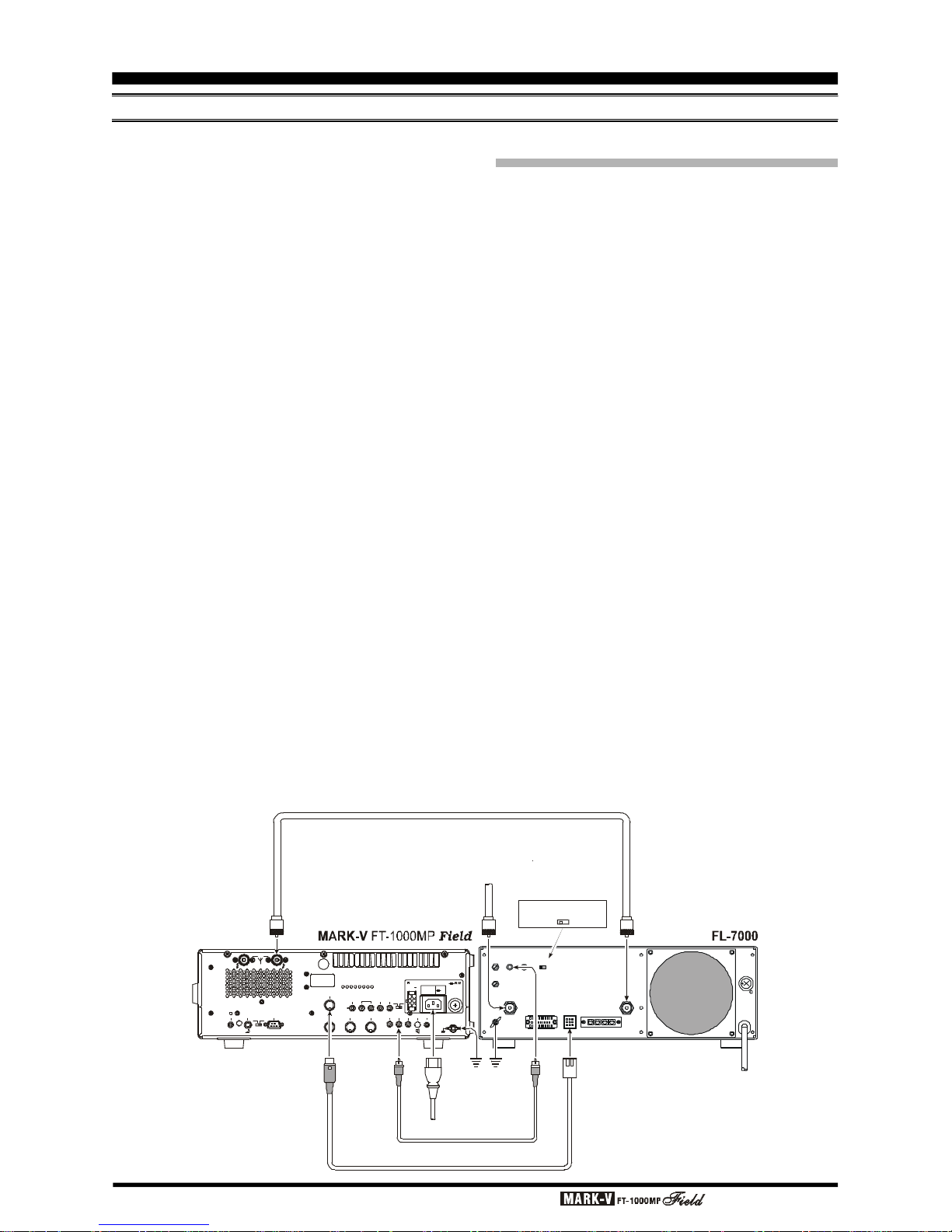
If using an FL-7000, connect optional cable E-767
(P/N D4000019) from the transceiver BAND DATA jack
to the amplifier ACC-2 jack. This provides automatic
band selection for the linear, as well as QSK Tx/Rx
switching control. Turn on the FL-7000 rear panel ATT
switch to disable the 3 dB input RF power attenuator.
If using another manufacturer’s QSK linear, and if
its switching circuitry consumes less than 150 mA of
DC voltage below 40 V, you can connect the Tx/Rx
switching line for the linear to pin 2 (“TX GND”) of the
BAND DATA jack (use pin 3 for ground), and the linear’s
exciter-enable output to pin 8 (“TX INHIBIT”) of the
BAND DATA jack. This line must be switched to ground
to enable transmission once the linear is ready for excitation from the MARK-V
FT-1000MP
Field. If your
QSK linear sinks more than 100 mA or uses more than
15 V for T/R relay switching, you will have to provide a
suitable external interface transistor, controlled by pin
2. Be certain to make provision for suitable reduction
of the drive power from the MARK-V
FT-1000MP
Field,
so as not to damage your amplifier.
LINEAR AMPLIFIER INTERFACING
OPERATION WITH NON-QSK AMPLIFIERS
(FL-2100 SERIES OR OTHERS)
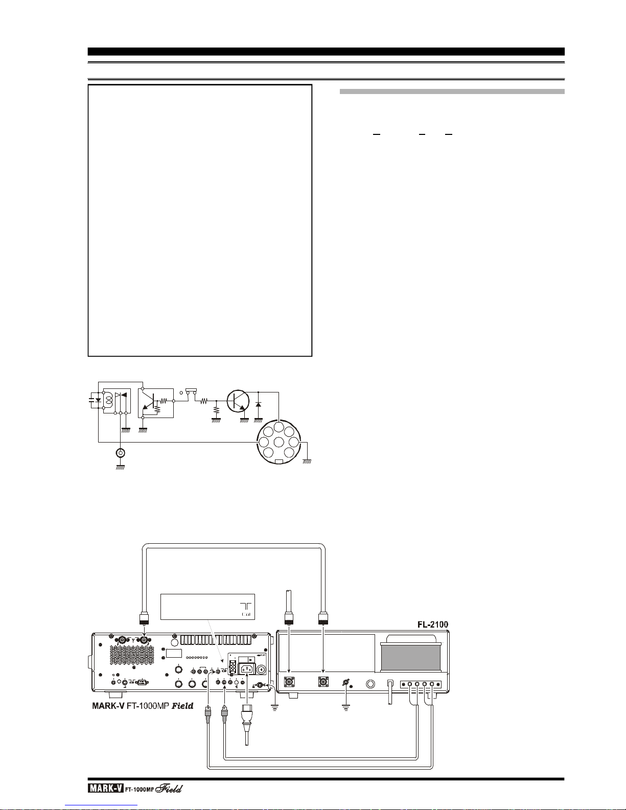
The TX GND jack on the transceiver rear panel is
connected to an internal relay, for non-QSK T/R switching of linear amplifiers that use AC switching voltage,
or DC voltage greater than +15 V, negative DC voltage
of any kind (such as the Heath® SB-220/SB-221 models), or if they are required to sink more than 100 mA
for T/R switching. A schematic diagram of the relay
circuit is provided below. If not using your linear amplifier in a full break-in environment, the use of this relay
for amplifier switching is highly recommended.
This relay comes disabled (rear-panel LIN set to
“OFF”) to avoid the clicking sound when the transceiver
is used alone or with a QSK linear. To enable the relay
for non-QSK linears that exceed the above T/R switching requirements, you will need to move the LIN switch,
located in the hole near the center of the rear panel, to
its right position (see the drawing). Use a thin, insulated, sharp object to move the switch. Then connect
the center contact of the TX GND jack to the positive
relay-control line to your linear, and the outer contact
to the “common” line or the linear’s chassis ground.
Refer to the diagram at the next page; in this example,
a older non-QSK amplifier (FL-2100B) is shown.
With the relay now enabled, the MARK-V
FT-1000MP
Field can support non-QSK linear T/R switching voltages up to 100 VAC @ 500 mA, or DC voltage up to 60
V @ 200 mA, or closed-circuit current up to 1 A with
DC voltage up to 30 V.
ACCESSORY INSTALLATION
REMOTE
B AANT
KEY BACKUP
LIN
CAT
DVS-2
BAND DATA
+13.8V TRV TX GNDRX ANT
PACKET RTTY PTT
EXT
ALC
EXT
SPKR
PATCH AF OUT
GND
OFF
OFF
IN
OUT
CW
SIDETONE
ON
ACC
ON
OUTPUT
DC 13.8V
200 mA
INPUT
DC 13.8V
20 A
INPUT
AC 100-120V ~
50-60Hz 6A
FUSE
T8A
DC IN ~ AC IN
SSB ALC
RTTY ALC
GND
ANT INPUT
ACC-1 ACC-2 REMOTE
A B C GND
ALC PTT
OFF ATT
A
NT- AAN
T
1
H
F
A
n
t
enn
a
INPUTEX
T
A
LCE
X
T
A
LCG
N
D
~
A
C I
N
OFF
ATT
Turn "” the switch
OFFATT
A
CC-
2
BAN
D DAT
A
ALC CABLE (Supplied w/FL-7000)
ANTENNA CABLE (Supplied w/FL-7000)
E-767 BAND DATA CABLE (Option: P/N D4000019)
Page 13OPERATING MANUAL
REMOTE
B AANT
KEY BACKUP
LIN
CAT
DVS-2
BAND DATA
+13.8V TRV TX GNDRX ANT
PACKET RTTY PTT
EXT
ALC
EXT
SPKR
PATCH AF OUT
GND
OFF
OFF
IN OUT
CW
SIDETONE
ON
ACC
ON
OUTPUT
DC 13.8V
200 mA
INPUT
DC 13.8V
20 A
INPUT
AC 100-120V ~
50-60Hz 6A
FUSE
T8A
DC IN ~ AC IN
EERY
ALCACFUSE
GND
RF IN
RF OUT
A
N
T-
AAN
T
1
H
F
Antenn
a
INP
U
T
1EX
T
A
L
C
TX
GND
GND
GND
~
AC
I
N
OFF
LIN
ON
When using jack,
move switch to the "" position
TX GND
LINON
Caution - Please Read!!
The MARK-V
FT-1000MP
Field is designed for use
with the FL-7000/VL-1000 when QSK operation
with a linear amplifier is desired. If you are using a
different amplifier, do not attempt QSK operation
with the linear if its switching circuitry requires that
the MARK-V
FT-1000MP
Field’s relay be enabled.
Using pins 2 and 8 of the BAND DATA jack for
other amplifiers will not work unless the control line
signals are carefully matched, and damage may
result otherwise.
Your transceiver’s warranty does not cover damage resulting from improper connections to this
jack, so if you are not sure of the linear amplifier’s
break-in capabilities or switching requirements, the
safest approach is to enable the relay, use the TX
GND jack (after setting the LIN switch to the “ON”
position) and resort to non-QSK operation. This will
help prevent possible damage to the amplifier or
transceiver.
LINEAR AMPLIFIER INTERFACING
ABOUT ALC
The MARK-V
FT-1000MP
Field provides an external ALC jack on the rear panel (RCA-type jack) for
input of Automatic Level Control voltage from a linear
amplifier.
ALC voltage is used to provide dynamic control of
the output of the transceiver, so as not to provide more
drive than is needed for full amplifier output. The ALC
control voltage range is 0 to –4 V DC, with the voltage
going more negative as the amplifier’s drive requirements are approaching fulfillment.
The MARK-V
FT-1000MP
Field’s ALC system is
very typical of designs in the amateur radio industry,
and consequently is compatible with many manufactured and home-built amplifiers. However, ALC voltage may be generated by an amplifier in a manner
incompatible with efficient ALC operation in the MARK-
V
FT-1000MP
Field, and it is important that you recognize the differences in amplifier ALC circuits before proceeding with ALC line connection.
r ALC circuits which detect Power Output from the
amplifier, and generate negative-going ALC control
voltage when maximum output power has been realized, will generally work properly with the MARK-
V
FT-1000MP
Field.
The exact amount of ALC voltage fed to the MARK-
V
FT-1000MP
Field can usually be adjusted via a
potentiometer on the rear panel of the amplifier.
r ALC circuits which detect Amplifier Tube Grid Cur-
rent, and generate ALC voltage when excessive
grid current is present, may not work well with the
MARK-V
FT-1000MP
Field and other similar transceivers, as the ALC voltage may be generated because of amplifier mis-tuning not related to an excessive-drive condition. With amplifiers deriving
their ALC voltage in this manner, we recommend
that you not connect the ALC line, and rather let the
amplifier’s protection circuitry manage its ALC requirements internally.
ACCESSORY INSTALLATION
1478526
3
TX GND
BAND DATA
Jack
LIN Switch
OFF ON
Q1008
40V DC, 150 mA max.
Page 14 OPERATING MANUAL
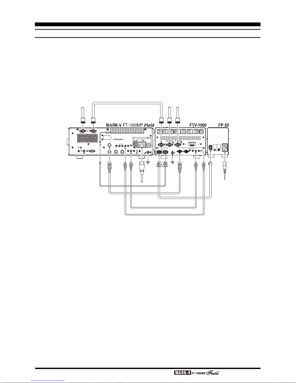
TRANSVERTER OPERATION
The MARK-V
FT-1000MP
Field can be used with
the optional Yaesu FTV-1000 50 MHz Transverter, providing excellent receiver performance and up to 200
Watts of power output.
Besides the FTV-1000, you must purchase the FP-
29 AC Power Supply and install the FRB-5 Relay Unit
into your MARK-V
FT-1000MP
Field.
ACCESSORY INSTALLATION
A typical FTV-1000 setup is shown below. Installation information for the FRB-5 is provided in the FRB-
5 Installation Manual, while connection and operation
instructions for the FTV-1000 may be found in that
model’s Operating Manual.
REMOTE
B AANT
KEY BACKUP
LIN
CAT
DVS-2
BAND DATA
+13.8V TRV TX GNDRX ANT
PACKET RTTY PTT
EXT
ALC
EXT
SPKR
PATCH AF OUT
GND
OFF
OFF
IN OUT
CW
SIDETONE
ON
ACC
ON
OUTPUT
DC 13.8V
200 mA
INPUT
DC 13.8V
20 A
INPUT
AC 100-120V ~
50-60Hz 6A
FUSE
T8A
DC IN ~ AC IN
BAND DATA
LIN BAND DATA
ALC
TX IN
ATT
ONOFF
ANT
NORALT
TRANSCEIVER
GND
FROM FP-29
TO MARK-V FT-1000MP
DC 30V 15A DC 30V 15A
DC 13.8V 3A DC 13.8V 3A
INPUT: OUTPUT:
4909959000000
FTV-1000
A
NT-
AA
NT- BAN
T
NORA
N
T
A
LT(
G
R
A
Y
)
E
X
T
ALC(
BLA
CK) TRVBAND
DAT
AAC
C
(GR
A
Y
) AL
C(B
LACK)
TX I
N
BAND
DATAGNDGND~
AC
I
NINPUTOUTPUTDC POWE
R I
NDC P
OWER OU
T
DC POWER CABLE
(Supplied w/FP-29)
ANTENNA CABLE (Supplied w/FTV-1000)
BAND DATA CABLE
(Supplied w/FTV-1000)
CONNECTION CABLE B
(Supplied w/FRB-5A)
TRV CABLE (Supplied w/FTV-1000)
ALC CABLE (Supplied w/FTV-1000)
H
F
A
n
t
e
n
n
a
5
0
M
H
z
A
n
t
e
n
n
a
5
0
M
H
z
A
n
t
e
n
n
a
T
RAN
S
CEI
VER
OUTPUT
INPUT
DC 30V
DC 13.8V
AC 200-240V~
50-60 Hz 5A
15A
3A
Page 15OPERATING MANUAL
ACCESSORY INSTALLATION
DIGITAL MODEM (TNC, WEATHERFAX, ETC.) INTERFACING
The MARK-V
FT-1000MP
Field offers special features for digital modes, such as a built-in digitally-synthesized AFSK generator for RTTY and AMTOR terminal units, IF bandwidth optimization and automatic
display offsets, and an 18-ms transmit-to-receive turnaround time.
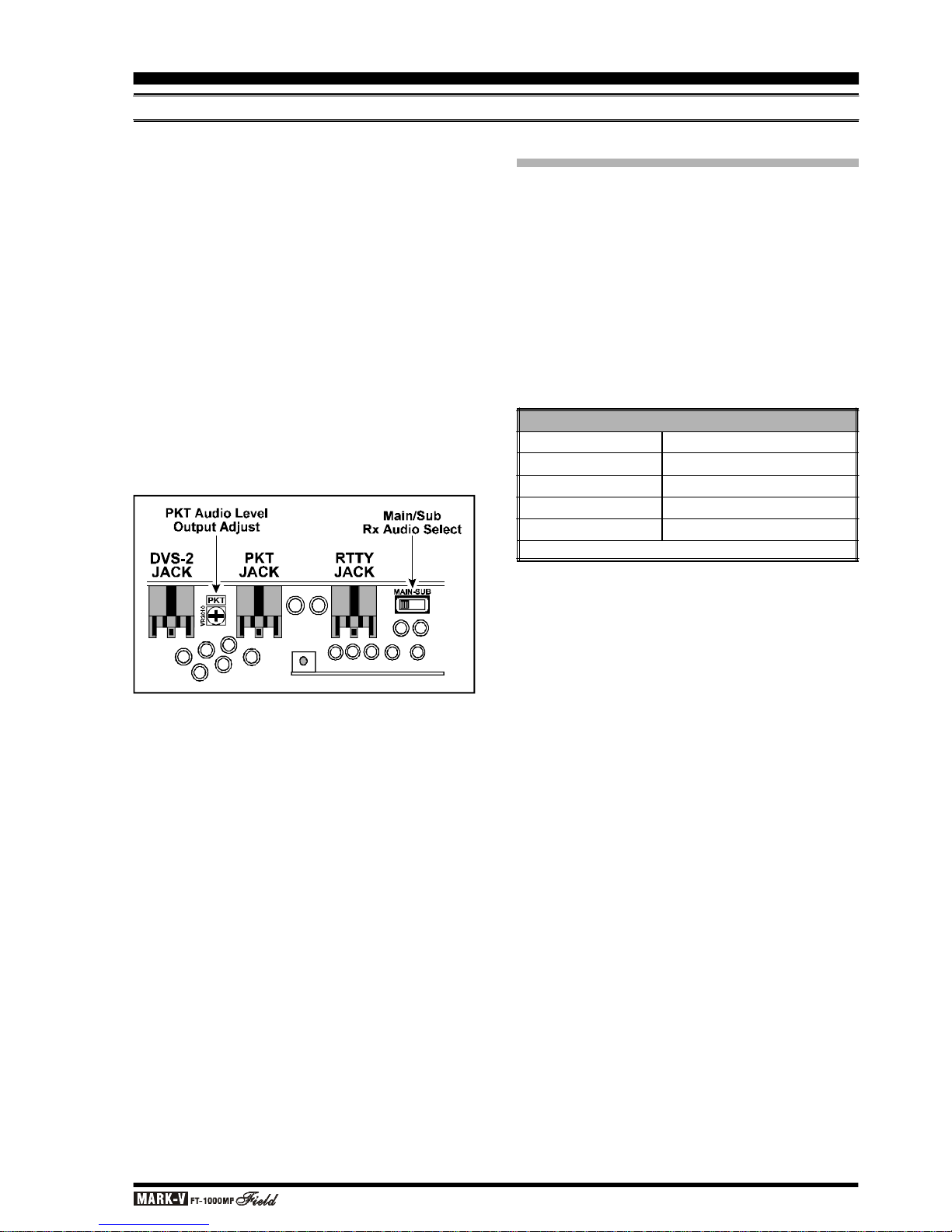
Low-level Main Receiver audio output is provided
from the rear-panel RTTY and PKT jacks, and is unaffected by front panel volume control settings. If you
prefer to use Sub Receiver audio for TNC input, switch
S3001 (located on the AF UNIT circuit board, inside
the transceiver, between the DVS-2 and PKT connectors) can be moved from the MAIN to the SUB position.
Audio level is 100 mV from both jacks. The RTTY
level is fixed; however, PKT audio level can be adjusted
by potentiometer VR3010. In many cases, it is easier
to perform level adjustments at the TNC.
DIGITAL MODES WITH A TNC
OR COMPUTER SOUND CARD
(
PSK-31
)
The explosion of new digital modes of amateur communication means that you will want to make connections to your TNC and/or computer as “standardized”
as possible. Generally, this will mean that you will want
to connect your transceiver in an “AFSK” environment.
On the MARK-V
FT-1000MP
Field, the PACKET jack
is the “AFSK” connection port, while the RTTY jack is
an “FSK” connection port. In the AFSK mode, the TNC
or computer generates the data signal as a set of audio tones, while the FSK mode uses a closure to ground
(in the TNC or terminal unit) to cause the transceiver
to generate the “mark” and “space” tones.
PACKET TONE INFORMATION
TNC Tone Pair
1070/1270 Hz
1600/1800 Hz
2025/2225 Hz
ø
2110/2310 Hz
Tone Center Frequency
1170 Hz
1700 Hz
2125 Hz
ø
2210 Hz
ø indicates default setting (used by normal convention)
Page 16 OPERATING MANUAL
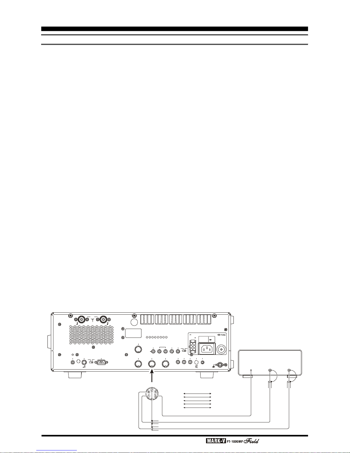
Construct a patch cable or cables to make the necessary connections between your TNC and the appropriate rear panel jack(s) (RTTY for FSK, PACKET for
AFSK). Refer to the pin-out diagram below, and the
wiring instructions included with your TNC. A description of the PACKET jack’s individual pins follows:
Pin 1 (DATA IN) - Connect this pin to your TNC’s
“AFSK Out” or “Mic Audio” output line. The optimum
input level is 30 mV rms, and the input impedance is 3
kW. Your TNC’s audio output level potentiometer will
allow you to set the level to the optimum value. This
pin may be used either for 300 baud SSB-mode digital
operation or for 1200-baud FM packet. The bandwidth
and frequency response are not, however, suitable for
9600 baud operation.
Pin 2 (Ground) - Connect this to the shield(s) of
the cable(s) used for connections between the TNC
and the MARK-V
FT-1000MP
Field.
Pin 3 (PTT) - Connect this pin to the PTT line from
the TNC. This pin, when grounded by the TNC, places
the MARK-V
FT-1000MP
Field into the Transmit con-
dition.
Pin 4 (DATA Out) - Connect this pin to your TNC’s
“RX Audio” input line. This is a constant-level (100 mV
rms @ 600 W) audio output line which is not affected
by the position of the front-panel
AF GAIN control.
Pin 5 (BUSY) - This is a “Squelch Status” pin not
generally required for digital mode operation. This pin
is held at +5V when the squelch is open, and is
grounded when the receiver is muted by the squelch
(“no-signal” condition).
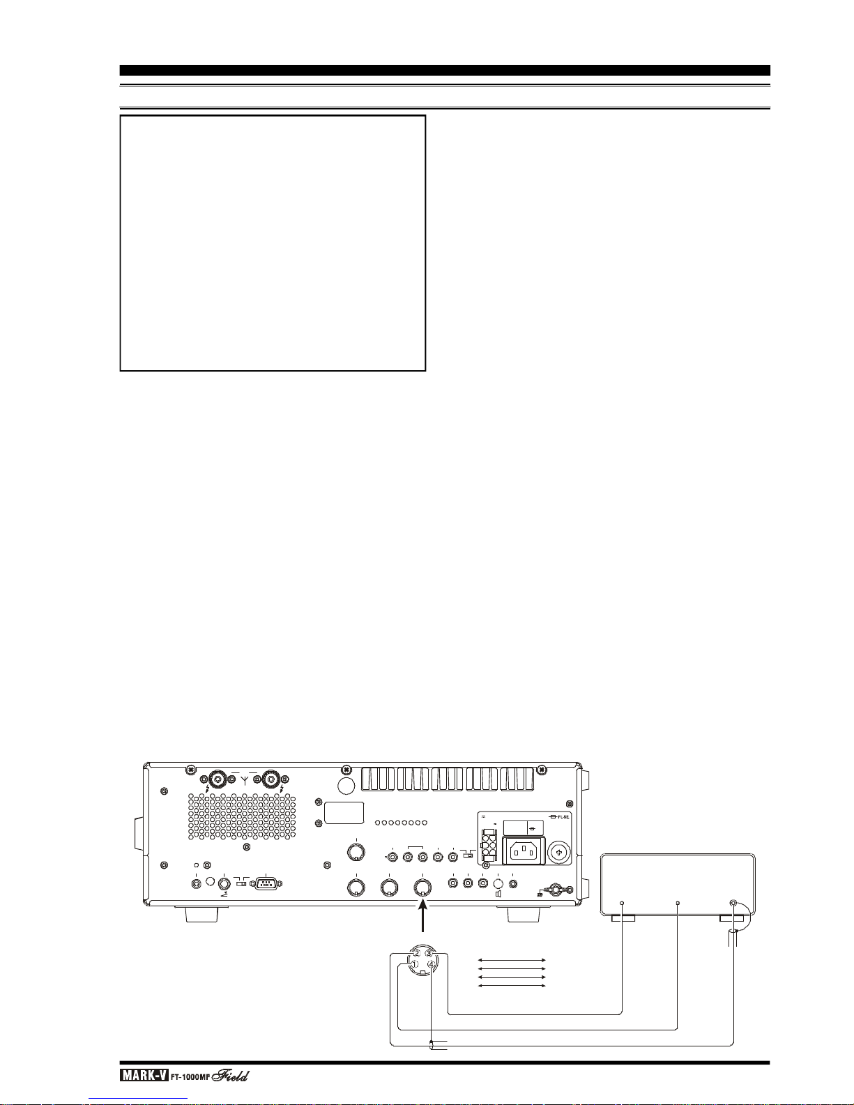
For FSK operation using the RTTY jack, the fol-
lowing are the pin connections required:
Pin 1 (SHIFT) - Connect this pin to your TNC or
terminal unit’s “FSK Key” port. Closing and opening of
this line to ground causes mark/space keying.
Pin 2 (RX AF OUT) - Same as “DATA OUT” on
PACKET jack.
Pin 3 (PTT) - Same as “PTT” on PACKET jack.
Pin 4 (GND) - Same as “GND” on PACKET jack.
For operation on PSK31, connect your computer's
sound card to the PACKET jack (for “PKT” mode operation) or the MIC and EXT SP jacks (for “SSB” mode
operation). Also, use menu selection 8-6 to configure
the “User” mode (see page 110) for PSK31 operation.
For most operation, you will want to use the PS31U (for PKT mode) or PS31-SU (for USB mode) options under “East Set;” while BPSK operation is not
sideband-sensitive, QPSK operation, by convention,
utilizes USB-side injection.
The “User” mode is accessed, during operation, by
pressing and holding in for ½ second the [PKT] mode
switch.
ACCESSORY INSTALLATION
DIGITAL MODEM (TNC, WEATHERFAX, ETC.) INTERFACING
MARK-V
FT-1000MP
Field
TNC
REMOTE
B AANT
KEY BACKUP
LIN
CAT
DVS-2
BAND DATA
+13.8V TRV TX GNDRX ANT
PACKET RTTY PTT
EXT
ALC
EXT
SPKR
PATCH AF OUT
GND
OFF
OFF
IN OUT
CW
SIDETONE
ON
ACC
ON
OUTPUT
DC 13.8V
200 mA
INPUT
DC 13.8V
20 A
INPUT
AC 100-120V ~
50-60Hz 6A
FUSE
T8A
DC IN
~ AC IN
DATA
OUTPTT
DATA
IN
PACKET
PACKET JACK
TNC
Pin 1
Pin 2
Pin 3
Pin 4
Pin 5
DATA OUT
GND
PTT
DATA IN
(SQL Control)
Page 17OPERATING MANUAL
ACCESSORY INSTALLATION
DIGITAL MODEM (TNC, WEATHERFAX, ETC.) INTERFACING
TNC
CAUTION!!
The MARK-V
FT-1000MP
Field cooling system is
designed to handle continuous duty transmission
at 100 watts output. However, for continuous-duty
digital modes like RTTY, we recommend limiting
your transmissions to 3 minutes or less, with at
least 3 minutes receive in between transmissions.
Place your hand on the transceiver occasionally to
ensure that it’s not getting too hot, and try to keep
power output at 50 watts or less.
You can limit the maximum RF power output to 25
watts via programming, by recalling menu selection
4-0 and choosing reduced power output.
MARK-V
FT-1000MP
Field
REMOTE
B AANT
KEY BACKUP
LIN
CAT
DVS-2
BAND DATA
+13.8V TRV TX GNDRX ANT
PACKET RTTY PTT
EXT
ALC
EXT
SPKR
PATCH AF OUT
GND
OFF
OFF
IN OUT
CW
SIDETONE
ON
ACC
ON
OUTPUT
DC 13.8V
200 mA
INPUT
DC 13.8V
20 A
INPUT
AC 100-120V ~
50-60Hz 6A
FUSE
T8A
DC IN
~ AC IN
FSK OUT
PTT AF IN
RTTY
RTTY JACK
RTTY Machine
Pin 1
Pin 2
Pin 3
Pin 4
FSK OUT
AF IN
PTT
GND

Page 18 OPERATING MANUAL
NOTE: COMPUTER-GENERATED RFI
When using a TNC connected to your transceiver,
or even having a PC located in the shack, the possibility exists that you may experience computer-generated
RFI (Radio Frequency Interference).
The CPU in a personal computer operates with a
crystal-controlled oscillator (clock), which may generate harmonics or other spurious signals. In addition,
high-speed digital data switching uses square waves,
which produce odd-order harmonic frequencies.
Computer-generated RFI may appear at seemingly
random frequencies (usually right where a rare DX station is calling CQ!) throughout the range of your transceiver, and may sound like constant ticking or buzzing
that may change as you type or work within a program.
Severe RFI may have S-meter indications as much
greater than S-9, making copy of voice signals difficult
and data signals virtually impossible.
Computer-generated RFI is usually a result of inadequate shielding of the PC’s cabinet or I/O and peripheral connections. While computer equipment may
comply with RF emission approval standards, this does
not ensure that sensitive amateur radio receivers will
not experience RFI from the device.
There are a few steps you can take to reduce or
eliminate computer-generated RFI. The first step is to
ensure that only shielded cables are used for TNC-totransceiver connections, carefully check RF ground
connections and re-orient your station equipment in
relation to the computer. Try moving your PC and peripherals slightly and see if it has any affect on the RFI,
in some cases, this alone may be enough to correct
the problem.
If not, several additional steps to try include installing AC line filters on the power cord(s) of the suspected
equipment and inserting decoupling ferrite toroidal
chokes on interconnecting patch/data cables and
smaller ferrite beads on single wires.
As a last resort, you can try installing additional
shielding within the PC case, using appropriate conductive mesh/screening or conductive tape. Especially
check RF “holes” where plastic is used for cabinet front
panels. For further information, consult amateur radio
reference guides and publications relating to RFI suppression techniques.
ACCESSORY INSTALLATION
DIGITAL MODEM (TNC, WEATHERFAX, ETC.) INTERFACING
Page 19OPERATING MANUAL
ACCESSORY INSTALLATION
OTHER DIGITAL/RECORDING DEVICE
INTERFACING
AF OUT JACK
This is a 3.5 mm miniature stereo phone jack which
provides constant-level (100 mV @ 600 W) for connection to a WeatherFax decoder, tape recorder, or
other accessory. The audio output level is not affected
by the setting of the front panel AF GAIN & SUB AF
controls, so you can turn the volume down, if you like,
without affecting the audio level being presented to your
decoding device. The tip connection of this jack is Main
receiver audio, while the ring connection is Sub receiver
audio.
The connections to the AF OUT jack are at the same
level as the connection to Pin 4 of the PACKET jack.
However, the two output ports use independent output
buffer amplifiers, so you can freely connect and disconnect devices to/from these ports without concern
over the impedances and levels.
PTT (PUSH TO TALK) JACK
This RCA jack is wired in parallel with the front
panel’s MIC jack, providing a handy connection point
for a footswitch for voice operation, allowing handsfree PTT operation.
PATCH JACK
For transmit audio input for SSTV (Slow-Scan Television) operation, you may connect the SSTV terminal’s
TX AUDIO line to the PATCH jack. You will need to dis-
connect the microphone, however, during transmission,
as the PATCH jack is connected in a “Y” configuration
along with the microphone input (from pin 8 of the MIC
jack).
CW KEY/PADDLE AND COMPUTER
KEYING INTERFACE SUGGESTIONS
FEATURES
The MARK-V
FT-1000MP
Field includes a host of
features for the CW operator, the functions of which
will be detailed in the “Operation” section later. Besides the built-in Electronic Keyer, two key jacks are
provided, one each on the front and rear panels, for
convenient connection to keying devices.
Both KEY jacks on the MARK-V
FT-1000MP
Field
utilize “positive” keying voltage. Key-up voltage is approximately +5V DC, and key-down current is approximately 0.5 mA. When connecting a key or other device to the KEY jacks, use only a 3-pin (“stereo”) ¼”
phone plug; a 2-pin plug will place a short between the
ring and (grounded) shaft of the plug, resulting in a
constant “key-down” condition in some circumstances.
CONFIGURATION SUGGESTIONS
1. For everyday operation using the internal electronic
memory keyer, connect your paddle to the front
panel KEY jack, and activate the front panel [KEY
]
switch. If you wish to keep the keyer paddle’s cable
out of the way, connect the plug, instead, to the rear
panel KEY jack.
2. If two operators are using the MARK-V
FT-1000MP
Field simultaneously (for a contest, Field Day, etc.),
a second keyer paddle may be connected to the
rear panel KEY jack. With the front panel [KEYER
]
switch pressed in, both operators’ paddles will have
access to the internal keyer.
3. If two operators are using the MARK-V
FT-1000MP
Field simultaneously, but both wish to use a straight
key, outboard electronic keyer, or computer-driven
keying cables, the key plugs may be inserted into
the front and rear panel KEY jacks; now turn the
front panel’s [KEYER] switch off.
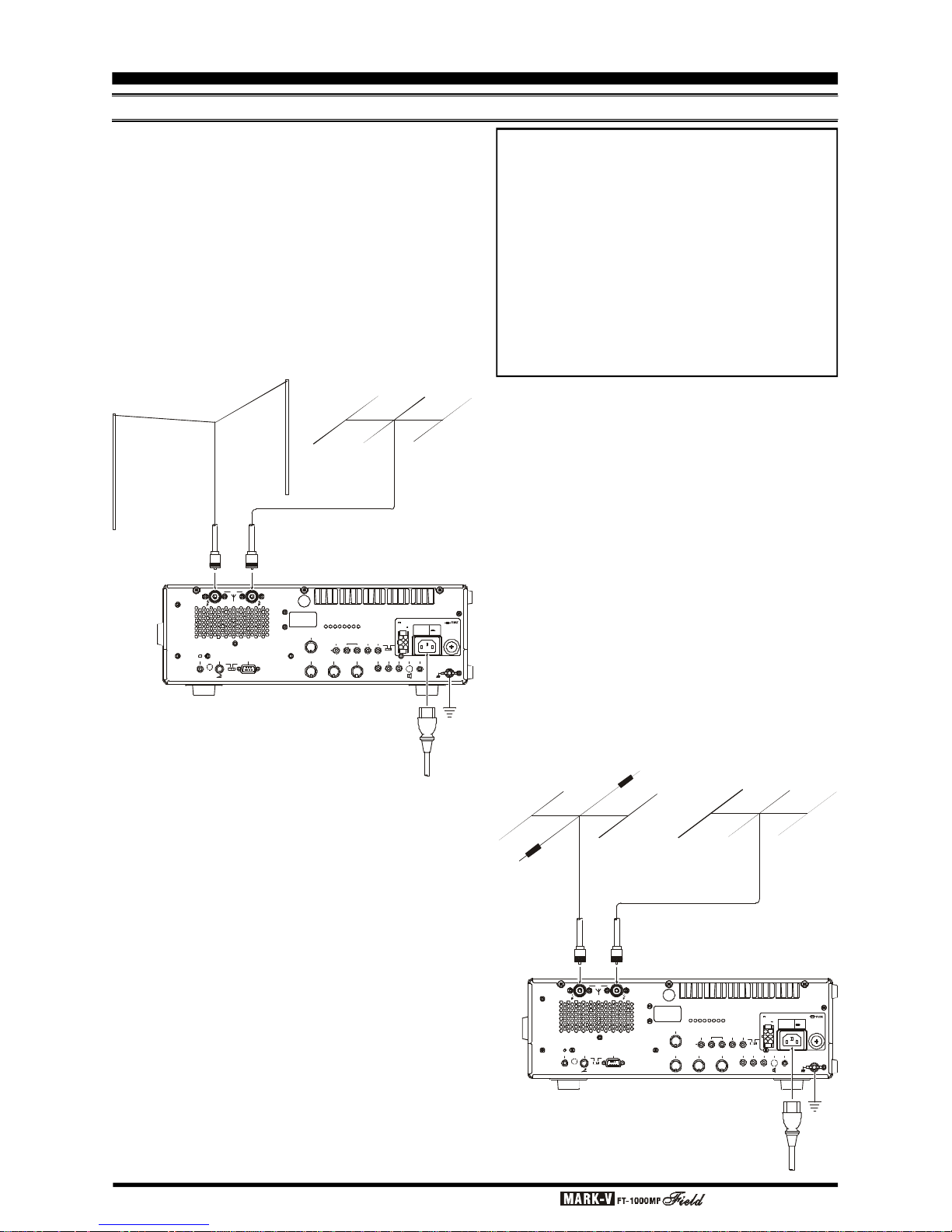
Page 20 OPERATING MANUAL
ACCESSORY INSTALLATION
ANTENNA CONNECTIONS
The MARK-V
FT-1000MP
Field’s three antenna connectors, plus innovative microprocessor-based
memory and switching circuits, provide excellent flexibility in setting up your antenna connections.
Typical antenna configurations are shown below.
Remember that Antenna A and Antenna B (which are
“SO-239” or “M” connectors) may be used for transmission and reception, while the RX Antenna port
(which is an “RCA” type connector) may only be used
for reception.
NOTE REGARDING
LARGE RECEIVE ANTENNAS
Although surge suppression is provided on all antenna ports, you may wish to consider building a
simple external circuit which will disconnect, on TX,
any antenna connected to the RX ANT IN jack,
particularly if you are using a very long wire antenna such as a Beverage. Very long antennas can
build up very high RF and static voltages on them,
and the circuit below may provide better protection
for your receiver’s input circuitry.
7MHz Dipole
14/21/28 MHz Tribander
MARK-V
FT-1000MP
Field
REMOTE
B AANT
KEY
BACKUP
LIN
CAT
DVS-2
BAND DATA
+13.8V TRV TX GNDRX ANT
PACKET RTTY PTT
EXT
ALC
EXT
SPKR
PATCH AF OUT
GND
OFF
OFF
IN OUT
CW
SIDETONE
ON
ACC
ON
OUTPUT
DC 13.8V
200 mA
INPUT
DC 13.8V
20 A
INPUT
AC 100-120V ~
50-60Hz 6A
FUSE
T8A
DC IN
~ AC IN
A
N
T
E
N
N
A
"
A
"
A
N
T
E
N
N
A
"
B
"
G
N
D
~
A
C
I
N
7/14/21 MHz Tribander
28 MHz 5el Yagi
MARK-V
FT-1000MP
Field
REMOTE
B AANT
KEY
BACKUP
LIN
CAT
DVS-2
BAND DATA
+13.8V TRV TX GNDRX ANT
PACKET RTTY PTT
EXT
ALC
EXT
SPKR
PATCH AF OUT
GND
OFF
OFF
IN OUT
CW
SIDETONE
ON
ACC
ON
OUTPUT
DC 13.8V
200 mA
INPUT
DC 13.8V
20 A
INPUT
AC 100-120V ~
50-60Hz 6A
FUSE
T8A
DC IN
~ AC IN
A
N
T
E
N
N
A
"
A
"
A
N
T
E
N
N
A
"
B
"
G
N
D
~
A
C
I
N
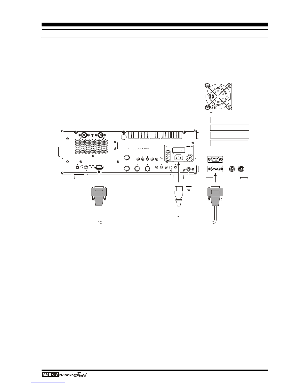
Page 21OPERATING MANUAL
REMOTE
B AANT
KEY BACKUP
LIN
CAT
DVS-2
BAND DATA
+13.8V
TRV
TX GND
RX ANT
PACKET RTTY PTT
EXT
ALC
EXT
SPKR
PATCH AF OUT
GND
OFF
OFF
IN OUT
CW
SIDETONE
ON
ACC
ON
OUTPUT
DC 13.8V
200 mA
INPUT
DC 13.8V
20 A
INPUT
AC 100-120V ~
50-60Hz 6A
FUSE
T8A
DC IN
~ AC IN
C
O
M
2
~
A
C
I
N
G
N
D
C
A
T
RS-232C Cable
ACCESSORY INSTALLATION
PERSONAL COMPUTER INTERFACING FOR CONTEST SOFTWARE, ETC.
The MARK-V
FT-1000MP
Field features a built-in
level converter, allowing direct connection from the rearpanel CAT jack to the serial port of your computer,
without the need for any external converter box.
When your software requests serial port configuration information, set it for “4800,N,8,2” (4800 baud, No
Parity, 8 Data Bits, and 2 Stop Bits). Be certain to configure and activate any required “TSR” (Terminate-andStay-Resident) utilities before beginning computer-controlled transceiver operation (your software’s instruction manual will describe any such requirement).
Details regarding the programming protocols for the
CAT system may be found beginning on page 86.
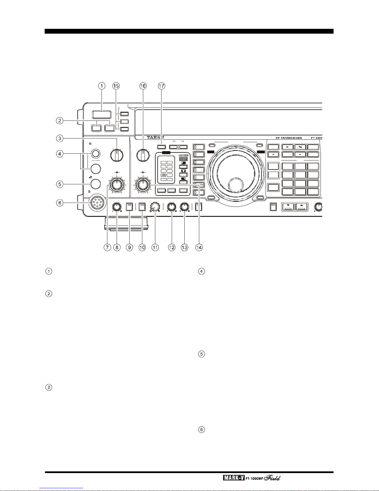
Page 22 OPERATING MANUAL
FRONT PANEL CONTROLS
This chapter describes each control and connector on the MARK-V
FT-1000MP
Field. You can just glance
through it quickly now, but some of the descriptions will be more meaningful if you take the time to read them in
detail now. If questions arise later while proceeding through the operation chapter, you can return to this chapter
with the set powered up for control knob clarification. Some controls and switches are disabled under certain
conditions.
POWER Button
This button turns the transceiver on and off.
MOX & VOX Buttons
[
MOX] may be used in place of a microphone PTT
switch or footswitch to activate the transmitter, when
depressed. It must be in the undepressed position for
reception.
[
VOX] enables automatic voice-actuated transmit-
ter switching in the SSB, AM and FM modes, and “semibreak-in” keying in CW mode. The controls affecting
VOX operation are located in the top access panel.
Menu Selection 7-5 sets the receiver recovery time during semi-break-in CW operation.
AGC Selector Knob
Selects main receiver Automatic Gain Control decay time for most comfortable reception, or disables
receiver AGC (off). Normally this switch is set to the
“AUTO” position. Strong signals will cause distortion if
this selector is set to “OFF.”
KEY
MIC
POWER
MOX VOX
METER
IC/SWR
ALC/COMP
VCC/MIC
A
B
PHONES
AGC
MIC
AF
GAINRFGAIN
PROC
FAST 0
6
12
18
dB
( )
OFF SLOW
AUTO
ATT
240
120
60
A
IPO A/B
ANT
RX
RX
MAIN VFO-A
TX
RCL
7
3
QMB BAND
STO
DUAL
M A
A B
M CK A M
M GRP
RPT
A B
VFO/
MEM
FAST LOCK
OFF
B
C
D
OFFOFF
APF
APF
NR
LSB
USB
CW
AM
FM
PKT
CLASS-A AF REVSQL SUB SMONIRF PWR MONI SUB AFPROC
NR
1.81104217SUBDE3.5214524.58290186289ENT
DOWN
UP
VRF
IDBT
EDSP
PHONES Jack
A ¼-inch and 3.5 mm, 3-contact jack accept either
monaural or stereo headphones with 2- or 3-contact
plugs. When a plug is inserted, the loudspeaker is disabled. With stereo headphones such as the optional
YH-77STA, you can monitor both receiver channels at
the same time during dual reception. In this case, the
headphone HP controls (page 32) beneath the top access panel adjust the default levels for mixed, separate, or monaural headphone operation.
KEY Jack
This ¼-inch, 3-contact jack accepts a CW key or
keyer paddles (for the built-in electronic keyer), or output from an external electronic keyer. You cannot use
a 2-contact plug in this jack (to do so produces a constant “key down” condition). Pinout is shown on page
4. Key up voltage is 5 V, and key down current is 0.5
mA. There is another jack with the same name, connected in parallel with this jack, on the rear panel.
MIC Jack
This 8-pin jack accepts input from the MH-31B8D
Microphone. MIC connector pinout is shown on page
4. Proper microphone input impedance is 500 ~ 600
Ohms.
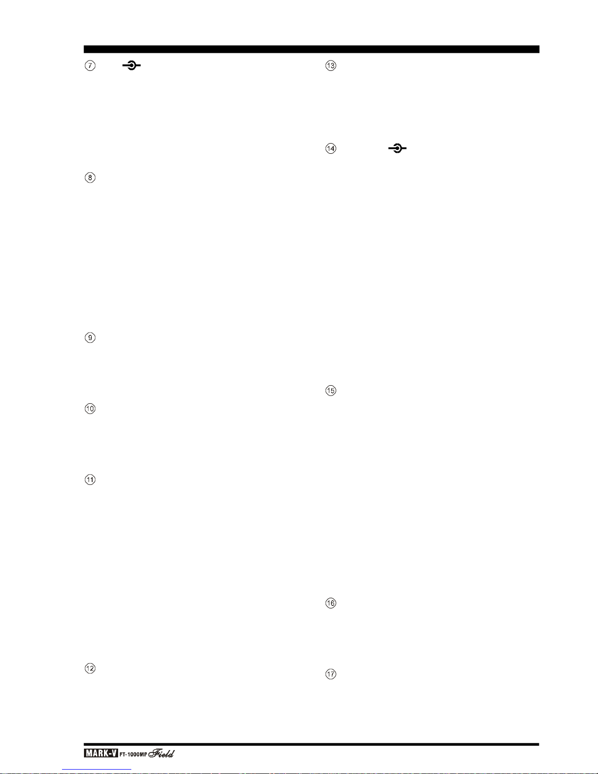
Page 23OPERATING MANUAL
MIC PROC Knob
The inner MIC control adjusts the microphone input level for (non-processed) SSB and AM transmission.
The outer PROC control sets the compression (input) level of the transmitter RF speech processor in
the SSB modes, when activated by the button with the
same name.
RF PWR Knob
This control adjusts the transmitter’s output power
in all modes. The adjustment range is from approximately 5 to 100 watts, except in the AM mode, where
the permitted carrier level is about 5 to 25 watts. This
knob also controls the carrier level for CW transmission. In setting the output power, the ALC function of
the meter should always be monitored, to avoid
overdriving the transmitter final amplifier.
In the “Class A” SSB operating mode, the adjustment range for power output will be between approximately 5 and 25 watts.
PROC Button
This button enables the RF speech processor for
SSB transmission. Processing level is set by the outer
control with the same name. While activated, the LED
in this button glows red.
MONI Button
This orange button enables the transmit (RF) monitor in all modes (except CW, in which the monitor function is always on, to produce the sidetone). While activated, the LED in this button glows red.
SUB AF Knob
The SUB AF control adjusts the audio volume of
the sub receiver VFO in the speaker or headphones.
The AF GAIN control, located above, and this SUB
AF control can be rotated to adjust the relative balance of receiver audio between the two receiver channels during dual reception.
Menu selection 2-8 (AF GAin) allows the SUB AF
control to be changed into a “Balance” control for the
two audio channels, if desired. In this case, the AF GAIN
control (see next column) will adjust the volume level
for both the Main and Sub receivers, while the SUB AF
control will control the balance. See page 101 for details.
MONI Knob
When activated by the [MONI] button (above), the
audio level of the transmit RF monitor during transmission (relative to the AF GAIN control) is adjusted by
this control.
FRONT PANEL CONTROLS
SQL Knob
This control sets the signal level threshold at which
main VFO-A receiver audio is muted (and the green
“MAIN BUSY” display indicator turns off), in all modes.
This control is normally kept fully counter-clockwise,
except when scanning and during FM operation.
AF GAIN RF GAIN Knob
The inner AF GAIN control adjusts the audio volume of the main receiver VFO in the speaker or headphones.
The outer RF GAIN control adjusts the receiver
signal level in front of the main receiver 1st mixer (via
PIN diodes), and also the gain of the main receiver IF
amplifiers.
It is normally set fully clockwise for maximum sensitivity. When rotated counter-clockwise, the S-meter minimum deflection point will move up the scale. The peak
deflection for a particular signal will remain the same if it
is greater than the level set by this control, but the main
receiver will be less sensitive to weaker signals.
This control also affects the SQL setting for main
VFO-A, and should be preset fully clockwise when setting the squelch threshold for the VFO or on a recalled
memory.
METER Selector Switches
These switches determine the function of the multifunction meter during transmission. The meanings of
the abbreviations are as follows:
IC/SWR - Final amplifier collector current
(Amps) and Standing Wave Ratio
(forward: reflected).
ALC/COMP - Relative Automatic Level Control
voltage and RF speech compressor
level (in dB, for SSB modes only).
VCC/MIC - Final amplifier collector voltage and
microphone gain input level.
The meter indicates power output and the selected
parameter during transmission, and signal strength in
S-units during reception (on the main receiver). Each
S-unit is approximately 6 dB.
ATT Selector Knob
This knob inserts 6, 12, or 18 dB (1, 2, or 3 S-units)
of attenuation before the mixer to suppress band noise
and reduce the possibility of overload from very strong
signals.
IPO Button
The Intercept Point Optimization button may be
used to set optimum receiver front end characteristics
for a strong environment. Selecting IPO bypasses the
front end RF amplifier and feeds the received signals
directly to the first mixer.
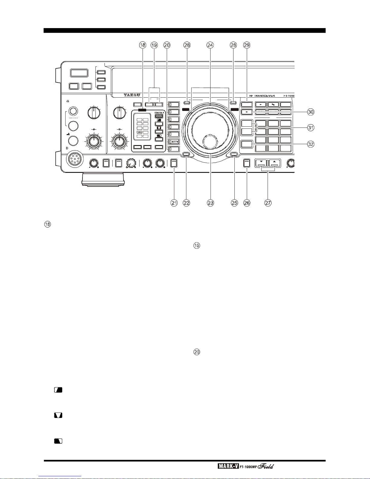
Page 24 OPERATING MANUAL
EDSP Filters
(A)
APF
Selects and indicates the bandwidth for the EDSP
CW audio peaking filter. Pressing the [APF] switch selects the bandwidth to be used for the EDSP CW audio
peaking filter, with available selections of 240(Hz)/
120(Hz)/60(Hz)/DATA (DATA is an optimized bandwidth
for FAX, PACKET or SSTV operation, user-optimized
via the Menu), or “OFF,” and the indicator changes according to the bandwidth selected. The most narrow
setting is highly useful for very-weak-signal CW work.
(B)
NR
Selects and indicates the setting of the EDSP
Noise Reduction feature. Pressing the [NR] switch selects one of four EDSP noise reduction settings, and
the indicator changes according to the selection chosen (choose the selection providing the most effective
reduction of noise under current operating conditions).
(C)
CONTOUR
Press one of these four switches to select the de-
sired EDSP (CONTOUR) filter.
: Low Cut Filter (
High-frequency emphasis
)
Pressing this button activates the EDSP Low Cut
Filter; the CONTOUR LED will glow green.
:Mid Cut Filter (
High- & Low-frequency emphasis
)
Pressing this button activates the EDSP Medium
Cut Filter; the CONTOUR LED will glow orange.
: High Cut Filter (
Low-frequencies emphasis
)
Pressing this button activates the EDSP High Cut
Filter; the CONTOUR LED will glow red.
OFF:
EDSP filter is off; the CONTOUR LED will go out.
ANT [A/B RX] Buttons
[
A/B] - Pressing this selects either the ANT A or B
jack on the rear panel, and allows convenient antenna switching at the press of a
button. The selected antenna jack is also
indicated at the top of the display (above
the channel group number).
[RX]
- Normally, the antenna connected to the ANT
A or B jack is used for receive (and always
used for transmitting). When this switch is
pressed (display indicator on), an antenna
connected to the RX ANT IN jack is used
during receive.
MODE Selection Buttons
These momentary buttons select the operating
mode, indicated by the LED in each button. Pressing
AM, CW, RTTY, or PKT multiple times will switch between the alternate operating features that can be used
by these modes (covered later). Also, when you press
and hold in the [PKT] key for one second, the userprogrammed custom function setting mode will be activated.
FRONT PANEL CONTROLS
KEY
MIC
POWER
MOX VOX
METER
IC/SWR
ALC/COMP
VCC/MIC
A
B
PHONES
AGC
MIC
AF
GAINRFGAIN
PROC
FAST 0
6
12
18
dB
( )
OFF SLOW
AUTO
ATT
240
120
60
A
IPO A/B
ANT
RX
RX MAIN VFO-A TX
RCL
7
3
QMB BAND
STO
DUAL
M A
A B
M CK A M
M GRP
RPT
A B
VFO/
MEM
FAST LOCK
OFF
B
C
D
OFFOFF
APF
APF
NR
LSB
USB
CW
AM
FM
PKT
CLASS-A AF REVSQL SUB SMONIRF PWR MONI SUB AFPROC
NR
1.81104217SUBDE3.5214524.58290186289ENT
DOWN
UP
VRF
IDBT
EDSP

Page 25OPERATING MANUAL
CLASS-A Button
This button changes the final amplifier operating
mode to Class-A. When operating the final amplifier
in the Class-A mode, the maximum output power will
be reduced to approximately 25 watts, and the LED
inside this button will glow red. Operating SSB in Class-
A yields an ultra-clean signal waveform.
FAST Button
For fast tuning, press this button (the “FAST” icon
will appear), then rotate the main or sub tuning knobs
(or press the UP
(p)
or DOWN
(q)
button). The tuning
rate will increase ten times.
MAIN VFO-A Tuning Knob
This large knob adjusts the operating frequency of
Main VFO-A (or a recalled memory). Default tuning
increments are 10 Hz (100 Hz in AM and FM modes).
When the [FAST] button has been pressed, the increments are 10x these sizes. See the table on page 38
for a listing of all available steps.
Shuttle Jog and VRF & IDBT Buttons
The Shuttle Jog ring allows fine or rapid frequency
excursions with just a slight turn of your hand. Rotating
the ring slightly either to the left or the right tunes downward or upward a few steps. The tuning rate increases
the farther the ring is rotated.
Pressing the [VRF] button on the left side of the
Shuttle Jog activates the VRF (Variable RF Front-end
Filter), which adds a narrow input preselector filter into
the RF receiver circuit on the 160-20 meter Amateur
bands. Its passband can be tuned by rotating the VRF/
MEM CH knob, located on the upper right corner of
the front panel, for maximum sensitivity and out-of-band
interference rejection.
Pressing the [IDBT] button on the right side of the
Shuttle Jog activates the IDBT (Interlocked Digital
Bandwidth Tracking) System, which matches the EDSP
(Bandwidth) filter characteristics to the settings of the
SHIFT and WIDTH knobs. Thus, it is not necessary to
re-adjust the EDSP settings if you change the (IF)
WIDTH and/or SHIFT settings; the EDSP settings will
automatically follow those of the higher-frequency IF
passband.
LOCK Button
This button toggles locking of the main tuning knob
to prevent accidental frequency changes. “LOCK” is
displayed in a red box below and to the left of the main
frequency display field when this command is active
(the tuning knob can still be turned, but it does nothing). Press [LOCK] again to enable the tuning knob.
AF REV Button
Pressing this reverses the main/sub receiver audio adjusted using the AF GAIN knob and SUB AF
knob. When activated, the LED inside this button glows
red.
DOWN
(q)
& UP
(p)
Buttons
Pressing either of these buttons momentarily steps
the operating frequency down or up 100 kHz, respectively. Pressing and holding the [FAST] button while
pressing one of these buttons steps the frequency down
or up 1 MHz. Continue holding either button for repeated
stepping.
MAIN VFO-A [RX & TX Switch-LED
]
These combination lamp-switches select and indicate the transmit/receive status of the main tuning knob
and display. When the green “RX” lamp is lit, the re-
ceiving frequency is under control of the main knob
and display (either VFO-A or a recalled memory channel). When the red “TX” lamp is lit, the transmitting
frequency is under control of the main knob and display. Thus, for “normal” (non-split) operation, both the
red and green lamps associated with the main tuning
knob will be illuminated.
VFO/MEM Button
This button toggles main receiver operation between the memory channel and the main VFO-A. Either “VFO,” “MEM,” or “M TUNE” will be displayed to
the left of the main frequency display field to indicate
the current selection. If a displayed memory has been
retuned, pressing this button returns the display to the
original memory contents, and pressing it again returns
operation to the Main VFO.
[MuA] Button
Pressing this button momentarily displays the contents of the currently-selected memory channel for three
seconds. Holding this button for ½ second copies the
data from the currently selected memory to the Main
VFO-A, as two beeps sound. Previous data in the Main
VFO will be overwritten.
QMB Buttons
[
RCL] (Recall) - Recalls one of up to five Quick
Memory Bank memories for operation.
[
STO] (Store) - Pressing this copies operating pa-
rameters into consecutive QMB
Memories.
[
DUAL] Button
This button activates dual-channel reception with
the main and sub receivers. When this function is active, “DUAL” will be displayed in a box at the left edge
of the display.
FRONT PANEL CONTROLS
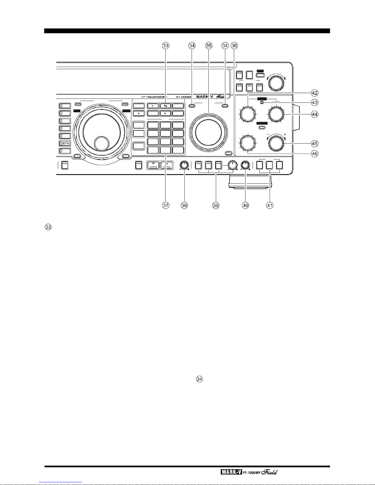
Page 26 OPERATING MANUAL
VFO & Memory Control
[
AuB] Button:
Pressing this button for ½ second (until the double
beep) transfers data from the main display (either Main
VFO-A or a recalled memory channel) to Sub VFO-B,
overwriting any previous contents in the Sub VFO. Use
this key to set both Main and Sub Receivers to the
same frequency and mode.
[
A
u
t
B] Button:
Pressing this button momentarily exchanges the
contents of Main VFO-A (or a recalled memory channel), and Sub VFO-B. No data is lost.
[
M GRP] Button:
When more than one memory group has been enabled, pressing this button limits selection and scanning to those memories within the selected group.
[
M CK] (Memory Check) Button:
This key displays the contents of memory channels without disturbing operation. When pressed, “M
CK” is displayed above the channel number, and each
memory channel can then be checked on the Sub
Receiver display by rotating the VRF/MEM CH selector. Empty memory channels display as two decimals,
with no frequency digits. Press this button again to
cancel memory checking.
[
AuM] Button:
Pressing and holding in this key for ½ second (until the double beep) copies the current operating data
from Main VFO-A, or a recalled memory, to the currently selected memory channel, overwriting any previous data stored there. Also, pressing and holding this
button after recalling a memory, without first retuning,
causes the memory channel to be “masked,” and repeating the process restores the masked memory.
[
RPT] Button:
For 29 MHz FM operation, this button activates the
standard HF FM repeater offset. Pressing [RPT] once
or twice while receiving causes the transmit frequency
to be shifted 100 kHz below or above the receiving
frequency, respectively. A selectable CTCSS
subaudible tone is also transmitted automatically when
using this feature, to allow access to repeaters that
require it. Pressing [RPT] a third time cancels repeater
shift operation.
SUB VFO-B [RX & TX Switch-LED
]
These lamps select and indicate the current status
of Sub VFO-B. When the green “RX” lamp is lit, the
receiving frequency is under control of SUB VFO-B.
When the red “TX” lamp is lit, the transmitting frequency
is under control of SUB VFO-B. During dual receive
operation, the green “RX” lamps above both tuning
knobs Main and Sub) will be illuminated.
FRONT PANEL CONTROLS
RX MAIN VFO-A
SUB VFO-BRX TX
NOTCH
TX
RCL
7
3
QMB
BAND
STO
DUAL
M A
A B
M CK A M
M GRP
RPT
A B
VFO/
MEM
FAST LOCK
LOCK
LSB
USB
CW
AM
FM
PKT
CLASS-A AF REV SPOT BK-IN KEYERSUB SQL SPEED
TUNER
NOR
SHIFT
NOTCH
WIDTH
CLAR
NAR1 NAR2
BAND WIDTH
NB
VRF
VRF/MEM CH
PITCH CLAR
CLEARRX TX
1.8
1
10
4
21
7
SUB
DE
3.5
2
14
5
24.5
8
29
0
18
6
28
9
ENT
DOWN UP
DWN
UP
IDBT
VRF IDBT

Page 27OPERATING MANUAL
SUB VFO-B Tuning Knob
This knob adjusts the Sub VFO-B operating frequency. The available tuning increments are the same
as described for the main tuning knob, although each
tuning knob’s increments may be set independently
(see page 38).
[
LOCK] Button
This button toggles locking of SUB VFO-B tuning
to prevent accidental frequency changes. The red indicator in the display glows when this command is active (the tuning knob can still be turned, but it does
nothing). Press the [LOCK] button again to re-enable
the tuning knob.
BAND (Keypad
)
The keypad provides one-touch band selection, or
direct frequency entry. Normally, pressing one of the
ten white numbered keys selects the corresponding
(MHz) amateur band for operation (pressing the SUB
button first, followed by a [BAND] key, selects that band
for the Sub VFO). If you press the white numbered key
for the band you are already on, you will select the
alternate subband VFO on that band. See the “Opera-
tion” chapter for details.
If the [ENT] key is pressed first, the yellow labels
on the keys become effective, for manually entering
any frequency one digit at a time; press [SUB(CE
)]
then [ENT] to enter Sub-VFO frequencies directly.
SUB SQL Knob
This separate control sets the signal level threshold at which SUB VFO-B receiver audio is muted (and
the green “SUB BUSY” display indicator turns off), in
all modes. This control is normally kept fully CCW,
except when scanning and during FM operation.
CW and Electronic Keyer Controls
[
SPOT] button turns the CW receiver spotting het-
erodyne oscillator on and off.
[
BK-IN] button turns full break-in (QSK) CW op-
eration on and off.
[
KEYER] button toggles the internal CW keyer on/
off, as indicated by the LED above this button.
[
SPEED] knob adjusts the keying speed of the
keyer.
PITCH Knob
Rotate this control to select your desired CW tone
pitch (from 300~1050 Hz, in 50 Hz increments), as
shown in the display. The Tx sidetone, receiver IF passband, and display offset from the BFO (carrier) frequency are all affected simultaneously.
[
CLAR] Buttons
Pressing the [RX] button activates the CLAR knob,
to allow offsetting the receiving frequency temporarily
(see item below). The [TX] button provides the same
function for the transmit frequency. If both buttons are
pressed, the receiver and transmitter are both offset
from the original frequency. Pressing the [CLEAR] button zeroes any offset tuned by the CLAR knob. Each
memory and VFO retains all Clarifier settings independently.
SHIFT Knob
This knob offsets the center frequency of the IF
passband when rotated from its “normal” (center) position. This control functions in all modes except FM.
When the IDBT System is activated by pressing
the [IDBT] button on the Shuttle Jog, the EDSP
(Bandpass) filter’s passband offset changes according to this knob’s setting.
IDBT Indicator
This red indicator lights up when the IDBT System
is activated by pressing the [IDBT] button on the Shuttle
Jog. When this indicator is illuminated, the EDSP
(Bandpass) filter’s bandwidth and center frequency
change according to the SHIFT and WIDTH knob settings.
WIDTH Knob
This knob, when turned from center, reduces the
overall IF bandwidth from either the lower or upper side,
from the maximum selected by the [BANDWIDTH] buttons.
When the IDBT feature is activated by pressing
the [IDBT] button on the Shuttle Jog, the EDSP
(Bandpass) filter’s passband width is reduced according to this knob’s setting.
CLAR Knob
This knob tunes the Clarifier offset frequency up to
9.99 kHz when activated by the CLAR [RX] [TX] buttons just below it (a 3-digit display appears in the center of the display (if enabled) when the Clarifier is active).
NOTCH Knob
This knob adjusts the IF notch frequency when this
feature is activated by the [NOTCH] button located
above this knob. When activated, the LED inside the
[
NOTCH] button glows red.
Note that the setting of menu selection 2-9 may dis-
able the action of this knob (if menu selection 2-9 is set
to Auto DSP). With this selection, the EDSP Automatic
Notch will be activated, and the IF Notch will be disabled.
FRONT PANEL CONTROLS
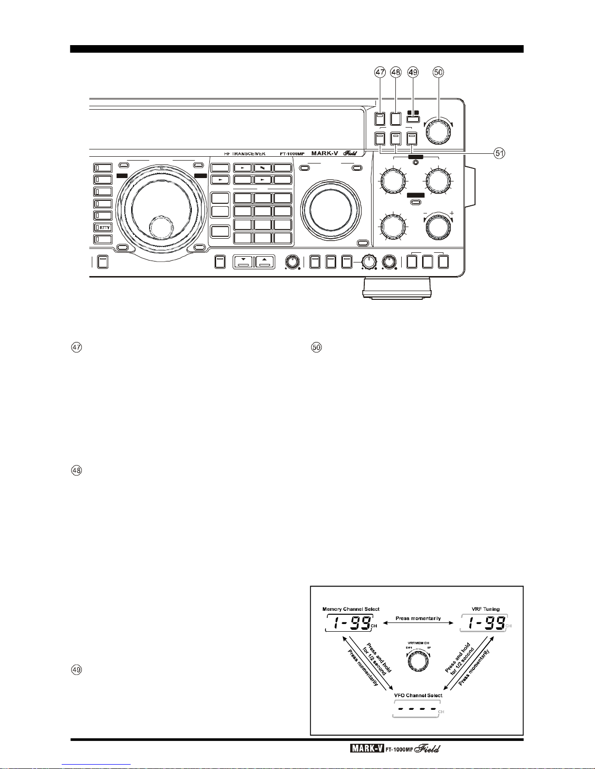
Page 28 OPERATING MANUAL
NB Button
Pressing this button activates the IF Noise Blanker,
which may help reduce many different types of manmade impulse noise (but not atmospherics). When the
Noise Blanker is activated, the LED inside button will
glow red.
You can select the Noise Blanker Type (for shortduration pulses or for long-duration pulses) and its
blanking level via menu selection 2-8.
[
TUNER] Button
This is the on/off switch for the MARK-V
FT-1000MP
Field’s Automatic Antenna Tuner.
Pressing this button momentarily places the antenna tuner in line between the transmitter final amplifier and the main antenna jack. Reception is not affected.
Pressing and holding this button for ½ second while
receiving in an amateur band activates the transmitter
for a few seconds while the automatic antenna tuner
rematches the antenna system impedance for minimum SWR. The resulting settings are automatically
stored in one of the antenna tuner’s 39 memories, for
instant automatic recall later when the receiver is tuned
near the same frequency.
VRF
Indicator
This indicator glows red when the VRF feature is
activated by pressing the [VRF] button on the Shuttle
Jog.
VRF/MEM CH Knob
When the VRF feature is engaged, use this
detended knob to tune the passband of the narrow input preselector filter manually for maximum receiver
sensitivity (and out-of-band interference rejection).
At other times (when the VRF feature is “off”), this
knob selects the operating memory channel when the
memories are active (but not retuned). When the VFO
or memory tune functions of the main display are active, turning this knob causes the Sub VFO display to
temporarily show the frequencies of the memories
(memory check), without otherwise affecting operation.
The channel number of the selected memory is displayed at all times at the center right of the display (in
front of “CH”).
Pressing and holding this knob for ½ second enables the “VFO Step” feature, which allows
“channellizing” the VFO for quick frequency navigation.
Menu Selection 1-5 sets the VFO Channel step size.
FRONT PANEL CONTROLS
VRF/MEM CH Knob Sequence
Note: VRF only functions on the 160-20 M Amateur Bands
RX MAIN VFO-A
SUB VFO-BRX TX
NOTCH
TX
RCL
7
3
QMB BAND
STO
DUAL
M A
A B
M CK A M
M GRP
RPT
A B
VFO/
MEM
FAST LOCK
LOCK
LSB
USB
CW
AM
FM
PKT
CLASS-A AF REV SPOT BK-IN KEYERSUB SQL SPEED
TUNER
NOR
SHIFT
NOTCH
WIDTH
CLAR
NAR1 NAR2
BAND WIDTH
NB
VRF
VRF/MEM CH
PITCH CLAR
CLEARRX TX
1.8
1
10
4
21
7
SUB
DE
3.5
2
14
5
24.5
8
29
0
18
6
28
9
ENT
DOWN UP
DWN
UP
IDBT
VRF IDBT
 Loading...