

Page 1

Alveo Programming
Cable User Guide
UG1377 (v2019.1) September 17, 2019
Page 2

Revision History
Section
Revision Summary
General updates.
No technical content updates.
08/30/2019 Version 2019.1
Chapter 1: Introduction
Provided a general overview of the card.
Provided names of the supported cards and links
to each
Chapter 2: Preventing ESD Damage
Updated Figure 1.
Updated Tables 1-4.
Chapter 3: Setting Up the System
Updated Figures 2-7.
Revised steps to set up ribbon cable.
Added section “Connecting Alveo Programming
Module to the Card”
Chapter 4: Programming the Alveo Card
Described how to connect and program the card.
Appendix A: Board Specifications
Added physical descriptions of the board..
Entire Document
Edited for grammar and mechanics.
06/21/2019 Version 2019.1
Initial Release
N/A
Send Feedback
The following table shows the revision history for this document.
09/17/2019 Version 2019.1
UG1377 (v2019.1) September 17, 2019
2 Alveo Programming Cable User Guide
Page 3

Table of Contents
Send Feedback
Revision History .......................................................................................................................................................................... 2
Chapter 1: Introduction ................................................................................................................................................................ 4
Overview ........................................................................................................................................................................................ 4
Chapter 2: Board Overview ......................................................................................................................................................... 5
Preventing ESD Damage ......................................................................................................................................................... 6
Board Component Descriptions ........................................................................................................................................... 6
Chapter 3: Setting Up the System with the Programming Cable ................................................................................. 8
Connecting the Ribbon Cable ............................................................................................................................................... 8
Disconnecting the Ribbon Cable ....................................................................................................................................... 10
Connecting Alveo Programming Module to Card ...................................................................................................... 10
Chapter 4: Programming the Alveo Card ........................................................................................................................... 12
Appendix A: Board Specifications ......................................................................................................................................... 15
Dimensions (Square Form-Factor) .................................................................................................................................... 15
Environmental .......................................................................................................................................................................... 15
Humidity ..................................................................................................................................................................................... 15
Legal Notices
Please Read: Important Legal Notices ............................................................................................................................ 16
UG1377 (v2019.1) September 17, 2019
3 Alveo Programming Cable User Guide
Page 4

Chapter 1: Introduction
Send Feedback
Overview
The Alveo™ Programming Cable provides development access for debug-port enabled Alveo Cards
allowing the card to be programmed. The Alveo programming cable consists of a programming
module, ribbon cable and USB cable. Debug-port enabled Alveo cards have a 2x15-pin connector,
which connects to the programming module via the ribbon cable. The programming module connects
to the host computer via micro-USB, which also provides power. This setup is shown in Figure 7.
The following cards include a debug-port and support the Alveo Programming Cable:
• U50/U50DD
UG1377 (v2019.1) September 17, 2019
4 Alveo Programming Cable User Guide
Page 5

Chapter 2: Board Overview
Call-Out No.
Interface
Description
1
2x15-pin debug connector
Provides connection between the programming
module and Alveo card. Used for programming the
FPGA.
2
Micro USB Connector Port 1
Provides connection between host system, with Vivado
installed, and the programming module. Used for
programming the Alveo card.
3
Unused
Used exclusively by Xilinx for manufacturing.
Unused for development tool flows.
IMPORTANT: While there are additional interfaces on the board, these will not be accessible on the
housed version of the DMC. Figure 1 is for visual reference only and might not reflect the current
revision of the board. There could be multiple revisions of this board. The specific details
concerning the differences between revisions are not captured in this document .
Send Feedback
The Alveo™ programming module, along with a callout of the available interfaces, is shown in the
following figure. The description of each call-out is given in the table below with additional information
provided in Board Component Descriptions in Chapter 2.
Table 1: Alveo Programming Module Interface Descriptions
Figure 1: Alveo Programming Module Interface Locations
UG1377 (v2019.1) September 17, 2019
5 Alveo Programming Cable User Guide
Page 6

Preventing ESD Damage
CAUTION! ESD can damage electronic components when they are improperly handled and can
result in total or intermittent failures. Always follow ESD-prevention procedures when removing and
replacing components.
Send Feedback
In order to preserve the integrity of the components, follow the recommendations listed below:
• Use an ESD wrist or ankle strap and ensure that it makes skin contact. Connect the equipment
end of the strap to an unpainted metal surface on the chassis.
• Avoid touching the adapter against your clothing. The wrist strap protects components from
ESD on the body only.
• Handle the adapter by its bracket or edges only. Avoid touching the printed circuit board or the
connectors.
• Put the adapter down only on an antistatic surface such as the bag supplied in your kit.
• If you are returning the adapter to Xilinx Product Support, place it back in its antistatic bag
immediately.
Board Component Descriptions
Debug Header for Main Board Interconnection
The programming module is populated with a 2x15-pin debug connector (Callout 1 in Figure 1) which
connects to the Alveo card via a ribbon cable.
2x15 Connector Details:
• Manufacturer: SAMTEC
• Part Number: FTSH-115-01-F-D-RA-K
• Description: CONN HEADER R/A 30POS 1.27MM
Connector debug header pin definitions are given in Table 2.
Micro USB Connectors
The programming module has two micro-USB connectors (Callouts 2 and 3 in Figure 1), one for each
FT4232 USB to multi-protocol converter. Connect the external micro-USB cable from the host to the
Micro-USB Connector 1 (Callout 2 in Figure 1). Micro-USB Connector 2 should be left unused (Callout 3
in Figure 1).
Pin description of the micro-USB connector is provided in Table 2.
UG1377 (v2019.1) September 17, 2019
6 Alveo Programming Cable User Guide
Page 7

Table 2: Micro USB Connectors
Pin No.
Signal Name
Functionality
1
USB_VBUS
USB Power
2
USB_DN
USB Differential data -
3
USB_DP
USB Differential data +
4
USB_ID
USB ID
5
GND
Ground
6
GND
Shield Ground
7
GND
8
GND
9
GND
10
GND
11
GND
Item
No.
Quantity/
Board
Description
MANF
MANF_P/N
Remarks
1
1
Ribbon Cables / IDC Cables
.050" Tiger Eye IDC Ribbon
Cable Assembly, 1.27 mm,
30 Position, 6" length,
Female to Female
Samtec
FFSD-15-D-
06.00-01-N
Connection between
programming module and
Alveo card connector.
2
1
CABLE USB-A TO MICRO
USB-B 2M
Assmann
AK67421-2-R
Connection between
programming module and
external device (ie. host
computer)
Item
Number
Tool/Test
Utility
Manufacturer/Vendor
Version
Remarks
1
Vivado® Design
Suite
Xilinx
2019.1 or
later
For Xilinx FPGA - JTAG
programming
Send Feedback
Programming Cable
The required cables for the programming module are listed in Table 3.
Table 3: Maintenance Board Accessories
Tools
Table 4 lists the Xilinx tools to access the FPGA via the Alveo Programming Module.
Table 4: Test Tools/Utility
UG1377 (v2019.1) September 17, 2019
7 Alveo Programming Cable User Guide
Page 8
Chapter 3: Setting Up the System with the Programming Cable
IMPORTANT: The ribbon length you use can vary depending on your system setup. For ribbon
cable length greater than 5”, it is necessary to reduce the JTAG transfer frequency used by
Vivado® hardware manager from 15 MHz to 10 MHz when programming the card. Complete
details are given in Chapter 4.
Send Feedback
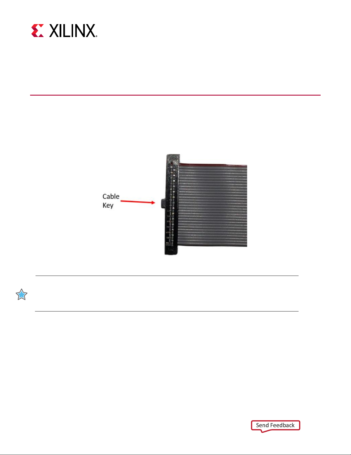
Connecting the Ribbon Cable
A 2x15 ribbon cable, as specified in Chapter 2, is required to connect between the Alveo™ card and the
programming module. When connecting the ribbon, ensure to align the cable key with the spacing on
the maintenance connector. The cable key is shown in the following image:
Figure 2: Ribbon Cable Key
Debug-port enabled Alveo cards have a 2x15-pin maintenance connector that attaches to the
corresponding connector on the programming module via the ribbon cable. As an example, the 2x15pin maintenance connector debug connector port for the Alveo U50 is shown below and the
corresponding connector on the programming module is shown in Figure 3.
UG1377 (v2019.1) September 17, 2019
8 Alveo Programming Cable User Guide
Page 9

Figure 3: Connecting Ribbon Cable to Debug Connector
IMPORTANT: Do not apply excessive force when connecting the ribbon cable as the
connector pins can be damaged or bent.
CAUTION! When installing or removing the ribbon cable, ensure the power is disconnected
on the Alveo card, host and server computers. Ensure proper ESD protection is followed. Refer
to Preventing ESD Damage for guidelines.
Send Feedback
Figure 4: Aligning Ribbon Cable to Alveo Maintenance Connector Port
When attaching the cable, apply gentle pressure and ensure the cable has a tight connection.
UG1377 (v2019.1) September 17, 2019
9 Alveo Programming Cable User Guide
Page 10

Disconnecting the Ribbon Cable
Send Feedback
When removing the ribbon from either the Alveo card or programming cable, firmly hold the ribbon
connector and pull the cable out in a straight line. Twisting or rotating the connector will damage the
connector pins on the Alveo card or programming module.
Connecting Alveo Programming Module to Card
This section provides the programming module connection to Alveo card procedures. Depending on
your system setup, the following installation steps may differ. A 15” cable is used in the following
example. Two adjacent PCI slots are necessary: one for the Alveo card and the other for ribbon cable
access.
1. Before installing the Alveo card, connect one end of the ribbon cable to the 2x15-pin maintenance
port on the Alveo card following the instructions outlined in Connecting the Ribbon Cable.
2. Power off the server and Install the Alveo card in the server. See the Alveo U50 Data Center
Accelerator Card Installation Guide (UG1370) for Alveo card installation steps.
3. When the card is installed, guide the ribbon cable through the adjacent PCI slot, providing enough
length to attach to the Alveo Programming Module.
4. Attach the second end of the ribbon cable to the maintenance connector on the Alveo
Programming Module following the instructions outlined in Connecting the Ribbon Cable. The
following figures show the subsequent setup from a top and side view.
UG1377 (v2019.1) September 17, 2019
Figure 5: Installed Alveo Card Connected to Alveo Programming Module – Top View
10 Alveo Programming Cable User Guide
Page 11

Figure 6: Installed Alveo Card Connected to Alveo Programming Module – Side View
Send Feedback
5. Replace the server cover.
6. Attach the micro-USB cable to USB Port 1 of the Alveo Programming Module. An image of both the
ribbon (on the left side) and USB connected (on the right side) is shown below.
Figure 7: Alveo Programming Module with Ribbon and USB Cables Connected
7. Guide the other end of the micro-USB cable to a location that is accessible by the host
The Alveo Programming Module is successfully installed and the server can now be powered on.
UG1377 (v2019.1) September 17, 2019
computer/laptop with Vivado installed.
11 Alveo Programming Cable User Guide
Page 12

Chapter 4: Programming the Alveo Card
Send Feedback
If you are using the SDAccel™ flow, the Alveo U50 Data Center Accelerator Card Installation Guide
(UG1370) provides the software installation instructions including programming the shell to the Alveo™
card. Traditional RTL-flow Alveo cards, enabled with the 2x15-maintenance port, can be programmed
using the Alveo Programming Module and the Vivado® hardware manager application.
To use this flow:
• Vivado hardware manager must be installed on your host machine or laptop.
• Alveo card must be installed (see Connecting Alveo Programming Module to Card) and the
server powered on.
• DMC connected as described in Connecting Alveo Programming Module to Card.
To connect and program the Alveo card using the Vivado hardware manager:
1. Attach the free end of the USB cable (coming from the Alveo Programming Module) to the host
computer; thus connecting the module and host computer.
2. Start Vivado on the host computer
3. Open the hardware manager by selecting Flow Navigator > Open Hardware Manager.
4. Select Tools > Auto Connect to open the target.
This will open a similar window as shown below. In this example, an Alveo U50 is connected.
Figure 8: Vivado Hardware Manager Auto-Connect
UG1377 (v2019.1) September 17, 2019
12 Alveo Programming Cable User Guide
Page 13

When using greater than a 5” long ribbon cable, it is necessary to change the JTAG transfer frequency
Send Feedback
from 15 MHz to 10 MHz. This lower frequency ensures proper signal integrity and ensures successful
programming. To change JTAG transfer frequency to 10 MHz, run the following Tcl command in the
hardware manager command line as shown in the below image:
set_property PARAM.FREQUENCY 1000000 [current_hw_target]
Figure 9: Changing JTAG Transfer Frequency via TCL Command
5. Choose the memory configuration part on the card.
a. Right click on target opened in this example ‘xcu50_0’, and select Add Configuration Memory
Device.
b. Select the memory associated with the card installed and click OK as shown below. For this
example, mt25qu01g-spi-x1_x2_x4 was selected.
c. When you are prompted to program the configuration memory device, click OK.
UG1377 (v2019.1) September 17, 2019
Figure 10: Select Memory Device
13 Alveo Programming Cable User Guide
Page 14

6. Select the desired .mcs file.
Send Feedback
7. In the Address Range drop-down list, select Entire Configuration Memory Device.
8. Click OK.
Figure 11: Program Configuration Memory
9. Disconnect the card in the Vivado hardware manager.
10. Disconnect the USB cable from your host computer.
11. Power-cycle the card. The card will now be updated.
UG1377 (v2019.1) September 17, 2019
14 Alveo Programming Cable User Guide
Page 15

Appendix A: Board Specifications
Send Feedback
Dimensions (Square Form-Factor)
• Height: 2.5 inch (6.35 cm)
• Length: 2.5 inch (6.35 cm)
• Thickness (±5%): 0.062 inch (0.1574 cm)
Environmental
• Temperature for U200 and U280
• Operating: 0°C to +55°C, Storage: -40°C to +75°C
Humidity
• 10% to 90% non-condensing
UG1377 (v2019.1) September 17, 2019
15 Alveo Programming Cable User Guide
Page 16

Legal Notices
Send Feedback
Please Read: Important Legal Notices
The information disclosed to you hereunder (the “Materials”) is provided solely for the selection and use of Xilinx products. To
the maximum extent permitted by applicable law: (1) Materials are made available "AS IS" and with all faults, Xilinx hereby
DISCLAIMS ALL WARRANTIES AND CONDITIONS, EXPRESS, IMPLIED, OR STATUTORY, INCLUDING BUT NOT
LIMITED TO WARRANTIES OF MERCHANTABILITY, NON-INFRINGEMENT, OR FITNESS FOR ANY PARTICULAR
PURPOSE; and (2) Xilinx shall not be liable (whether in contract or tort, including negligence, or under any other theory of
liability) for any loss or damage of any kind or nature related to, arising under, or in connection with, the Materials (including
your use of the Materials), including for any direct, indirect, special, incidental, or consequential loss or damage (including loss
of data, profits, goodwill, or any type of loss or damage suffered as a result of any action brought by a third party) even if such
damage or loss was reasonably foreseeable or Xilinx had been advised of the possibility of the same. Xilinx assumes no
obligation to correct any errors contained in the Materials or to notify you of updates to the Materials or to product
specifications. You may not reproduce, modify, distribute, or publicly display the Materials without prior written consent.
Certain products are subject to the terms and conditions of Xilinx’s limited warranty, please refer to Xilinx’s Terms of Sale
which can be viewed at https://www.xilinx.com/legal.htm#tos; IP cores may be subject to warranty and support terms
contained in a license issued to you by Xilinx. Xilinx products are not designed or intended to be fail-safe or for use in any
application requiring fail-safe performance; you assume sole risk and liability for use of Xilinx products in such critical
applications, please refer to Xilinx’s Terms of Sale which can be viewed at https://www.xilinx.com/legal.htm#tos.
AUTOMOTIVE APPLICATIONS DISCLAIMER
AUTOMOTIVE PRODUCTS (IDENTIFIED AS “XA” IN THE PART NUMBER) ARE NOT WARRANTED FOR USE IN THE
DEPLOYMENT OF AIRBAGS OR FOR USE IN APPLICATIONS THAT AFFECT CONTROL OF A VEHICLE (“SAFETY
APPLICATION”) UNLESS THERE IS A SAFETY CONCEPT OR REDUNDANCY FEATURE CONSISTENT WITH THE ISO
26262 AUTOMOTIVE SAFETY STANDARD (“SAFETY DESIGN”). CUSTOMER SHALL, PRIOR TO USING OR
DISTRIBUTING ANY SYSTEMS THAT INCORPORATE PRODUCTS, THOROUGHLY TEST SUCH SYSTEMS FOR
SAFETY PURPOSES. USE OF PRODUCTS IN A SAFETY APPLICATION WITHOUT A SAFETY DESIGN IS FULLY AT THE
RISK OF CUSTOMER, SUBJECT ONLY TO APPLICABLE LAWS AND REGULATIONS GOVERNING LIMITATIONS ON
PRODUCT LIABILITY.
© Copyright 2019 Xilinx, Inc. Xilinx, the Xilinx logo, Alveo, Artix, Kintex, Spartan, Versal, Virtex, Zynq, and other designated
brands included herein are trademarks of Xilinx in the United States and other countries. All other trademarks are the property
of their respective owners.
UG1377 (v2019.1) September 17, 2019
16 Alveo Programming Cable User Guide
 Loading...