

Page 1

WorkCentre 5021/5019
Service Documentation
WC 5021/5019 Service Documentation
702P00886
Initial Issue
08/2012
***Xerox Private Data***
All service documentation is supplied to Xerox external customers for informational purposes
only. Xerox service documentation is intended for use by certified, product-trained service personnel only. Xerox does not warrant or represent that it will notify or provide to such customer
any future change to this documentation. Customer performed service of equipment, or m odules, components, or parts of such equipment may affect whether Xerox is responsible to fix
machine defects under the warranty offered by Xerox with respect to such equipment. You
should consult the applicable warranty for its terms regarding customer or third-party provided
service.
If the customer services such equipment, modules, components or parts thereof, the customer
releases Xerox from any and all liability for the customer actions, and the custom er agrees to
indemnify, defend and hold xerox harmless from any third party claims which arise directly or
indirectly for such service.
While Xerox has tried to make the documentation accurate, Xerox will have no liability arising
out of any inaccuracies or omissions. Changes are periodically made to this document.
Changes, technical inaccuracies, and typographical errors will be corrected in subsequent editions.
CAUTION
This equipment generates, uses and can radiate radio frequency energy, and if not installed
and used in accordance with the instructions documentation, may cause interference to radio
communications. It has been tested and f ound to comply with t he limits for a Clas s A comput ing device pursuant to subpart B of part 15 of FCC rules, which are designed to provide reasonable protection against such interference when operated in a commercial environment.
Operation of this equipment in a residential area is likely to cause interference in which case
the user, at his own expense, will be required to correct the interference.
Prepared by Creative and Technical Communications – North America
800 Phillips Road, Building 218-01A
Webster, New York 14580
ISO9001 and ISO27001 Certified
©2012 by Xerox Corporation. All rights reserved.
XEROX® and XEROX and design® are trademarks of Xerox Corporation in the US and/or
other countries.
Changes are periodically made to this document. Changes, technical inacc uracies, and typographic errors will be corrected in subsequent editions.
Initial Issue
08/2012
WorkCentre 5021/5019
Front Matter
0-1
Page 2

0.1 Getting to know this Service Manual........................................................................ 0-3
0.2 How to use the Service Manual ................................................. .... ..... .... .. .... .. .. ....... 0-3
0.3 Description for Terminol og y And Symbols............................................ ................... 0- 4
0 Introduction
Initial Issue
WorkCentre 5021/5019
08/2012
0-1
Introduction
Page 3

0.1 Getting to know this Service Manual
This manual is used as the standard service manual for WorkCentre 5021/ 5019.
0.2 How to use the Service Manual
This manual describes the standard procedures for the servicing this product. Refer to Chapter
1 Service Call Procedure for efficient and effective servicing during maintenance calls.
For more information on the options, refer to the options manual.
2.1 Contents of Manual
This manual is divided into 10 chapters as described below.
• Chapter 1 Service Call Procedure
This chapter describes the general work and servicing procedures for the maintenance of
this product.
• Chapter 2 Troubleshooting
This chapter describes the troubleshooting procedures other than image quality trouble-
shooting for this product.
• Chapter 3 Image Quality Troubleshooting
This chapter describes the image quality troubleshooting procedures for this product.
• Chapter 4 Disassembly/Assembly and Adjustment
This chapter describes the disass embly, assembly, adjustment and replacement proce-
dures for components of this product.
• Chapter 5 Parts List
This chapter contains the spare parts information for this product.
• Chapter 6 General
This chapter contains the following information.
6.1 Specifications
6.2 Tools/Service Consumables/Consumables
6.3 Service Data
6.4 Service Mode
6.6 KO PROGRAM# LIST
• Chapter 7 Wiring Data
This chapter contains the information about the Wiring Connector List/Locations, the Wir-
ing Data, and the BSD for this machine.
• Chapter 8 Accessories (not yet issued)
• Chapter 9 Installation/Removal
This chapter contains the installation and removal procedures for this product and the
options that are specific to it.
• Chapter 10 Mechanism & Functions Overview (not yet issued)
2.2 Information on Updating
This manual will be sent to each Service Center as specified below. Revisions must be incorporated correctly to keep the manual up-to-date.
Initial Issue
WorkCentre 5021/5019
Updating Procedure:
• When the manual is updated, the issue number 'Ver. 1' will be changed to Ver. 1.1, Ver.
1.2, and so on.
08/2012
0-3
Introduction
0.1, 0.2
Page 4

0.3 Description for Terminology And Symbols
The terms and symbols used throughout this manual are explained
here.
• The terms and symbols used at the beginning of a text are defined as follows:
DANGER
Indicates an imminently hazardous situation, such as death or serious injury if op erators do not handle the machine correctly by disregarding the statement.
WARNING
Indicates a potentially hazardous situation, such as death or serious injury if operators
do not handle the machine correctly by disregarding the statement.
CAUTION
Indicates a potentially hazardous situation, such as injury or property damage if operators do
not handle the machine correctly by disregarding the statement.
Instruction: Used to alert you to a procedure which, if not strictly observed, could result in damage to the machine or equipment.
Table 1 Terminology
Terminology Description
Assy Means Assembly.
TEC Value Abbreviation of Typical Electricity Consumption, which means the standard
power consumption. Read as 'tec'.
Purpose
Used to describe the purposes of Adjustment and Troubleshooting.
REP: Indicates the disassembly/assembly procedure for reference.
ADJ: Indicates the adjustment procedure for reference.
PL: Indicates the parts list for reference.
Terminology
Introduction
0.2, 0.3
08/2012
0-4
Initial Issue
WorkCentre 5021/5019
Page 5

1.1 Before Starting th e Servicing ... ................................................................................ 1-3
1.2 Service Call Procedure............................... ............................................................. 1-5
1.3 Detailed Contents of the Service Call...................................................................... 1-6
1.4 TRIM Check List....................................................................................................... 1-7
1.5 Periodic Replacement Parts/Consumables List....................................................... 1-7
1 Service Call Proced ur es
Initial Issue
WorkCentre 5021/5019
08/2012
1-1
Service Call Procedures
Page 6

1.1 Before Starting the Servicing
1.1.1 Safety
To prevent any accident that may occur during a maintenance service, any warning or any caution regarding the servicing must be strictly observed. Do not perform any haz ardous operation.
1. Power Supply
To prevent electrical shocks, burns, or injury, etc., be sure to switch OFF the machine and
disconnect the plug before starting the maintenance service. If the machine has to be
switched ON, such as when measuring the voltage, take extra care not to get an electrical
shock.
2. Drive Area
Never inspect, clear or lubricate the drive area such as chain belts, chain wheel or gears
during the machine operation.
3. Heavy Parts
Position your hip lower when removing or installing heavy parts.
4. Safety Device
See that safety devices for preventing mechanical accidents, such as fuses, circuit break-
ers, interlock switches, etc., and those for pr otecting customers from injury, such as panels and covers, function properly. Modifications that hinder the function of any safety
devices are strictly prohibited.
5. Installing and Removing Parts
The edge of parts and covers may be sharp, take care not to touch them. Be careful not to
touch those parts, and wipe off any oil that may have adhered to your fingers or hands
before servicing. When removing parts, cables, and etc. do not pull them out by force but
remove them slowly.
6. Specified Tools
Follow the instruction when a tool is specified.
7. Cleaning the Toner and Developer
As the toner can be explosive, sweep or brush the spilled toner into a container for collect-
ing the sweepings.
Clean away the remaining toner with a damp cloth or use a standard vacuum cleaner that
is toner-tolerant. Never use the customer's vacuum cleaner.'
Do the same when cleaning the Developer because it also contains some toner.
8. Organic Solvents
When using an organic solvent such as the Drum Cleaner or Machine Cleaner, pay atten-
tion to the following:
• Ensure good ventilation in the room to prevent too much inhalation of solvent fumes.
• Do not use heated solvent.
• Keep it away from fire.
• Wash your hands thoroughly after use.
9. Harmful Laser
The customer or service personnel would not be exposed to any harmful laser during the
usual copying or scanning of documents. However, if a customer finds that the lamp that
is used for exposing documents is too bright when performing platen copy or scan, it is
possible to block the light from the platen glass by covering the portion of the platen document area that is usually not used for copying or scanning documents.
Initial Issue
WorkCentre 5021/5019
08/2012
1-3
Service Call Procedure
1.1
Page 7

1.1.2 Things to Take Note When Handling Customer Information
1. Handling of customer's electronic information - samples of copy/print (paper data), log
files (Activity Report), and etc.
Before you bring back any samples for the purpose of investigation/analysis, always
obtain permission from the customer. Make sure to assure them that the data will not be
used for any other purpose.
2. Handling of a PWB, etc. that contains customer information.
Data such as Fax Address Numbers and URLs that are registered in the customer's
machine are all important customer information. These types of information are stored in
the PWB, etc. within the machine. Take extra care when handling them.
(1) In case of replacements, transfer the data to the new PWB and make sure that all
data in the old parts is thoroughly erased before disposing it. Make sure that no
important customer information gets leaked. (For details, refer to the preface in
Chapters 4 and 5)
(2) If a component was replaced and it was not found to be the cause of the malfunction,
return it to the machine it came from. (For components that were temporarily
installed/removed for troubleshooting, etc. clear the data using the CE Mode, etc.)
1.1.3 Other Precautions
Pay attention to the following when performing maintenance service to avoid wrong or redundant servicing:
1. Reference Materials
Before performing maintenance servicing, read all relevant technical mat erials to make a
systematic approach.
2. Disassembling
Make sure to check the assembled condition before removing parts or disassembling the
machine.
3. Installation/Adjustment
After the installation or adjustment is complete, check that no parts or tools are left inside
or on the assemblies before using the machine.
4. Handling of replaced parts/consumables
Make sure that the replaced parts or consumables as well as their packaging materials
are collected back to the Service Center.
For the separation and processing methods for the collected items, refer to the Common
Technical Information No. 2-027 for all machines.
• Drum Cleaner
WARNING
Never discard the Drum Cleaner into a fire. Always keep it away from open
flames to prevent it from catching and causing a fire. Always dispose of the
Drum Cleaner after it is completely used up. For recyclable parts, fill the necessary items in the [U-TAG] and perform collection.
5. General Precautions
• Take care not to disturb the customer's daily work.
• Place a drop cloth or paper on the floor of the service area to keep the site clean.
• Throw any trash generated during the maintenance service into a trash bag and
bring them back to the Service Center.
• Record clearly the service details and the consumables and parts replaced at visit in
the Machine Service Log.
Service Call Procedure
1.1, 1.2
08/2012
1-4
Initial Issue
WorkCentre 5021/5019
Page 8
1.2 Service Call Procedure
1.2.1 Initial Actions
1. Ask the operator(s) about the machine condition.
2. Record the billing meter readings.
3. Inspect any error copies, then check the machine.
4. Check the Service Log.
1.2.2 When UM is requested, perform the following:
1. Check the problem status by performing the Level 1 Troubleshooting in [Chapter 2 Troubleshooting].
2. Perform the applicable Level 2 Troubleshooting FIP in [Chapter 2 Troubleshooting].
3. If there are no applicable items, troubleshoot by referring to [Chapter 7 BSD].
4. Check the copy quality.
Make several sheets of copies using the Test Chart (499T 00247), then check the quality
of the copies for problems.
5. Output the following [Error History Report] and check the [System Fail History] and [Paper
Jam History] in order to understand the machine status.
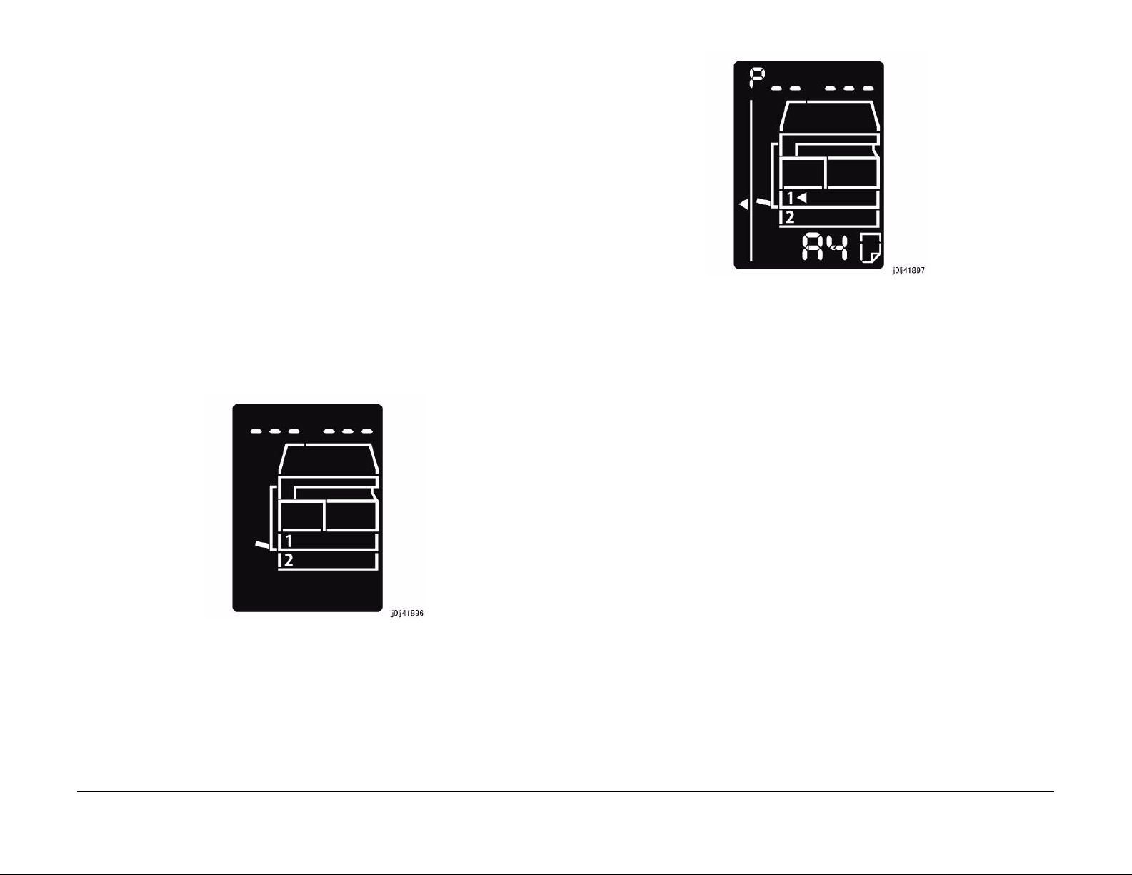
(1) Enter the System Administrator Mode.
i. Press the [Log In / Out] button and hold it down for 4 s or longer until the follow-
ing screen is displayed.
Figure 2 j0lj41897
(2) Load any one of A4 SEF, A4 LEF, Letter SEF, or Letter LEF into the Tray.
(3) Enter '202' at the Program Number and press the [Start] button.
(4) Enter '4' for [Error History Report] and press the [Start] button.
(5) Once printing has completed, press the [Log In / Out] button to exit from the Sy stem
Administrator Mode.
NOTE: When replacing parts that will incur cost to the customer, obtain the customer's
agreement before performing the replacement.
6. Repair all the secondary problems.
7. Perform TRIM Service.
ii. Use the keypad to enter the Passcode [11111 ]* 1 (5 '1 ' d ig it s) and pr ess the
[Start] button.
NOTE: *1: Default Value
iii. The Program Number input screen is displayed.
Initial Issue
WorkCentre 5021/5019
Figure 1 j0lj41896
1.2.3 When SM is requested, perform the following:
1. Check the copy quality.
Make several sheets of copies using the Test Chart (499T 00247), then check the quality
of the copies for problems.
2. Output the [Error History Report] and check the [System Fail History] and [Paper Jam History] in order to understand the machine status.
• For how to output the [Error History Report], refer to [1.2.2 When UM is reque sted,
perform the following:].
NOTE: When replacing parts that will incur cost to the customer, obtain the customer's
agreement before performing the replacement.
3. Perform TRIM Service.
1.2.4 Final Actions
1. Check overall operation/features.
2. Check the machine exterior and consumables.
3. Train the operator as required.
4. Complete the Service Log and Service Report.
08/2012
1-5
Service Call Procedure
1.2
Page 9

5. Keep the copy samples with the Service Log.
1.3 Detailed Contents of the Service Call
1.3.1 Initial Actions
1. Ask the operator(s) about the machine condition.
• How often and where do paper jams have been occurring recently
• How is the copy quality
2. Record the copy meter readings.
3. Inspect any error copies, then check the machine.
4. Check the print samples from previous service calls and the Service Log.
1.3.2 Checking Reproducibility of Problem
1. Check the problem status by performing the Level 1 Troubleshooting in [Chapter 2 Troubleshooting].
2. Perform the applicable Level 2 Troubleshooting FIP in [Chapter 2 Troubleshooting].
3. If there are no applicable items, troubleshoot by referring to [Chapter 7 BSD].
1.3.3 Checking Copy Quality
1. Make several sheets of copies using the Test Chart (499T 00247), then check the quality
of the copies.
1.3.4 TRIM Servicing
Perform TRIM servicing during a service call to maintain the machine performance.
1. Follow the TRIM Check List to perform the required TRIM items.
2. Check for parts that require periodical cleaning/replacement (consumables, parts) by
referring to the TRIM Chec List, the Periodic Replacement Parts/Consumables List, and
the Maintenance Report, and clean them if necessary. After a replacement, make sure
that you enter the CE Mode and use [HFSI Read / Clear] to clear the applicable
counter(s).
Service Call Procedure
1.3, 1.4
08/2012
1-6
Initial Issue
WorkCentre 5021/5019
Page 10

1.4 TRIM Check List
C: Perform checking. Clean, replace, or feed if necessary.
O: Always perform cleaning and checking.
*: Always perform replacement service at the specified interval.
Table 1
No. Servicing Items
1.1 Pre-servicing Check
(Check the machine
operation sound)
1.2 Pre-servicing Check
(Copy and print the
Test Chart)
2 Clean the interior of the
machine
(Clean the paper transport system)
3 Cleaning the IIT C • Clean the Platen Glass surface and the Platen
4 Clean the DADF C • Clean the Feed Roll, Nudger Roll, and Retard
5 S af ety Check O • M ake sure that the power plug is plugged in
6.1 Post-servicing check
(Copy Quality Check)
6.2 Post-servicing check
(Check the machine
operation)
6.3 Post-servicing check
(Check the meter)
Every
time Service Details
C • Activate the machine and check that abnormal
noise is not heard.
C • Make several sheets of copies using the Test
Chart (499T 00247), then check the quality of
the copies.
C • Clean any paper dust and toner residue in the
paper path and on the jam sensor.
• Especially, clean the operation section of the
operator carefully.
Cushion with the optical cleaning cloth.
• Clean the Reflector, back of the Platen Glass,
mirrors and lens with the optical cleaning cloth.
Roll with a cloth that has been wrung dry.
• Clean the DADF Platen Glass with the optical
cleaning cloth.
properly.
• Make sure that the power cords are not
cracked and no wires are exposed.
• Make sure that no extension cord with insufficient length or power cord outside the specification, such as an off-the-shelf power strip, is
being used.
• Make sure that a single socket does not have
multiple power plugs plugged into it.
C • Make several sheets of copies using the Test
Chart (499T 00247), then check if the quality
satisfies the specification.
C • Check the paper feed and abnormal noise.
C • Create the Service Log and Service Report.
1.5 Periodic Replacement Parts/Consumables List
When servicing, check the number of copies and number of fed sheets for the consumables
and parts that require periodical cleaning/replacement. Clean or replace them if necessary.
The history can be checked by printing the Maintenance Report or by checking the approriate
counter in [HFSI Read / Clear] in CE Mode (6.4.2.9 HFSI Read / Clear).
For the items that cannot be checked in CE Mode, clean or replace them according to the
replacement intervals (standard PV).
CAUTION
Do not place the imaging materials, such as the Toner and the Drum, in the car for a long time.
NOTE: Clean the Platen Glass with a Platen Wax Cleane r 499D 00194 (194D) every 10K
Feeds.
Table 1
Parts/Consumables
No
Name/PL No.
1 Tray 1 Feed No.
Tray 1 Feed Roll / Retard
Pad
(PL 9.2)
2 Tray 2 Feed No.
Tray 2 Feed Roll/Nudger
Roll/Retard Roll
(PL 10.3)
3 MSI Feed Count
MSI Feed Roll/MSI Nudger
Roll/MSI Retard Pad
(PL 13.3)
4 Fusing Unit
(PL 7.1)
5 BTR Unit
(PL 6.1)
6 Document Feed No.
DADF Feed Roll/Nudger
Roll
(PL 56.5)
DADF Retard Pad
(PL 56.13)
7 Toner Cartridge
(PL 8.1)
8 Drum Cartridge *1
(PL 8.1)
HFSI
[ChainLink]
950-803 50,000PV 1 Feed = 1 Count Up.
950-804 300,000PV 1 Feed = 1 Count Up.
950-802 50,000PV 1 Feed = 1 Count Up.
950-801 175,000PV 1 pass through the Fusing Unit
950-800 100,000PV 1 pass through the Fusing Unit
955-806 200,000PV Replace the Feed Roll,
- 9,000PV
950-807 343k cycle <Refer-
Replacement
Interval Check the counter
Replace both at the same
time.
Replace all 3 at the same
time.
Replace all 3 at the same
time.
Exit Sensor = 1 Count Up.
Exit Sensor = 1 Count Up.
Nudger Roll, and Retard Pad
at the same time.
NOTE: Clean the Platen Glass
with a Platen Wax Cleaner
499D 00914 (194D) every 10K
Feeds.
ence>75KPV*1@18PPM /
80KPV*1@20PPM
Initial Issue
WorkCentre 5021/5019
08/2012
1-7
Service Call Procedure
1.5
Page 11

*1: The maximum number of prints is a reference value under the condition of A4 LEF and simplex printing. Some specific conditions such as paper size, number of copies for a print job, etc.
might cause a serious deterioration of image quality before the time to replace the drum cartridge comes.
Service Call Procedure
1.5
08/2012
1-8
Initial Issue
WorkCentre 5021/5019
Page 12

2 Status Indicator RAPs
2.1 Introduction
2.1.1 How to Troubleshoot............................................................................................. 2-3
2.1.2 How to Switch the Error Code Display.................................................................. 2-3
2.1.3 Glossary..................................................... ........................................................... 2-4
2.2 Product FIP
2.2.1 Leve l 1 FIP
2.2.1.1 Level 1 FIP..................................................................... .................................... 2-7
2.2.2 Leve l 2 FIP
CHAIN 3
003-500/795 N-Up NG Out Of Range/ AMS NG Out Of Range..................................... 2-9
003-754 IPS Overrun ..................................................................................................... 2-9
003-942 Not-Supported Doc Size .................................................................................. 2-9
003-951 1Job Max Page Over....................................................................................... 2-9
003-963 APS NG Out Of Range.................................................................................... 2-9
003-972 EPC Memory Full . ............................................................................................ 2-9
003-973 Auto Rotation NG Out Of Range...................................................................... 2-9
CHAIN 4
004-345 HVPS Communication Error ......................... .... ......... .... .... .... ........... .... .... ....... 2-11
CHAIN 5
005-122 DADF Simplex/Side 1 Pre Regi Sensor On Jam ............................................. 2-13
005-123 DADF Simplex/Side 1 Regi Sensor On Jam.................................................... 2-13
005-125/145 DADF Regi Sensor Off Jam/ DADF Regi Sensor Off Jam on Inverting.... 2-13
005-131/132 DADF Invert Sensor On Jam on Inverting/ DADF Invert Sensor On Jam. 2-13
005-134/139 DADF Invert Sensor Off Jam on Inverting/ DADF Invert Sensor Off Jam. 2-14
005-135 DADF Side 2 Pre Regi Sensor On Jam........................................................... 2-14
005-136 DADF Side 2 Regi Sensor On Jam.................................................................. 2-14
005-147 DADF Pre Regi Sensor Off Jam on Inverting .................................................. 2-15
005-196 Size Mismatch Jam on No Mix-Size ................................................................ 2-15
005-197 Prohibit Combine Size Jam.............................................................................. 2-15
005-198/199 Too Short Size Jam/ Too Long Size Jam ...................................... .... ....... 2-15
005-210 DADF Download Fail ............................ .. .. .. .... .. ..... .. .... .. .. .. .. ....... .. .. .... .. .. .. .. ..... 2-15
005-275/280 DADF RAM Fail/ DADF EEPROM Fail ..................................................... 2-15
005-305 DADF Feeder Cover Interlock Open................................................................ 2-16
005-500 DADF Download Flash Write Error .................................................................. 2-16
005-907/908/913 DADF Pre Regi Sensor/DADF Regi Sensor/DADF Invert Sensor Static Jam
2-16
005-940 DADF No Original Fail ..................................................................................... 2-16
005-948 SS-Size Mismatch Jam on No Mix-size........................................................... 2-16
CHAIN 10
010-311 Fusing Unit Center Thermistor Defect ............................................................. 2-17
010-312 Fusing Unit Rear Thermistor Defect ................................................................ 2-17
010-320 Over Heat Temperature Fail ...... ....... .... .. .... .. .... ....... .. .... .. .... .. ....... .... .. .... .. ....... 2-17
010-327 Fusing Unit On Time Fail ................................................................................. 2-17
010-379 Fusing Unit Hot Not Ready Return Time Fail................................................... 2-18
010-392 NOHAD Fan Defect.......................................................................................... 2-18
010-602 Over Temp Cooling Mode..................................................................... .... .... .. . 2-18
CHAIN 16
016-500 Controller Download Flash Write Error ............................................................ 2-19
016-501 Controller Boot Flash Write Error..................................................................... 2-19
016-502 UI Panel Download Flash Write Error.............................................................. 2-19
016-570 No Response from USB-Host for Scan Job..................................................... 2-19
016-571 No Response from USB-Host for Print Job...................................................... 2-19
016-742/744 Download File Error/ Download File Check Sum Error............................. 2-19
016-749/799 HBPL or XPJL Syntax Error/ Print Instruction Fail .................................... 2-20
016-759 Copy Counter Full ............................................................................................ 2-20
016-776 Marker Code Detection Fail ............................................................................. 2-20
CHAIN 23
023-600 Held Down key Error (UI Panel)....................................................................... 2-21
CHAIN 24
024-910/911/915 Tray 1/Tray 2/MSI Paper Length Mismatch ....................................... 2-23
024-950/951/954 Tray 1/Tray 2/MSI No Paper.............................................................. 2-23
024-958/959/960 MSI/Tray 1/Tray 2 Paper Size Mismatch ........................................... 2-23
024-965 APS NG Unselected......................................................................................... 2-23
CHAIN 41
041-210/211 STM NVM Out-Of-Order/ STM NVM R/W Error........................................ 2-25
CHAIN 42
042-325/614 Main Motor Rotation Error/ Main Motor Rotation Warning........................ 2-27
CHAIN 45
045-310 Image Ready Error........................................................................................ ... 2-29
045-313 IOT Logic Fail................................................................................................... 2-29
CHAIN 61
061-321 ROS Motor Fail ............... .. ......... .. .... .. .... ....... .... .. .... .. ......... .. .... .. .... .. ......... .. .... . 2-31
061-325 No SOS Fail ............................................................................................ .... .. ... 2-31
CHAIN 62
062-277 DADF Communication Fail............................................................................... 2-33
062-311 IIT Software Logic Fail..................................................................................... 2-33
062-360 Carriage Position Fail....................................................................................... 2-33
062-371/380 Lamp Illumination Fail/ AGC Fail............................................................... 2-33
062-386 AOC Fail....................................................................................... .. ......... .. .... .. . 2-34
062-389 Carriage Over Run Fail (Scan End Side)......................................................... 2-34
062-396 CCD Cable Connection Fail................................................. .. .. .... .. .. ....... .. .... .. . 2-34
CHAIN 71
071-105 Regi Sensor On Jam (Tray 1). ......................................................................... 2-35
Initial Issue
WorkCentre 5021/5019
08/2012
2-1
Status Indic a tor RAPs
Page 13

CHAIN 72
072-102 Feed Out Sensor 2 On Jam............................................................................. 2-37
072-105 Regi Sensor On Jam (Tray 2).......................................................................... 2-37
072-210 Tray 2 Lift Up Fail..................................................... .... .. .... .. .. ....... .... .. .. .... .. ..... 2-37
072-212 Tray 2 Size Sensor Broken.............................................................................. 2-37
072-215 MCU-STM Communication Fail .................. .... .. ......... .... .. .... ....... .... .... .. .... ....... 2-37
CHAIN 75
075-135 Regi Sensor On Jam (MSI) . ............................................................................. 2-39
CHAIN 77
077-101 Regi Sensor Off Jam........................................................................................ 2-41
077-103 Fusing Unit Exit Sensor Off Jam (Long) .......................................................... 2-41
077-104 Fusing Unit Exit Sensor Off Jam (Short).......................................................... 2-41
077-106 Fusing Unit Exit Sensor On Jam . ..................................................................... 2-41
077-129 Regi Sensor On Jam (Duplex Wait)................................................................. 2-42
077-212 Tray Module Reset Fail............................................................................. .. ..... 2-42
077-300/301/305 Front Cover/Left Hand Cover/STM Cover Open................................ 2-42
077-900/901/904 Regi Sensor/Fusing Unit Exit Sensor/Feed Out Sensor 2 Static Jam 2-42
CHAIN 91
091-313 CRUM ASIC Communication Fail.................................................................... 2-43
091-401/402 Drum Cartridge Quality Life Over/ Drum Cartridge Life Over ................... 2-43
091-406/424 Drum Cartridge Normal Life Over/ Drum Cartridge Abnormal Life Over... 2-43
091-430 Drum Cartridge Life End ........ .... ......... .... .... .. .... ......... .... .. .... ......... .... .... .. .... ..... 2-43
091-440 Drum Cartridge Pre Near End.......................................................................... 2-43
091-441 Drum Cartridge Near End ............ ....... .... .. .... .... ....... .... .... .. .... ....... .... .... .. .... ..... 2-44
091-914 Drum CRUM Communication Fail.................................................................... 2-44
091-915/916 Drum CRUM ID Error/ Drum CRUM Market Identity Mismatch ................ 2-44
CHAIN 92
092-660/668 ATC Amplitude Fail/ ATC Average Fail..................................................... 2-45
092-661 Temperature Sensor Fail ....... .... ......... .... .. .... .... ......... .. .... .... ......... .. .... .... .... ..... 2-45
092-910 ATC Sensor Fail............................................................................ .... .. .... .... ..... 2-45
CHAIN 93
093-312 Toner Dispense Motor Rotation Fail................................................................ 2-47
093-400 Toner Near Empty............................................................................................ 2-47
093-406 Toner Pre Near Empty..................................................................................... 2-47
093-912 Toner Empty .................................................................................................... 2-47
093-956 Drum New CRU Installation Fail ..................... .. ....... .. .... .. .... .. ....... .. .... .. .... .. ..... 2-47
093-959 Drum New CRU Installation Fail Exceeds Thresholding Times....................... 2-47
CHAIN 95
095-910 No Drum Cartridge........................................................................................... 2-49
CHAIN 116
116-321 Controller Logic Fail......................................................................................... 2-51
116-323 Controller NVM Data Defect ............................................................................ 2-51
116-334 NVM Data Mismatch........................................................................................ 2-51
116-377 IIT Interrupt Time out ....................................................................................... 2-51
116-747 Invalid Page Margin ........................................................... .... ....... .... .. .... .. ....... 2-51
CHAIN 117
117-326 Controller Backup NVM Data Defect................................................................ 2-53
CHAIN 123
123-314 UI Panel Communication Fail........................................................................... 2-55
2.2.3 Other Failure FIP
2.2.3.1 AC Power FIP..................................................................................................... 2-57
2.2.3.2 +5VDC Power FIP.............................................................................................. 2-57
2.2.3.3 +24VDC Power FIP............................................................................................ 2-58
2.2.4 Generic FIP
2.2.4.1 Reflective Sensor Failure FIP............................................................................. 2-59
2.2.4.2 Permeable Sensor Failure FIP........................................................................... 2-59
2.2.4.3 Switch (Normal/Open) Failure FIP ..................................................................... 2-60
2.2.4.4 Solenoid/Clutch Not Energized Failure FIP........................................................ 2-60
2.2.4.5 Solenoid/Clutch Left Energized Failure FIP....................................................... 2-61
2.2.4.6 Motor Does Not Rotate Failure FIP.................................................................... 2-61
2.2.4.7 Motor Left Running Failure FIP.......................................................................... 2-62
2.2.4.8 NIP/RELEASE SOLENOID Not Energized Failure FIP...................................... 2-62
2.3 NET System Fault Check
2.3.1 No output is available, no data is printed .............................................................. 2-65
2.3.2 Printing can be performed but abnormally ........................................................... . 2-65
Status Indicator RAPs
08/2012
2-2
Initial Issue
WorkCentre 5021/5019
Page 14
2.1.1 How to Troubleshoot
Level 1 Troubleshooting:
• Level 1 Troubleshooting (Level 1 FIP) is the first step to diagnose a problem. Level 1 FIP
asks you whether any Fault Code and other problematic symptoms exist, guiding you to
Level 2 Troubleshooting or BSD to resolve the problem.
Level 2 Troubleshooting:
• Level 2 Troubleshooting is a diagnostic procedure of separating a problem by Fault Code,
document/paper jam and other problematic symptoms. Performing a FIP or an appropriate procedure in the Check Procedure enables you to discover causes of a problem in a
short period of time.
How to proceed with troubleshooting and Cautions:
• First, perform Level 1 FIP to categorize a problem. Second, proceed to an appropriate
Level 2 FIP or BSD to resolve the problem. To fi nd t he causes of the problem using FIP or
Check Procedure etc., thoroughly read the instructions and follow the procedure properly.
Sometimes, when two or more causes exist, they cannot be identified at once, so the
same FIP should be repeated. In this case, pay attention to a different judgment made in
the process of the same FIP.
• For source voltage related problems, such as being unable to power up the machine,
refer to 'Other Failure FIP' to proceed with the troubleshooting.
2.1.2 How to Switch the Error Code Display
When a problem has occurred in the machine, an Error Code or a Fault Code (Chain-Link) will
be displayed on the UI screen. When an Error Code is being displayed, you can perform the
following operation to switch the display to the Chain-Link number that correspond to that Error
Code. To repair, check the Chain-Link number and proceed with the appropriate FIP.
How to switch to the Chain-Link number
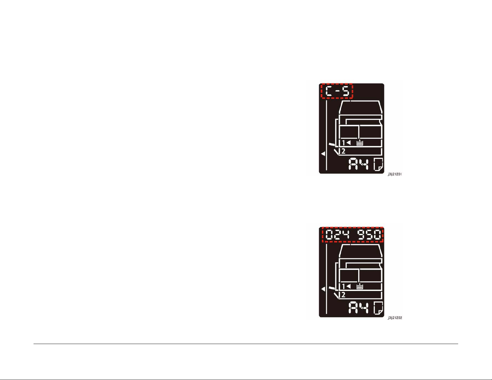
1. When a problem has occurred, the displayed Error Code will be flashing.
Figure 1 j0lj21201
• The Check Procedure for general electrical parts (Motor, Solenoid/Clutch, Switch, Sensor
etc.) may not be shown in each troubleshooting for some cases. In such cases, proceed
to troubleshoot by referring to 'Generic FIP'.
Initial Issue
WorkCentre 5021/5019
2. With the Error Code being displayed, press and hold down the [ID Card Copy] button on
the Control Panel.
• As long as the button is being pressed, the Chain-Link number will be displayed and
flashing.
Figure 2 j0lj21202
08/2012
2-3
Status Indic a tor RAPs
2.1.1, 2.1.2
Page 15

3. Releasing the [ID Card Copy] button returns the display to the Error Code.
2.1.3 Glossary
The following terminology are used throughout the t roubleshooting section. The meaning of
these terminology must be fully understood when performing problem analysis.
Common terms:
• Fault Code
This 6-digit code appears when the machine has found problems.
• Actuate (Deactuate)
To mechanically push (release) t he Actuator of the switch or the connected mechanical
linkage.
•Block
To place a sheet of document or paper on the photo sensor surface for detection.
• Check
To visually check for operation failure of parts such as relay or mechanical linkage, and
the failure status of the parts.
• Enter the CE Mode
To enter the CE Mode by following the procedure described in 'How to Enter/Exit the CE
Mode' of Chapter 6.
• Check the connection for short circuit
Turn the power OFF. Measure the resistance between the wire and the frame using the
ohm range of a tester.
• Check the connection for open circuit
Turn the power OFF. Measure the resistance between both ends of the wire using the
ohm range of a tester.
• Input Check [xxx-xxx]/Output Check [xxx-xxx]
To enter the Component Check by following the procedure described in 'How to Us e the
CE Mode' of Chapter 6.
• Analog Monitor [xxx-xxx]
To enter the Analog Monitor by following the procedure described in 'How to Use the CE
Mode' of Chapter 6.
• Check the voltage level
Status Indicator RAPs
2.1.2, 2.1.3
Voltage Level Range
+3.3VDC (H)
(L)
+5VDC (H)
(L)
+24VDC (H)
(L)
• PL 4.2
Refer to PL 4.2 in Chapter 5 Parts List.
• CH 6.2 Zone J4
08/2012
2-4
Table 1
+3.2 to +3.6VDC
0.0 to +1.0VDC
+4.8 to +5.4VDC
0.0 to +1.0VDC
+23.3 to +25.7VDC
0.0 to +3.0VDC
Initial Issue
WorkCentre 5021/5019
Page 16

Refer to Chain 6.2 Zone J4 in Chapter 7 BSD.
• REP 4.1.3
Refer to REP 4.1.3 in Chapter 4.
• ADJ 4.1.3
Refer to ADJ 4.1.3 in Chapter 4.
• Replace the parts in sequence
When it is impossible to analyze causes of a problem further, replace the parts in
sequence. The part with a higher replacement frequency or higher possibility of causing a
problem is listed first for replacement.
Initial Issue
WorkCentre 5021/5019
08/2012
2-5
Status Indic a tor RAPs
2.1.3
Page 17

Status Indicator RAPs
2.1.3
08/2012
2-6
Initial Issue
WorkCentre 5021/5019
Page 18

2.2.1.1 Level 1 FIP
Procedure
Ask the operator about the problem. Did the operator operate the machine correctly?
YN
Explain the correct way to operate the machine to the operator.
Output all jobs that are stored in the memory. Turn the power OFF and ON. Is the UI display
normal?
YN
Refer to [BS D (CH2.1)] and [2.2.3 Other Failure FIP] to repair the malfunction in UI display.
Check the Shutdown History. Refer to [6.4.2.1 Shutdown History] to display the Fault Code on
the UI. Is the Fault Code displayed on the UI?
YN
Refer to [Troubleshooting] in the User guide and repair the following errors.
• Problems With Hardware
• Problems With Image Quality
• Problems With Copy
• Problems W it h P ri n ter
• Problems With Scanner
• Problems With Network
• In Case of Paper Jam
• In Case of Document Jam
Proceed to Level 2 Troubleshooting and perform the applicable FIP.
Initial Issue
WorkCentre 5021/5019
08/2012
2-7
Status Indic a tor RAPs
2.2.1.1
Page 19

Status Indicator RAPs
2.2.1.1
08/2012
2-8
Initial Issue
WorkCentre 5021/5019
Page 20

003-500/795 N-Up NG Out Of Range/ AMS NG Out Of
Range
BSD-ON:-
[N-Up NG Out Of Range]
During 2-Up or 4-Up, the reduce/enlarge ration was not within the range of 25 to 400%.
[AMS NG Out Of Range]
003-951 1Job Max Page Over
BSD-ON:-
During Copy Job, the number of pages that can be scanned has been exceeded.
Cause/Action
Press [Stop] on the UI Panel and reduce the number of document pages.
During AMS (Auto Magnification Selection), the reduce/enlarge ration was not within the range
of 25 to 400%
Cause/Action
Press [Stop] on the UI Panel and change the settings.
003-754 IPS Overrun
BSD-ON:-
The IPS processing has overtook the Scan processing.
Cause/Action
This might be avoided by setting the R/E ratio to 99% or 101%. If this occurs frequently, obtain
the document from the User and contact the Support Department for assistance.
003-942 Not-Supported Doc Size
BSD-ON:-
During DADF Scan of a Copy Job, an unsupported document size was detected.
Cause/Action
1. Press [Stop] on the UI Panel.
2. Check the setting of the document size group.
3. Check whether the document size is a supported size.
4. If the document size is a supported size, the DADF might have malfunctioned. Refer to
following FIP to check the DADF.
• 005-196 (Size Mismatch Jam on No Mix-size)
• 005-948 (SS-Size Mismatch Jam on No Mix-size)
003-963 APS NG Out Of Range
BSD-ON:-
During Copy Job, when APS is selected, the image size obtained from document size x
reduce/enlarge ratio was detected to be larger than the largest Standard Paper Size.
Cause/Action
Press [Stop] on the UI Panel and change the settings.
003-972 EPC Memory Full
BSD-ON:-
During Copy Job, the EPC memory is filled up.
Cause/Action
Print out all the images that had been successfully scanned by the DADF so far and then perform the copy again for the documents (images) that were unable to be scanned.
003-973 Auto Rotation NG Out Of Range
BSD-ON:-
During Copy Job, the following conditions were met.
• Rotation is required.
• The length of the image obtained by document x reduce/enlarge ratio is longer than 297
mm.
Cause/Action
Press [Stop] on the UI Panel and change the reduce/enlarge ratio.
Initial Issue
WorkCentre 5021/5019
08/2012
2-9
Status Indic a tor RAPs
003-500/795, 003-951
Page 21

Status Indicator RAPs
003-500/795, 003-951
08/2012
2-10
Initial Issue
WorkCentre 5021/5019
Page 22

004-345 HVPS Communication Error
BSD-ON:CH9.2
Communication failure between the ESS/MCU PWB and the HVPS was detected.
Cause/Action
1. Turn the power OFF and ON.
2. Turn OFF the power and check the connection between the HVPS J500 and the ESS/
MCU PWB J402 for open circuit, short circuit, and poor contact.
3. If no problem is found, replace the following parts in sequence:
• HVPS (PL 18.1)
• ESS/MCU PWB (PL 18.1)
Initial Issue
WorkCentre 5021/5019
08/2012
2-11
Status Indic a tor RAPs
004-345
Page 23

Status Indicator RAPs
004-345
08/2012
2-12
Initial Issue
WorkCentre 5021/5019
Page 24

005-122 DADF Simpl ex/Side 1 Pre Regi Sensor On Jam
BSD-ON:CH5.4
• After Pre-Feed started for the first sheet (DADF Feed M otor On (CW)) in Simplex and
Duplex, the DADF Pre Regi Sensor did not turn ON within the specified time.
• After Pre-Feed started for the second sheet onwards (DADF Feed Motor On (CW)) in
Duplex, the DADF Pre Regi Sensor did not turn ON within the specified time.
Cause/Action
Check the following:
• Transportation failure due to foreign substance on the document path.
• The surface of the Feed Roll and Nudger Roll for foreign substances.
• The surface of the Feed Roll and Nudger Roll for wear.
• The DADF Pre Regi Sensor (Input Check [005-206]) for operation failure. (PL 56.14)
• The DADF Feed Clutch (Output Check [005-062]) for operation failure. (PL 56.7)
• The DADF Feed Motor (Output Check [005-008]) for operation failure. (PL 56.6)
• The Drive Gear for wear and damage.
If no problem is found, replace the DADF PWB. (PL 56.2)
005-123 DADF Simpl ex/Side 1 Regi Sensor On Jam
BSD-ON:CH5.5, CH5.4
005-125/145 DADF Regi Sensor Off Jam/ DADF Regi
Sensor Off Jam on Inverting
BSD-ON:CH5.5, CH5.4
[DADF Regi Sensor Off Jam]
After the DADF Pre Regi Sensor turned OFF at Scan operation, the DADF Regi Sensor did not
turn OFF within the specified time.
[DADF Regi Sensor Off Jam on Inverting]
After the DADF Pre Regi Sensor turned OFF at Invert operation, the DADF Regi Sensor did
not turn OFF within the specified time.
Cause/Action
Check the following:
• Transportation failure due to foreign substance on the document path.
• The surface of the Regi Roll, Out Roll, and Exit Roll for foreign substances.
• The surface of the Regi Roll, Out Roll, and Exit Roll for wear.
• The DADF Regi Sensor (Input Check [005-110]) for operation failure. (PL 56.14)
• The DADF Pre Regi Sensor (Input Check [005-206]) for operation failure. (PL 56.14)
• The DADF Feed Motor (Output Check [005-008]) for operation failure. (PL 56.6)
• The Drive Gear for wear and damage.
If no problem is found, replace the DADF PWB. (PL 56.2)
The DADF Regi Sensor does not turn ON within the specified time after the DADF Pre Regi
Sensor On.
Cause/Action
Check the following:
• Transportation failure due to foreign substance on the document path.
• The surface of the Takeaway Roll and Regi Roll for foreign substances.
• The surface of the Takeaway Roll and Regi Roll for wear.
• The DADF Regi Sensor (Input Check [005-110]) for operation failure. (PL 56.14)
• The DADF Pre Regi Sensor (Input Check [005-206]) for operation failure. (PL 56.14)
• The DADF T/A Clutch (Output Check [005-098]) for operation failure. (PL 56.7)
• The DADF Feed Motor (Output Check [005-008]) for operation failure. (PL 56.6)
• The Drive Gear for wear and damage.
If no problem is found, replace the DADF PWB. (PL 56.2)
Initial Issue
WorkCentre 5021/5019
08/2012
005-131/132 DADF Invert Sensor On Jam on Inverting/
DADF Invert Sensor On Jam
BSD-ON:CH5.5, CH5.4
[DADF Invert Sensor On Jam on Inverting]
After the DADF Regi Sensor turned ON at Invert operation, the DADF Invert Sensor did not
turn ON within the specified time.
[DADF Invert Sensor On Jam]
After the DADF Regi Sensor turned ON in the Scan operation, the DADF Invert Sensor did not
turn ON within the specified time.
Cause/Action
Check the following:
• Transportation failure due to foreign substance on the document path.
Status Indic a tor RAPs
2-13
005-122, 005-125/145
Page 25

• The surface of the Out Roll for foreign substances.
• The surface of the Out Roll for wear.
• The DADF Invert Sensor (Input Check [005-211]) for operation failure. (PL 56.10)
• The DADF Regi Sensor (Input Check [005-110]) for operation failure. (PL 56.14)
• The DADF Feed Motor (Output Check [005-008]) for operation failure. (PL 56.6)
• The Drive Gear for wear and damage.
If no problem is found, replace the DADF PWB. (PL 56.2)
005-134/139 DADF Invert Sensor Off Jam on Inverting/
DADF Invert Sensor Off Jam
BSD-ON:CH5.5, CH5.4
[DADF Invert Sensor Off Jam on Inverting]
During the Invert operation where there is a next document, after the DADF Regi Sensor
turned OFF, the DADF Invert Sensor did not turn OFF within the specified time.
[DADF Invert Sensor Off Jam]
005-135 DADF Side 2 Pre Regi Sensor On Jam
BSD-ON:CH5.4, CH5.5
After the DADF Feed Motor started the reverse rotation at Invert operation, the DADF Pre Regi
Sensor did not turn ON within the specified time.
Cause/Action
Check the following:
• Transportation failure due to foreign substance on the document path.
• The surface of the Exit Roll for foreign substances.
• The surface of the Exit Roll for wear
• The DADF Pre Regi Sensor (Input Check [005-206]) for operation failure. (PL 56.14)
• The DADF Feed Motor (Output Check [005-048]) for operation failure. (PL 56.6)
• The Exit Pinch Roll for operation failure (including for the operation failure of the Exit Nip
Release Solenoid (Output Check [005-072])). (PL 56.7)
• The Drive Gear for wear and damage.
If no problem is found, replace the DADF PWB. (PL 56.2)
During the Simplex and Duplex Scan operation, after the DADF Regi Sensor turned OFF, the
DADF Invert Sensor did not turn OFF within the specified time.
Cause/Action
Check the following:
• Transportation failure due to foreign substance on the document path.
• The surface of the Out Roll and Exit Roll for foreign substances.
• The surface of the Out Roll and Exit Roll for wear.
• The DADF Invert Sensor (Input Check [005-211]) for operation failure. (PL 56.10)
• The DADF Regi Sensor (Input Check [005-110]) for operation failure. (PL 56.14)
• The DADF Feed Motor (Output Check [005-008]) for operation failure. (PL 56.6)
• The Exit Pinch Roll for operation failure (including for the opera tion failure of the Exit Nip
Release Solenoid (Output Check [005-072])). (PL 56.7)
• The Drive Gear for wear and damage.
If no problem is found, replace the DADF PWB. (PL 56.2)
Status Indicator RAPs
005-131/132, 005-135
005-136 DADF Side 2 Regi Sensor On Jam
BSD-ON:CH5.5, CH5.4
After the DADF Pre Regi Sensor turned ON at Invert operation, the DADF Regi Sensor did not
turn ON within the specified time.
Cause/Action
Check the following:
• Transportation failure due to foreign substance on the document path.
• The surface of the Exit Roll, Takeaway Roll, and Regi Roll for foreign substances.
• The surface of the Exit Roll, Takeaway Roll, and Regi Roll for wear.
• The DADF Regi Sensor (Input Check [005-110]) for operation failure. (PL 56.14)
• The DADF Pre Regi Sensor (Input Check [005-206]) for operation failure. (PL 56.14)
• The DADF Feed Motor (Output Check [005-008]) for operation failure. (PL 56.6)
• The DADF T/A Clutch (Output Check [005-098]) for operation failure. (PL 56.7)
• The Exit Pinch Roll for operation failure (including for the operation failure of the Exit Nip
Release Solenoid (Output Check [005-072])). (PL 56.7)
• The Drive Gear for wear and damage.
If no problem is found, replace the DADF PWB. (PL 56.2)
08/2012
2-14
WorkCentre 5021/5019
Initial Issue
Page 26

005-147 DADF Pre Regi Sensor Off Jam on Inverting
BSD-ON:CH5.4, CH5.5
Cause/Action
Explain to the User that Mixed Size is not supported.
After the DADF Feed Motor started the reverse rotation at Invert operation, the DADF Pre Regi
Sensor did not turn OFF within the specified time.
Cause/Action
Check the following:
• Transportation failure due to foreign substance on the document path.
• The surface of the Exit Roll, Takeaway Roll, Regi Roll, and Out Roll for foreign substances.
• The surface of the Exit Roll, Takeaway Roll, Regi Roll, and Out Roll for wear.
• The DADF Pre Regi Sensor (Input Check [005-206]) for operation failure. (PL 56.14)
• The DADF Feed Motor (Output Check [005-048/ 008] (CCW/CW)) for operation failure.
(PL 56.6)
• The Exit Pinch Roll for operation failure (including for the opera tion failure of the Exit Nip
Release Solenoid (Output Check [005-072])). (PL 56.7)
• The Drive Gear for wear and damage.
If no problem is found, replace the DADF PWB. (PL 56.2)
005-196 Size Mismatch Jam on No Mix-Size
BSD-ON:CH5.4, CH5.2
The 2nd sheet or later of the document was detected to be of a different size conpared to the
1st sheet (the length of the document's 2nd sheet or later in SS direction is longer).
005-198/199 Too Short Size Jam/ Too Long Size Jam
BSD-ON:CH5.4, CH5.2
[Too Short Size Jam]
It was detected that the document length in Slow Scan direction is shorter than the specifications (Simpex: 85 mm, Duplex: 110 mm).
[Too Long Size Jam]
It was detected that the document length in Slow Scan direction is at the specifications (Simpex: 1275 mm, Duplex: 480.1 mm) or longer.
Cause/Action
Check the size of the document that was fed by the user. If it is within the permitted length for
DADF transport, check the following:
• The DADF Pre Regi Sensor (Input Check [005-206]) for operation failure. (PL 56.14)
• The Document Tray Size Sensor 1/2 (Input Check [005-221/222]) for operation failure.
(PL 56.11)
If no problem is found, replace the DADF PWB. (PL 56.2)
005-210 DADF Download Fail
BSD-ON:CH3.1
Cause/Action
1. Check the size of the document that was fed by the User.
2. If the error is not cleared, check the following:
• The DADF Pre Regi Sensor (Input Check [005-206]) for operation failure. (PL 56.14)
• The Document Tray Size Sensor 1/2 (Input Check [005-221/222]) for operation failure.
(PL 56.11)
3. If no problem is found, replace the DADF PWB. (PL 56.2)
005-197 Prohibit Combine Size Jam
BSD-ON:CH5.4
A Mixed Size document was detected.
Initial Issue
WorkCentre 5021/5019
When the IISS starts up (including at Power ON/Sleep recovery), it was detected that the
DADF is in Download Mode.
Cause/Action
Perform the DADF software download.
005-275/280 DADF RAM Fail/ DADF EEPROM Fail
BSD-ON:CH3.1
[DADF RAM Fail]
The DADF PWB RAM failed during the Read/Write operation. (At Power ON)
[DADF EEPROM Fail]
08/2012
2-15
005-147, 005-198/199
Status Indic a tor RAPs
Page 27

Write failure to DADF EEPROM or communication failure with EEPROM was detected.
Cause/Action
1. Turn the power OFF and ON.
2. If the problem persists, replace the DADF PWB. (PL 56.2)
• DADF Invert Sensor (Input Check[005-211]) (PL 56.10)
3. If no problem is found, replace the DADF PWB. (PL 56.2)
005-940 DADF No Original Fail
BSD-ON:CH5.1
It was detected that the document was pulled out during document feed.
005-305 DADF Feeder Cover Interlock Open
BSD-ON:CH5.1
The DADF Feeder Cover Interlock Switch was opened during DADF operation.
Cause/Action
1. Check the DADF Feeder Cover for mismatch.
2. Check the DADF Feeder Cover Interlock Switch (Input Check [005-212]) for operation
failure.
(PL 56.6)
3. If no problem is found, replace the DADF PWB. (PL 56.2)
005-500 DADF Download Flash Write Error
BSD-ON:CH3.1
Failed to write into the Flash ROM during DAFD Download.
Cause/Action
1. Turn the power OFF and ON.
2. If the problem persists, replace the following parts in sequence:
• DADF PWB (PL 56.2)
• ESS/MCU PWB (PL 18.1)
005-907/908/91 3 DADF Pre Regi Sensor/DADF Regi
Sensor/DADF Invert Sensor Static Jam
BSD-ON:CH5.4, CH5.5
Cause/Action
Reload the document.
005-948 SS-Size Mismatch Jam on No Mix-size
BSD-ON:CH5.4, CH5.2
In No Mix mode, it was detected that a document with a shorter size in Slow Scan (SS) direction was transported from the DADF.
Cause/Action
1. Check the size of the document that was fed by the User.
2. If the error is not cleared, check the following:
• The DADF Pre Regi Sensor (Input Check [005-206]) for operation failure. (PL 56.14)
• The Document Tray Size Sensor 1/2 (Input Check [005-221/222]) for operation failure.
(PL 56.11)
3. If no problem is found, replace the DADF PWB. (PL 56.2)
Paper was detected by the applicable sensor at Power ON, Feeder Cover Interlock Close, or
DADF Open Sensor Close.
Cause/Action
1. Check the applicable sensor for remaining paper, the Actuator for return failure, contamination on sensor, and etc.
2. Check the applicable sensor for operation failure.
• DADF Pre Regi Sensor (Input Check[005-206]) (PL 56.14)
• DADF Regi Sensor (Input Check[005-110]) (PL 56.14)
Status Indicator RAPs
005-275/280, 005-940
08/2012
2-16
Initial Issue
WorkCentre 5021/5019
Page 28

010-311 Fusing Unit Center Thermistor Defect
BSD-ON:CH10.2
010-320 Over Heat Temperature Fail
BSD-ON:CH10.2, CH10.1
An open circuit abnormality (the AD value of the STS is equivalent to the open circuit value) of
the Heat Roll Center Thermistor was detected.
Procedure
Turn OFF the power and disconnect the Heat Roll Center Thermistor connector P/J600. Measure the resistance between the Heat Roll Center Thermistor J600 pin-1 and J600 pin-2. Is
the resistance infinite?
YN
Reconnect the connector P/J600 and measure the resistance between the ESS/MCU
PWB J403 pin-1 and J403 pin-2. Is the resistance infinite?
YN
Replace the ESS/MCU PWB. (PL 18.1)
Check the following connections for open circuits and poor contacts.
• Between ESS/MCU PWB J403-1 and Heat Roll Center Thermistor P600-4
• Between ESS/MCU PWB J403-2 and Heat Roll Center Thermistor P600-3
Replace the Fusing Unit. (PL 7.1)
010-312 Fusing Unit Rear Thermistor Defect
BSD-ON:CH10.2
An open circuit abnormality (the AD value of the STS is equivalent to the open circuit value) of
the Heat Roll Rear Thermistor was detected.
Procedure
Turn OFF the power and disconnect the Heat Roll Rear Thermistor connector P/J600. Measure the resistance between the Heat Roll Rear Thermistor J600 pin-3 and J600 pin-4. Is the
resistance infinite?
YN
Reconnect the connector P/J600 and measure the resistance between the ESS/MCU
PWB J403 pin-3 and J403 pin-4. Is the resistance infinite?
YN
Replace the ESS/MCU PWB. (PL 18.1)
Check the following connections for open circuits and poor contacts.
• Between ESS/MCU PWB J403-3 and Heat Roll Rear Thermistor P600-2
• Between ESS/MCU PWB J403-4 and Heat Roll Rear Thermistor P600-1
A high temperature error was detected at the Center Thermistor (245 degrees C or higher) or
the Rear Thermistor (270 degrees C or higher).
NOTE: To clear this Fail, first remove the cause, next clear the value of NVM [744-040] (Over
Heat T emp Fail) to '0', and then turn the power OFF then ON. The relationship between the displayed value and the Thermistor that detected the high temperature error is as follows:
•0: Normal
• 1: High Temperature Error of Heat Roll Center Thermistor
• 2: High Temperature Error of Heat Roll Rear Thermistor
Cause/Action
Check the following:
• The Center Thermistor or the Rear Thermistor for dropped parts, sensor contamination,
and foreign substances blocking the sensor.
• The Heat Roll for wound up, stuck paper.
• The Heat Roll Center Thermistor (Analog Monitor [010-050]) for operation failure.
• The Heat Roll Rear Thermistor (Analog Monitor [010-051]) for operation failure.
• The Heater Rod for operation failure.
If no problem is found, replace the following parts in sequence:
• Fusing Unit (PL 7.1)
• LVPS (PL 18.1)
• ESS/MCU PWB (PL 18.1)
010-327 Fusing Unit On Time Fail
BSD-ON:CH10.2, CH10.1
Any of the following was detected:
• The Heater Rod did not turn OFF within the specified time after the Heater Rod On.
• After power ON, the temperature of the Fusing Unit does not reach the specified value
within the specified time.
Cause/Action
Check the following:
Replace the Fusing Unit. (PL 7.1)
Initial Issue
WorkCentre 5021/5019
• The Heater Rod for operation failure.
• The connection between the LVPS J511 and the Fusing Unit P10 for open circuit and
poor contact
• The Center Thermistor for dropped parts, sensor contamination, and foreign substances
blocking the sensor.
• The Heat Roll for wound up, stuck paper.
08/2012
2-17
Status Indic a tor RAPs
010-311, 010-320
Page 29

If no problem is found, replace the following parts in sequence:
• Fusing Unit (PL 7.1)
• LVPS (PL 18.1)
• ESS/MCU PWB (PL 18.1)
010-379 Fusing Unit Hot Not Ready Return Time Fail
BSD-ON:CH10.2, CH10.1
The time taken to recover from High Temperature Not Ready state has exceeded the specified
time.
Cause/Action
1. Turn the power OFF and ON.
2. Turn OFF the power and check the following:
• The Fusing Unit for improper installation.
• The connection between the Fusing Unit P10 and the LVPS J511 for open circuit,
short circuit, and poor contact.
• The connection between the Fusing Unit P600 and the ESS/ MCU PWB J403 for
open circuit, short circuit, and poor contact.
• The connection between the ESS/MCU PWB J401 and the LVPS J513 for open cir-
cuit, short circuit, and poor contact.
• The Heat Roll for wound up, stuck paper.
3. If the problem persists, replace the following parts in sequence:
• Fusing Unit (PL 7.1)
• LVPS (PL 18.1)
• ESS/MCU PWB (PL 18.1)
010-602 Over Temp Cooling Mode
BSD-ON:CH10.2
Unable to print because the temperature in the machine has risen above the specification
value.
Cause/Action
Wait until the temperature in the machine has dropped.
010-392 NOHAD Fan Defect
BSD-ON:CH10.3
NOHAD Fan failure was detected. When the NOHAD Fan Fail signal indicating an abnormality
of the Fan was monitored at the specified time interval, it was found to have failed the specified
number of times or higher in a row.
Cause/Action
1. Check the NOHAD Fan (Output Check [042-002]) for operation failure. (PL 4.1)
2. Check the NOHAD Fan for foreign substances.
3. If no problem is found, replace the ESS/MCU PWB. (PL 18.1)
Status Indicator RAPs
010-327, 010-602
08/2012
2-18
Initial Issue
WorkCentre 5021/5019
Page 30

016-500 Controller Download Flash Write Er ror
BSD-ON:-
Unable to write the Download File of Controller Main into the Flash ROM.
Cause/Action
1. Turn the power OFF and ON.
(If the contents of the Flash ROM is corrupted, the machine will boot up in Emergency
Boot Download mode after Power ON.)
2. If the problem persists, replace the ESS/MCU PWB. (PL 18.1)
Cause/Action
1. Press [Stop] on the UI Panel.
2. Check the connection of the USB Cable between this machine and the PC.
3. Check the status (is it powered OFF, frozen, etc.) of the PC.
016-571 No Response from USB-Host for Print Job
BSD-ON:CH3.2
When any of the following has occurred as USB Print or Download data interpretation is in
progress.
016-501 Controller Boot Flash Write Error
BSD-ON:-
Unable to write the Download File of Controller Boot into the Flash ROM.
Cause/Action
1. Turn the power OFF and ON.
2. If the problem persists, replace the ESS/MCU PWB. (PL 18.1)
016-502 UI Panel Download Flash Write Error
BSD-ON:CH2.1
Unable to write the Download File of UI Panel into the Flash ROM.
Cause/Action
1. Turn the power OFF and ON.
2. If the problem persists, replace the following parts in sequence:
• ESS/MCU PWB (PL 18.1)
•UI PWB (PL 1.6)
016-570 No Response from USB-Host for Scan Job
BSD-ON:CH3.2
When any of the following has occurred as Scan to PC (USB) is in progress.
• The command from the PC was disrupted for 2 minutes.
• The machine has detected a communication error with the USB Device.
• The sending of commands to the PC remained uns uccessful even when 500 ms has
passed.
NOTE: This Fault will clear automatically. (It will not be displayed on the UI Panel)
Cause/Action
1. Check the connection of the USB Cable between this machine and the PC.
2. Check the status (is it powered OFF, frozen, etc.) of the PC.
016-742/744 Download File Error/ Download File Check
Sum Error
BSD-ON:-
[Download File Error]
It was detected that there is an error with either the file format of the Download File, the Device
Identifier, the Device Serial Number, or the Target Device Character String.
[Download File Check Sum Error]
The Download File checksum error was detected.
Cause/Action
1. Turn the power OFF and ON.
2. Install a firmware with the correct version.
• The command from the PC was disrupted for 5 seconds.
• The machine has detected a communication error with the USB Device.
• The sending of commands to the PC remained uns uccessful even when 500 ms has
passed.
(The timeout time is the time calculated from the size of the data being sent only when
sending image data.)
Initial Issue
WorkCentre 5021/5019
08/2012
2-19
Status Indic a tor RAPs
016-500, 016-570
Page 31

016-749/799 HBP L or X PJL Syntax Error/ Print Instruction
Fail
BSD-ON:-
[HBPL or XPJL Syntax Error]
When the Print Job data interpretation is in progress, an illegal command that cannot be
ignored was received from the Client driver.
[Print Instruction Fail]
During the Print Job, the Job cannot be executed with the specified combination of print parameters (Stored File Size, Paper Size, Paper Tray, Duplex Settings, Output Tray, and etc.).
NOTE: During Continuous Print, this error will not occur until the paper that immediately precedes the paper where the applicable image is supposed to be printed on has been output successfully.
Cause/Action
1. Press [Stop] on the UI Panel.
2. Check whether the Printer Driver that is being used is the correct one.
3. Check whether the specified print parameters are correct.
016-759 Copy Counter Full
BSD-ON:-
During Multi Account Mode, any of the following has occurred:
016-776 Marker Code Detection Fail
BSD-ON:-
During Copy Job or Print Job, when expanding only up to the size that was specified at the
expansion, the End Code cannot be found in the compressed data.
NOTE: Before the occurrence of this fail, there are cases where [045-310 Image Ready Error]
would occur first.
NOTE: During Continuous Print, this error will not occur until the paper that immediately precedes the paper where the applicable image is supposed to be printed on has been output successfully.
Cause/Action
1. Turn the power OFF and ON.
2. If the problem reoccurs, determine whether it is caused by the Copy document or the Print
data and contact the Support Department for assistance.
• The general user that is logged in has reached the alotted maximum print count.
• A general user that has reached the alotted maximum print count has logged in.
Cause/Action
1. Press [Stop] on the UI Panel.
2. Clear the count for the user.
Status Indicator RAPs
016-749/799, 016-776
08/2012
2-20
Initial Issue
WorkCentre 5021/5019
Page 32

023-600 Held Down key Error (UI Panel)
BSD-ON:CH2.1
Any key on the UI Panel has been pressed and held down for 1 minute or longer.
Cause/Action
Check whether any key on the UI Panel is pressed and held down.
Initial Issue
WorkCentre 5021/5019
08/2012
2-21
Status Indic a tor RAPs
023-600
Page 33

Status Indicator RAPs
023-600
08/2012
2-22
Initial Issue
WorkCentre 5021/5019
Page 34

024-910/911/915 Tray 1/Tray 2/MSI Paper Length Mismatch
BSD-ON:CH8.3, CH8.1
The Paper Size for the applicable Tray is longer by 10.1 mm or more, or shorter by 13.1 mm or
more than the setting.
Cause/Action
Check the following:
• Transportation failure due to foreign substance on the document path.
• The surface of the Feed Roll, T/A Roll 2 (Tray 2), Regi. Roll, and Idler Roll of the applicable Tray for foreign substances.
• The surface of the Feed Roll, T/A Roll 2 (Tray 2), Regi. Roll, and Idler Roll of the applicable Tray for wear.
• The Regi Sensor (Input Check [071-105]) for operation failure. (PL 15.1)
• The Regi Clutch (Output Check [071-001]) for operation failure. (PL 15.1)
• The MSI Feed Clutch (Output Check [072-006]) for operation failure. (MSI) (PL 13.3)
• The BTR for contamination, wear, and transportation failure due to deterioration.
• The Drive Gear for wear and damage.
• Usage of out of spec paper.
• ESS/MCU PWB (Tray 1/MSI) (PL 18.1)
• STM PWB (Tray 2) (PL 10.6)
024-958/959/960 MSI/Tray 1/Tray 2 Paper Size Mismatch
BSD-ON:-
During Print Job, the paper size settings of the selected Tray is different from the paper size
specified for the Job.
Cause/Action
Change the paper settings of the selected Tray to the appropriate one.
024-965 APS NG Unselec ted
BSD-ON:-
During Copy Job, Print Job, and Report Job with APS settings, the Pa per Size and paper orientation (SEF/LEF) settings specified by the Job are different from the s ettings at Tray 1 and
Tray 2.
If no problems are found, replace the ESS/MCU PWB. (PL 18.1)
024-950/951/954 Tray 1/Tray 2/MSI No Paper
BSD-ON:CH7.2, CH7.3, CH7.4
Any of the following was detected:
• The paper in the applicable Tray has ran out.
(When the APS function of Tray 1 and Tray 2 is disabled)
• Although the paper in the applicable Tray was detected to have ran out, paper is not supplied from another Tray. (When the APS function of Tray 1 and Tray 2 is enabled)
Cause/Action
1. Load paper into the applicable Tray. (If this had occurred during AP S of Tray 1 or Tray 2,
load paper with the same settings as for the aplicable Tray into other than MSI.)
2. If the problem persists, check the following:
• The paper supply mechanism of the applicable Tray for damage and foreign s ub-
stances.
• The No Paper Sensor of the applicable Tray (Input Check [072-100/101/102]) for
operation failure. (PL 9.1, PL 10.3, PL 13.3)
• The No Paper Sensor of the applicable Tray for contamination, improper installation,
and Actuator operation failure.
3. If no problem is found, replace the following parts:
Cause/Action
Change the paper settings of the Tray to the appropriate one.
Initial Issue
WorkCentre 5021/5019
08/2012
2-23
Status Indic a tor RAPs
024-910/911/915 , 024-950/951/954
Page 35

Status Indicator RAPs
024-910/911/915 , 024-950/951/954
08/2012
2-24
Initial Issue
WorkCentre 5021/5019
Page 36

041-210/211 STM NVM Out-Of-Order/ STM NV M R/W Error
BSD-ON:CH3.2
[STM NVM Out-Of-Order]
The NVM of the STM is malfunctioning.
[STM NVM R/W Error]
Unable to perform NVM Read / Write for the STM.
Cause/Action
1. Turn the power OFF and ON.
2. If the problem persists, replace the STM PWB. (PL 10.6)
Initial Issue
WorkCentre 5021/5019
08/2012
2-25
Status Indic a tor RAPs
041-210/211
Page 37

Status Indicator RAPs
041-210/211
08/2012
2-26
Initial Issue
WorkCentre 5021/5019
Page 38

042-325/614 Main Motor Rotation Error/ Main Motor
Rotation Warning
BSD-ON:CH4.1
[Main Motor Rotation Error]
The Main Drive Motor revolution failure was detected. When the Lock Up (Main Drive Motor
Fail) signal of the Motor Drive output was monitored at the specified time interval after a certain
time has passed since the Main Drive Motor operation had started, it was found to have failed
5 times in a row.
[Main Motor Rotation Warning]
The Main Drive Motor revolution failure was detected. When the Lock Up (Main Drive Motor
Fail) signal of the Motor Drive output was monitored at the specified time interval after a certain
time has passed since the Main Drive Motor operation had started, it was found to have failed
2 times in a row.
Procedure
Enter the CE Mode and turn ON the Output Check [042-001] (Main Drive Motor). Does the
Main Drive Motor rotate?
YN
Check the power supply line (+24VDC, +5VDC) of the Main Drive Motor. Is the power
supply of the Main Drive Motor normal?
YN
Check the power supply circuit to the Main Drive Motor.
Turn OFF the power and check the following:
• The connection between the Main Drive Motor J202 and the ESS/MCU PWB J403
for open circuit, short circuit, and poor contact.
• The Drive Gear for wear, damage, and bearing blockage.
• The Main Drive Motor for loading.
If no problem is found, replace the following parts in sequence:
• Main Drive Motor (PL 3.1)
• ESS/MCU PWB (PL 18.1)
Press [Stop] and turn OFF the power. Check the connection between the Main Drive Motor
J202-8 and the ESS/MCU PWB J403-5 for open circuit, short circuit, and poor contact.
If no problem is found, replace the following parts in sequence:
• ESS/MCU PWB (PL 18.1)
• Main Drive Motor (PL 3.1)
Initial Issue
WorkCentre 5021/5019
08/2012
2-27
Status Indic a tor RAPs
042-325/614
Page 39

Status Indicator RAPs
042-325/614
08/2012
2-28
Initial Issue
WorkCentre 5021/5019
Page 40

045-310 Image Ready Error
BSD-ON:CH3.2
045-313 IOT Logic Fail
BSD-ON:-
Unable to send the Image-valid signal cannot within the specified time.
NOTE: When the attempt to expand the image has failed, [016-776 Marker Code Detection
Fail] occurs after the recover operation.
Cause/Action
1. Check the USB Cable (Local) for poor connection.
2. If no problem is found, replace the ESS/MCU PWB. (PL 18.1)
The IOT Software error was detected.
Cause/Action
1. Turn the power OFF and ON.
2. Install the correct version of the IOT firmware.
3. If the problem persists, replace the ESS/MCU PWB. (PL 18.1)
Initial Issue
WorkCentre 5021/5019
08/2012
2-29
Status Indic a tor RAPs
045-310, 045-313
Page 41

Status Indicator RAPs
045-310, 045-313
08/2012
2-30
Initial Issue
WorkCentre 5021/5019
Page 42

061-321 ROS Motor Fail
BSD-ON:CH6.4
061-325 No SOS Fail
BSD-ON:CH6.4
The number of rotation of the ROS Motor did not come within the standard range within the
specified time (5 s) after the ROS Motor On.
Cause/Action
1. Turn the power OFF and ON.
2. Check whether the Drum Cartridge is installed.
3. Check the ROS Motor (Output Check [061-001]) for operation failure.
4. Check the LD +5VDC power supply of the LD PWB J140 pin-8.
5. If no problem is found, replace the following parts in sequence:
• ROS Assembly (PL 2. 1)
• ESS/MCU PWB (PL 18.1)
After the detection of ROS Motor Ready (steady rotation), the SOS interval was detected to be
longer than the reference value 5 times in a row.
Cause/Action
1. Turn the power OFF and ON.
2. Check whether the Drum Cartridge is installed.
3. Turn OFF the power and check the connections between the ESS/MCU PWB J410,
J411 and the LD PWB J140, J160 for open circuits, short circuits, and poor contacts.
4. If no problem is found, replace the following parts in sequence:
• ROS Assembly (PL 2.1)
• ESS/MCU PWB (PL 18.1)
Initial Issue
WorkCentre 5021/5019
08/2012
2-31
Status Indic a tor RAPs
061-321, 061-325
Page 43

Status Indicator RAPs
061-321, 061-325
08/2012
2-32
Initial Issue
WorkCentre 5021/5019
Page 44

062-277 DADF Communi cation Fail
BSD-ON:CH3.1
062-371/380 Lamp Illumination Fail/ AGC Fail
BSD-ON:CH6.3, CH6.1
Transmission cannot be established between the ESS/MCU PWB and the DADF PWB.
Cause/Action
1. Turn the power OFF and ON.
2. Turn OFF the power and check the connections between the ESS/MCU PWB J421 and
the DADF PWB J751, J752 for open circuits, short circuits, and poor contacts.
3. If no problem is found, replace the following parts in sequence:
• DADF PWB (PL 56.2)
• ESS/MCU PWB (PL 18.1)
062-311 IIT Software Logic Fail
BSD-ON:-
A software error was detected at the ESS/MCU PWB.
Cause/Action
1. Turn the power OFF and ON.
2. Update the software version to the latest one.
3. If no problem is found, replace the ESS/MCU PWB. (PL 18.1)
062-360 Carriage Position Fail
BSD-ON:CH6.2
Any of the following was detected:
• An error with the count value of the Carriage Position Control.
• There is no Regi Sensor input during Carriage initialization.
• An error with the Regi Sensor detection position.
Cause/Action
Check the following:
• The Pre Regi Sensor (Input Check [062-212]) for operation failure. (PL 1.3)
• The Carriage Motor (Output Check [062-005/006] (Scan/Return)) for opera tion failure.
(PL 1.4)
• The Drive Belt and Drive Wire for slack and wear.
• The Carriage operation for mechanical loading.
If no problems are found, replace the ESS/MCU PWB. (PL 18.1)
[Lamp Illumination Fail]
Insufficient light from Lamp detected in CCD. (During white gradation correction/AGC before
Scan starts)
[AGC Fail]
Insufficient lamp brightness was detected when performing AGC.
Initial Actions
Check whether there is something blocking the light and check the Lamp, Lens, Mirror, and
White Color Correction Plate for deterioration or contamination.
Procedure
1. Turn ON the power and enter the Diag mode. Change the value for NVM [715-030] to '1'
and then perform [NVM Write].
2. A 3 or 4-digit number is displayed in the current value column.
3. Check the upper 1 or 2 digits, or the lower 2 digits using the following table and replace
the appropriate parts.
Sample Display
• 110 (3-digit display):
LED Lamp failure and LED Lamp Flexible Flat Cable is damaged or has poor contact.
(The first digit '1' in '1 10' is t he upper digit, which indicates the LED Lamp ('0' in '01' is
not displayed). The lower 2 digits '10' indicates the LED Lamp Flexible Flat Cable.)
• 1000 (4-digit display):
The LED Lamp Flexible Flat Cable is damaged or has poor contact.
(The first 2 digits '10' in '1000' are the upper digits, which indicates the LED Lamp
Flexible Flat Cable. The lower 2 digits '00' indicates that nothing is applicable (no
failures).)
NOTE: Perform IIT diagnostic and then call NVM [715-030] again (press the Change Settings button) to check the value (diagnostic result).
Table 1
Current value Component Name PL No.
00 Not applicable (No errors) 01 LED Lamp (LED Lamp PWB) PL 1.5
02 IIT Carriage PL 1.3
03 CCD Flexible Flat Cable PL 1.3
04 This value is not displayed 05 This value is not displayed -
Initial Issue
WorkCentre 5021/5019
08/2012
2-33
Status Indic a tor RAPs
062-277, 062-371/380
Page 45

Table 1
Current value Component Name PL No.
06 This value is not displayed 07 This value is not displayed 08 This value is not displayed 09 This value is not displayed 10 LED Lamp Flexible Flat Cable PL 1.5
4. After replacing the appropriate parts, again change the value for NVM [715-030] to '1' and
then perform 'NVM Write'.
5. Check that the current value column becomes '0'.
6. If the problem persists after performing the above procedure, check the following:
• Check for burnt out LED Lamp (DC330 [062-002]). (PL 1.5)
• Check the Flat Cable between the LED Lamp PWB J7002 and the IIT Carriage
J7001 for open circuits, short circuits, and poor contacts (especially, check whether
the Flat Cable was inserted in a skewed manner).
• Check the Flat Cable between the IIT Carriage J700 and the ESS/MCU PWB J420
for open circuits, short circuits, and poor contacts (especially, check whether the Flat
Cable was inserted in a skewed manner).
7. If no problem is found, replace the ESS/MCU PWB. (PL 18.1)
062-386 AOC Fail
BSD-ON:CH6.3
A CCD output error was detected when performing AOC.
Cause/Action
1. Turn ON the power and enter the Diag mode. Change the value for NVM [715-030] t o '1'
and then perform [NVM Write].
2. A 3 or 4-digit number is displayed in the current value column.
3. Check the upper 1 or 2 digits, or the lower 2 digits and replace the appropriate parts.
(For more information on display example and part selection, refer to Procedure 3 in 062-
371 FIP.)
NOTE: Perform IIT diagnostic and then call NVM [715-030] again (press the Change Settings button) to check the value (diagnostic result).
4. After replacing the appropriate parts, again change the value for NVM [715-030] to '1' and
then perform 'NVM Write'.
5. Check that the current value column becomes '0'.
6. If the problem persists after performing the above procedure, check the Flat Cable
between the IIT Carriage J700 and the ESS/MCU PWB J420 f or open circuits, short circuits, and poor contacts (especially, check whether the Flat Cable was inserted in a
skewed manner).
7. If no problem is found, replace the ESS/MCU PWB. (PL 18.1)
062-389 Carriage Over Run Fail (Scan End Side)
BSD-ON:CH6.2
The Carriage has overrun at the Scan End.
Cause/Action
Check the following:
• The Drive Belt and Drive Wire for slack and wear.
• The Carriage operation for mechanical loading.
• The Carriage Motor (Output Check [062-005/006] (Scan/Return)) for operation failure.
(PL 1.4)
• The IIT Regi. Sensor (Input Check [062-212]) for operation failure. (PL 1.3)
If no problems are found, replace the ESS/MCU PWB. (PL 18.1)
062-396 CCD Cable Connection Fail
BSD-ON:CH3.1
A CCD Flat Cable connection error was detected.
Cause/Action
1. Turn the power OFF and ON.
2. Turn OFF the power and check the Flat Cable between the IIT Carriage J700 and the
ESS/MCU PWB J420 for open circuits, short circuits, and poor contacts (especially,
check whether the Flat Cable was inserted in a skewed manner).
3. If no problem is found, replace the following parts in sequence:
• CCD Flexible Flat Cable (PL 1. 3)
• ESS/MCU PWB (PL 18.1)
Status Indicator RAPs
062-371/380, 062-389
08/2012
2-34
Initial Issue
WorkCentre 5021/5019
Page 46

071-105 Regi Sensor On Jam (Tray 1)
BSD-ON:CH8.3, CH4.1, CH8.1
During paper feed from Tray 1, the Regi Sensor did not turn ON within the specified time after
the Tray 1 Feed Clutch On.
Cause/Action
Check the following:
• The Regi Sensor (Input Check [071-105]) for operation failure. (PL 15.1)
• The Main Drive Motor (Output Check [042-001]) for operation failure. (PL 3.1)
• The Tray 1 Feed Clutch (Output Check [072-001]) for operation failure. (PL 9.1)
• The Feed Roll for contamination, wear, and transportation failure due to deterioration.
• The Drive Gear for wear and damage.
• A paper transportation failure due to foreign substances on the paper path.
• Usage of out of spec paper.
If no problems are found, replace the ESS/MCU PWB. (PL 18.1)
Initial Issue
WorkCentre 5021/5019
08/2012
2-35
Status Indic a tor RAPs
071-105
Page 47

Status Indicator RAPs
071-105
08/2012
2-36
Initial Issue
WorkCentre 5021/5019
Page 48

072-102 Feed Out Sensor 2 On Jam
BSD-ON:CH8.2, CH7.3
• STM PWB (PL 10.6)
During paper feed from Tray 2, the Feed Out Sensor 2 did not turn ON within the specified time
after the Tray 2 Feed Motor On.
Cause/Action
Check the following:
• The Feed Out Sensor 2 (Input Check [072-104]) for operation failure. (PL 10.5)
• The STM Take Away Motor (Output Check [072-004]) for operation failure. (PL 10.6)
• The STM T ake A way Roll Clutch (Output Check [072-003]) for operation failure. (PL 10.6)
• The Tray 2 Feed/Lift Up Motor (Output Check [072-002] (Feed)) for operation failure. (PL
10.3)
• The T/A Roll 2, Feed Roll, Nudger Roll, and Pinch Roll for transportation failure due to
contamination, wear, and deterioration.
• The LH Cover for improper latching.
• The Drive Gear for wear and damage.
• A paper transportation failure due to foreign substances on the paper path.
• Usage of out of spec paper.
If no problem is found, replace the STM PWB. (PL 10.6)
072-105 Regi Sensor On Jam (Tray 2)
BSD-ON:CH8.3, CH8.2
During paper feed from Tray 2, the Regi Sensor did not turn ON within the specified time after
the Feed Out Sensor 2 On.
072-210 Tray 2 Lift Up Fail
BSD-ON:CH7.3
Any of the following was detected:
• A Tray 2 Lifter error.
• A Tray 2 Paper Size detector component malfunction.
Cause/Action
Check the following:
• The Tray 2 Nudger Level Sensor (Input Check [072-103]) for operation failure. (PL 10.3)
• The Tray 2 Feed/Lift Motor (Output Check [072-005] (Lift Up)) for operation failure. (PL
10.3)
• The drive system between the Bottom Plate and the Tray 2 Feed/Lift Motor for operation
failure.
• The Tray for Paper misload
• The Tray for existence of objects other than Paper.
If no problem is found, replace the STM PWB. (PL 10.6)
072-212 Tray 2 Size Sensor Broken
BSD-ON:CH7.1
Abnormal output AD value from Tray 2 Paper Size Switch was detected.
Cause/Action
Check the following:
• The Regi Sensor (Input Check [071-105]) for operation failure. (PL 15.1)
• The STM Take Away Motor (Output Check [072-004]) for operation failure. (PL 10.6)
• The STM T ake A way Roll Clutch (Output Check [072-003]) for operation failure. (PL 10.6)
• The T/A Roll 2, Feed Roll, and Pinch Roll for transportation failure due to contamination,
wear, and deterioration.
• The Drive Gear for wear and damage.
• A paper transportation failure due to foreign substances on the paper path.
• Usage of out of spec paper.
If no problem is found, replace the following parts in sequence:
• ESS/MCU PWB (PL 18.1)
Initial Issue
WorkCentre 5021/5019
Cause/Action
Check the following:
• Broken link and damage at the bottom of the Tray
• The Actuator at the rear of the Tray for operation failure
• The Tray 2 Paper Size Switch (Analog Monitor [072-050], Output Check [072-105]) for
operation failure. (PL 10.1)
• The Tray for Paper misload
• The Tray for existence of objects other than Paper.
If no problem is found, replace the STM PWB. (PL 10.6)
072-215 MCU-STM Communication Fail
08/2012
2-37
Status Indic a tor RAPs
072-102, 072-105
Page 49

BSD-ON:CH3.2
Communication failure between the ESS/MCU PWB and the STM PWB was detected.
Cause/Action
1. Turn the power OFF and ON.
2. Turn OFF the power and check the connection between the ESS /MCU PWB J413 and
the STM PWB J541C for open circuit, short circuit, and poor contact.
3. If no problem is found, replace the following parts in sequence:
•STM PWB (PL 10.6)
• ESS/MCU PWB (PL 18.1)
Status Indicator RAPs
072-215
08/2012
2-38
Initial Issue
WorkCentre 5021/5019
Page 50

075-135 Regi Sensor On Jam (MSI)
BSD-ON:CH8.3, CH4.1, CH8.1
During paper feed from the MSI, the Regi Sensor did not turn ON within the specified time after
the MSI Feed Clutch On.
Cause/Action
Check the following:
• The Regi Sensor (Input Check [071-105]) for operation failure. (PL 15.1)
• The Main Drive Motor (Output Check [042-001]) for operation failure. (PL 3.1)
• The MSI Feed Clutch (Output Check [072-006]) for operation failure. (PL 13.3)
• The MSI Feed Roll and the MSI Nudger Roll for contamination, wear, and transportation
failure due to deterioration.
• The Drive Gear for wear and damage.
• A paper transportation failure due to foreign substances on the paper path.
• Usage of out of spec paper.
If no problems are found, replace the ESS/MCU PWB. (PL 18.1)
Initial Issue
WorkCentre 5021/5019
08/2012
2-39
Status Indic a tor RAPs
075-135
Page 51

Status Indicator RAPs
075-135
08/2012
2-40
Initial Issue
WorkCentre 5021/5019
Page 52

077-101 Regi Sensor O ff Jam
BSD-ON:CH8.3, CH4.1
077-104 Fusing Unit Exit Sensor Off Jam (Short)
BSD-ON:CH10.3, CH8.3, CH4.1, CH10.4
The Regi Sensor did not turn OFF within the specified time after the Regi Clutch On.
Cause/Action
Check the following:
• The Regi Sensor (Input Check [071-105]) for operation failure. (PL 15.1)
• The Main Drive Motor (Output Check [042-001]) for operation failure. (PL 3.1)
• The Regi Clutch (Output Check [071-001]) for operation failure. (PL 15.1)
• The Regi Roll and Pinch Roll for transportation failure due to contamination, wear, and
deterioration.
• The Transfer Unit for a decrease in the transportation force.
• The Drive Gear for wear and damage.
• A paper transportation failure due to foreign substances on the paper path.
• Usage of out of spec paper.
If no problems are found, replace the ESS/MCU PWB. (PL 18.1)
077-103 Fusing Unit Exit Sensor Off Jam (Long)
BSD-ON:CH10.3, CH4.1, CH10.4
After the Regi Sensor Off, the Fusing Unit Exit Sensor did not turn OFF within the specified
time.
Cause/Action
Check the following:
• The Fusing Unit Exit Sensor (Input Check [071-106]) for operation failure. (PL 7.1)
• The Main Drive Motor (Output Check [042-001]) for operation failure. (PL 3.1)
• The Invert Motor (Output Check [071-003] (Exit)) for operation failure.
(When Duplex is installed) (PL 17.1)
• The Exit Roll and Pinch Roll for transportation failure due to contamination, wear, and
deterioration.
• The Transfer Unit for a decrease in the transportation force.
• The Heat Roll for wound up, stuck paper.
• The Drive Gear for wear and damage.
• Usage of out of spec paper.
The time taken for the Fusing Unit Exit Sensor to turn from ON to OFF is shorter than the specified time.
Cause/Action
Check the following:
• The Fusing Unit Exit Sensor (Input Check [071-106]) for operation failure. (PL 7.1)
• The Regi Sensor (Input Check [071-105]) for operation failure. (PL 15.1)
• The Main Drive Motor (Output Check [042-001]) for operation failure. (PL 3.1)
• The Invert Motor (Output Check [071-003] (Exit)) for operation failure.
(When Duplex is installed) (PL 17.1)
• The Heat Roll for wound up, stuck paper.
• Usage of out of spec paper.
If no problems are found, replace the ESS/MCU PWB. (PL 18.1)
077-106 Fusing Unit Exit Sensor On Jam
BSD-ON:CH10.3, CH8.3, CH4.1
The Fusing Unit Exit Sensor did not turn ON within the specified time after the Regi Clutch On.
Cause/Action
Check the following:
• The Fusing Unit Exit Sensor (Input Check [071-106]) for operation failure. (PL 7.1)
• The Main Drive Motor (Output Check [042-001]) for operation failure. (PL 3.1)
• The Regi Clutch (Output Check [071-001]) for operation failure. (PL 15.1)
• The Fusing Unit Exit Chute for improper installation and deformation.
• The Transfer Unit for a decrease in the transportation force.
• The Drive Gear for wear and damage.
• The Heat Roll for wound up, stuck paper.
• A paper transportation failure due to foreign substances on the paper path.
• Usage of out of spec paper.
If no problems are found, replace the ESS/MCU PWB. (PL 18.1)
If no problems are found, replace the ESS/MCU PWB. (PL 18.1)
Initial Issue
WorkCentre 5021/5019
08/2012
2-41
Status Indic a tor RAPs
077-101, 077-104
Page 53

077-129 Regi Sensor On Jam (Duplex Wait)
BSD-ON:CH8.3, CH4.1, CH10.4
During the paper stop at the invert wait position at D uplex print, the Regi Sensor did not turn
ON within the specified time after the Duplex Clutch On.
077-300/301/305 Front Cover/Left Hand Cover/STM Cover
Open
BSD-ON:CH1.5, CH1.6
The applicable Cover Switch was detected to be open.
Cause/Action
Check the following:
• The Regi Sensor (Input Check [071-105]) for operation failure. (PL 15.1)
• The Main Drive Motor (Output Check [042-001]) for operation failure. (PL 3.1)
• The Invert Motor (Output Check [071-005] (Dup)) for operation failure. (PL 17.1)
• The Dupex Clutch (Output Check [071-002]) for operation failure. (PL 14.4)
• The Exit Roll, Duplex Roll 1, 2, and Pinch Roll for transportation failure due to contamination, wear, and deterioration.
• The Drive Gear and Belt for wear and damage.
• A paper transportation failure due to foreign substances on the paper path.
• Usage of out of spec paper.
If no problems are found, replace the ESS/MCU PWB. (PL 18.1)
077-212 Tray Module Reset Fail
BSD-ON:CH3.2
The Tray Module was detected to be reset.
Cause/Action
1. Turn the power OFF and ON.
2. Check voltages of the following pins:
•STM PWB J541C-5 (+5VDC)
•STM PWB J541C-8 (+24VDC)
3. Turn OFF the power and check the connection between the ESS /MCU PWB J413 and
the STM PWB J541C for open circuit, short circuit, and poor contact.
4. If no problem is found, replace the following parts in sequence:
•STM PWB (PL 10.6)
• ESS/MCU PWB (PL 18.1)
Cause/Action
1. Check the applicable Cover Switch for operation failure.
• Front Cover Switch (Input Check[071-301]) (PL 19.1)
• Front Cover Interlock Switch and L/H Cover Interlock Switch (Input Check[071-300])
(PL 19.1, PL 14.1)
• STM Left Cover Switch (Input Check[072-300]) (PL 10.4)
2. Check the applicable Cover Switch for damage and mismatch.
3. If no problem is found, replace the following parts:
• ESS/MCU PWB (Front Cover Open, L/H Cover Open) (PL 18.1)
• STM PWB (STM Left Cover Open) (PL 10.6)
077-900/901/904 Regi Sensor/Fusing Unit Exit Sensor/
Feed Out Sensor 2 Static Jam
BSD-ON:CH8.3, CH10.3, CH8.2
Paper was detected by the applicable sensor at Power ON, M/C Stop, or Interlock Close.
Cause/Action
1. Check the applicable sensor for remaining paper, the Actuator for return failure, contamination on sensor, and etc.
2. Check the applicable sensor for operation failure.
• Regi Sensor (Input Check[071-105]) (PL 15.1)
• Fusing Unit Exit Sensor (Input Check[071-106]) (PL 7.1)
• Feed Out Sensor 2 (Input Check[072-104]) (PL 10.5)
3. If no problem is found, replace the following parts:
• ESS/MCU PWB (Regi Sensor, Fusing Unit Exit Sensor) (PL 18.1)
• STM PWB (Feed Out Sensor 2) (PL 10.6)
Status Indicator RAPs
077-129, 077-300/301/305
08/2012
2-42
Initial Issue
WorkCentre 5021/5019
Page 54

091-313 CRUM ASIC Communi cation Fail
BSD-ON:CH9.1
Communication failure between the CRUM ASIC and the CPU was detected.
The CRUM ASIC has malfunctioned.
Cause/Action
1. Turn the power OFF and ON.
NOTE: If this resolves the problem, it is highly probable that the ESS/MCU PWB had misdetected due to external noise abnormal or noise caused by elect rical discharge in the
machine. Check for any noise source around the machine and check for any abnormal
electrical discharge, etc.
2. Turn OFF the power and check the following:
• The Drum CRUM PWB and Drum Cartridge CRUM connection terminals in the
Drum Cartridge for poor contact.
• The connection between the Drum Cartridge J615 and the Drum CRUM PWB JA
for open circuit, short circuit, and poor contact.
• The connection between the ESS/MCU PWB J426 and the Drum Cartridge P615
for open circuit, short circuit, and poor contact.
3. If no problem is found, replace the following parts in sequence:
• Drum Cartridge (PL 8.1)
• ESS/MCU PWB (PL 18.1)
091-401/402 Drum Cartridge Quality Life Over/ Drum
Cartridge Life Over
BSD-ON:CH9.1
[Drum Cartridge Quality Life Over]
091-406/424 Drum Cartridge Normal Life Over/ Drum
Cartridge Abnormal Life Over
BSD-ON:CH9.1
[Drum Cartridge Normal Life Over]
The operation guarantee period for the Drum Cartridge has ended.
(When Drum Hard Stop-less is enabled)
[Drum Cartridge Abnormal Life Over]
The Drum Cartridge is out of warranty and this could result in a malfunction of the machine.
(When Drum Hard Stop-less is enabled)
Cause/Action
Replace the Drum Cartridge. (PL 8.1)
091-430 Drum Cartridge Life End
BSD-ON:CH9.1
The Drum Cartridge must be replaced.
Cause/Action
Replace the Drum Cartridge. (PL 8.1)
091-440 Drum Cartridge Pre Near End
BSD-ON:CH9.1
The image quality guarantee period for the Drum Cartridge has ended.
(When Drum Hard Stop-less is enabled)
[Drum Cartridge Life Over]
When in Life Extension Mode, the Drum Cartridge was detected to be near the end of its
lifespan.
Cause/Action
Replace the Drum Cartridge. (PL 8.1)
Initial Issue
WorkCentre 5021/5019
08/2012
Preparation for replacing the Drum Cartridge is required.
Cause/Action
The Drum Cartridge needs to be replaced soon. Prepare a new Drum Cartridge.
Replace the Drum Cartridge as required. (PL 8.1)
2-43
091-313, 091-406/424
Status Indic a tor RAPs
Page 55

091-441 Drum Cartridge Near End
BSD-ON:CH9.1
The Drum Cartridge needs to be replaced soon.
Cause/Action
The Drum Cartridge needs to be replaced soon. Replace the Drum Car tridge as required. (PL
8.1)
091-914 Drum CRUM Communication Fail
BSD-ON:CH9.1
Communication failure with Drum CRUM was detected.
The CRUM ASIC has malfunctioned.
Cause/Action
1. Turn the power OFF and ON.
2. Turn OFF the power. Disconnect and reconnect the Drum Cartridge.
NOTE: If turning the power OFF and ON or removing and reinstalling the Drum Cartridge
resolves the problem, it is highly probable that the ESS/MCU PWB had misdetected due
to external noise abnormal or noise caused by electrical discharge in the machine. Check
for any noise source around the machine and check for any abnormal electrical discharge, etc.
3. Turn OFF the power and check the following:
• The Drum CRUM PWB and Drum Cartridge CRUM connection terminals in the
Drum Cartridge for poor contact.
• The connection between the Drum Cartridge J615 and the Drum CRUM PWB JA
for open circuit, short circuit, and poor contact.
• The connection between the ESS/MCU PWB J426 and the Drum Cartridge P615
for open circuit, short circuit, and poor contact.
4. If no problem is found, replace the following parts in sequence:
• Drum Cartridge (PL 8.1)
• ESS/MCU PWB (PL 18.1)
091-915/916 Drum CRUM ID Error/ Drum CRUM Market
Identity Mismatch
BSD-ON:CH9.1
[Drum CRUM ID Error]
The Drum CRUM ID error was detected.
[Drum CRUM Market Identity Mismatch]
The Drum CRUM region mismatch was detected.
Cause/Action
Replace it with the correct Drum Cartridge. (PL 8.1)
Status Indicator RAPs
091-441, 09 1-915/916
08/2012
2-44
Initial Issue
WorkCentre 5021/5019
Page 56

092-660/668 ATC Amplitude Fail/ ATC Average Fail
BSD-ON:CH9.3
092-910 ATC Sensor Fail
BSD-ON:CH9.3
[ATC Amplitude Fail]
The output amplitude of the ATC Sensor in the ATC (Automatic Toner Control) measurement is
small.
[ATC A verage Fail]
The average output value is not within the specified range in the ATC (Automatic Toner Control) measurement.
Cause/Action
1. Install a Toner Cartridge that contains Toner. Copy a Test Chart (499T 00247), etc. and
check whether the density has recovered.
2. Check the Toner Dispense Motor (Output Check [092-001]) for operation failure. (PL 8.2)
3. Check the Toner transport path for Toner blockage.
4. Check the connection between the ATC Sensor (Drum Cartridge) P6 15 and the ESS/
MCU PWB J409 for open circuit, short circuit, and poor contact.
5. If no problem is found, replace the following parts in sequence:
• Drum Cartridge (PL 8.1)
• ESS/MCU PWB (PL 18.1)
092-661 Temperature Sensor Fail
BSD-ON:CH9.4
The output value of the Temperature Sensor is not within the specification range.
The frequency at which the ATC Average Fail or the ATC Amplitude Fail has been occurring is
at the threshold value or higher.
NOTE: To clear this Fail, clear the value of NVM [752-059] (ATC Fail) or NVM [752-060] (ATC
Fail Continuous Count) to '0'. If the machine is not repaired back to norm al status, this Fa il will
occur again during the operation.
NOTE: Setting the NVM [752-005] (Dispense Mode) to '0' (Timer Disp) or '2' (ICDC Disp) will
prevent ATC related fail from occurring and enable you to use the M/C. However, this means
that the Toner density will not be controlled.
Cause/Action
1. Install a Toner Cartridge that contains Toner. Copy a Test Chart (499T 00247), etc. and
check whether the density has recovered.
2. Check the Toner Dispense Motor (Output Check [092-001]) for operation failure. (PL 8.2)
3. Check the Toner transport path for Toner blockage.
4. Check the connection between the ATC Sensor (Drum Cartridge) P615 and the ESS/
MCU PWB J409 for open circuit, short circuit, and poor contact.
5. Check for toner blockage within the Developer Unit.
6. If no problem is found, replace the following parts in sequence:
• Drum Cartridge (PL 8.1)
• ESS/MCU PWB (PL 18.1)
Cause/Action
1. Turn the power OFF and ON.
2. Check the connection between the HVPS J 500-1 and the ESS/MCU PW B J402-14 for
open circuit, short circuit, and poor contact.
3. If no problem is found, replace the following parts in sequence:
• HVPS (PL 18.1)
• ESS/MCU PWB (PL 18.1)
Initial Issue
WorkCentre 5021/5019
08/2012
2-45
Status Indic a tor RAPs
092-660/668, 092-910
Page 57

Status Indicator RAPs
092-660/668, 092-910
08/2012
2-46
Initial Issue
WorkCentre 5021/5019
Page 58

093-312 Toner Dispense Motor Rotation Fail
BSD-ON:CH9.3
093-912 Toner Empty
BSD-ON:CH9.3
Regardless of low usage of toner from Toner Cartridge, it was detected to be empty.
Cause/Action
Check the following:
• The Toner Cartridge for improper installation
• The Toner Dispense Motor (Output Check [092-001]) for operation failure. (PL 8.2)
• The Toner transport path for Toner blockage.
• The Drive Gear for wear and damage.
If no problem is found, replace the following parts in sequence:
• Toner Cartridge (PL 8.1)
• ESS/MCU PWB (PL 18.1)
093-400 Toner Near Empty
BSD-ON:CH9.3
The Toner Cartridge needs to be replaced soon.
Cause/Action
The Toner Cartridge needs to be replaced soon. Replace the Toner Cartridge as required. (PL
8.1)
The toner must to be replaced as it has ran out.
Cause/Action
Replace the Toner Cartridge. (PL 8.1)
093-956 Drum New CRU Installation Fail
BSD-ON:CH9.3
During the developing powder installation mode after installing the Drum Cartridge, the ATC
Measured Value is found to be abnormal. (Seal not removed)
Cause/Action
1. Remove the developing powder seal from the Drum Cartridge.
2. If the problem persists after removing the seal, replace the Drum Cartridge. (PL 8.1)
093-959 Drum New CRU Installation Fail Exceeds
Thresholding Times
BSD-ON:-
The number of developing powder installation mode executions has exceeded the upper limit.
Cause/Action
Replace it with the correct Drum Cartridge. (PL 8.1)
093-406 Toner Pre Near Empty
BSD-ON:CH9.3
Preparation for replacing the T oner Cartridge is required.
Cause/Action
The Toner Cartridge needs to be replaced soon. Prepare a new Toner Cartridge.
Replace the Toner Cartridge as required. (PL 8.1)
Initial Issue
WorkCentre 5021/5019
08/2012
2-47
Status Indic a tor RAPs
093-312, 093-912
Page 59

Status Indicator RAPs
093-312, 093-912
08/2012
2-48
Initial Issue
WorkCentre 5021/5019
Page 60

095-910 No Drum Cart ridge
BSD-ON:CH9.1
The Drum Cartridge cannot be detected.
Cause/Action
1. Turn the power OFF and ON.
2. Turn OFF the power and check the following:
• The Drum CRUM PWB and Drum Cartridge CRUM connection terminals in the
Drum Cartridge for poor contact.
• The connection between the Drum Cartridge J615 and the Drum CRUM PWB JA
for open circuit, short circuit, and poor contact.
• The connection between the ESS/MCU PWB J426 and the Drum Cartridge P615
for open circuit, short circuit, and poor contact.
3. If no problem is found, replace the following parts in sequence:
• Drum Cartridge (PL 8.1)
• ESS/MCU PWB (PL 18.1)
Initial Issue
WorkCentre 5021/5019
08/2012
2-49
Status Indic a tor RAPs
095-910
Page 61

Status Indicator RAPs
095-910
08/2012
2-50
Initial Issue
WorkCentre 5021/5019
Page 62

116-321 Controller Logic Fail
BSD-ON:-
116-377 IIT Interrupt Time out
BSD-ON:CH6.3
• A software defect that cannot be ignored was found in the Controller software.
• The CPU has rebooted due to the occurrence of an exception.
Cause/Action
1. Turn the power OFF and ON.
2. Install a Controller Firmware with the correct version.
116-323 Controller NVM Data Defect
BSD-ON:-
Any of the following was detected:
• The On Board NVM data of the Controller is corrupted.
• The On Board NVM of the Controller is not installed.
• Any one of the Print Counter has reached its maximum value.
• The number of times the NVM can be changed has reached its limit.
NOTE: If this Fault reoccurrs after performing Data Backup/Restore, perform Data Restore
again.
(Perform NVM Matching (NVM[621-400]) in the CE Mode.)
Cause/Action
1. Turn the power OFF and ON.
2. Perform NVM Initialize in the CE Mode. (Refer to [6.4.2.5 NVM Initialize].)
The DMA start trigger when scanning documents cannot be detected for a specified time.
Cause/Action
1. Turn the power OFF and ON.
2. Turn OFF the power and check the Flat Cable between the IIT Carriage J700 and the
ESS/MCU PWB J420 for open circuits, short circuits, and poor contacts (especially,
check whether the Flat Cable was inserted in a skewed manner).
3. Check the ESS/MCU PWB for improper installation (loose screw).
4. If no problem is found, replace the ESS/MCU PWB. (PL 18.1)
116-747 Invalid Page Margin
BSD-ON:-
During Copy Job, subtracting the amount of edge erase from the section that should have
been scanned resulted in a negative value.
Cause/Action
Change the value for NVM [790-301] (Document Edge Erase Amount) or NVM [790-302] (Document Edge Erase Amount (for ID Card Copy)).
116-334 NVM Data Mismatch
BSD-ON:-
The verification result between the On Board NVM and the Backup NVM of the Controller is
mismatched.
(This includes cases where one of the NVM is Blank)
Cause/Action
1. Turn the power OFF and ON.
2. Perform NVM Matching (NVM[621-400]) in the CE Mode.
Initial Issue
WorkCentre 5021/5019
08/2012
2-51
Status Indic a tor RAPs
116-321, 116-377
Page 63

Status Indicator RAPs
116-321, 116-377
08/2012
2-52
Initial Issue
WorkCentre 5021/5019
Page 64

117-326 Controller Back up NVM Data Defect
BSD-ON:-
Any of the following was detected:
• The Backup NVM data of the Controller is corrupted.
• The Backup NVM of the Controller is not installed.
• Any one of the Print Counter has reached its maximum value.
• The number of times the NVM can be changed has reached its limit.
Cause/Action
1. Turn the power OFF and ON.
2. Check the EEPROM (Master) on the ESS/MCU PWB for poor contact with the socket.
3. Perform NVM Initialize in the CE Mode. (Refer to [6.4.2.5 NVM Initialize].)
4. If the problem persists, replace the ESS/MCU PWB. (PL 18.1)
Initial Issue
WorkCentre 5021/5019
08/2012
2-53
Status Indic a tor RAPs
117-326
Page 65

Status Indicator RAPs
117-326
08/2012
2-54
Initial Issue
WorkCentre 5021/5019
Page 66

123-314 UI Panel Communication Fail
BSD-ON:CH2.1
Communication failure between the ESS/MCU PWB and the UI Panel was detected.
Cause/Action
1. Turn the power OFF and ON.
2. Turn OFF the power and check the Flat Cable between the UI PWB J740 and the ESS/
MCU PWB J422 for open circuits, short circuits, and poor contacts.
3. If no problem is found, replace the following parts in sequence:
•UI PWB (PL 1.6)
• ESS/MCU PWB (PL 18.1)
Initial Issue
WorkCentre 5021/5019
08/2012
2-55
Status Indic a tor RAPs
123-314
Page 67

Status Indicator RAPs
123-314
08/2012
2-56
Initial Issue
WorkCentre 5021/5019
Page 68

2.2.3.1 AC Power FIP
BSD-ON:CH1.1
2.2.3.2 +5VDC Power FIP
BSD-ON:CH1.2, CH1.1
Procedure
Turn OFF the Main Power Switch. Is the voltage between the Main Power Switch J3 and
J4 120VAC/220 to 240VAC?
YN
Is the voltage between the AC Inlet J1 and J2 120VAC/220 to 240VAC?
YN
Unplug the Power Cord from the outlet. Is 120VAC/220 to 240VAC measured at
the outlet?
YN
Check the customer's Breaker, etc.
Check the Power Cord for open circuit and poor contact. If no problems are found,
replace the AC Inlet. (PL 18.1)
Check the connections between the AC Inlet J1, J2 and the Main Power Swit ch J3, J4
for open circuits and poor contacts.
Turn ON the Main Power Switch. Is the voltage between the LVPS J510-1 and J510-3
120VAC/220 to 240VAC?
YN
Turn OFF the power and unplug the Power Cord from the outlet.
- LVPS [120VAC] Check the connections between the Main Power Switch J5 , J6 and the LVPS J510 pin1 and pin-2 for open circuits and poor contacts.
- LVPS [220VAC] Check the connections between the Main Power Switch J5 , J6 and the LVPS J510 pin1 and pin-3 for open circuits and poor contacts.
If no problems are found, replace the Main Power Switch. (PL 18.1)
Procedure
Turn ON the power. Is the voltage between the LVPS J512-1 (+) and the GND (-) +5VDC?
YN
- LVPS [120VAC] Is the voltage between the LVPS J510-1 and J510-2 120VAC?
- LVPS [220VAC] - Is the voltage between the LVPS J510-1 and J510-3 220 to
240VAC?
YN
Go to '2.2.3.1 AC Power FIP'.
Turn OFF the power and disconnect the L VPS J512. After 15 s or longer has passed, turn
ON the machine. Is the voltage between the LVPS P512-1 (+) and the GND (-)
+5VDC?
YN
Replace the LVPS. (PL 18.1)
Check the +5VDC circuit for a short circuit in the frame by referring to Chapter 7 Wiring
Data.
Check the wire to the applicable component for an open circuit or poor contact by referring to
Chapter 7 Wiring Data.
Check the AC circuit to each component by referring to Chapter 7 Wiring Data.
Initial Issue
WorkCentre 5021/5019
08/2012
2-57
Status Indic a tor RAPs
2.2.3.1, 2.2.3.2
Page 69

2.2.3.3 +24VDC Power FIP
BSD-ON:CH1.3, CH1.2, CH1.1
Procedure
Turn ON the power. Is the voltage between the LVPS J512-1 (+) and the GND (-) +5VDC?
YN
Go to 2.2.3.2 +5VDC Power FIP.
Are the voltages between the LVPS J512-3/6 (+) and the GND (-) +24VDC?
YN
Is the voltage between the LVPS J513-4 (+) and the GND (-) +3.3VDC?
YN
Check the circuit to the LVPS J513 pin-4.
Turn OFF the power and disconnect the LVPS J512.After 15 s or longer has passed, turn
ON the machine. Are the voltages between the LVPS P512-3/6 (+) and the GND (-)
+24VDC?
YN
Replace the LVPS. (PL 18.1)
Check the +24VDC circuit for a short circuit in the fr ame by referring to Chapter 7 Wiring
Data.
Check the wire to the applicable component for an open circuit or poor contact by referring to
Chapter 7 Wiring Data.
Status Indicator RAPs
2.2.3.3
08/2012
2-58
Initial Issue
WorkCentre 5021/5019
Page 70

2.2.4.1 Reflective Sensor Failure FIP
Procedure
2.2.4.2 Permeable Sensor Failure FIP
Procedure
Figure 1 2001
Enter DC330[XXXX-XXX]. Block the sensor w ith a sheet of blank paper. Is [LOW] displayed?
YN
Is +5VDC measured between the sensor pin-2 (+) and the GND (-)?
YN
Check the connection between the sensor pin-2 and the PWB pin-8 for an open circuit and poor contact.
If no problem is found, replace the PWB.
Is +5VDC measured between the sensor pin-1 (+) and pin-3 (-)?
YN
Is +5VDC measured between the PWB pin-4 (+) and pin-5 (-)?
YN
Replace the PWB.
Check the connection between the PWB pin-4 and the sensor pin-1, as well as
between the PWB pin-5 and the sensor pin-3 for open circuits and poor contacts.
Check the sensor for contamination and improper installation.
If no problems are found, replace the sensor.
Remove the sheet of paper blocking the sensor. Is [HIGH] displayed?
YN
Disconnect the sensor connector. Does the display change to [HIGH]?
YN
Check the connection between the sensor pin-2 and the PWB pin-8 for a short circuit.
If no problem is found, replace the PWB.
Figure 1 2002
Enter DC330[XXX-XXX]. Block the sensor. Is [HIGH] displayed?
YN
Disconnect the sensor connector. Does the display change to [HIGH]?
YN
Check the connection between the sensor pin-2 and the PWB pin-8 for a short circuit. If no problem is found, replace the PWB.
Replace the sensor.
Remove any obstruction on the sensor light path. Does the display change to [LOW]?
YN
Is +5VDC measured between the sensor pin-2 (+) and the GND (-)?
YN
Check the connection between the sensor pin-2 and the PWB pin-8 for an open circuit and poor contact.
If no problem is found, replace the PWB.
Is +5VDC measured between the sensor pin-1 (+) and pin-3 (-)?
YN
Check the connection between the PWB pin-4 and the sensor pin-1, as well as
between the PWB pin-5 and the sensor pin-3 for open circuits and poor contacts.
If no problem is found, replace the PWB.
Check the sensor for contamination.
If no problems are found, replace the sensor.
Check the sensor for improper installation and the Actuator for bending or failure.
If no problems are found, replace the sensor.
Check the sensor for improper installation and incident light diffraction. If no problems are
found, replace the sensor.
Check the installation of the sensor. If no problems are found, replace the sensor.
Initial Issue
WorkCentre 5021/5019
08/2012
2-59
Status Indic a tor RAPs
2.2.4.1, 2.2.4.2
Page 71

2.2.4.3 Switch (Normal/Open) Failure FIP
Procedure
2.2.4.4 Solenoid/Clutch Not Energized Failure FIP
Procedure
Figure 1 2003
Enter DC330[XXX-XXX]. Turn the switch ON. Is [LOW] displayed?
YN
Is +5VDC measured between the switch pin-2 (+) and the GND (-) ?
YN
Check the connection between the switch pin-2 and the PWB pin-3 for an open circuit and poor contact.
If no problem is found, replace the PWB.
Is +5VDC measured between the switch pin-1 (+) and the GND (-) ?
YN
Replace the switch.
Check the connection between the switch pin-1 and the PWB pin-4 for an open circuit
and poor contact.
If no problem is found, replace the PWB.
Turn the switch OFF. Is [HIGH] displayed?
YN
Disconnect the switch connector. Is [HIGH] displayed?
YN
Check the connection between the switch pin-2 and the PWB pin-3 for a short circuit.
If no problem is found, replace the PWB.
Replace the switch.
Check the installation of the switch.
If no problems are found, replace the switch.
Figure 1 2004
NOTE: Before performing this FIP, ensure that there is no (mechanical) operation failure with
the solenoid and the clutch.
Enter DC330[XXX-XXX] and turn it ON. Is +24VDC measured between th e PWB pin-3 (+)
and the GND (-)?
YN
Is +24VDC measured between the solenoid/clutch pin-2 (+) and the GND (-) ?
YN
Is +24VDC measured between the solenoid/clutch pin-1 (+) and the GND (-) ?
YN
Check the connection between the PWB pin-4 and the solenoid/clutch pin-1 for
an open circuit and poor contact.
If no problem is found, replace the PWB.
Replace the solenoid/clutch.
Check the connection between the PWB pin-3 and the solenoid/clutch pin-2 for an open
circuit and poor contact.
Replace the PWB.
Status Indicator RAPs
2.2.4.3, 2.2.4.4
08/2012
2-60
Initial Issue
WorkCentre 5021/5019
Page 72

2.2.4.5 Solenoid/Clutch Left Energized Failure FIP
Procedure
2.2.4.6 Motor Does Not Rotate Failur e FIP
Procedure
Figure 1 2004
Turn OFF the power.
Disconnect the PWB connector. Is the resistance between the connector pin-3 and the
frame 10Ohm or less?
YN
Replace the PWB.
Check the connection between the connector pin-3 and the solenoid/clutch pin-2 for a short circuit.
If no problems are found, replace the solenoid/clutch.
Figure 1 2005
NOTE: Before performing this FIP, ensure that the motor is not locked or loaded.
Enter DC330[XXX-XXX] and turn it ON.
Is +24VDC measured between the PWB pin-3 (+) and the GND (-) ?
YN
Is +24VDC measured between the motor pin-2 (+) and the GND (-) ?
YN
Is +24VDC measured between the motor pin-1 (+) and the GND (-) ?
YN
Is +24VDC measured between the PWB pin-4 (+) and the GND (-) ?
YN
Replace the PWB.
Check the connection between the PWB pin-4 and the motor pin-1 for an open
circuit and poor contact.
Replace the motor.
Check the connection between the PWB pin-3 and the motor pin-2 for an open circuit and
poor contact.
Replace the PWB.
Initial Issue
WorkCentre 5021/5019
08/2012
2-61
Status Indic a tor RAPs
2.2.4.5, 2.2.4.6
Page 73

2.2.4.7 Motor Left Running Failure FIP
Procedure
Figure 1 2005
Turn OFF the power. Disconnect the PWB connector. Is the resistance between the connector pin-3 and the frame 10Ohm or less?
YN
Replace the PWB.
Check the connection between the connector pin-3 and the motor pin-2 for a short circuit.
If no problems are found, replace the motor.
2.2.4.8 NIP/RELEASE SOLENOID Not Energized Failure
FIP
Procedure
Figure 1 2017
NOTE: Before performing this FIP, ensure that there is no (mechanical) operation failure with
the solenoid.
Is +24VDC measured between the NIP/RELEASE SOLENOID pin-1 (+) and the GND (-)?
YN
Is +24VDC measured between the PWB pin-5 (+) and the GND (-)?
YN
Check the +24VDC inputs of the PWB. If no problem is found, replace the PWB.
Status Indicator RAPs
2.2.4.7, 2.2.4.8
Check the connection between the PWB pin-5 and the NIP/RELEAS E SOLENOID pin-1
for an open circuit and poor contact.
Use the following FIP when there is a problem with the NIP.
Enter DC330[XXX-XXX] and turn the SOL NIP ON. Is +24VDC measured be tween the PW B
pin-4 (+) and the GND (-)?
YN
Enter DC330[XXX-XXX] and turn the SOL NIP ON. Is +24VDC measured between the
NIP/RELEASE SOLENOID pin-3 (+) and the GND (-)?
YN
Replace the NIP/RELEASE SOLENOID.
Check the connection between the PWB pin-4 and the NIP/RELEAS E SOLENOID pin-3
for an open circuit and poor contact.
Use the following FIP when there is a problem with the RELEASE.
Enter DC330[XXX-XXX] and turn the SOL RELEASE ON. Is +24VDC measured between
the PWB pin-6 (+) and the GND (-)?
08/2012
2-62
WorkCentre 5021/5019
Initial Issue
Page 74

YN
Enter DC330[XXX-XXX] and turn the SOL RELEASE ON. Is +24VDC measured
between the NIP/RELEASE SOLENOID pin-2 (+) and the GND (-)?
YN
Replace the NIP/RELEASE SOLENOID.
Check the connection between the PWB pin-6 and the NIP/RELEAS E SOLENOID pin-2
for an open circuit and poor contact.
Replace the PWB.
Initial Issue
WorkCentre 5021/5019
08/2012
2-63
Status Indic a tor RAPs
2.2.4.8
Page 75

Status Indicator RAPs
2.2.4.8
08/2012
2-64
Initial Issue
WorkCentre 5021/5019
Page 76

2.3.1 No output is available, no data is printed
1. Check whether or not the Controller Firmware and Printer Driver are the latest version.
If it is not the latest, always upgrade the software. (See ADJ 18.2.2 Firmware Version
Upgrade.)
2.3.2 Printing can be performed but abnormally
1. Check whether the Controller Firmware and Printer Driver are the latest version.
If it is not the latest, always upgrade the software. (See ADJ 18.2.2 F irmware Version
Upgrade.)
After checking the above items, check whether the Indicator is blinking and take the corrective actions accordingly.
2. When the Indicator (Panel Send/Receive Lamp) is blinking
It is highly possible that print data cannot be decomposed in the Printer main processor.
Collect the following information:
• System Settings Report
• Check the panel message (error message, etc).
• Error History Report
• Service Settings Report
• Job History Report
• Maintenance Report (CE)
• Check the Printer Driver name and version.
• Check the Printer Driver settings in details.
• Create Print files on the PC and collect them on CD-R.
[How to Create Print file]
Method 1)
(1) Select [Print] from File menu in the target document.
(2) In [Print] screen, select the [Output to File] check box and click [OK].
If there is no [Output to File] check box displayed in the [Print] screen, create the file
in Method 2.
(3) Enter a descriptive file name in 'File Name' using a customer name and dat e, and
click [OK] to create a Print file in the specified destination.
2. Ask a customer about the status of unavailable printing and collect information based on
it.
• System Settings List
• Service Settings Report
• Job History Report
• Maintenance Report (CE)
• Check the Printer Driver name and version.
• Check the Printer Driver settings in details.
• Print sample that has been printed improperly.
• Print sample that has been printed properly (including the samples from other
machines).
• Create Print files on the PC and collect them on CD-R.
Method 2)
(1) Open the Printer Driver Properties and select the [Ports] tab.
(2) In [Ports], select [FILE:] in the list and click [OK] to close the Properties screen.
Take note of the port setting before it was changed in [FILE:] in or der to restore the
port to original setting after creating a Print file.
(3) Select [Print] from File menu in the target document.
(4) The [Output to File] screen appears. Specify a storage destination and file name,
and click [OK] to create a Print file in the specified destination.
(5) Restore the port to the original setting in the procedures a and b shown above.
3. When the Indicator (Panel Send/Receive Lamp) is not blinking
It is highly possible that USB connection is not established and hence print data has not
reached the Printer main processor.
Initial Issue
WorkCentre 5021/5019
08/2012
2-65
Status Indic a tor RAPs
2.3.1, 2.3.2
Page 77

3.1 Introduction
3.1.1 Composition of Chapter 3 Image Quality Troubleshooting ................................... 3-3
3.1.2 Test Pattern...... ..................................................................................................... 3-3
3.1.3 Image Quality Troubleshooting............................................................................. 3-4
3.2 Image Quality RAPs
IQ1 IOT Image Quality Entry RAP ................................................................................. 3-5
IQ2 IIT Image Quality Entry RAP ................................................................................... 3-5
IQ3 Low Image Density RAP ......................................................................................... 3-6
IQ4 Wrinkled Image RAP............................................................................................... 3-6
IQ5 Residual Image (Ghosting) RAP............................................................................. 3-7
IQ6 Background RAP..................................................................................................... 3-7
IQ7 Deletion RAP....................................... ........................................................... ......... 3-8
IQ8 Skew/Misregistr a tio n RAP...................................................................... ................. 3-8
IQ9 Process Direction Bands,Streaks,and Smears RAP............................................... 3-9
IQ10 Unfused Copy/Toner Offset RAP.......................................................................... 3-10
IQ11 Repeating Bands,Streaks,Spots,and Smears RAP............................................... 3-10
IQ12 Mottle RAP.................................................................... ........................................ 3-11
IQ13 Spots RAP..................................... ........................................................................ 3-11
IQ14 Black Prints RAP................................................................................................... 3-12
IQ15 Blank Image RAP...................................................................... ............................ 3-12
3.3 Image Defect Sample
3.3.1 IOT Image Defect Sample.......................................................................... .. .... ..... 3-15
3.3.2 IIT Image Defect Sample .................................................. .. .... .... ....... .... .... .. .... ..... 3-15
IDS1 Auger Mark............................................................................................................ 3-16
IDS2 Strobing (27mm or 13.5mm Pitch Density)........................................................... 3-16
IDS3 White Streaks (Process Direction)........................................................................ 3-17
IDS4 Black Bands .......................................................................................................... 3-17
IDS5 Toner Contamination............................................................................................. 3-18
IDS6 Toner Splattering................................................................................................... 3-18
IDS7 White Spots (Irregular).......................................................................................... 3-19
IDS8 Regular Blank Areas In Process Direction (Spots, Streaks, Bands etc.) .............. 3-19
IDS9 Regular Toner Contamination In Process Direct io n (Spots, Streaks , Bands etc.) 3-20
IDS10 Regular Toner Contamination In Process Direction (Side 2) .............................. 3-21
IDS11 Moire Due to Interference With Copy Documents............................................... 3-22
IDS12 Light Background Due to Background Suppression in Copies of Documents With
Frames............................................................................................................................ 3-22
IDS13 Background Smear When Using Platen Copy With Non-Standard Documents . 3-23
IDS14 Fluctuation In Background Suppression Values for Copies of Documents With Medium
Density............................................................................................................................ 3-24
IDS15 Defects Related To Scan Print............................................................................ 3-24
3.4 Fusing Unit Paper Wrinkle Alignment Adjustment ................................................... 3-25
3.5 Cycle Table .............................................................................................................. 3-27
3 Image Quality
Initial Issue
WorkCentre 5021/5019
08/2012
3-1
Image Quality
Page 78

3.1.1 Composition of Chapter 3 Image Quality
Troubleshooting
1. Chapter 3 Image Quality Troubleshooting is mainly composed of two sections:
Test Pattern and Image Quality Troubleshooting.
3.1.2 Test Pattern
The following are the test patterns that are used.
1. The copy quality check mainly uses the Test Pattern (Mono A3) (499T 00247).
2. The Test Pattern section contains the method to output the Built-in Test Patterns for the
copy quality check.
3. The Image Quality Specifications section also contains [6.1.24 Alignment Specifications].
4. The Image Quality Troubleshooting section describes the causes of image quality failures
and the troubleshooting procedure for them.
2. For copy quality check, Standard paper is used.
3. The Built-in Test Patterns are stored in the following locations.
(1) IOT ESS/MCU PWB
4. For the Test Patterns, refer to the following.
• 6.4.2.14 Test Pattern Print
Initial Issue
WorkCentre 5021/5019
08/2012
3-3
Image Quality
3.1.1, 3.1.2
Page 79

3.1.3 Image Quality Troubleshooting
Check the Defect Sample that is obtained during visit or the one that is provided by the cus tomer and proceed with the appropriate IQ-FIP.
Image Quality
3.1.3
08/2012
3-4
Initial Issue
WorkCentre 5021/5019
Page 80

IQ1 IOT Image Quality Entry RAP
Initial Actions
Determine whether the image quality problem occurs in Copy Mode or Printer Mode. If the
problem occurs in Copy Mode, go to [IQ2 IIT Image Quality Entry RAP].
Procedure
Determine the image quality problem and go to the relevant RAP.
Table 1
Image Quality
Problem
Low Image Density Overall low density of images. IQ3 RAP
Wrinkled Image The printed paper is creased, folded or torn. IQ4 RAP
Residual Image
(Ghosting)
Background The whole page or part of the page is contaminated by
Deletion Part of the image is missing. IQ7 RAP
Skew/Misregistra-
tion
Process Direction
Bands, Streaks, and
Smears
Unfused Copy/Toner
Offset
Repeating Bands,
Streaks, Spots, and
Smear
Mottle Uneven printed image density. IQ12 RAP
Spots T oner spots and blank areas are spread irregularly over
Black Prints Paper is printed completely black. IQ14 RAP
Blank Image Paper is printed completely white. IQ15 RAP
Ghost images appear on the paper. Parts of the previous page or current page appear as ghost images on
the paper.
toner. The contamination appears as very light grayish
color.
Printed images are not parallel to the edges of the
paper.
Black lines or blank areas running along the paper in
vertical direction.
Printed images are not properly fused onto the paper.
When rubbed, the image comes off easily.
Black lines or blank areas running along the paper in
h.orizontal direction.
the whole page.
Symptoms RAP
IQ5 RAP
IQ6 RAP
IQ8 RAP
IQ9 RAP
IQ10 RAP
IQ11 RAP
IQ13 RAP
IQ2 IIT Image Quality Entry RAP
Initial Actions
Clean the Platen Glass.
Clean the mirrors and lens with lint-free cloth.
Procedure
Determine the image quality problem and go to the relevant RAP.
T able 1
Image Quality
Problem
Low Image Density Overall low density of images. IQ3 RAP
Background The whole page or part of the page is contaminated by
toner. The contamination appears as very light grayish
color.
Process Direction
Bands, Streaks, and
Smears
Repeating Bands,
Streaks, Spots, and
Smear
Spots T oner spots and blank areas are spread irregularly over
Black Prints Paper is printed completely black. IQ14 RAP
Black lines or blank areas running along the paper in
vertical direction.
Black lines or blank areas running along the paper in
h.orizontal direction.
the whole page.
Symptoms RAP
IQ6 RAP
IQ9 RAP
IQ11 RAP
IQ13 RAP
Initial Issue
WorkCentre 5021/5019
08/2012
3-5
Image Quality
IQ1, IQ2
Page 81

IQ3 Low Image Density RAP
Overall low density of images.
IQ4 Wrinkled Image RAP
The printed paper is creased, folded or torn.
Procedure
Check for contamination on the Platen Glass. The Platen Glass is clean.
YN
Clean any contamination on the Platen. If it is very dirty, replace the Top Cover (PL 1.2)
(REP 1.2.1).
Check the drum ground contact point for contamination and distortion. The drum ground
contact point is clean and there is no distortion.
YN
Clean the drum ground contact point. Correct the distortion.
Remove the Drum Cartridge (PL 8.1) (REP 8.1.1) and reinstall it. Turn the power OFF then ON
and print. The problem reoccurs.
YN
End
Enter the Diag Mode and set '30' into Chain-Link 752-350. Then, set '10' into Chain-Link 752-
230. Exit from the Diag Mode and make a printout.
If the problem reoccurs, enter the Diag Mod e again, set '20' into Chain-Link 752-230, and
make another printout. (The maximum value that can be set for 752-230 is '30').
Install the new Drum Cartridge (PL 8.1) (REP 8.1.1) securely. Turn the power OFF then ON
and print. The problem reoccurs.
YN
End
Print a page that is entirely black. During the print cycle, turn OFF the power after the feeding
sound is heard. (i.e. forcing to stop the transfer in mid-progress). Check the surface of the
Drum. There is a considerable amount of toner left on the surface of the drum.
YN
Replace the ESS/MCU PWB (PL 18.1) (REP 18.1.1).
Procedure
Check the paper type. Paper used is within specifications.
YN
Use paper within specifications.
Use paper from a freshly opened packet. The problem reo c c ur s .
YN
End
Remove the Fusing Unit (PL 7.1) (REP 7.1.1) and reinstall it. Turn the power OFF then ON and
print. The problem reoccurs.
YN
End
Check for foreign substances and distortion in the paper transport path. No distortion or for-
eign substances are found in the paper transport path.
YN
Remove the foreign substances. Correct the distortion.
Replace the Fusing Unit (PL 7.1) (REP 7.1.1).
Replace the BTR Roll (PL 6.1) (REP 4.1.1), followed by the HVPS (PL 18.1) (REP 18.1.2) and
the ESS/MCU PWB (PL 18.1) (REP 18.1.1).
Image Quality
IQ3, IQ4
08/2012
3-6
Initial Issue
WorkCentre 5021/5019
Page 82

IQ5 Residual Image (Ghosting) RAP
Ghost images appear on the paper. Part s of the previous page or current p age appear as ghost
images on the paper.
IQ6 Background RAP
The whole page or part of the page is contaminated by toner. The contamination appears as
very light grayish color.
Procedure
Remove the Drum Cartridge (PL 8.1) (REP 8.1.1) and reinstall it. Turn the power OFF then ON
and print. The problem reoccurs.
YN
End
Install the new Drum Cartridge (PL 8.1) (REP 8.1.1) securely. Turn the power OFF then ON
and print. The problem reoccurs.
YN
End
Remove the Fusing Unit (PL 7.1) (REP 7.1.1) and check the surface of the Heat Roll for contamination. The surface of the Heat Roll is clean.
YN
Clean away the contamination. If there is difficulty in removing the contamination, replace
the Fusing Unit (PL 7.1) (REP 7.1.1).
Replace the ESS/MCU PWB (PL 18.1) (REP 18.1.1).
Procedure
Check for contamination on the Platen Glass. The Platen Glass is clean.
YN
Clean any contamination on the Platen. If it is very dirty, replace the Top Cover (PL 1.2)
(REP 1.2.1).
Remove the Drum Cartridge (PL 8.1) (REP 8.1.1) and reinstall it. Turn the power OFF then ON
and print. The problem reoccurs .
YN
End
Install the new Drum Cartridge (PL 8.1) (REP 8.1.1) securely. Turn the power OFF then ON
and print. The problem reoccurs .
YN
End
Check the surface of the BTR for contamination and distortion. The surface of the BTR is
clean and there is no distortion.
YN
Clean the BTR. If there is distortion, replace the BTR Roll (PL 6.1) (REP 4.1.1).
Remove the HVPS and reinstall it. Turn the power OFF then ON and print. The problem
reoccurs.
YN
End
Replace the ESS/MCU PWB (PL 18.1) (REP 18.1.1).
Initial Issue
WorkCentre 5021/5019
08/2012
3-7
Image Quality
IQ5, IQ6
Page 83

IQ7 Deletion RAP
Part of the image is missing.
IQ8 Skew/Misregistration RAP
Printed images are not parallel to the edges of the paper.
Procedure
Check the paper type. Paper used is within specifications.
YN
Use paper within specifications.
Use paper from a freshly opened packet. The problem reoc c ur s .
YN
End
Remove the Drum Cartridge (PL 8.1) (REP 8.1.1) and reinstall it. Turn the power OFF then ON
and print. The problem reoccurs.
YN
End
Install the new Drum Cartridge (PL 8.1) (REP 8.1.1) securely. Turn the power OFF then ON
and print. The problem reoccurs.
YN
End
Check the surface of the BTR for distortion. There is no distortion on the surface of the
BTR.
YN
Replace the BTR Roll (PL 6.1) (REP 4.1.1).
Replace the ESS/MCU PWB (PL 18.1) (REP 18.1.1).
Procedure
Check the location where the machine is installed. The machine is installed on a stable
level surface.
YN
Install the machine on a stable level surface.
Remove the Drum Cartridge (PL 8.1) (REP 8.1.1) and reinstall it. Turn the power OFF then ON
and print. The problem reoccurs .
YN
End
Check the installation of the Paper Cassette. The Paper Cassette is installed correctly.
YN
Install the mirror properly.
Check for distortion in the paper transport path. There is no distortion in the paper trans-
port path.
YN
Correct the distortion or replace the distorted part.
Replace the ESS/MCU PWB (PL 18.1) (REP 18.1.1).
Image Quality
IQ7, IQ8
08/2012
3-8
Initial Issue
WorkCentre 5021/5019
Page 84

IQ9 Process Direction Ba nds,Streaks,and Smears RAP
Black lines or blank areas running along the paper in vertical direction.
Procedure
Check the IIT Carriage Mirrors for scratches and contamination. There are no scratches or
contamination on the mirrors.
YN
Clean the mirrors. If it is very dirty or sc ratched, replace the IIT Carriage (PL 1.3) (REP
1.3.2).
Remove the Drum Cartridge (PL 8.1) (REP 8.1.1) and reinstall it. Turn the power OFF then ON
and print. The problem reoccurs.
YN
End
Install the new Drum Cartridge (PL 8.1) (REP 8.1.1) securely. Turn the power OFF then ON
and print. The problem reoccurs.
YN
End
Check the surface of the BTR for contamination and distortion. The surface of the BTR is
clean and there is no distortion.
YN
Clean the BTR. If there is distortion, replace the BTR Roll (PL 6.1) (REP 4.1.1).
Check for contamination in the paper transport path. The paper transport path is clean.
YN
Clean away the contamination.
YN
Clean the ROS Window. If there are scratches, replace the ROS Window.
Replace the ROS Assembly (PL 2.1) (REP 2.1.1) and the ESS/MCU PW B (PL 18.1) (REP
18.1.1).
Check the mirror at the IIT Carriage. The mirror is clean and there is no distortion.
YN
Clean the mirror. If there is distortion, replace the mirror.
Remove the Fusing Unit (PL 7.1) (REP 7.1.1) and check the surface of the Heat Roll for contamination. The surface of the Heat Roll is clean.
YN
Clean away the contamination. If there is difficulty in removing the contamination, replace
the Fusing Unit (PL 7.1) (REP 7.1.1).
Check the surface of the BTR for contamination and distortion. The surface of the BTR is
clean and there is no distortion.
YN
Clean the BTR. If there is distortion, replace the BTR Roll (PL 6.1) (REP 4.1.1).
Check the mirror at the IIT Carriage. The mirror is clean and there is no distortion.
YN
Clean the mirror. If there is distortion, replace the mirror.
Check the ROS Window for scratches and contamination. The ROS Window is clean and
there are no scratches.
Initial Issue
WorkCentre 5021/5019
08/2012
3-9
Image Quality
IQ9
Page 85

IQ10 Unfused Copy/Toner Offset RAP
Printed images are not properly fused onto the paper. When rubbed, the image comes off easily.
Procedure
Check the paper type. Paper used is within specifications.
YN
Use paper within specifications.
Use paper stored under room conditions. The problem reoccurs.
YN
End
Check the power supply voltage. The voltage is within the specified range.
YN
Connect a power supply with voltage within the specified range.
Remove the Fusing Unit (PL 7.1) (REP 7.1.1) and reinstall it. Turn the power OFF then ON and
print. The problem reoccurs.
YN
End
Check the fusing temperature using the Diagnostics. A normal fusing temperature is set.
YN
Set a normal fusing temperature.
Replace the Fusing Unit (PL 7.1) (REP 7.1.1).
IQ11 Repeating Bands,Streaks,Spots ,and Smea rs RA P
Black lines or blank areas running along the paper in h.orizontal direction.
Procedure
Check the operating parts of the IIT Carriage for foreign substances and distortion. No distortion or foreign substances are found in the operating parts of the carriage.
YN
Remove the foreign substances. If the Pulley, Shaft, IIT Carriage Belt (PL 1.3) (REP
1.3.2), etc. is deformed, replace it.
Remove the Drum Cartridge (PL 8.1) (REP 8.1.1) and reinstall it. Turn the power OFF then ON
and print. The problem reoccurs .
YN
End
Install the new Drum Cartridge (PL 8.1) (REP 8.1.1) securely. Turn the power OFF then ON
and print. The problem reoccurs .
YN
End
Check the surface of the BTR for contamination and distortion. The surface of the BTR is
clean and there is no distortion.
YN
Clean the BTR. If there is distortion, replace the BTR Roll (PL 6.1) (REP 4.1.1).
Check the pitch of the black lines or blank areas. The pitch of the black lines is approx. 78
mm (Heat Roll circumference).
YN
Clean the Heat Roll. If there is difficulty in removing the cont amination, replace t he Fusing
Unit (PL 7.1) (REP 7.1.1).
Image Quality
IQ10, IQ11
Replace the ROS Assembly (PL 2.1) (REP 2.1.1), followed by the ESS/MCU PWB (PL 18.1)
(REP 18.1.1).
08/2012
3-10
WorkCentre 5021/5019
Initial Issue
Page 86

IQ12 Mottle RAP
A phenomenon where an uneven density is occurring in the high density patch image.
IQ13 Spots RAP
Toner spots and blank areas are spread irregularly over the whole page.
Procedure
Check the paper type. Paper used is within specifications.
YN
Use paper within specifications.
Use paper from a freshly opened packet. The problem reoc c ur s .
YN
End
Remove the Drum Cartridge (PL 8.1) (REP 8.1.1) and reinstall it. Turn the power OFF then ON
and print. The problem reoccurs.
YN
End
Install the new Drum Cartridge (PL 8.1) (REP 8.1.1) securely. Turn the power OFF then ON
and print. The problem reoccurs.
YN
End
Check the surface of the BTR for contamination and distortion. The surface of the BTR is
clean and there is no distortion.
YN
Clean the BTR. If there is distortion, replace the BTR Roll (PL 6.1) (REP 4.1.1).
Remove the HVPS and reinstall it. Turn the power OFF then ON and print. The problem
reoccurs.
YN
End
Replace the ESS/MCU PWB (PL 18.1) (REP 18.1.1).
Procedure
Check for contamination on the Platen Glass. The Platen Glass is clean.
YN
Clean any contamination on the Platen. If it is very dirty, replace the Top Cover (PL 1.2)
(REP 1.2.1).
Remove the Drum Cartridge (PL 8.1) (REP 8.1.1) and reinstall it. Turn the power OFF then ON
and print. The problem reoccurs .
YN
End
Install the new Drum Cartridge (PL 8.1) (REP 8.1.1) securely. Turn the power OFF then ON
and print. The problem reoccurs .
YN
End
Check the surface of the BTR for contamination and distortion. The surface of the BTR is
clean and there is no distortion.
YN
Clean the BTR. If there is distortion, replace the BTR Roll (PL 6.1) (REP 4.1.1).
Check for contamination in the paper transport path. The paper transport path is clean.
YN
Clean away the contamination.
Remove the Fusing Unit (PL 7.1) (REP 7.1.1) and check the s urface of the Heat Roll for c on-
tamination. The surface of the Heat Roll is clean.
YN
Clean away the contamination. If there is difficulty in removing the contamination, replace
the Fusing Unit (PL 7.1) (REP 7.1.1).
Initial Issue
WorkCentre 5021/5019
Check the paper type. Paper used is within specifications.
YN
Use paper within specifications.
Use paper from a freshly opened packet. The problem reo c c ur s .
YN
End
Replace the ESS/MCU PWB (PL 18.1) (REP 18.1.1).
08/2012
3-11
Image Quality
IQ12, IQ13
Page 87

IQ14 Black Prints RAP
Paper is printed completely black.
IQ15 Blank Image RAP
Paper is printed completely white.
Procedure
Check the operating parts of the IIT Carriage for foreign substances and distortion. No distortion or foreign substances are found in the operating parts of the carriage.
YN
Remove the foreign substances. If the IIIT Carriage (PL 1.3) (REP 1.3.2), IIT Carriage
Belt (PL 1.3) (REP 1.3.2), etc. is deformed, replace it.
Remove the Drum Cartridge (PL 8.1) (REP 8.1.1) and reinstall it. Turn the power OFF then ON
and print. The problem reoccurs.
YN
End
Install the new Drum Cartridge (PL 8.1) (REP 8.1.1) securely. Turn the power OFF then ON
and print. The problem reoccurs.
YN
End
Remove the HVPS (PL 18.1) (REP 18.1.2) and reinstall it. Turn the power OFF then ON and
print. The problem reoccurs.
YN
End
Check the connection of the HVPS P/J500 and ESS/ MCU PWB P/J402 connectors. The con-
nectors are connected correctly.
YN
Connect the connector cable securely.
Check the connection between J500-7 and J402-8 for open circuit and short circuit. The
connection between J500-7 and J402-8 is conducting normally wit h no o pen c ir cui t a nd
no short circuit.
YN
Repair the open circuit or short circuit.
Check the connection between the ROS Assembly (PL 2.1) (REP 2. 1.1) and the ESS/MCU
PWB (PL 18.1) (REP 18.1.1) for open circuit and short circ uit. The connections between the
ROS J140 and the ESS/MCU PWB J410, as well as between the ROS J130 and the ESS/
MCU J410 are conducting normally with no open circuits and no short circuits.
YN
Repair the open circuit or short circuit.
Replace the ROS Assembly (PL 2.1) (REP 2.1.1), followed by the HVPS (PL 18.1) (REP
18.1.2) and the ESS/MCU PWB (PL 18.1) (REP 18.1.1).
Procedure
Check the installation of the ROS Assembly. The ROS U n it is in s tall e d c o r rectly.
YN
Install the ROS Assembly (PL 2. 1) (REP 2.1.1) correctly.
Check the drum ground contact point for contamination and distortion. The drum ground
contact point is clean and there is no distortion.
YN
Clean the drum ground contact point. Correct the distortion.
Remove the Drum Cartridge (PL 8.1) (REP 8.1.1) and reinstall it. Turn the power OFF then ON
and print. The problem reoccurs .
YN
End
Install the new Drum Cartridge (PL 8.1) (REP 8.1.1) securely. Turn the power OFF then ON
and print. The problem reoccurs .
YN
End
Print a page that is entirely black. During the print cycle, turn OFF the power after the feeding
sound is heard. (i.e. forcing to stop the transfer in mid-progress). Check the surface of the
Drum. There is a considerable amount of toner left on the surface of the drum.
YN
Check the connection of the P/J140, P/J410, P/J160, and P/J411 connectors. The
connectors are connected correctly.
YN
Connect the connector cable securely.
Check the installation of the ROS Assembly (PL 2.1) (REP 2.1.1). The ROS Assembly
is installed securely.
YN
Install the ROS Assembly (PL 2. 1) (REP 2.1.1) securely.
Measure the voltage between the ESS/MCU PWB (PL 18.1) (REP 18.1.1) P410 pin-1
and pin-2. The voltage is +5VDC.
YN
Replace the ESS/MCU PWB (PL 18.1) (REP 18.1.1).
Check the connection between J140 and J410 for open circuit and short circuit. The
connection between J140 and J410 is conducting normally with no open circuit
and no short circuit.
YN
Repair the open circuit or short circuit.
Image Quality
IQ14, IQ15
08/2012
3-12
Replace the ROS Assembly (PL 2.1) (REP 2.1.1), followed by the ESS/MCU PWB (PL
REP 18.1.1).
18.1) (
A
Initial Issue
WorkCentre 5021/5019
Page 88

A
Replace the BTR Roll (PL 6.1) (REP 4.1.1), followed by the HVPS (PL 18.1) (REP 18.1.2) and
the ESS/MCU PWB (PL 18.1) (REP 18.1.1).
Initial Issue
WorkCentre 5021/5019
08/2012
3-13
Image Quality
IQ15
Page 89

Image Quality
IQ15
08/2012
3-14
Initial Issue
WorkCentre 5021/5019
Page 90

3.3.1 IOT Image Defect Sample
This section describes some Defect Samples and the actions to be taken in case of the following IOT problems:
• IDS1 Auger Mark
• IDS2 Strobing (27mm or 13.5mm Pitch Density)
• IDS3 White Streaks (Process Direction)
• IDS4 Black Bands
• IDS5 Toner Contamination
• IDS6 Toner Splattering
• IDS7 White Spots (Irregular)
• IDS8 Regular Blank Areas in Process Direction (Spots, Streaks, Bands etc.)
• IDS9 Regular Toner Contamination in Process Direction (Spots, Streaks, Bands etc.)
• IDS10 Regular Toner Contamination in Process Direction (Side 2)
3.3.2 IIT Image Defect Sample
This section describes some Defect Samples and the actions to be taken in case of the following IIT problems:
• IDS11 Moire Due to Interference With Copy Documents
• IDS12 Light Background Due to Background Suppression in Copies of Documents With
Frames
• IDS13 Background Smear When Using Platen Copy With Non-Standard Documents
• IDS14 Fluctuation In Backgr ound Suppression Values for Copies of Documents With
Medium Density
• IDS15 Defects Related To Scan Print
Initial Issue
WorkCentre 5021/5019
08/2012
3-15
Image Quality
3.3.1, 3.3.2
Page 91

IDS1 Auger Mark
IDS2 Strobing (27mm or 13.5mm Pitch Density)
Figure 1 Auger Mark Defect Sample (j0ch3217)
Cause
1. The Developer Magnetic Roll magnetic field failed.
2. There was a drop in the level of developing powder.
Action
1. Replace the Drum Cartridge (PL 8.1) (REP 8.1.1)
NOTE: This may occur immediately after a new CRU is installed.-> Correct this by feeding a few sheets of paper.
Image Quality
IDS1, IDS2
Figure 1 Strobing (27 mm or 13.5 mm Pitch Density) Defect Sample (j0ch3218)
Cause
1. Developer Magnetic Roll bias.
Action
1. Replace the Drum Cartridge (PL 8.1) (REP 8.1.1)
08/2012
3-16
Initial Issue
WorkCentre 5021/5019
Page 92

IDS3 White Streaks (Process Direction)
IDS4 Black Bands
Figure 1 White Streaks (Process Direction) Defect Sample (j0ch3219)
Cause
1. Foreign substances are blocking the ROS Laser.
2. Developing powder clogging on the Developer Magnetic Roll due to foreign substances.
Action
1. Clean the light path and the seal glass between the ROS Assembly (PL 2.1) (REP 2 .1.1)
and the Drum Cartridge (PL 8.1) (REP 8.1.1).
2. Replace the Drum Cartridge (PL 8.1) (REP 8.1.1)
Initial Issue
WorkCentre 5021/5019
Figure 1 Black Bands Defect Sample (j0ch3220)
Cause
1. The developing powder is not well mixed.
Action
1. Mix the developing powder by processing blank paper.
08/2012
3-17
Image Quality
IDS3, IDS4
Page 93

IDS5 Toner Contamination
IDS6 Toner Splattering
Figure 1 Toner Contamination Defect Sample (j0ch3221)
Cause
1. Cloud toner dropped from the XERO/DEVE Cartridge.
Action
1. Mix the developing powder by feeding blank paper.
2. Replace the Drum Cartridge (PL 8.1) (REP 8.1.1)
Image Quality
IDS5, IDS6
Figure 1 Toner Splattering Defect Sample (j0ch3222)
Cause
1. Paper size mismatch occurred (tray settings and paper size are different).
2. The resistance of the paper increased under dry conditions.
Action
1. Check the tray settings.
2. Use paper from a freshly opened packet.
08/2012
3-18
Initial Issue
WorkCentre 5021/5019
Page 94

IDS7 White Spots (Irregular)
IDS8 Regular Blank Areas In Process Direction (Spots,
Streaks, Bands etc.)
Figure 1 White Spots (Irregular) Defect Sample (j0ch3223)
Cause
1. The resistance of the paper increased under dry conditions.
Action
1. Use paper from a freshly opened packet.
Initial Issue
WorkCentre 5021/5019
Figure 1 Regular Blank Areas In Process Direction (Spots, Streaks, Bands etc.) Defect
Sample (j0ch3225)
Cause
1. 94 mm pitch -> Drum: Scratches or foreign substances
2. 27 mm pitch -> Magnetic Roll: Developing powder stuck on the Magnetic Roll
3. 44 mm pitch -> BCR: Scratches or foreign substances
4. 80 mm pitch -> Heat Roll: Scratches or foreign substances
Action
1. 1,4: Clean or replace the Drum Cartridge (PL 8.1) (REP 8.1.1)/Fusing Unit (PL 7.1) (REP
7.1.1)
08/2012
3-19
IDS7, IDS8
Image Quality
Page 95

2. 2,3: Replace the Drum Cartridge (PL 8.1) (REP 8.1.1)
IDS9 Regular Toner Contamination In Process Direction
(Spots, Streaks, Bands etc.)
Image Quality
IDS8, IDS9
Figure 1 Regular Toner Contamination In Process Direction (Spots, Streaks, Bands etc.)
Defect Sample (j0ch3226)
Cause
1. 94 mm pitch -> Drum: Scratches or foreign substances
2. 27 mm pitch -> Magnetic Roll: Developing powder stuck on the Magnetic Roll
3. 38 mm pitch -> BCR: Scratches or foreign substances
4. 79 mm pitch -> Heat Roll: Scratches or foreign substances
5. 47 mm pitch -> Heat Roll (Fusing Unit): Contamination
6. 63 mm pitch -> Registration Roll: Contamination
7. 47 mm pitch -> If this occurs during Duplex f eed - Duplex Roll 1, Duplex Roll 2: Contamination
08/2012
3-20
WorkCentre 5021/5019
Initial Issue
Page 96

Action
1. 1,4,5,6: Clean or replace the Drum Cartridge (PL 8.1) (REP 8.1.1)/Fusing Unit (PL 7.1)
(REP 7.1.1)
2. 2,3: Replace the Drum Cartridge (PL 8.1) (REP 8.1.1)
3. 7: Clean or replace the Duplex Roll1, Duplex Roll 2 (PL 14.4)
IDS10 Regular Toner Contamination In Process Direction
(Side 2)
Initial Issue
WorkCentre 5021/5019
Figure 1 Regular Toner Contamination In Process Direction (Side 2) Defect Sample
(j0ch3227)
Cause
1. 94 mm pitch -> Pressure Roll (Fusing Unit): Scratches or foreign substances
2. 50 mm pitch -> BTR: Contamination, scratches or paper size mismatch
3. 38 mm pitch -> BCR: Contamination
Action
1. 1,2,3: Clean or replace the relevant parts.
2. 2: Paper Tray Settings
08/2012
3-21
Image Quality
IDS9, IDS10
Page 97

IDS11 Moire Due to Interference With Copy Documents
Cause
When copying, interference with the document may cause moire. Combinations of certain
angles of screen ruling near 150lpi and Reduce/Enlarge ratio may cause moire. Pr ecautions
should be taken during enlargement.
Action
• Reduce sharpness. Use KO to change the default value of P4000 from '2' to '1'.
– Secondary defect: Text is blurred.
• Make copies at a different Reduce/Enlarge ratio.
• Change the orientation of the document.
• If the moire occurs in Photo Mode, change to Photo & Text Mode.
IDS12 Light Background Due to Background Suppression
in Copies of Documents With Frames
For documents with dark frames along the Lead Registration Edge, the suppression value is
set so large such that areas of medium density appear extremely light.
Image Quality
IDS11, IDS12
Figure 1 Light Background Due to Background Suppression in Copies of Documents
With Frames Defect Sample (j0lj3229)
Cause
Background Suppression performs background detection of images at a distance of up to 10
mm from the Lead Registration Edge. As there were dark frames along the Lead Registr ation
Edge, it could not detect the original background density, which resulted in the Background
Suppression being performed based on the density of the frames.
08/2012
3-22
WorkCentre 5021/5019
Initial Issue
Page 98

Action
• Turn OFF the Background Suppression. Use KO to change the default value of P4001
from '1' to '0 '.
IDS13 Background Smear When Using Platen Copy With
Non-Standard Documents
When the document size is non-standard and the specified scan size is larger than the document size, smear might be generated depending on the background density of the document.
Cause
For cases where the document size is smaller than the scan size, the density of the back of the
platen is detected as the background density of the document as the actual scan area includes
the back of the platen.
Action
• This can be improved by performing density adjustment.
Initial Issue
WorkCentre 5021/5019
08/2012
3-23
Image Quality
IDS12, IDS13
Page 99

IDS14 Fluctuation In Background Suppression Values for
Copies of Documents With Medium Density
When Automatic Exposure is enabled for documents with medium density background (0.5G),
the effectiveness fluctuates for each job.
Cause
As medium density (0.5G) is near the upper limit value for background detection, the Background Suppression value fluctuates according to the result of background detection that va ries according to the variations in the density of the document and how the document is placed.
Action
• Turn OFF the Background Suppression. Use KO to change the default value of P4001
from '1' to '0 '.
IDS15 Defects Related To Scan Print
Moire may occur when printing out the scanned images.
Cause
Interference with the printer screen and printer driver resolution conversion processing by the
document causes moire.
Action
• Reduce sharpness. Use KO to change the default value of P4000 from '2' to '1'.
Secondary defect: Text is blurred.
• If the Scan resolution is 600 dpi, change it to a lower resolution (200 dpi or 300 dpi).
Image Quality
IDS14, IDS15
08/2012
3-24
Initial Issue
WorkCentre 5021/5019
Page 100

3.4 Fusing Unit Paper Wrinkle Alignment Adjustment
[Procedure]
1. Installation/removal of Adjustment Bracket
(1) Remove the Fusing Unit.
(2) Remove the front screw of the Adjustment Bracket at the front.
Figure 1 j0lj31009
2. Assembly of Adjustment Bracket
(1) Parts Configuration
• At shipment (+/- 0 mm): Triangle mark
Minus (-0.5 mm) state: '-' mark
Figure 3 j0lj31011
3. Adjustment Method
(1) If the wrinkle is at the front, use '-'.
Figure 2 j0lj31010
(2) Depending on the case, assemble the Fusing U nit Stud Plate and the Adjust Plate
such that the surface with the triangle marks ( +, -) is at the top.
• Plus (+0.5 mm) state: '+' mark
Initial Issue
WorkCentre 5021/5019
08/2012
3-25
Figure 4 j0rk31012
(2) If the wrinkle is at the rear, use '+'.
Image Quality
3.4
 Loading...