

Xerox DOCUPRINT 65, DOCUPRINT 115, DOCUPRINT 75MX, DOCUPRINT 155MX, DOCUPRINT 115MX User Manual
...Page 1
Generic MICR
Fundamentals Guide
701P22140
January 2003
Page 2

Xerox Corporation
701 S. Aviation Boulevard
El Segundo, CA 90245
©2002, 2003 by Xerox Corporation. All rights reserved.
Copyright protection claimed includes all forms and matters of copyrightable
material and information now allowed by statutory or judicial law or hereinafter
granted, including without limitation, material generated from the software
programs which are displayed on the screen, such as icons, screen displays,
looks, etc.
Printed in the United States of America.
Publication number: 701P22140
Xerox® and all Xerox products mentioned in this publication are trademarks of
Xerox Corporation. Other products and trademarks of other companies,
including Dataglyph™, are also acknowledged.
Changes are periodically made to this document. Changes, technical
inaccuracies, and typographic errors will be corrected in subsequent editions.
Page 3

Table of contents
Introduction . . . . . . . . . . . . . . . . . . . . . . . . . . . . . . . . . . . . . . . . . . . . ix
About this guide . . . . . . . . . . . . . . . . . . . . . . . . . . . . . . . . . . . . . . . . . . . . .ix
How to use this guide . . . . . . . . . . . . . . . . . . . . . . . . . . . . . . . . . . . . . . . . x
1. Overview. . . . . . . . . . . . . . . . . . . . . . . . . . . . . . . . . . . . . . . . . . . . . .1-1
A brief history . . . . . . . . . . . . . . . . . . . . . . . . . . . . . . . . . . . . . . . . . . . . 1-2
Why MICR? . . . . . . . . . . . . . . . . . . . . . . . . . . . . . . . . . . . . . . . . 1-5
Check printing capabilities . . . . . . . . . . . . . . . . . . . . . . . . . . . . . . . . . . . 1-5
Check processing procedure . . . . . . . . . . . . . . . . . . . . . . . . . . . . . . . . . 1-6
Production cycle of a check . . . . . . . . . . . . . . . . . . . . . . . . . . . . . . . . . . 1-9
Changes in check creation role . . . . . . . . . . . . . . . . . . . . . . . . . . . . . . 1-11
2. Environment. . . . . . . . . . . . . . . . . . . . . . . . . . . . . . . . . . . . . . . . . . .2-1
Types of MICR applications . . . . . . . . . . . . . . . . . . . . . . . . . . . . . . . . . 2-1
Manufacturing checks . . . . . . . . . . . . . . . . . . . . . . . . . . . . . . . . . 2-1
Issuing checks . . . . . . . . . . . . . . . . . . . . . . . . . . . . . . . . . . . . . . 2-2
Issuing turnaround documents . . . . . . . . . . . . . . . . . . . . . . . . . . 2-2
Printing financial forms . . . . . . . . . . . . . . . . . . . . . . . . . . . . . . . . 2-3
Xerox MICR printing systems . . . . . . . . . . . . . . . . . . . . . . . . . . . . . . . . 2-3
MICR printing technologies . . . . . . . . . . . . . . . . . . . . . . . . . . . . . . . . . . 2-4
Printer technical optimization . . . . . . . . . . . . . . . . . . . . . . . . . . . . . . . . 2-5
Typical MICR printing concerns . . . . . . . . . . . . . . . . . . . . . . . . . . . . . . 2-5
3. Paper facts . . . . . . . . . . . . . . . . . . . . . . . . . . . . . . . . . . . . . . . . . . . .3-1
Paper guidelines . . . . . . . . . . . . . . . . . . . . . . . . . . . . . . . . . . . . . . . . . . 3-1
MICR paper requirements . . . . . . . . . . . . . . . . . . . . . . . . . . . . . . . . . . . 3-2
Basis weight . . . . . . . . . . . . . . . . . . . . . . . . . . . . . . . . . . . . . . . . 3-2
Sheffield smoothness scale . . . . . . . . . . . . . . . . . . . . . . . . . . . . 3-3
Grain direction . . . . . . . . . . . . . . . . . . . . . . . . . . . . . . . . . . . . . . 3-4
Moisture content . . . . . . . . . . . . . . . . . . . . . . . . . . . . . . . . . . . . . 3-5
Reflectance . . . . . . . . . . . . . . . . . . . . . . . . . . . . . . . . . . . . . . . . . 3-5
Curl . . . . . . . . . . . . . . . . . . . . . . . . . . . . . . . . . . . . . . . . . . . . . . . 3-6
Perforation . . . . . . . . . . . . . . . . . . . . . . . . . . . . . . . . . . . . . . . . . 3-6
Metallic content . . . . . . . . . . . . . . . . . . . . . . . . . . . . . . . . . . . . . . 3-7
Stiffness . . . . . . . . . . . . . . . . . . . . . . . . . . . . . . . . . . . . . . . . . . . 3-7
Cutting precision . . . . . . . . . . . . . . . . . . . . . . . . . . . . . . . . . . . . . 3-8
Xerox paper . . . . . . . . . . . . . . . . . . . . . . . . . . . . . . . . . . . . . . . . 3-8
Generic MICR Fundamentals Guide iii
Page 4

Table of contents
Paper maintenance . . . . . . . . . . . . . . . . . . . . . . . . . . . . . . . . . . . . . . . . 3-9
Wrapping factors . . . . . . . . . . . . . . . . . . . . . . . . . . . . . . . . . . . . 3-9
Storage factors . . . . . . . . . . . . . . . . . . . . . . . . . . . . . . . . . . . . . . 3-9
Temperature and humidity conditions . . . . . . . . . . . . . . . . . . . 3-10
Paper runability criteria . . . . . . . . . . . . . . . . . . . . . . . . . . . . . . . . . . . . 3-11
Preprinted forms considerations . . . . . . . . . . . . . . . . . . . . . . . . . . . . . 3-13
Inks . . . . . . . . . . . . . . . . . . . . . . . . . . . . . . . . . . . . . . . . . . . . . . 3-13
Security features . . . . . . . . . . . . . . . . . . . . . . . . . . . . . . . . . . . . 3-14
Duplication detection . . . . . . . . . . . . . . . . . . . . . . . . . . . 3-14
Alteration prevention . . . . . . . . . . . . . . . . . . . . . . . . . . . 3-15
Application design . . . . . . . . . . . . . . . . . . . . . . . . . . . . . 3-15
Numbered stocks . . . . . . . . . . . . . . . . . . . . . . . . . . . . . . 3-15
Features to avoid . . . . . . . . . . . . . . . . . . . . . . . . . . . . . . 3-16
4. Document design. . . . . . . . . . . . . . . . . . . . . . . . . . . . . . . . . . . . . . .4-1
Check document content . . . . . . . . . . . . . . . . . . . . . . . . . . . . . . . . . . . . 4-1
Security features . . . . . . . . . . . . . . . . . . . . . . . . . . . . . . . . . . . . . 4-1
Background printing . . . . . . . . . . . . . . . . . . . . . . . . . . . . . . . . . . 4-2
Fixed information . . . . . . . . . . . . . . . . . . . . . . . . . . . . . . . . . . . . 4-2
Date line . . . . . . . . . . . . . . . . . . . . . . . . . . . . . . . . . . . . . . 4-2
Amount lines . . . . . . . . . . . . . . . . . . . . . . . . . . . . . . . . . . 4-3
Payee line . . . . . . . . . . . . . . . . . . . . . . . . . . . . . . . . . . . . 4-3
Signature lines . . . . . . . . . . . . . . . . . . . . . . . . . . . . . . . . . 4-4
Name of financial institution . . . . . . . . . . . . . . . . . . . . . . . 4-4
Memo line . . . . . . . . . . . . . . . . . . . . . . . . . . . . . . . . . . . . 4-4
Account title . . . . . . . . . . . . . . . . . . . . . . . . . . . . . . . . . . . 4-4
Check serial number . . . . . . . . . . . . . . . . . . . . . . . . . . . . 4-5
Fractional routing number . . . . . . . . . . . . . . . . . . . . . . . . 4-5
MICR line . . . . . . . . . . . . . . . . . . . . . . . . . . . . . . . . . . . . . 4-5
MICR line (clear band) format requirements . . . . . . . . . . . . . . . . . . . . . 4-5
Format specifications using E13B . . . . . . . . . . . . . . . . . . . . . . . . . . . . . 4-7
E13B character set . . . . . . . . . . . . . . . . . . . . . . . . . . . . . . . . . . . 4-7
E13B numbers . . . . . . . . . . . . . . . . . . . . . . . . . . . . . . . . . 4-7
E13B symbols . . . . . . . . . . . . . . . . . . . . . . . . . . . . . . . . . 4-7
On-Us symbol . . . . . . . . . . . . . . . . . . . . . . . . . . . . 4-7
Transit symbol . . . . . . . . . . . . . . . . . . . . . . . . . . . . 4-8
Amount symbol . . . . . . . . . . . . . . . . . . . . . . . . . . . 4-8
Dash symbol . . . . . . . . . . . . . . . . . . . . . . . . . . . . . 4-8
E13B character design . . . . . . . . . . . . . . . . . . . . . . . . . . 4-9
Field formats—E13B font . . . . . . . . . . . . . . . . . . . . . . . . . . . . . . 4-9
Document Specifications form . . . . . . . . . . . . . . . . . . . . 4-11
Amount field . . . . . . . . . . . . . . . . . . . . . . . . . . . . . . . . . . 4-13
On-Us field . . . . . . . . . . . . . . . . . . . . . . . . . . . . . . . . . . . 4-13
Transit field . . . . . . . . . . . . . . . . . . . . . . . . . . . . . . . . . . 4-13
External processing code (EPC) field . . . . . . . . . . . . . . 4-14
Auxiliary On-Us field . . . . . . . . . . . . . . . . . . . . . . . . . . . 4-14
iv Generic MICR Fundamentals Guide
Page 5

Table of conte nts
Field formats summary . . . . . . . . . . . . . . . . . . . . . . . . . 4-14
Character alignment . . . . . . . . . . . . . . . . . . . . . . . . . . . . . . . . . 4-16
CMC7 font . . . . . . . . . . . . . . . . . . . . . . . . . . . . . . . . . . . . . . . . . . . . . . 4-16
CMC7 numbers and symbols . . . . . . . . . . . . . . . . . . . . . . . . . . 4-16
Character design . . . . . . . . . . . . . . . . . . . . . . . . . . . . . . . . . . . 4-18
MICR character spacing requirements . . . . . . . . . . . . . . . . . . . . . . . . 4-19
Character spacing algorithm for 300 dpi . . . . . . . . . . . . . . . . . . 4-19
Fixed pitch and proportional font spacing . . . . . . . . . . . . . . . . . 4-19
Check size . . . . . . . . . . . . . . . . . . . . . . . . . . . . . . . . . . . . . . . . . . . . . . 4-23
Other application considerations . . . . . . . . . . . . . . . . . . . . . . . . . . . . . 4-25
Two sided printing . . . . . . . . . . . . . . . . . . . . . . . . . . . . . . . . . . 4-25
Perforations . . . . . . . . . . . . . . . . . . . . . . . . . . . . . . . . . . . . . . . 4-25
Multiple-up printing . . . . . . . . . . . . . . . . . . . . . . . . . . . . . . . . . . 4-25
Readability . . . . . . . . . . . . . . . . . . . . . . . . . . . . . . . . . . . . . . . . . . . . . . 4-27
5. Document processing . . . . . . . . . . . . . . . . . . . . . . . . . . . . . . . . . . .5-1
Proofing checks . . . . . . . . . . . . . . . . . . . . . . . . . . . . . . . . . . . . . . . . . . . 5-2
Amount determination errors . . . . . . . . . . . . . . . . . . . . . . . . . . . 5-2
Proofing equipment errors . . . . . . . . . . . . . . . . . . . . . . . . . . . . . 5-2
Reader sorter function . . . . . . . . . . . . . . . . . . . . . . . . . . . . . . . . . . . . . . 5-3
Waveform generation . . . . . . . . . . . . . . . . . . . . . . . . . . . . . . . . . 5-4
Types of reader sorters . . . . . . . . . . . . . . . . . . . . . . . . . . . . . . . . . . . . . 5-5
Waveform reader sorters . . . . . . . . . . . . . . . . . . . . . . . . . . . . . . 5-5
Matrix or AC reader sorters . . . . . . . . . . . . . . . . . . . . . . . . . . . . 5-5
Optical reader sorters . . . . . . . . . . . . . . . . . . . . . . . . . . . . . . . . . 5-6
Dual read magnetic reader sorters . . . . . . . . . . . . . . . . . . . . . . . 5-6
Hybrid magnetic and optical reader sorters . . . . . . . . . . . . . . . . 5-7
Processing speeds . . . . . . . . . . . . . . . . . . . . . . . . . . . . . . . . . . . . . . . . 5-7
Paper handling by reader sorters . . . . . . . . . . . . . . . . . . . . . . . . . . . . . 5-8
Hopper jogger . . . . . . . . . . . . . . . . . . . . . . . . . . . . . . . . . . . . . . . 5-8
Separator . . . . . . . . . . . . . . . . . . . . . . . . . . . . . . . . . . . . . . . . . . 5-8
Aligner . . . . . . . . . . . . . . . . . . . . . . . . . . . . . . . . . . . . . . . . . . . . 5-9
Read/write heads . . . . . . . . . . . . . . . . . . . . . . . . . . . . . . . . . . . . 5-9
Item numbering and endorsing stations . . . . . . . . . . . . . . . . . . . 5-9
Microfilm or image capture unit . . . . . . . . . . . . . . . . . . . . . . . . . 5-9
Sorter pockets . . . . . . . . . . . . . . . . . . . . . . . . . . . . . . . . . . . . . 5-10
Reject repair . . . . . . . . . . . . . . . . . . . . . . . . . . . . . . . . . . . . . . . . . . . . 5-10
6. Quality control . . . . . . . . . . . . . . . . . . . . . . . . . . . . . . . . . . . . . . . . .6-1
Print quality specifications . . . . . . . . . . . . . . . . . . . . . . . . . . . . . . . . . . . 6-1
Optical tools used to check MICR . . . . . . . . . . . . . . . . . . . . . . . . . . . . . 6-2
MICR Gauge . . . . . . . . . . . . . . . . . . . . . . . . . . . . . . . . . . . . . . . . 6-2
Small Optical Comparator . . . . . . . . . . . . . . . . . . . . . . . . . . . . . 6-3
Magnetic testing equipment . . . . . . . . . . . . . . . . . . . . . . . . . . . . . . . . . 6-3
E13B calibration document . . . . . . . . . . . . . . . . . . . . . . . . . . . . . . . . . . 6-4
Testing sample documents . . . . . . . . . . . . . . . . . . . . . . . . . . . . . . . . . . 6-5
Generic MICR Fundamentals Guide v
Page 6

Table of contents
Specifications for testing . . . . . . . . . . . . . . . . . . . . . . . . . . . . . . . . . . . . 6-6
Operational maintenance . . . . . . . . . . . . . . . . . . . . . . . . . . . . . . . . . . 6-22
Quality measurements: magnetic versus optical . . . . . . . . . . . . . . . . . 6-23
Horizontal position . . . . . . . . . . . . . . . . . . . . . . . . . . . . . . . . . . . 6-6
Vertical position . . . . . . . . . . . . . . . . . . . . . . . . . . . . . . . . . . . . . 6-7
Skew . . . . . . . . . . . . . . . . . . . . . . . . . . . . . . . . . . . . . . . . . . . . . . 6-9
Character-to-character spacing . . . . . . . . . . . . . . . . . . . . . . . . 6-11
Voids . . . . . . . . . . . . . . . . . . . . . . . . . . . . . . . . . . . . . . . . . . . . . 6-13
Extraneous ink spots . . . . . . . . . . . . . . . . . . . . . . . . . . . . . . . . 6-14
Signal strength . . . . . . . . . . . . . . . . . . . . . . . . . . . . . . . . . . . . . 6-17
Debossment and embossment . . . . . . . . . . . . . . . . . . . . . . . . . 6-20
Summary of ANSI standards . . . . . . . . . . . . . . . . . . . . . . . . . . 6-21
Additional perform ance considerations . . . . . . . . . . . . . . . . . . 6-22
Dry ink slivers . . . . . . . . . . . . . . . . . . . . . . . . . . . . . . . . 6-22
Damaged or ragged characters . . . . . . . . . . . . . . . . . . . 6-22
Crayoning . . . . . . . . . . . . . . . . . . . . . . . . . . . . . . . . . . . 6-22
Magnetic testing equipment usage . . . . . . . . . . . . . . . . . . . . . . 6-23
Optical testing equipment usage . . . . . . . . . . . . . . . . . . . . . . . 6-25
Recommendation . . . . . . . . . . . . . . . . . . . . . . . . . . . . . . . . . . . 6-26
7. Problem solving. . . . . . . . . . . . . . . . . . . . . . . . . . . . . . . . . . . . . . . . 7-1
When problem solving is required . . . . . . . . . . . . . . . . . . . . . . . . . . . . . 7-1
New accounts . . . . . . . . . . . . . . . . . . . . . . . . . . . . . . . . . . . . . . . 7-1
Existing applications . . . . . . . . . . . . . . . . . . . . . . . . . . . . . . . . . . 7-1
Possible misinterpret ati o ns . . . . . . . . . . . . . . . . . . . . . . . . . . . . . 7-2
Problem solving process . . . . . . . . . . . . . . . . . . . . . . . . . . . . . . . . . . . . 7-2
Determining the problem source . . . . . . . . . . . . . . . . . . . . . . . . 7-4
Reader sorter . . . . . . . . . . . . . . . . . . . . . . . . . . . . . . . . . . 7-4
Printer . . . . . . . . . . . . . . . . . . . . . . . . . . . . . . . . . . . . . . . 7-4
Operator training . . . . . . . . . . . . . . . . . . . . . . . . . . . . . . . 7-4
Application software . . . . . . . . . . . . . . . . . . . . . . . . . . . . . 7-5
Unknown cause . . . . . . . . . . . . . . . . . . . . . . . . . . . . . . . . 7-5
Reader sorter testing . . . . . . . . . . . . . . . . . . . . . . . . . . . . . . . . . 7-5
Interpreting test results . . . . . . . . . . . . . . . . . . . . . . . . . . 7-6
Questions to consider . . . . . . . . . . . . . . . . . . . . . . . . . . . 7-7
Expected reject rates . . . . . . . . . . . . . . . . . . . . . . . . . . . . . . . . . 7-9
Reducing reject rates . . . . . . . . . . . . . . . . . . . . . . . . . . . . 7-9
Inspecting documents . . . . . . . . . . . . . . . . . . . . . . . . . . . . . . . . 7-12
Correct font placement or format . . . . . . . . . . . . . . . . . . 7-12
MICR character defects . . . . . . . . . . . . . . . . . . . . . . . . . 7-12
Document damage . . . . . . . . . . . . . . . . . . . . . . . . . . . . 7-13
Excessive ink smears . . . . . . . . . . . . . . . . . . . . . . . . . . 7-13
Paper size and characteristics . . . . . . . . . . . . . . . . . . . . 7-13
MICR line format . . . . . . . . . . . . . . . . . . . . . . . . . . . . . . 7-13
Job history or results . . . . . . . . . . . . . . . . . . . . . . . . . . . 7-14
Compare the documents with previous samples . . . . . . 7-14
vi Generic MICR Fundamentals Guide
Page 7

Table of conte nts
Analyzing reader sorter printout . . . . . . . . . . . . . . . . . . . . . . . . 7-14
Test patterns: alternative to reader sorter testing . . . . . . . . . . . 7-15
Verifying problem resolution . . . . . . . . . . . . . . . . . . . . . . . . . . . . . . . . 7-16
8. Security. . . . . . . . . . . . . . . . . . . . . . . . . . . . . . . . . . . . . . . . . . . . . . .8-1
Xerox printing systems security . . . . . . . . . . . . . . . . . . . . . . . . . . . . . . . 8-1
Physical security . . . . . . . . . . . . . . . . . . . . . . . . . . . . . . . . . . . . . 8-2
Restricting physical access . . . . . . . . . . . . . . . . . . . . . . . 8-2
Securing paper stocks . . . . . . . . . . . . . . . . . . . . . . . . . . . 8-3
Storage and disposal . . . . . . . . . . . . . . . . . . . . . . . . . . . . 8-3
Responsible presence . . . . . . . . . . . . . . . . . . . . . . . . . . . 8-4
Software security . . . . . . . . . . . . . . . . . . . . . . . . . . . . . . . . . . . . 8-4
Logon levels . . . . . . . . . . . . . . . . . . . . . . . . . . . . . . . . . . . 8-4
Memory . . . . . . . . . . . . . . . . . . . . . . . . . . . . . . . . . . . . . . 8-4
System commands . . . . . . . . . . . . . . . . . . . . . . . . . . . . . 8-5
Audit control processes . . . . . . . . . . . . . . . . . . . . . . . . . . . . . . . 8-5
Accounting information . . . . . . . . . . . . . . . . . . . . . . . . . . 8-5
Paper jams . . . . . . . . . . . . . . . . . . . . . . . . . . . . . . . . . . . . 8-5
Samples . . . . . . . . . . . . . . . . . . . . . . . . . . . . . . . . . . . . . . 8-6
Tampering methods . . . . . . . . . . . . . . . . . . . . . . . . . . . . . . . . . . . . . . . 8-7
Chemical tampering . . . . . . . . . . . . . . . . . . . . . . . . . . . . . . . . . . 8-7
Mechanical tampering . . . . . . . . . . . . . . . . . . . . . . . . . . . . . . . . 8-7
Modifying printed checks . . . . . . . . . . . . . . . . . . . . . . . . . . . . . . 8-8
Lithographic printing . . . . . . . . . . . . . . . . . . . . . . . . . . . . 8-8
Impact printing . . . . . . . . . . . . . . . . . . . . . . . . . . . . . . . . . 8-8
Cold pressure fix . . . . . . . . . . . . . . . . . . . . . . . . . . . . . . . 8-9
Xerography . . . . . . . . . . . . . . . . . . . . . . . . . . . . . . . . . . . 8-9
Preventing tampering . . . . . . . . . . . . . . . . . . . . . . . . . . . . . . . . 8-10
Safety papers . . . . . . . . . . . . . . . . . . . . . . . . . . . . . . . . . . . . . . 8-11
Overprints . . . . . . . . . . . . . . . . . . . . . . . . . . . . . . . . . . . . . . . . . 8-11
Textures . . . . . . . . . . . . . . . . . . . . . . . . . . . . . . . . . . . . . . . . . . 8-11
Amount limit statements . . . . . . . . . . . . . . . . . . . . . . . . . . . . . . 8-12
Amount in Words fields . . . . . . . . . . . . . . . . . . . . . . . . . . . . . . . 8-12
Preventing check duplication . . . . . . . . . . . . . . . . . . . . . . . . . . . . . . . . 8-12
Microprint . . . . . . . . . . . . . . . . . . . . . . . . . . . . . . . . . . . . . . . . . 8-13
Watermarks . . . . . . . . . . . . . . . . . . . . . . . . . . . . . . . . . . . . . . . 8-13
Drop-out print . . . . . . . . . . . . . . . . . . . . . . . . . . . . . . . . . . . . . . 8-13
Dataglyph™ . . . . . . . . . . . . . . . . . . . . . . . . . . . . . . . . . . . . . . . 8-14
VOID pantograph . . . . . . . . . . . . . . . . . . . . . . . . . . . . . . . . . . . 8-14
Avoiding counterfeit and stolen checks . . . . . . . . . . . . . . . . . . . . . . . . 8-14
Alteration . . . . . . . . . . . . . . . . . . . . . . . . . . . . . . . . . . . . . . . . . 8-14
Embezzlement . . . . . . . . . . . . . . . . . . . . . . . . . . . . . . . . . . . . . 8-15
Stolen checks . . . . . . . . . . . . . . . . . . . . . . . . . . . . . . . . . . . . . . 8-16
Counterfeits . . . . . . . . . . . . . . . . . . . . . . . . . . . . . . . . . . . . . . . 8-16
Cost considerations . . . . . . . . . . . . . . . . . . . . . . . . . . . . . . . . . . . . . . . 8-17
Generic MICR Fundamentals Guide vii
Page 8

Table of contents
A. References . . . . . . . . . . . . . . . . . . . . . . . . . . . . . . . . . . . . . . . . . . . .A-1
Standards documentation . . . . . . . . . . . . . . . . . . . . . . . . . . . . . . . . . . . A-1
Instructions for ordering U. S. standards . . . . . . . . . . . . . . . . . . . . . . . . A-2
Ordering online . . . . . . . . . . . . . . . . . . . . . . . . . . . . . . . . . . . . . . A-2
Ordering hardcopy . . . . . . . . . . . . . . . . . . . . . . . . . . . . . . . . . . . A-2
Standards development process information (U. S. only) . . . . . A-3
Glossary . . . . . . . . . . . . . . . . . . . . . . . . . . . . . . . . . . . . . . . Glossary-1
Index . . . . . . . . . . . . . . . . . . . . . . . . . . . . . . . . . . . . . . . . . . . . . Index-1
viii Generic MICR Fundamentals Guide
Page 9

About this guide
Introduction
The purpose of the Gene ric MICR Fundamentals Guide is to
provide a reference for the various facets of the MICR
environment within the context of the Xerox MICR printing
products. This document does not contain specific information
on individual Xerox MICR printers.
Since the printing of MICR documents involves application and
operational considerations not normally associated with any of
the standard Xerox pr inting systems, this document provides
principles and guidelines to ensure successful MICR printing.
This document has been developed with the assumption that
readers have knowledge of standard Xerox printing systems
products, and the skills to develop applications and job source
libraries.
The Generic MICR Fundamentals Guide contains the following
chapters and appendices:
Chapter 1: Overview. Describes MICR, its historical
background, and the printing and processing procedures for the
MICR document.
Chapter 2: Environment. Examines the types of applications
that use MICR, trends within the industry, and typical MICR
printing methods and concerns.
Chapter 3: Paper facts. Identifies paper grades and properties
required for MICR printing , and describes paper maintenance
procedures.
Chapter 4: Document design. Describes the standard format,
features, and requirements of a check document.
Chapter 5: Document processing. Examines the common
types of reader sorter technology and the way these systems
function.
Generic MICR Fundamentals Guide ix
Page 10

Introduction
Chapter 6: Quality control. D escribes MICR document print
quality specifications, the tools available to determine if a
document is within specifications, and general operator
maintenance procedures.
Chapter 7: Problem solving. Provides information on
identifying MICR printer related problems and using rejection
rate information to isolate the problem source.
Chapter 8: Security. Provides an overview of the security
procedures used to control and audit access to a Xerox MICR
printing system and to check printing functions.
Appendix A: MICR references. Lists the domestic and
international standards documents that apply to MICR
publications. Also contains a list of Xerox documents containing
MICR information.
Glossary: Lists terms and definitions related to MICR printing
and banking envi ro nm en ts.
How to use this guide
• First, become thoroughly familiar with the operation of your
• Read through this guide to acquaint yourself with all of the
• As needed, ref er to sections of th is guid e that are p ertinent to
own MICR system.
topics.
your work.
x Generic MICR Fundamentals Guide
Page 11
1. Overview
MICR (Magnetic Ink Character Recognition) is a process by
which documents are printed using magnetic ink and special
fonts to cre ate ma chin e reada b le in f ormation f or quick document
processing.
Although traditionally MICR has been used to print accou nting
and routing information on bank checks and other negotiable
documents, the magnetic encoding lends itself to any form of
document processing.
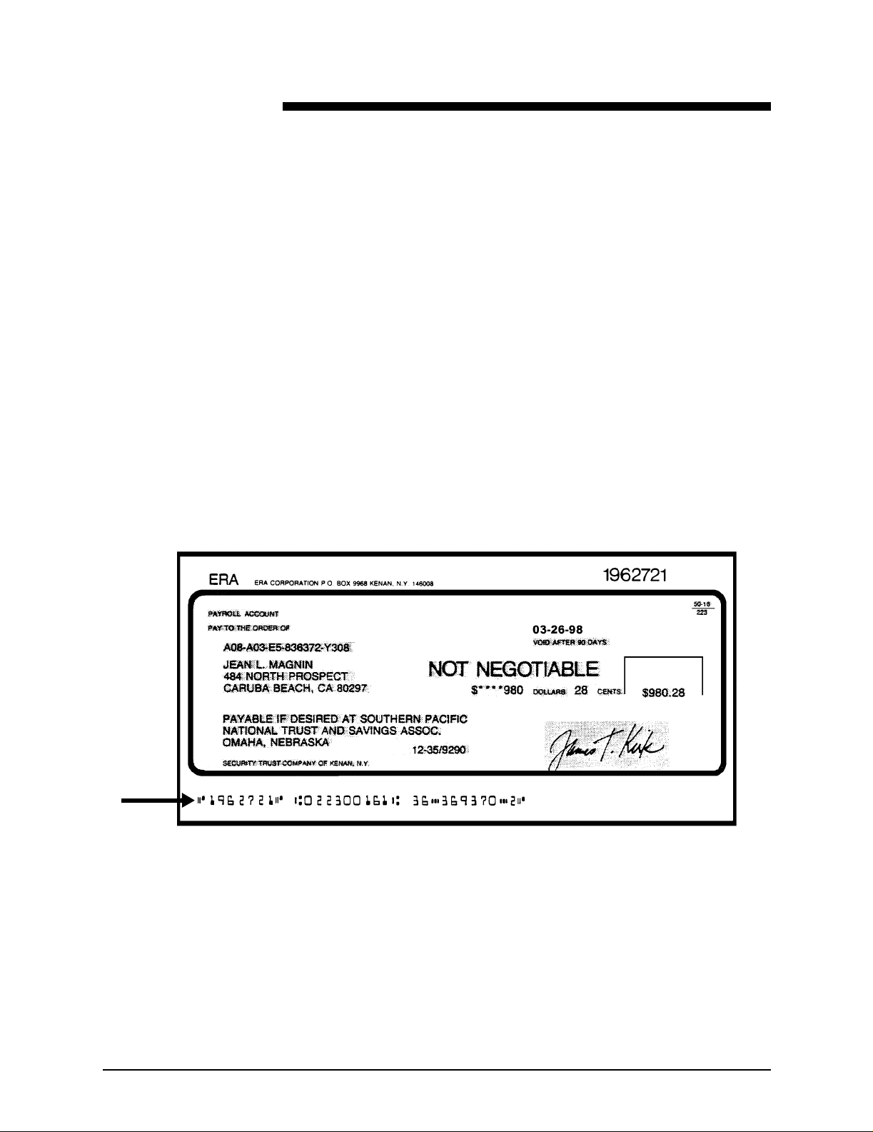
The following figure shows a check with a MICR line. This line
contains block-shaped numbers running along the bottom of the
check, and non-numeric characters called “symbols.” This entire
string of numbers and symbols is printed using magnetic ink.
Figure 1-1. MICR line on a check
Generic MICR Fundamentals Guide 1-1
Page 12

Overview
A brief history
Originally, checks were processed manually. However, by the
mid-1940s the banking system became inu ndate d wit h pape r as
society grew more mobile and affluent. Finding a means of
handling the growing number of paper documents became vital
to bankers. The banking and electronics industries searched for
a standard process that could be used in all banks throughout
the country.
In the mid-1950s, the first automated processing of checks was
initiated. The system that is now kno wn as MICR was developed
by the Stanford Research Institute, using equipment designed by
the General Electric Computer Laboratory. The E13B MICR font
was also developed.
The specifications for producing the E13B font using magnetic
ink were accepted as a standard by the American Bankers
Association (ABA) in 1958. In April 1959, the ABA issued
Publicat ion 147, The Common Machine Language for
Mechanized Check Handling.
Deluxe Check Printers had the task of translating the
specifications in to a wo rking pr oce ss. By the end of 1959,
Deluxe successfully produced checks using magnetic ink.
In countries throughout the world there are groups that s et
standards and di ctate the design specifications for document
encoding, processing equipment, and quality criteria for MICR
printing. Some of these are:
• American Banking Association (ABA)
• American National Standards Institute (ANSI)
• United Kingdom—Association for Payment Clearing Services
(APACS)
• Canadian Payments Associa ti on (CPA)
• Australian Bankers Association (ABA)
• International Organization for Standardization (ISO)
• France—L'Association Francaise de Normalisation
1-2 Generic MICR Fundamentals Guide
Page 13

Overview
In 1963, the American National Standards Institute (ANSI)
accepted the ABA specifications, with minor revisions, as the
American standard for MICR printing. The ANSI publication
covering th ese st an dar d s is Print Specifications for Magnetic Ink
Character Recognition, first issued in 1969. Although compliance
with the standards is voluntary in the U. S., the banking industry
considers them to be the definitive basis for determining
acceptable quality of a MICR document.
Another MICR font, called CMC7, was developed by the French
computer company Machines Bull and has been the official
French standard since September 1964. The CMC7 font is also
used in other co untries, includ ing Italy, Spain, and Brazil. Like the
E13B font, CMC7 is a magnetically readable font, but with a
different character design and recognition criteria.
Some countries also use OCR-A or OCR-B, which are optically
read check processing fonts. These fonts do not need to be
printed with magnetic ink in order to be processed. The following
table show s which countrie s use the four check printing fonts.
Generic MICR Fundamentals Guide 1-3
Page 14
Overview
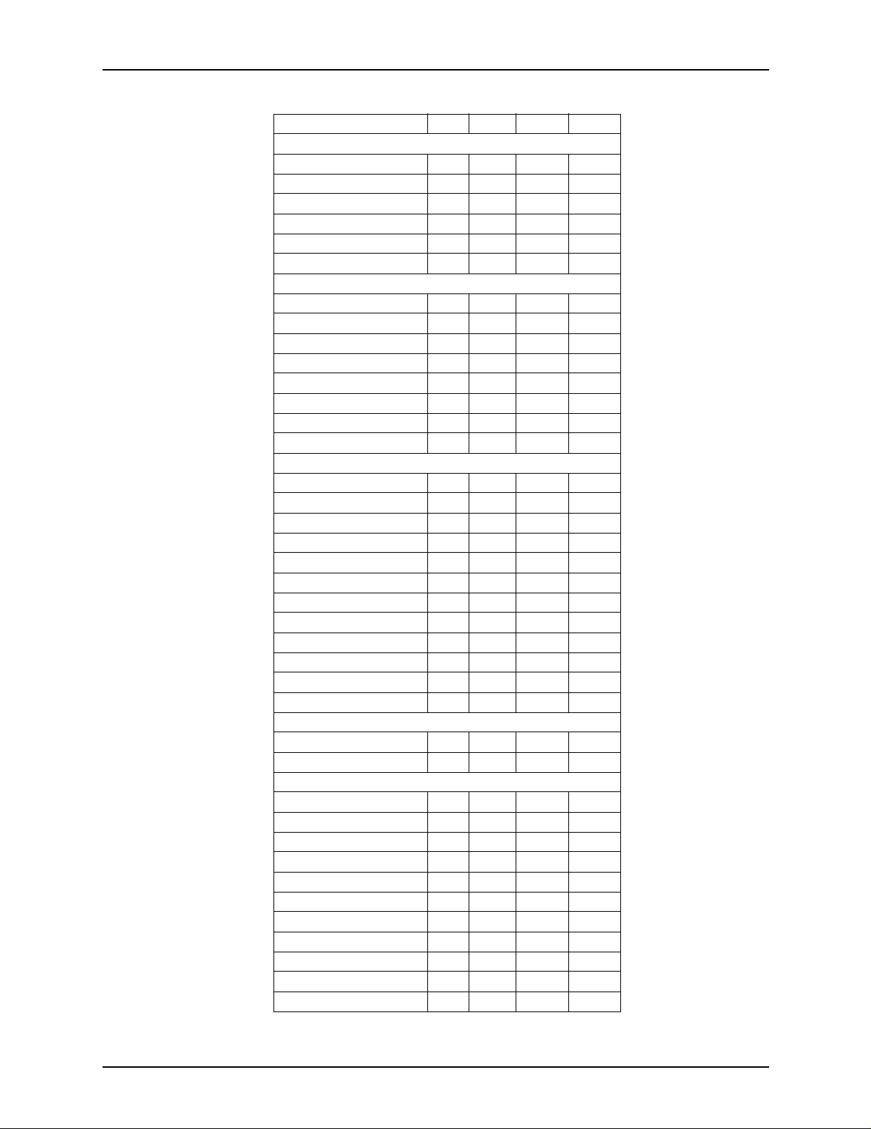
Country E13B CMC7 OCR-A OCR-B
North America:
USA X
Canada X
Central America
Bermuda X
Mexico X
Panama X
South America:
Argentina X
Brazil X
Chile X
Columbia X
Ecuador X
Peru X
Uruguay X
Venezuela X
Europe:
Austria X
Belgium X X
Denmark X X
Finland X X
France X
Germany X
Holland X X
Italy X X
Norway X X
Spain X
Sweden X X
United Kingdom X X
Middle East and Africa:
Israel X
South Africa X
Far East:
Australia X
Hong Kong X
India X
Japan X X
Kuala Lumur X
Malaysia X
New Zealand X
Philippines X
Singapore X
Taiwan X
Thailand X
1-4 Generic MICR Fundamentals Guide
Page 15

Why MICR?
Overview
Recognizing significant market value in combining the
advantage s of electronic la ser xerog raph y with MICR t echnolog y,
Xerox initiated investigations in late 1979 and early 1980. Early
efforts at the Xerox Webster Research Center concentrated on
basic material physics. The objective was to provide a
xerog raphic dry ink and de v eloper that wou ld produce high visual
quality images that could be read using the standard banking
reader sorter equipment.
Xerox’s MICR printing products combine the following:
• A modified xerograph ic engine
• A unique magnetic materials package
• The standard ANSI and ISO MICR character sets
The Xerox MICR systems meet ANSI, CPA, and ISO
specifications for automatic check handling.
MICR was chosen by th e ABA beca use it can be read accur ately
by machine, it uses existing printing technology, and the printed
documents are durable to withstand mutilation.
A MICR encoded document can be read through overstamping,
pen and pencil marks, oils and greases, and carbon smudges.
However, MICR printing is one of the most quality-conscious
application areas within the printing industry. It meets ABA
security requirements for negotiable documents. MICR is the
only system that produces reliable results at high processing
speed.
Check printing capabilities
A Xerox MICR printing system with a magnetic material package
and MICR fonts can print a character line at the bottom of a
check form that is machine read able by standard banking re ader
sorter equipment. On blank security paper, the Xerox MICR
printing system can produce the entire check image, including
the form, all fixed and variable data, logos and signatures, and
the MICR line, in a single pass.
Generic MICR Fundamentals Guide 1-5
Page 16

Overview
The printing process is one small part of the total processing
procedure for a MICR printing system user . Quality and accura cy
of the check documents must be closely controlled during
printing to prevent problems from occurrin g when the documen t
is processed off-site.
Check processing procedure
All checks impact at least three parties:
• The person who writes the check
• The person to wh om the check is being pai d
• The bank at which the check writer has an account
Depending on where and by whom the check is deposited, how
the check is processed, and how the check is handled for funds
clearance, many different parties can handle the same check.
Fraud can occur at any of the steps or access points in this
process.
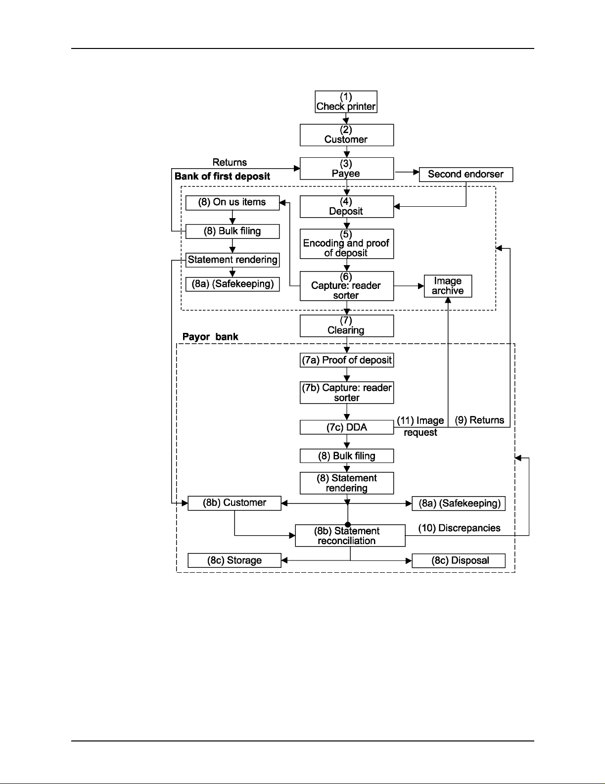
The following steps, illustrated in figure 1-2, trace a document
through a series of corporate and banking system procedures
typical of the MICR environment.
1-6 Generic MICR Fundamentals Guide
Page 17
Overview
Figure 1-2. Life cycle of a check
Generic MICR Fundamentals Guide 1-7
Page 18

Overview
1. The check printer (1) produces a blank check that will be
completed later. This check includes the static data that is
needed for a negotiable document:
• Financial institution name and address, issuer name and
address, che ck form, company logo, etc.
• The MICR line, containing the account and routing
information that is needed to process the check
• Other audit, account, and report information as required
by the customer
2. The customer (2) adds the transaction information—payee,
amount, and date—and authorizes the funds transfer with a
signature.
NOTE: When using a MICR laser printer, steps 1 and 2 may
happen simultaneously.
3. The completed check is transferred to the payee (3), who
deposits it in the bank of fir st deposit (BOFD). The pa y ee may
receive the check in person, by mail, or through a third party.
A third party check may require a second endorsement.
4. Deposits (4) are mad e in se v er al ways: through a teller, u sing
an automated teller machine (ATM), us ing a drop box, or
through a postal lock box. Deposited items are accompanied
by a deposit ticket that lists and totals the items and identifies
the payee account.
This is the entry point for the automated payment processing
system.
5. The BOFD encodes the amou nt of the chec k in the MICR line
(5) and balances the check against the deposit ticket to verify
that the correct amount is being credited to the payee
account (proof of deposit) .
6. MICR documents that are printed on a Xerox MICR printing
system are usually corporate paychecks, stock dividend
checks, etc. After printing, these type of documents require
additional processing using a high-speed device called a
“reader sorter .” The r e ade r sorter identifie s ea ch m ag ne ti z e d
character and symbol of the MICR line using logical analysis
algorithms of the electronic wave patterns that the characters
produce.
In the “capture pass,” checks are read in a reader sorter for
the first time (6). At this time, they are sorted into checks
drawn on the BOFD, known as “On-us items” (8), an d chec ks
drawn on other banks.
1-8 Generic MICR Fundamentals Guide
Page 19

Overview
7. Checks drawn on other banks are sent to the payor bank
through a clearing (7) arrangement. The check may be
cleared through the Federal Reserve, a correspondent bank,
a clearing house, or directly by the issuing bank.
The payor bank also balances the check against the deposit
ticket (proof of deposit) (7a) to verify the check amount, and
performs its capture pass (7b) on the reader sorter in order to
identify the issuer account (7c). (Refer to the “Proofing
checks” section of chapter 5 f or more information on this part
of the process.)
8. In most cases, the check is debited from the issuer account
and moved to bulk filing (8), where it is stored until time for
monthly statement rendering.
Fro m this point f orward, an On-Us item is treated the same as
one that was cleared to anothe r bank.
Two exceptions may occur:
• If the payor bank does not honor the check, it is returned
(9) through the BOFD to the payee. The amount is then
deducted fr om the payee account.
• During reconciliation, the account holder may discover a
discrepancy (10) between its records and those of the
bank. Their bank then researches any discrepancies.
NOTE: Account holders may contract with their banks to
perform reconc ili at i on before clearing the check.
Production cycle of a check
The check production process starts as soon as the need is
identified. Design requirements shou l d co mp re he nd purchasing,
distribution, warehousing, manufacturing, internal and external
processing requirements, and the needs of the check issuer.
Banks frequently require new corporate accounts to submit
checks for approval before the banks approve the account.
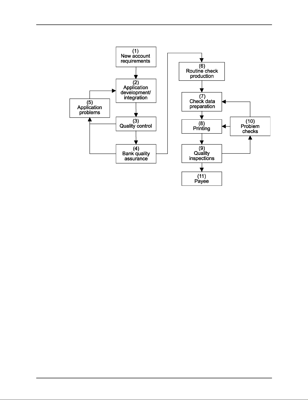
The following steps, illustrated in figure 1-4, describe the typical
process that is required before the first negotiable checks are
delivered to the payee.
Generic MICR Fundamentals Guide 1-9
Page 20
Overview
Figure 1-3. Check ordering and production cycle
1. Design requirements are defined for a new account.
2. Requirements are passed to application development.
3. Samples pass internal quality checks.
4. Samples are forwarded to the bank for approval.
5. Any problems are referred to application developers, who
ensure that th e problems cannot occur in production.
6. After approval by the bank, the check design becomes
available for routine production.
7. Variable check data is prepared for incorporation.
8. The checks are printed.
9. The printed checks are inspected.
10.Any problems are repo rted to the source f o r cor r ection and
reprinting.
11.When they have pa ssed ban k validation and quality
inspection by the issuer, the checks are issued to the payee.
1-10 Generic MICR Funda m entals Guide
Page 21
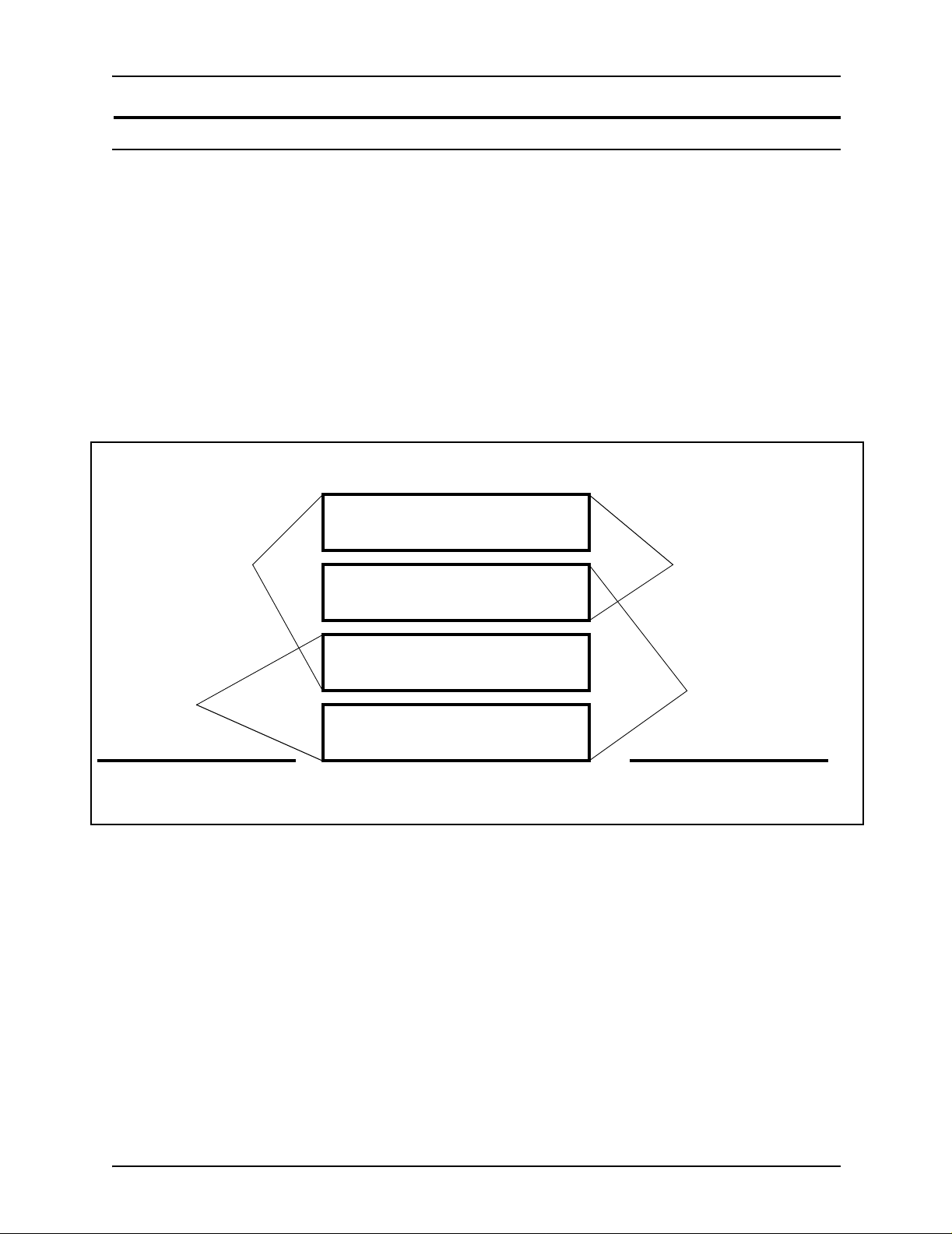
Changes in check creation role
In the past, the roles of manufacturer and check issuer were
distinct. Because the technical requirements of doing MICR
printing were f airly diffi cult, the man uf acturer usuall y did all of the
process steps that involved the generation of the check, except
for entering the amount, date, and payee.
The introduction of MICR impact printers allowed the check
issuer to sometimes take over printing the MICR line. With
further technological adv ances , such as t he Xero x MIC R printing
systems, the check issuer has assumed still more
responsibilities that previously belonged to the manufacturer.
- - - - - Printing functions - - - - -
Overview
Manufacturer
Check
issuer
Old areas of
responsibility
Background
Manufacturer
Form and border
MICR line and serial number
Check
issuer
Amount and payee
New areas of
responsibility
Figure 1-4. Changes in check creation roles
Because MICR documents are typically negotiable documents,
every possible measure must be taken to ensure successful
processing. With a less clear division between check
manufacturer and check issuer responsibilities, the check issuer
becomes more involved in the development of a new check
issuance application.
Generic MICR Fundamentals Guide 1-11
Page 22

Overview
1-12 Generic MICR Funda m entals Guide
Page 23

2. Environment
Checks and other bank forms constitute the most frequent uses
of MICR printing. All businesses issue checks to meet payroll
and accounts payable obligations. In addition, all profitable
publicly owned businesses make periodic stock dividend
distributions by chec k.
Most medium and small companies buy check production
services from a service bureau or a bank. Individuals who once
obtained personal checks through their banks can now buy
checks through the mail from check printers.
A major trend in the banking industry is check truncation.
Truncation refers to the ability of the bank of first deposit to
process MICR documents, both theirs a nd those belonging to
other banks, without further transfers of the paper document
(check). The check is processed electronically. This reduces
cost and improves check clearance.
Types of MICR applications
A MICR system need not be dedicated to chec k printing or to any
other MICR-specific application. A MICR system operates no
differently from an identical system that does not have MICR.
MICR and non-MICR systems ma y be mixed at a site and do not
impact scheduling of jobs that do not require MICR magnetic
materials.
MICR printing is most frequently used for the following types of
applications.
Manufacturing checks
Check manufacturing refers to the process of converting milled
paper into finished check and deposit books, computer
stationery, etc. This is usually done by a small group of specialty
or security printers, mail order check printers, and others. MICR
printing systems are becoming more popular in this market.
Generic MICR Fundamentals Guide 2-1
Page 24

Environment
Issuing checks
Issuing turnaround documents
The most common use of MICR printing systems is the process
of obtaining check stationery from the manufacturer and
encoding it with MICR information. Most businesses regularly
issue checks in at least two of the following categories.
• Payroll checks
• Accounts payable checks
• Dividend checks
• Benefit checks
•Drafts
•Warrants
• Negotiab l e or de rs of wit h drawal
Turnaround documents refer to any type of volume transaction,
whether negotia ble or not, that requires data capture. Familiar
examples of turnaround docum en ts are :
• Credit card invoices
• Insurance payment booklets
• Instant re bate coupons
Turnaround document s are also used in remittance processing,
which is a procedure for handling items returned with a payment.
MICR encoded tu rnaround documents enable organizations to
cut their resource and equipment costs. For example:
1. A bank card compan y MICR enco de s an accou nt number on
the bill and remittance slip that is sent to the customer.
2. The payment is returned with the remittance slip. When the
bank card company receives the check and payment slip, the
two documents are visually checked to see that the amounts
are the same on both.
3. The documents are processed by a MICR reader sorter,
which reads magnetic ink characters.
2-2 Generic MICR Fundamentals Guide
Page 25

Printing financial forms
MICR is also used for printing a variety of financial forms.
Examples of MICR financial forms include:
• Personal checkbooks
• Limited transaction checks, such as money market checks
• Direct mail promotional coupons
• Credit remittance instruments
• Internal bank control documents, such as batch tickets
Xerox MICR printing systems
The Xerox MICR printing systems are a unique range of
products that combine speed, intelligence, and high print quality.
They also provide great flexibility in font selectivity, graphics
capability, and dynamic page f ormatting .
Environment
An advantage to Xerox printing systems is their ability to print a
document in a si ngle pass, as shown in the following figure. The
form design, variable data, logos, and signatures can all be
printed together. With MICR enablement, the MICR line can be
included.
Additional benefits incl ud e:
• The elimination of expensive production and inventory of preprinted forms
• The ability to produce multiple checks on one physical page
• Reduced handling steps by using cut sheet rather than
fanfold paper
• The reduction of additional equipment, such as burste rs,
decollators, trimmers, and signature machines
• Reduced turnaround time
• Ability to print checks against multiple accounts
With the introduction of the latest MICR printing systems, Xerox
has expanded its application base, using more paper sizes and
multiple paper stocks.
Generic MICR Fundamentals Guide 2-3
Page 26

Environment
MICR printing technologies
The following basic printing techniques are capable of
generating magnet ic characters:
• Letterpress
Letterpress is based upon a raised typeface that sits above
the plane of the image carrier. The typeface is inked with
special magnetic ink and applied to the paper under
pressure. Common forms of letterpress are: hot metal type,
sequential number machines, and ribbon encoders.
• Offset lithography
Large offset devices are typically used to produce check
stationery. The lithographic process uses magnetic ink and
water to shap e the image on a plate . The i mage is tran sf erred
to a rubber sheet called a blanket. The image is then “offset”
to the paper.
• Impact ribbon encoding
Ribbon encodin g, al so ca l led “ d ir e c t prin ti ng ,” i s a le tterpress
technology with a different delivery method. Instead of the ink
being applied to the typeface and then to the paper, the ink is
suspended on a thin sheet of backing (usually a polymer
base) called a ribbon.
The ribbon is held between the typeface medium (drum,
daisy wheel, or hammer) and the pap er, so that when the
typeface is struck against the paper, the components on the
ribbon are trapped and pressed onto the document to be
printed.
• Non-impact (xerography and ionography)
Non-impact printing technologies have been growing in
market penetration. They require highly sophisticated and
consistent equipment utilizing magnetic materials.
• Thermal ribbon encoding
A non-impact, thermal transfer version of ribbon encoding
combines some of the charac terist ics of the conventi o nal
ribbon encoding with those of non-impact technology.
2-4 Generic MICR Fundamentals Guide
Page 27

Printer technical optimization
The Xerox MICR systems use the same operating software as
their standard configuration counterparts. In addition, the MICR
systems have been enhanced to include the following features:
• Optimized print engine
• MICR materia l s package
• Optimized paper handling system
• Digitized MICR font
Optimization of the MICR print engines subsystem is required b y
the physical properties of the dry ink. As a result of these
changes, dry ink and de v eloper a re not intercha ngeable between
MICR and non-MICR printers, unless specifically designed to
accept more than one type of materials.
The Xerox MICR systems have a paper handling system
designed for the highly accurate registration. This is required for
precise placement of the MICR line t o maximize readability
during check processing.
Environment
Typical MICR printing concerns
The following areas of MICR user concerns have made banks
want to increas e reli ab ili ty of the MIC R docum en t gene r a ti ng
process:
• Security: This can be addressed by providin g high security
within the document creation process. In addit ion,
counterf ei t in g can be reduced by the use of v a rious des ig n
and production technique s.
• Quality: Sensitive to the banking industry demands, printing
businesses maintain tight quality control procedures.
• Production speed
• Cost
In addition to their need to adhere to required print quality
standards, they have the following concerns about the pr inting
operation:
• Traditional MICR printing devices are labor intensive.
Generic MICR Fundamentals Guide 2-5
Page 28

Environment
• High security measures are needed in any environment that
uses check stationery. These measures affect physical
access restrictions and staff supervision.
• Check printing usually requires frequent starting and
stopping, which is time-consuming and degrades print speed.
• Storing hundreds of different preprinted check and deposit
forms can be costly.
• Short print runs of continuous forms can waste materials.
• Check production requires short lead times.
Xerox MICR printing systems reduce many of these concerns.
There is no need to store dif f erent type s of preprinted f o rms, and
single pass printing eliminates many time constraint s.
2-6 Generic MICR Fundamentals Guide
Page 29

Paper guidelines
3. Paper facts
MICR applicatio ns have special pa per, print, and finishing
requirements . Ref e r to y our printer ope rato r guid e f or a co mplete
list of supplies and options.
Refer to Helpful Facts about Paper for information on solving
printer problems relating to paper.
The paper that you use to print MICR documents must meet the
criteria for the Xerox MICR laser printer and the specifications
imposed by MICR industry standards. In addition, papers must
resist alteration and prevent duplication of negotiable
documents. They must support hi gh print quality and feed
through the printers properly.
NOTE: Some b ankin g a uth oritie s spe cify the type and weight o f
paper that should be used for check printing in that country. It is
essential that only the specified paper be used.
Follow these guidelines for best results:
• Understand check stock security requirements, and use
security features that do not degrade printer performance.
• Do not accept delivery of paper or forms that are not reamwrapped in a moisture barrier.
• Do not open paper reams until you are ready to load the
paper into the printer.
• Store paper in the printer room for at least 24 hours before
using it. This allows the paper to stabilize to the temperature
and relative humidity of the room.
• Do not allow the printer room t o become e xcessive ly humid or
dry. This can cause a differ en ce i n moi stu re content between
the edges and center of each s heet of paper, and result in
feeding, image permanence, or image deletion problems.
Generic MICR Fundamentals Guide 3-1
Page 30
Paper facts
• Do not use cut-sheet check paper that was converted from
fanfold by the paper distributor. This conversion process can
result in dimensional inaccuracy, poorly cut edges, and
unacceptable paper curl.
MICR paper requirements
The following table summarizes Xerox’s recommendations for
papers that are use d f or MI CR printing. P ap ers with the f ollo win g
characteristics perform best in Xerox MICR printers.
Table 3-1. Xerox paper recommendations
Paper characteristics Recommended for optimal printer and reader/sorter performance
Basis weight 24-pound/90 gsm
Sheffield smoothness 80 to 150
Grain direction Parallel to the long edge of check or MICR document. Short grain direction
may be acceptable for personal, 6 inch/152 mm checks.
Moisture content 3.9 to 5.e per cent
Reflectance 60 percent minimum
Curl Refer to instructions in your MICR printing system operator guide
Perforations 60 to 80 ties per inch
Metallic content No ferromagnetic materials can be present in the paper.
Stiffness For recommendations, refer to “Paper stiffness,” later in this chapter.
Cutting precision +/- 0.030 inch/0.762 mm length
+/- 0.030 inch/0.762 mm width
Coating Do not use paper containing clay or resin coatings.
Lamination Do not use stock that is a combination of paper and plastic.
Preprinting ink Must be heat resistant to approximately 400 degrees F/204 degrees C for laser
printing. Heat resistance varies according to manufacturer.
Size Refer to instructions in your MICR printing system operator guide
Basis weight
Basis weight is an industry term for expressing the weight per
unit area of paper . P aper weig ht is generally e xpressed as g rams
per square meter (gsm), a measure that makes it easy to
compare any two pieces of paper, even if the papers are of
different types, such as offset and index.
3-2 Generic MICR Fundamentals Guide
Page 31

Paper facts
In the United St ates, paper weights ar e given as the weight of
500 sheets of paper of a particular size. The size of the basis
sheet, however , v aries with the type of paper. This makes difficult
any comparison of weight between different types of paper. For
example, 50 pound xerographic bond is not the same as a 50
pound offset pa per, and both are different from a 50 pound in dex
stock.
Xerox MICR printing systems produce the best quality and
highest throughput using the Xerox recommended 24 pound
(U.S. market) or 90 gsm xero g raphic paper. Lighter papers often
cause misfeeds, and heavier papers are more subject to jams
(although most Xerox printing system s can handle a wide range
of paper weights).
In multi-pass reader sorter processing, lighter weight papers
subject to frequent misfeeds and mechanical stresses, and are
not as reliable as 24 pound paper.
Sheffield smoothness scale
The smoothness of your paper can impact image quality. With
increasing roughness, the print quality of solids and halftones
degrades. Extremely rough paper does not properly accept
fused dry ink, which rubs or flakes off.
Rough papers require a higher density setting and more ink than
smooth papers to achieve the desired level of image darkness,
because surface irregularities must be filled in with ink.
Papers must measure 50 to 200 when they are measured by a
Sheffield smoothness instrument, in order to meet ANSI
standards. Higher numbers indicate roug her paper.
Xerox has conducted extensive image quality testing on
xerog r aphi c , bo nd, an d offset paper s . The smoot her xerographic
and bond grade papers provide the best image quality. Xerox
recommends a Sheffield smoothness of 80 to 150.
If you use preprinted forms, check with your forms supplier for
the smoothness quality of the form before you make a bulk
purchase.
Generic MICR Fundamentals Guide 3-3
Page 32

Paper facts
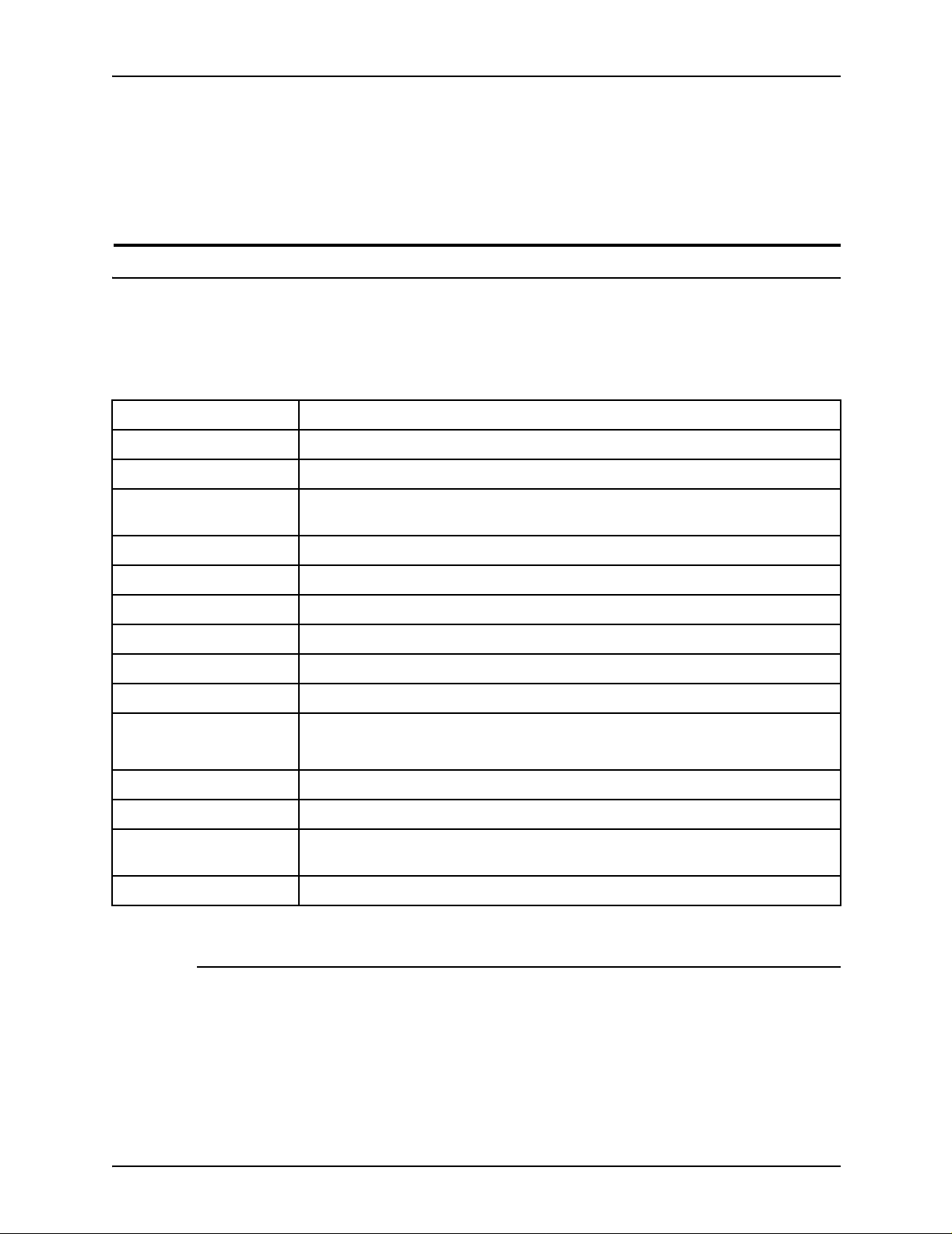
Grain direction
Pape r prop erties are related to the g ra in di rect ion. The g r ain of a
paper is the direction in which most of its fibers lie, as shown in
the following figure. Long grain papers are cut so that the fibers
are aligned with the long dimension of the cut sheet. Short grain
papers have the fibers aligned with the short dimension of the
sheet.
You can use 24 pound paper in either grain direction. If your
paper is light er than 24 pound, use it only for document s in which
the grain is in the long dimension of the finished document. For
long grain MICR-processed documents, the minimum paper
weight is 20 pounds.
NOTE: 24 pound, long grain paper is recommended for MICR
printing.
Long grain sheet cut from
paper web
Paper web - made during
paper making process
The following figure shows the relationship between long and
short grain documents and the MICR processing direction. The
shaded areas represent typical documents that would be cut
from these s heets for MICR processing.
Pulp fibers
Short grain sheet cut from
paper web
Paper making
process direction
Figure 3-1. Long and short grain
3-4 Generic MICR Fundamentals Guide
Page 33

Paper facts
11" 11"
Moisture content
Too much moisture in paper causes excessive curl, jams,
degraded image permanence, and print quality problems. Too
little moisture causes static problems, which can lead to jams,
misfeeds, and difficulties in post-processing paper handling.
Papers with a nominal moisture content of 4.7 per cent perform
best in Xerox MICR laser printers. Offset and bond papers may
have a higher moisture con tent than xerographic pape rs.
Xerox brand papers have a maximum moisture content of 5.3
percent, with an average of 4.7 per cent. Several other MICR
bond papers have moisture content of less than 5.3 percent.
Preprinted papers must have a moisture content within these
limits after preprinting.
8.5"
8.5"
Figure 3-2. Long and short grain documents
Reflectance
All MICR materials must meet a background reflectance
standard of 60 per cent minimum, as measured by equipment
having a CIE Photopic Spectral Response. Backgrounds
containing patterns, designs, logos, or scenes must meet
additional limits on the contrast of the preprinted areas. These
background reflectance standards were developed to permit
machines to read information on the check, such as the
convenience amount field.
Generic MICR Fundamentals Guide 3-5
Page 34

Paper facts
Requirements for background reflectance are discussed in
chapter 4, “Document design.”
Curl
All papers curl to some degree. Excessiv e curl is one of the most
common causes of paper jams. Selecting a low-curl paper with
the proper moisture conte nt mak es a signi fica nt difference in the
productivity of your system. Refer to the operator guide for your
printer for paper curl recommendations specific to your printer.
Because the front and bac k surf aces of th e paper, as determined
during the paper making process, differ slightly in their makeup,
one side is preferred as the side to image firs t. If you are using a
quality 24 pound/90 gsm paper intended for xerographic
purposes, the ream wrapper is marked with an arrow that
indicates the preferred printing side. Print on this side for onesided printing. For two-sided printing, print on this side first
(unless instructed otherwise in the operator guide for your laser
printer).
Perforation
How you load preprinted paper is determined by the preprinting.
Preprinted forms should be produced so that their curl is
compatible with the requirements in your MICR printer operator
guide.
When you use perforated paper, your objective is to have a
smooth, free-feeding sheet that retains sufficient beam strength
to prevent sheet fold-over, buckling, or jams.
If you use preperforated forms, consider the following fa ctors:
• Use 24 pound/90 gsm paper.
• Use a perforation that lets the sheets retain as much stiffness
as possible. Reduced stiffness may result in jamming and
paper mutilation.
• Perforations should be nine per inch.
• All holes should be the same size.
• The ratio of holes to paper (tie size) should be less than or
equal to 1:1. In oth er w or d s, the tie size sh oul d be at l e ast a s
large as the hole size.
3-6 Generic MICR Fundamentals Guide
Page 35

Paper facts
• If you are using micro-perf orati ons, be sur e to hav e more than
60 ties to the inch.
• Make sure that the perforation line is rolled sufficiently to
eliminate the underside bulge (debossment). Otherwise,
feeding and stacking may be unreliable and print deletions
may occur.
• When paper is perforated, a ridge or dimple forms around the
holes. Make sure that the design and placement of the
perforation does not cause document edge irre gularities.
• Do not use puncture-type perforations that are not ironed
smooth. They prevent the stack from lying flat, which can
cause feeding problems and deletions. Use rolled
perforations instead.
• Make sure that the perforation design and placement do not
cause document edge irregularities.
• Make sure that die-cut perforated papers are free of paper
dust and chaff.
• Avoid printing any text or forms data within 1/8 inch/3.2 mm of
• For printers that use edge registration: Full-length perforation
Metallic content
Paper stock materials for MICR applications cannot contain
ferromagnetic particles.
Stiffness
Stiffness ref er s to th e rigidity or be ndi n g re si stan ce of the pa pe r.
Thicker papers are usually stiffer. In general, 16 pound/60 gsm
and lighter papers are not as stiff as heavier stocks. They may
bunch up or wrinkle in the printer, causing jams and misfeeds.
Heavier papers, such as cover and index stock, may jam more
frequently and have more print quality defects (skips, blurs, and
deletions) due to their reduced ability to bend.
any perforation.
that is parallel to the registration edge should not be closer
than 1.5 inches/37.5 mm to that edge.
24 pound/90 gsm paper usually provides stiffness levels in the
range needed by the Xerox MI CR la ser printer and the proofing,
reader sorter, and remittance-processing systems used in
banking environments.
Generic MICR Fundamentals Guide 3-7
Page 36

Paper facts
Stiffness is lower across the grain direction than in the grain
direction. Documents having the grain r unning parallel to the
short dimension of the pa per require special consideration to
ensure adequate stiffness. Sh ort grain MI CR documents are
restricted to papers with a basis weight of 24 pound/90 gsm or
higher.
Cutting precision
Pape r for MICR printing applicatio ns sho uld be fr ee o f al l de f ect s
that could interfere with reliable feeding, such as edge-padding
and folded or bent she ets.
NOTE: Fan all paper before loading it.
The squareness of each sheet must be precisely controlled to
ensure optimum MICR ba nd re gi stration. The dimensions must
be controlled to ±.030 inch/0.762 mm.
Xero x paper
Papers that have been converted from continuous for m paper
present a risk of jams and poorly registered forms in a Xerox
MICR laser printer.
To ensure reliability, X erox has developed paper w i th the
optimum characteristics for xerographic printing. Every lot of
Xerox paper is tested at least three times:
1. At the mill by the manufacturer
2. In Xerox quality-assurance laboratories
3. In Xerox laser printing systems prior to shipment
Xerox 4024 Dual Purpose 24 pound paper is recommended for
MICR printing in the U. S. and Canada. This paper has been
extensively run on Xerox MICR laser printing systems. It closely
complies with all MICR paper specifications and is suitable for
printing MICR encoded documents that will be proces sed
through high-speed reader sorters.
3-8 Generic MICR Fundamentals Guide
Page 37

Paper maintenance
Wrapping factors
Paper facts
The physical condition of your MICR paper is extremely
important. In addition to being free from holes, wrinkles, tears,
damaged edges, and foreign material, MICR paper must be
carefully maintained, both before and after printing.
Paper with a moisture content below 5.5 per cent is best for a
Xerox MICR laser printer. The moisture content must be uniform
within the ream, which should not be allowed to lose or gain
moisture duri ng storage.
To best preserve paper and pr eprinted f orms, use moistu re-proof
ream wrappers, which maintain critical moisture balance.
Xerox paper is covered with a polyethylene laminate ream
wrapper. This material is the most effective in resisting the
transfer of moisture from the environment. Unlike wax laminate
wrappers, polyethylene does not bleed through the paper covers
when exposed to heat. Wax bleed-through can cause f e ed i ng
problems. Discard the top and bottom sheets if you suspect wax
contamination.
Storage factors
Xerox paper are packaged in protective heavyweight cartons,
which you can reuse for storage. These cart ons are transported
on a wooden pallet that provides uniform support and protection
to the bottom layer of cartons. The cartons are protected with a
moisture barrier of plastic shrink-wrapping.
Generic MICR Fundamentals Guide 3-9
Page 38

Paper facts
Temperature and humidity conditions
The temperature and humidity in the printer environment can
affect runability and print quality. Use the following guidelines for
the best MICR printing performance:
• Optimum temperature and humidity range
– 68 to 76 degrees F / 2 0 to 14 degrees C
– 35 to 55 percent humidity.
Store all paper on a wooden pallet. Placing paper directly on
the floor increases moisture absorption.
• If you move paper from a storage area to a location with a
differen t t empe ratur e an d hum idit y, condition the paper to the
new environment before using it. The time you should wait
between paper storage and use is listed in the following table.
Table 3-2. Temperature conditioning chart
Temperature
difference 10° F 15° F 20° F 25° F 30° F 40° F 50° F
Number of boxes Hours Hours Hours Hours Hours Hours Hours
1 4 8 11 14 17 24 34
5 5 9 12 15 18 25 35
10 8 141822273851
20 11 16 23 28 35 38 67
40 14 19 26 32 38 54 75
For example, if you want to move 10 cartons (boxes) from
your storage area at 55 degr ees F to you r printing room at 75
degrees F, (a change of 20 degrees), you should let the
cartons stand unopen ed in your printing room for at least 18
hours before use.
• Store paper inside the original carton and ream wrappers
until shortly before use.
• Reduce excessive curl by storing the paper in a dry
environment for several days.
3-10 Generic MICR Funda m entals Guide
Page 39

Paper runability criteria
Use the f ol l owing criteria to a void paper jams and to assure high
image quality:
• Use 24 pound/90 gsm xerographic or dual purpose MICR
bond paper. The paper should have the following
characteristics:
– Low moistur e cont en t (be lo w 5.3 per cent)
– Built-in curl control
– Smooth surface (smooth er than most offset or bond
– No mechanical defects
– Moisture-proof wrapping
• Correct temperature and humidity are also important. Refer
to the “Temperature and humidity conditions,” earlier in this
chapter.
Paper facts
papers)
Your service representative can verify that the MICR printing
system is adjusted within design tolerances. If a paper runability
problem persists, consider changing:
• The ream, carton, or request paper from a different lot
• Your type, weight, or brand of paper
• The conditi ons under which the paper is stored
• The temperature or humidity of the printer environment
• The time elapsed between unwrapping and printing
Generic MICR Fundamentals Guide 3-11
Page 40

Paper facts
Malfunction Possible causes
Repeated processor jams • Excessive curl
Paper multi-feeds or skew feeds • Poorly cut paper
The follo wing tab l e is a troub leshoo ting gui de f or pape r runability
issues.
Table 3-3. Paper runability issues
• High moisture content in paper
• Excessive paper smoothness
• Bent corners
• Predrilled paper plugs
• Excessive moistu re in printer or paper
storage environment
• Paper not acclimated to printer environment
• Wrapper wax or glue on sheets
• Low humidity in printer environment
• Poorly drilled paper
• Paper too porous
Paper misfeeds • Poorly cut paper
• Excessive curl
Jams in stacker bin • Excessive curl
• High moisture content in paper
• Excessive moistu re in printer or paper
storage environment
Sheets stick together in stacker • Low humidity
• Paper dust on static eliminator
Poor copy quality • Rough paper
• Incorrect paper conductivity
Leading edge of the paper tears • Poorly cut paper
• Paper too lightweight
• Excessive curl
Spots on copy • Wrapper wax or glue on sheets
• Excessive paper dust
• Dust from poor perforations
• Wax or soap used on drill
3-12 Generic MICR Funda m entals Guide
Page 41

Preprinted forms considerations
The combination of consistent data format and element location
makes preprinted forms useful in M ICR applications. Additional
requirements for security features, either in the base paper stock
or in the preprinted for m, come from the need to protect a
financially negotiable documen t .
You need to consider several factors related to ink and paper
when selecting a preprinted form for any type of laser printer.
Preprinted check stock must not offset (transfer from a printed
sheet onto other surfaces). Work closely with the forms vendor to
ensure that requirements are und erstood and met. Always test
the application on the appropriate printer before production
printing.
Inks
Paper facts
Choosing the correct ink is the first step in designing forms that
function well in Xerox printers. Inks for these forms must cure
well, must not be tacky, and must not offset. In choosing an ink,
you must consi der the am oun t of heat a nd pressur e to whic h the
forms will be ex po sed whil e passin g thr ou gh the printer. You
must also consider the dwell time–the amount of time that the
preprinted paper is subjected to those conditions.
Good performance has been reported with the following ink
types:
• Oxidative inks: The following qualities are desirable in
oxidative inks:
– Non-volatile, cross-linkable vehicles
– Internal and surface-curing driers
– Minimal use of anti oxidants
– No slip agents
– pH in the press fountain high enough to permit curing
NOTE: Oxidative inks can require several days to harden
satisfactorily.
• UV cured inks: Inks that are cured using UV (ultr avi olet) li ght
change immediately from liquid to solid upon exposure to an
intense UV light source.
Generic MICR Fundamentals Guide 3-13
Page 42

Paper facts
• Laser inks: Inks that are formulated specifically for use on
forms that will pass through laser pri nters are a recent
development that holds considerable promise. These inks
cure promptly (usually within 24 hours) and are formulated
with laser printer conditions a s a de sign criterion. They can
be expected to reduce offsetting and other problems
encountered with other types of inks.
Laser inks may be oxidative, UV, or heat set types.
Another option is to use Xerox forms, whose performance is
guaranteed. The s ame guarantee should be expected of the
forms vendor chosen by the customer.
Security features
Checks and other negotiable require protection against
fraudulent use. Security features can be incorporated into the
base stock when the paper is made, or they can be part of the
preprinted form. These features should be chosen to achieve
sufficient document security without negative effe cts on printer
operation.
A secure document is protected against both duplication and
alteration. Security features should be selected to address each
of these aspects effectively when they are used in a MICR laser
printing system.
A detailed discussion of check security is contained in chap ter 8,
“Security.”
Duplication detection
The most common security features for detecting duplication of
forms include:
• Microprint: Extremely small type used to print a message or
phrase that is readable under magnification
• VOID pantograph: A pattern of varying halftone screen
frequencies in the check background that causes the word
VOID to appear in the background of a copied check
• Split fountain backgrounds: Continuous fade from one
color to another across the docu ment
• Microfibers: Tiny colored or UV treated fibers that are
incorporated into the base paper stock and are easily visible
under normal or UV illumination.
3-14 Generic MICR Funda m entals Guide
Page 43

Paper facts
• Watermark: A variation that is made in the opacity of the
paper during manufacturing. An artificial watermark is
typically a white ink image that is printed on the back of the
check.
• Drop-out ink: Very low density ink that is used to print a
message, usually on the back of the check
• Thermochromic ink: An ink that is used to create an image
that changes color when warmed by a finger
Alteration prevention
The most common security features for detecting alteration of
forms include:
• Security backgrounds: Patterns printed in the check
background that show any attempt to alter the image.
Regular patterns are preferable; irregular patterns may
merge with altered areas.
• Fugitive inks: Inks that run when they come in contact with
liquids
Application design
Intelligent application design can provide add itional protection
against alteration.
• In left- and right-fill fields, pad any open space with additional
characters. Asterisks (*) are recommended to fill in the
convenience amount field (the amount written in numerals).
• Redundant data—duplicate information, such as the amount
written in both numbers and words—makes altering the valid
check data more difficult.
• Fonts with large, wide-stroke characters are more difficult to
alter than small, narrow type faces.
Numbered stocks
Preprinting sequential nu mbers on the sheets of MICR stoc k is a
useful tool fo r tracking stock usage. Numbered stock is helpful
for determining the number of sheets that were used for a check
printing job, reconciling against the size of the job and the
number of sheets that were used but not issued as checks.
Following are some points to note for using numbered stocks:
Generic MICR Fundamentals Guide 3-15
Page 44

Paper facts
• To achieve reconciliation without substantial waste, always
use the stock sheets in the same order—lowest to highest—
so that the sequence remains intact.
• Avoid gaps in the sequence.
• Storing unused stock without wrapping may cause runability
problems the next time it is used.
• The numbering or de r de pends on how the pape r is lo aded in
the feeder tray. If the paper is loaded face up, the lowest
numbers must be at the top of the stack. If the paper is
loaded face down, the lowest numbers must be at the bottom
of the stack. For face down printing, eith er th e p ap er must be
boxed face down or the paper boxes must be inverted before
the paper is used .
• Synchronizing the sequential numbers with the check ser ial
numbers is not recommended because of the complexity it
adds to the production process. Operators are required to
input the starting sequence number, and the job must be
restarted any time a jam occurs.
Features to avoid
Some security features may either be ineffective or cause
damage to the printer. Before making a major forms investment,
always test new preprinted forms to verify that security claims
are delivered without printer impact.
• Some security papers contain chemical indicators that
produce vivid dye images in areas where erasers, bleaches,
or chemical eradi cators have been applied. These indicators
are intended for wet ink images and do not effectively protect
dry ink images. They may degrade image quality, reduce
document security, and severely impact printer reliability.
• Another type of chemical treatment of the base stock
attempts to reduce the risk of alteration through improved
image performance. Some, but not all, of these treatments
improve permanence. There remains a risk of printer
contamination, with associated degradation in image qual ity,
reduction in image permanence, and potential printer
reliabi lity impact s.
3-16 Generic MICR Funda m entals Guide
Page 45

Paper facts
• Many security features must be located in areas of the
document where the printer places critical information, such
as the payee name and the che ck am ount fields. However, if
the feature interferes with the bonding of dry ink to paper,
poor image permanence results. This negates the value of
the feature and makes alteration harder to detect. If the
feature co vers less than 20% of the paper surface , this risk is
reduced.
Generic MICR Fundamentals Guide 3-17
Page 46

Paper facts
3-18 Generic MICR Funda m entals Guide
Page 47

4. Document design
Although other applications are possible, a MICR document is
typically a negotiab le do cument, v ery often a che ck. H ow e v er, all
types of MICR documents must be produced in accordance with
the standards and methods that have been established for
checks, in order for the automated payment systems to process
them.
Check document content
A check is an unconditional order in writin g that:
• Is addressed by a person or legal entity to another person or
legal entity.
• Is signed by the pers on giving it.
• Requires the bank to pay, on demand, a sum of money, after
The design of a check should enable anyone to quickly and
easily enter and extract the necessary information.
A blank check normally has the characteristics that are
described in the following sections. An issued check has the
same characteristics, plus the variable data: paye e, date,
amounts, and signature.
Security features
Security should be present on all negotiable documents to
protect against tampering and duplication. They may be
incorporated at the time the paper is manufactured or can be
part of the prepr inted form, and a given sheet may include
features from both sources. Form production considerations are
discussed in chapter 3, “Pap er facts .” Issues related to do cument
design are discussed in the next section.
a specific date.
For additional information on security paper and tampering
methods, refer to “Security” chapter.
Generic MICR Fundamentals Guide 4-1
Page 48

Document design
Background printing
While MICR documents may be printed on white or pastel
colored paper, negotiable documents nearly always have some
sort of background—a scenic image, a logo, or a pattern. Fixed
form and variable information should print darker than this
background.
The background printing must not interfere with extraction of the
information that is required to process the completed check.
Industry standards have defined requirements for the following
areas that contain the necessary variable information:
• MICR line
• Conv e ni en ce am ou nt
• Amount in words
•Date
•Payee
•Signatures
In these areas, additional background printing limitations and
measurements apply. Tighter limits are placed on reflectance,
and contrast is def i ned in a localized manner that is more in
keeping with the way automate d equipment detects check data.
New scanner-based test equipment is now required to evaluate
how a check design conforms to the new specifications.
Check issuers wh o do not print their o wn f orms must require the ir
forms suppliers and application developers to adhere to ch eck
background specificati ons.
Fixed information
The fixed data that appears on the face of either a personal or
business check is necessary for the proper processing of the
check.
Date line
The date is a required element on a check. It is written by the
issuer and represents the day on or after which the amount of
the check may be transferred. The date line should be in the
upper right corner of the check.
If the application produces a completed check, the date should
still be located in this area, but the actual line may be omitted.
4-2 Generic MICR Fundamentals Guide
Page 49

Account Title area
Document design
Date check number,
Fractional Routing and Transit
Number area
Payee and Amount in Words area
Drawee Institution and
Memo area
MICR clear band and MICR line area
Signature area
Convenience Amount
area
Figure 4-1. Typical U. S. personal check document design
layout
Amount lines
The amount of the check is also required. In order to prevent
tampering, the amount should appear twice on the check. The
amount that is written in numerals is called the “Convenience
Amount,” while the amount that is entered as text is the “Amount
in Words.”
ANSI standards sp eci fy the location of the Convenience Amount
for all styles of checks, and this standard is followed throughout
the world. The ar ea may be highlighted by the use of preprinted
boxes and must include a dollar symbol ($). For completed
checks, the box around the Convenience Am ount field sho uld be
retained to aid in locating this data.
NOTE: The Xerox MICR font s conta in a dollar symbol, which is
acceptable for all applications.
The area for the Amount in Words is normally located left of the
Convenience Amount, but may be above it or below it. For
completed chec ks, the line f or entering the Amount in W ords ma y
be omitted.
Payee line
The payee area of the check provides a line for the purpose of
entering the name of the payee. The line is often preceded by the
words “PAY TO THE ORDER OF.” For completed checks, this
line may be omitted, becaus e the payee information is already
present.
Generic MICR Fundamentals Guide 4-3
Page 50

Document design
Signature lines
The signature line or l ines are located in the bo ttom right p ortion
of the chec k, above the MICR line . The si gnat ure area shoul d be
located no lower than 8½ inches/216 mm from the bottom edge
of the check to avoid interference with the MICR information in
the clear band area.
The minimum clea r band di mension f or Xe ro x MICR printers i s ¾
inch/19 mm, because the line printed by a Xerox MICR printer is
magnetic and ther ef o re m ust b e k ept o ut of the MIC R clea r ban d
over the entire allowable registration range.
The signature lines may be omitted when a completed, signed
check is issued; however, the ¾ inch/19 mm clear area must be
retained. This clear area is measured from the lowest
descending stroke of the signature, because any incursion into
the MICR clear band can cause rejects or misreads.
Name of financial institution
The institution where the account is located is referred to as the
“payor institution.” The payor institution name and address is
generally printed in the lower-left section of the check, directly
below the Payee and Amount in Words area. If it is adjacent to
the MICR clear band, the institution name must be more than ½
inch/13 mm above the bottom of the check in a preprinted form,
or ¾ inch/19 mm above the bottom if the check is printed by a
Xerox MICR printer.
Memo line
A line is generally printed in the lower-left corner of the check,
below the payor institution name. This information also must be
positioned at least ½ inch/13 mm above the bottom of the check
on a preprinted form, or ¾ inch/19 mm above the bottom of a
check printed by a Xerox MICR printer.
Account title
The title of the account is normally printed in the upper-left
corner of the check, directly a bove the payee line. This area
provides the customer information, which could include address
and telephone num ber.
4-4 Generic MICR Fundamentals Guide
Page 51

Document design
Check serial number
This number is usually printed in the upper-right corner of the
check. It is not a required element of the check, and is provided
as a convenience to the account holder. In most cases, the
check serial number appears a second time in the MICR line.
Fractional routing number
This number in fractional format is printed in the upper-right
corner of the check. It identifies the payor institution and is used
in routing the chec k through the banking syste m. A portion of the
routing number is also in the MICR line.
MICR line
The MICR line is the line of machine readable information that is
printed at the bottom of each check. Financial institutions are
dependent on the accuracy and integrity of the data in this line.
Unlike the fixed elements of the form, the MICR line must be
printed using magnetic ink and a special MICR font, such as
E13B or CMC7.
MICR line (clear band) format requirements
The format of the MICR line must conform to the standards set
by ANSI specifications. The MICR line is contained within the
clear band area, which is located at the bottom of the check.
By ANSI standards, the minimum size of the clear band is
defined as the bottom 5/8 inch/16 mm of the check document.
The clear band must not contain any magnetic material other
than MICR characters. Because the entire Xerox MICR
document uses the ma gnetic dry ink, make sure that no marks of
any kind (cut lines, signature letters, etc.), other than the MICR
line fo nt char acters, are printed in the cl ear band o n either side of
the paper.
All MICR characters must be in a single line within the clear
band. In accordance with ANSI standards, the MICR line must
be positioned as follows.
• Between 3/16 inch/4.8 mm and 7/16 inch/11.1 mm from the
bottom edge of the check
Generic MICR Fundamentals Guide 4-5
Page 52

Document design
MICR clear band and
MICR band
dimensions
• 5/16 inch/7.9 mm from the right edge of the check, ± 1/16
inch/1.6 mm
• Minimum of 1/8 inch/3.2 mm from the left edge of the check
The following figure illustrates the clear band dimensions for the
E13B and CMC7 fonts.
E13B
MICR band
1/8" minimum
CMC7
MICR clear band and
MICR band
dimensions
MICR band
3/16"
3/16"
4.8 mm
4.8 mm
1/4"
6.4 mm
± 1.6 mm
± 1/16"
5/16"
5/8"
16 mm
Clear
band
Clear
band
4.0 mm minimum
7.9 mm
Figure 4-2. MICR clear band dimensions
4-6 Generic MICR Fundamentals Guide
Page 53

Format specifications using E13B
The recommended clear band dimens ion for Xerox MICR
printers using the E13B font is 3/4 inch/19 mm, to provide for
tolerances of the printing and finishing systems, and to allow an
extra margin of safety between the clear band and the magnetic
ink on the rest of the check. If the clear band is not at the bottom
of the sheet, keep 1/8 inch/4 mm below the clear band free of
printing.
E13B character set
There are tw o types of char acters i n the E1 3B f ont: numb ers and
symbols.
E13B numbers
Document design
The E13B font numbers are illustrated below:
E13B symbols
The E13B font has the following fo ur symbols.
On-Us symbol
This symbol tells the reader sorter that the next few numbers
identify the account. Because the issuing institution determines
the content of the On-Us field, the bank branch on which the
check is drawn may also be indicated.
On larger business size checks, the On-Us symbol is also used
to define a field on the left end of the check. This optional field,
called the Auxiliary On-Us field, frequently contains a multiple
digit serial number.
Generic MICR Fundamentals Guide 4-7
Page 54

Document design
Transit symbol
The two Transit symbols tell the reader sorte r that the numerals
between these symbols are the routing number that identifies the
institution on which the check is drawn and where the document
should be sent for processing. Checks are not processed in
branch offices, but in central processing locations, which
ensures that documents take the shortest route and the shortest
processing t ime.
Amount symbol
The two Amount symbols tell the read er sorter that the numbers
between the symbols are the amount of the check in cents. You
seldom see this symbol or the Amount field when you are
developing an application, printing a MICR job, or servicing the
MICR printer. The amount is normally added later by the bank.
Howe ver, some customer applica tions may add the Amount field
while printing checks.
Dash symbol
The Dash symbol is sometimes used as a separator within the
On-Us Field, alth ough reader sorter manufacturers discourage
its use because of detection problems. Some banks use the
Dash symbol to separate the bank branch number from the
account number.
4-8 Generic MICR Fundamentals Guide
Page 55
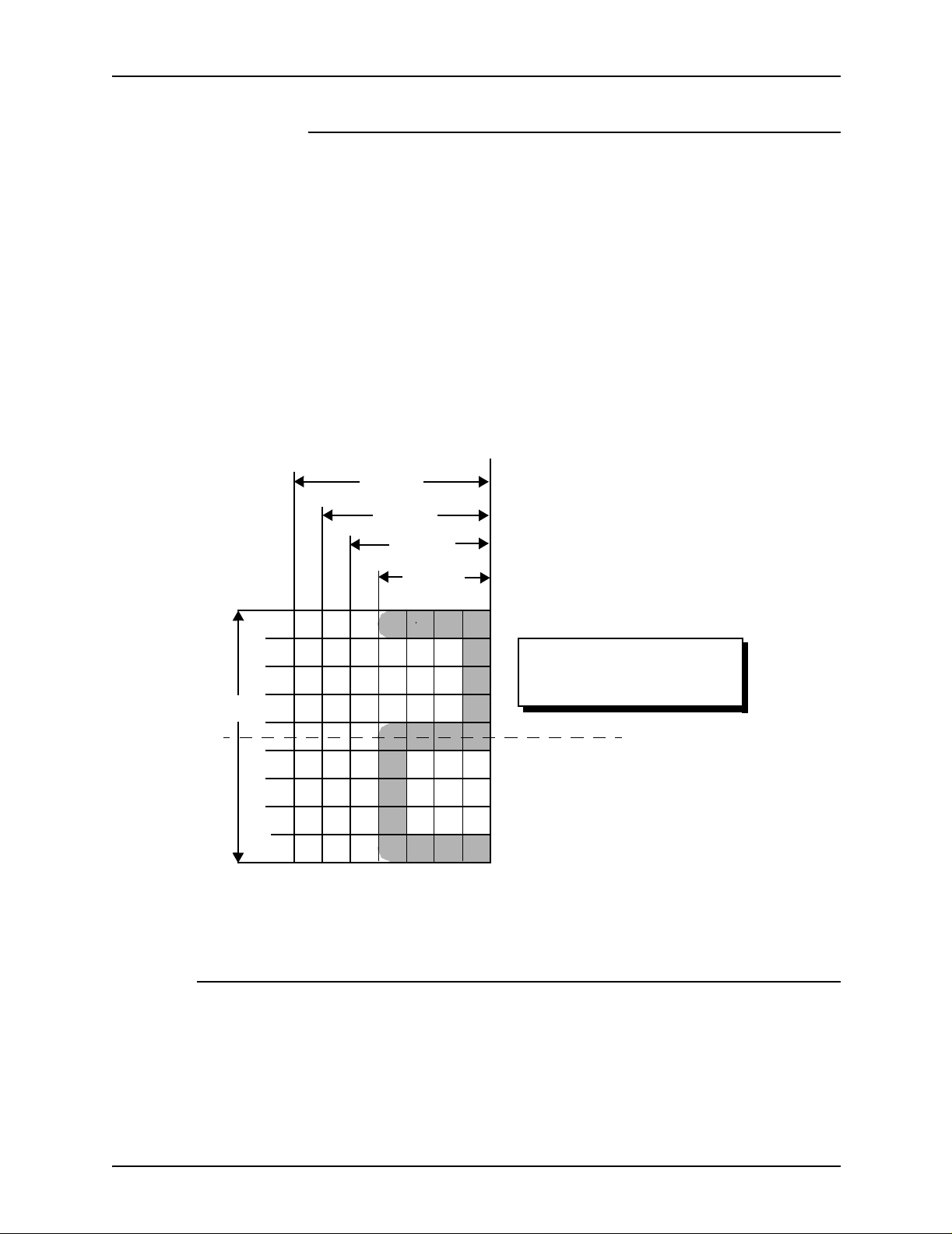
Document design
E13B character design
All of the E13B characters are designed on a 7 by 9 matrix of
0.013 inch/0.33 mm squares (see figure 4-5.). The minimum
character width is four squares (or 0.052 inch/1.3 mm) for the
numbers 1 and 2. The maxi mum width is 0.091 inch/ 2.3 mm for
the number 8, 0, and four special symbols. All charact ers except
the On-Us and Da sh symbols hav e a height of 0.117 in ch/3 mm.
This does not corres pond to an exact point size usually specifie d
for fonts, but is between 8 and 9 points.
The height of the On-Us symbol is 0.091inch/2.3 mm, and the
dash is 0.052 inch/1.3 mm. Both heights are multiples of the
basic 0.013 inch/0.33 mm unit.
0.117 in.
0.091 in.
0.078 in.
0.065 in.
0.052 in.
Figure 4-3. E13B character matrix design
For characters 0, 8, and symbols
For characters 4, 6, 9
For characters 3, 5, 7
For characters 1, 2
This is a 7 by 9 matrix of
0.013 inch/0.33 mm squares
Note:
1. All characters are centered around a
horizontal center line.
2. All characters are right aligned.
3. Minimum height of right edges is
0.052 inch/1.3 mm.
Field formats—E13B font
The MICR line contains up to 65 character positions. These
positions are numbered and grouped into five fields, which are
read from right to left.
Generic MICR Fundamentals Guide 4-9
Page 56

Document design
1. Amount
2. On-Us
3. Transit
4. External processing code (optional)
5. Auxiliary On-Us (optional)
All checks have at least three of the fields (Amount, On-Us, and
Transit). Commercial checks may also have an Auxiliary On-Us
field, located on the left of the ch eck. Some checks also have an
External Processing Code (EPC) digit, located between the
Transit and Auxiliary On-Us fields.
The Amount and Transit fields have a standardized content,
while the contents of the On-Us and Auxiliary On-Us fields can
vary to meet the individual bank requirements. The following
figure illustrates the placement of the four fields on a check in the
U. S.
Transit Number field
On-Us fieldAuxiliary On-Us field
Amount field
(blank at time of printing)
Figure 4-4. MICR line fields
4-10 Generic MICR Funda m entals Guide
Page 57

Document design
Document Specifications form
For accurate formatting of the entire MICR line, each bank
should provid e a MI CR D ocument Specifications form to identify
the proper contents of the various character positions. (Refer to
figure 4-4). The MICR Document Specifications form includ es:
• The account number, title, and address
• General specifications regarding c heck size and format
• The position of the control characters and digits that will be
entered into the routing field
• The structure of the On-Us and Auxiliary On-Us symbols
• General specifica tions regarding the quality control
procedures of the bank
Each MICR symbol, and the numbers or spaces between those
symbols, must be properly registered so that the fields do not
flow into one another.
The exact field structure depends on the national standards.
Field lengths may vary as a function of the national requirements
and even the detail usage of the symbols may be different. For
example, although Australia uses the same length and
bracketing structure for the Amount field as the U. S., their
“starts” are equivalent to the Transit field with a Transit symbol,
but they “close” with an On-Us symbol.
Even within the national standards, variation can exist within
fields. It is always best to identify the required field structure
through the use of the bank's MICR Document Specifications
form for a specific account.
Generic MICR Fundamentals Guide 4-11
Page 58

Document design
Figure 4-5. MICR Document Specifications form (U. S.
example)
NOTE: In this example, X denotes blank spaces required by the
issuing bank.
4-12 Generic MICR Funda m entals Guide
Page 59

Document design
Amount field
The Amount is the first field on the right, located between
character boxes 1 and 12. When this field is used, position 12
contains the Amount field symbol, and positions 2 through 11
contain the actual amount. The amount is right-justified, and all
unused positions to the left are filled in with zeros.
The Amount field is usually empty when the document is printed;
the amount is added later by the bank. However, some
applications may add the Amount field while printing checks.
On-Us field
The second field from the right is the On-Us field, located
between character boxes 14 and 31. It follows a blank space at
position 13, which is a separator from the Amount field.
The On-Us field includes variable information from the banking
institution, including the account number. It contains the On-Us
symbol, at position 14 and 31 or 32.
To the left of the On-Us sym bol, readin g right to left as the rea der
sorter does, are the account number, the bank branch number,
and the check number. The check serial number is typically to
the right o f the On-Us symbol. Since the issuing institution
determines the content of the On-Us field, the bank branch on
which the check is drawn on may also be indicated. The last
position is usually followed by a blank in position 32.
The Dash symbol is sometimes used as a separator within the
On-Us field. This is not recommended, however, because the
dash is difficult to detect.
Trans it field
The Transit field is located between character boxes 33 and 43.
The Transit symbol is located at po sitions 33 and 43. On a check
having four fields, like the one in figure 4-3, this field is second
from the left. How e ver, shorter checks (such as personal checks)
do not have an Auxiliary On-Us field. In this case, the Transit
field is the farthest left of the three fields. The Transit field, like
the Amount field, is right-j ustified, wi th all unu sed positions to th e
left filled with zeros.
Generic MICR Fundamentals Guide 4-13
Page 60

Document design
External processing code (EPC) field
The External Processing Code (EPC) field is an optional field
between the Transit and Auxiliary On-Us fields at position 44 or
45. When present, this field indicates that the document is
eligible for special processing.
Auxiliary On-Us field
The Auxiliary On-Us field is an optional field that is sometimes
used by the banks for additional processing information or high
value serial numbers. When it is present, it is the farthest left on
the check, between positions 45 or 46 through 65.
This field is not present on personal checks because of space
limitations. On business checks, it usually contains the check
serial number or accounting control information specific to that
account.
Field formats summary
The following table provides a summary of the MICR field
formats and character positions using the E13B font.
4-14 Generic MICR Funda m entals Guide
Page 61

Document design
Table 4-1. MICR field formats—E13B
Field Position Description
Amount 1 to 12 Fixed field signifying the dollar value of the check.
Position:
• 1 Opening amount symbol
• 2 to 3 Cents
• 4 to 11 Dollars (zero-fill to left)
• 12 Closing amount symbol
• 13 Space
On-Us 14 to 31 or 32Content is determined by each institution; generally contains the
account number. May optionally extend to include position 32. May also
contain the serial number, the transaction code, or both. The symbol
located nearest to the left edge of the document, must end more than ¼
inch/6.35 mm from the left edge of the document.
Position:
• 14 On-Us symbol
• 15 to 31 or 32 Generally contains the account number, and may
also contain the serial number, transaction code, or both.
• 31 On-Us symbol if not used to extend the field
• 32 Space, or On-Us symbol if the field was extended
Transit 33 to 43 Fixed field identifying the institution upon which the check is drawn.
Position:
• 33 Opening transit symbol.
• 34 Check digit. This number combined with the first eight digits
verifies the accuracy of the routing number in computer processing.
• 35 to 38 Institutional identifier (a four-digit check routing symbol).
• 39 to 42 Check routing symbol. The first two digits are the federal
reserve district for the institution. The third digit identifies the federal
reserve office (the head office or branch) or a special collection
arrangement. The fourth digit shows the state for the institution, or a
special collection arrang ement.
• 43 Closing transit symbol.
External
Processing
Code (EPC)
44 or 45 External Processing code (EPC) field. If present, represents
participation in an authorized program that requires special handling or
processing in the collection system.
Auxiliary On-Us
(optional)
45 or 46 to 65Content determined by each institution. Contains numbering,
transaction codes, and internal controls. Used only for checks longer
than 6 inches/152 mm). The right most symbol must start within ¼ inch/
6.35 mm of the Transit symbol farthest to the left.
Generic MICR Fundamentals Guide 4-15
Page 62

Document design
Character alignment
CMC7 font
The bottom edges of adjacent E13B MICR characters within the
same field are in alignment within:
• ± .007 inch/0.18 mm (CPA—Canada)
• ± .015 inch/0.38 mm (ISO—International)
• ± .030 inch/0.76 mm (ANSI—U. S. only)
Although this is a concern for impact printing, MICR characters
printed on laser systems are always properly aligned.
NOTE : The Amount field of the MICR l ine is not no rmally printed
by the laser printer, but is added by a proof machine at the bank
of first deposit. The proof machine, being an impact device, may
cause alignment errors.
The CMC7 font is an alternative MICR font that has been
adopted in various countries throughout the world.
CMC7 numbers and symbols
The usage of the CMC7 special symbols generally parallels the
usage of the E13B special symbols. There are, however,
significant differences.
Figure 4-6. CMC7 MICR font character set
4-16 Generic MICR Funda m entals Guide
Page 63

Document design
The CMC-7 font consists of 10 numeric characters (0-9), five
special symbols, and 26 alphabetic characters (A-Z). The five
special symbols are illustrated in the following figure:
Figure 4-7. CMC7 special symbols
S-1: Indicates the start of the bank's internal information
(account number, etc.). Although it serves a purpose similar to
the E13B On-Us symbol, it is not used in the CMC7’s equivalent
to the E13B Auxiliary On-Us field.
S-2: Identifies the start of the Amount field. Unlike the E13B
structure, this symbol is not used to terminate the Amount field.
The CMC7 Amount field terminates when the appropriate
number of digits (minimum 10, maximum 12, followed by a
blank) have been detected.
S-3: Used as the terminator for the bank routing information. It
also functions as the terminator of the check number field
(following a minimum of four digits, maximum of seven digits).
S-4: Not used. Although its structure is defined, this symbol
usually does not appear in the structure of the MICR line.
Generic MICR Fundamentals Guide 4-17
Page 64
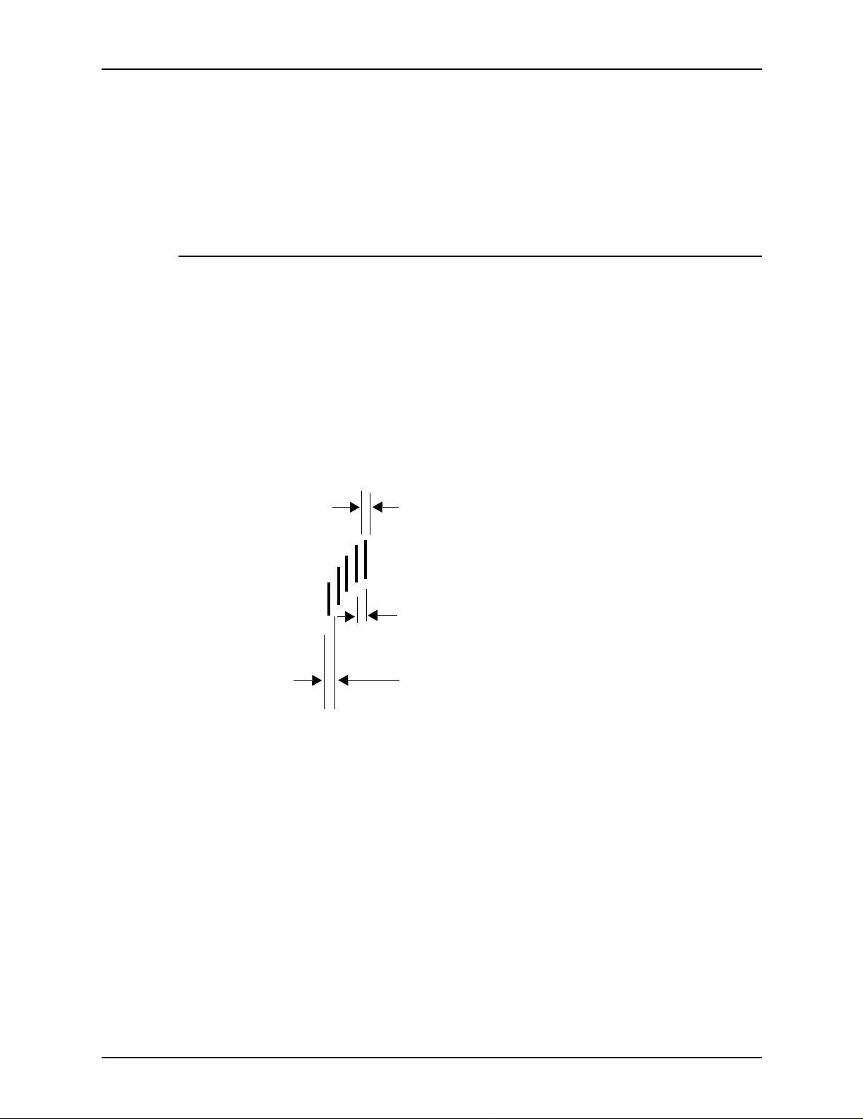
Document design
Character design
S-5: Indicates the ro uting numb er that identifi es the institut ion on
which the check is drawn and where the document shou ld be
sent for processing. This symbol is the equivalent of the E13B
Transit symbol. However, it is not used to terminate the bank
routing identification.
The CMC7 font differs from the E13B font in character height
and width. The height of all of the numeric characters is 0.112
inch/2.85 mm. Special symbols are 0.106 inch/2.70 mm. Unlike
the E13B font, the CMC7 characters all have the same width.
Each CMC7 character format consist of seven vertical strokes
separated by six spaces of 0.3 or 0.5 mm ( r eferred t o as short
and long intervals). Each character contains two long in terv als
and four sho rt intervals. Different permutations of the long and
short intervals identify each character.
Stroke width: The difference between the right
edge and the left edge of a stroke is 0.004 to 0.007
inch/0.10 to 0.19 mm.
Short interval:.3 mm. The distance between
the right edges of successive strokes is 0.0096 to
0.0144 inch/0.24 to 0.36 mm.
Long interval: The distance between the right
edges of successive strokes is 0.0176 to 0.0224 inch/
0.44 to 0.56 mm.
Figure 4-8. CMC7 stroke and interval dimensions
The fonts are optimized for each product. They are not
interchangeable between products.
4-18 Generic MICR Funda m entals Guide
Page 65

MICR character spacing requirements
Reader sorters have timing limit s that prevent them from
handling extreme variations in character spacing. The average
spacing requirement for MICR characters is 0.125 inch/6.4 mm
per character (8 characters per inch).
The MICR specifications have a tolerance on the 0.125 inch/6.4
mm spacing requirement of ± 0.010 inch/.3 mm. Specifications
also state that the accumulated error must not exceed field
boundarie s, shown in table 4-1. MICR characters are right
justified and the numbers are read from right to left. This means
that you might need to pad the MICR line with leading blanks so
that the numbers start in the correct position.
Character spacing algorithm for 300 dpi
Document design
MICR printing systems print at 600 or 300 dots per inch. At 600
dpi, there are no issues with character spacing. 600 dpi can be
divided evenly by 8 characters per inch, resulting in 75 dots per
character.
Howe ver, 300 dpi, when di vided b y 8 char ac ters p er inch , results
in 37.5 dots per char acter. The system cannot print half a dot, so
it cannot print each character at exactly 8 characters per inch.
You can achieve an average of 37.5 dots per character by using
a proportional spaced f ont wit h a spacing al gorithm that places a
space of one dot after every second character. In other words,
two characters of 37 dots are printed, followed by a one-dot
space, then the sequence is repeated. This algorithm is used
extensively in high volume printing installations.
Fixed pitch and proportional font spacing
The relationship between the input character and the out put
character or spac e is shown for proportional spaced fonts in
table 4-3, and for fixed pitch fonts in table 4-4.
NOTE: The relationship between the input character and the
output character may differ slightly from these tables for some
Xerox MIC R products . These di ffer ences are primarily f oun d with
the revision control character (?) and the special symbols.
Generic MICR Fundamentals Guide 4-19
Page 66

Document design
The following HP PCL escape sequences must be entered
exactly as shown to select the Xerox MICR fonts:
• E13B:
<ESC>&100<ESC>(0U<ESC>(s0p8.00h9.00v0s0b0T
•CMC7:
<ESC>&100<ESC>(1U<ESC>(s0p8.00h9.06v0s0b0T
NOTE: The PCL 5 font rotation commands are used to rotate
the E13B and CMC7 portrait fonts fo r landscape applications.
Table 4-2. PCL fixed pitch MICR font characteristics
File name E13B-P.FNT CMC7-P.FNT
Orientation Portrait Portrait
Symbol set OU 1U
Pitch Fixed Fixed
HMI 8.00 CPI 8.00 CPI
Point 9.00 9.06
Style Upright Upright
Stroke weight 0 0
Type face Line printer Line printer
4-20 Generic MICR Funda m entals Guide
Page 67

Document design
Table 4-3. Character conversion and spacing of proportionally spaced MICR
fonts (LCDS printing only)
Input character
ASCII symbol
(space) 20 (space) 37 (space) 37
! 21 (space) 1 dollar symbol 37
$ dollar symbol 37 dollar symbol 37
030037037
131137137
232237237
333337337
434437437
535537537
636637637
737737737
838837837
939937937
: 3A Transit symbol 37 S-1 symbol 37
; 3B Amount symbol 37 S-2 symbol 37
< 3C On-Us symbol 37 S-3 symbol 37
= 3D Dash symbol 37 S-4 symbol 37
> 3E (not used) -- S-5 symbol 37
A 41 (space) 1 (space) 1
B 42 (space) 2 (space) 2
C 43 (space) 4 (space) 4
D 44 (space) 8 (space) 8
E 45 (space) 16 (space) 16
F 46 (space) 32 (space) 32
G 47 (space) 64 (space) 64
X (space) 37 (space) 37
Y (space) 38 (space) 38
a Amount symbol 37 (not used) -d Dash symbol 37 (not used) -o On-Us symbol 37 (not used) --
t Transit symbol 37 (not used) -z On-Us symbol 37 On-Us symbol 37
? revision control
Input code
Hex Value
E13B font CMC7 font
Printed result Dot width Printed result Dot width
37 revision control
character
character
37
Generic MICR Fundamentals Guide 4-21
Page 68

Document design
Table 4-4. Character conversion and spacing of fixed pitch MICR fonts at 300 dpi
Input character
space (space) 37.5 75 (space) 37.5 75
$ dollar symbol 37.5 75 dollar symbol 37.5 75
0 0 37.5 75 0 37.5 75
1 1 37.5 75 1 37.5 75
2 2 37.5 75 2 37.5 75
3 3 37.5 75 3 37.5 75
4 4 37.5 75 4 37.5 75
5 5 37.5 75 5 37.5 75
6 6 37.5 75 6 37.5 75
7 7 37.5 75 7 37.5 75
8 8 37.5 75 8 37.5 75
9 9 37.5 75 9 37.5 75
: Transit symbol 37.5 75 S-1 symbol 37.5 75
; Amount symbol 37.5 75 S-2 symbol 37.5 75
< On-Us symbol 37.5 75 S-3 symbol 37.5 75
= Dash symbol 37.5 75 S-4 symbol 37.5 75
> (not used) -- -- S-5 symbol 37.5 75
a Amount symbol 37.5 75 (not used) -- -d Dash symbol 37.5 75 (not used) -- -o On-Us symbol 37.5 75 (not used) -- --
t Transit symbol 37.5 75 (not used) -- -z On-Us symbol 37.5 75 On-Us symbol 37.5 75
? revision control
E13B font CMC7 font
Printed result
character
Dot width
@300 dpi
37.5 75 revision contr ol
Dot width
@600 dpi Printed result
character
Dot width
@300 dpi
37.5 75
Dot width
@600 dpi
4-22 Generic MICR Funda m entals Guide
Page 69

Check size
2.75 inches/
70 mm
Document design
The ANSI specified size limits for a check are shown in the
following figure.
Length: 6 inches/152 mm minimum
8.75 inches/222 mm maximum
Height: 2.75 inches/70 mm minimum
3.67 inches/93 mm maximum
6 inches/
152 mm
Minimum size document
Most personal checks in the U. S. use the minimum size
requirements. Commercial checks vary in size; however, most
are closer to the maximum requirements.
Although the above dimensions are limited to U. S. standards,
each national standards organization has established the
minimum and maximum size documents that are used in their
jurisdictions, shown in the following table. The bank's MICR
Document Specificat io ns form usually provid es the defini ti ve
guide regarding t he document sizes.
3.67 inches/
93 mm
Maximum size document
8.75 inches/
222 mm
Figure 4-9. Check size limits
Generic MICR Fundamentals Guide 4-23
Page 70
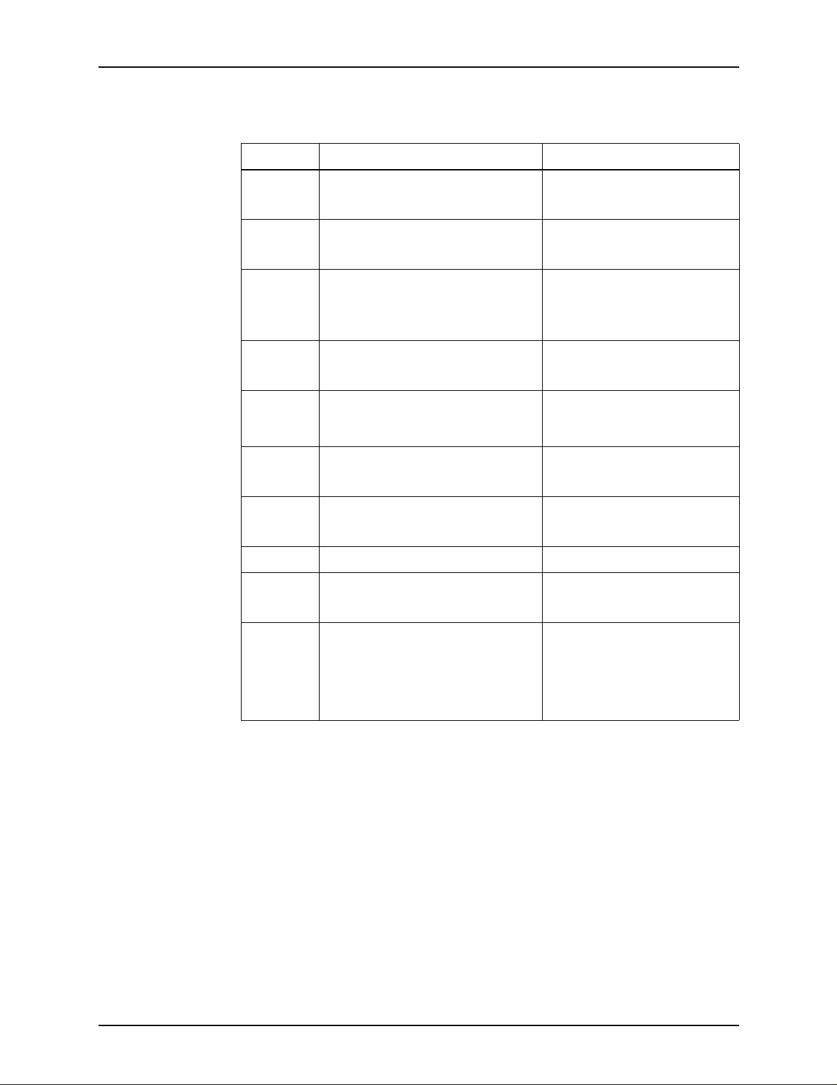
Document design
Table 4-5. Check dimensions summary chart
Country Check dimensions Notes
Australia 6.25’’ x 2.75’’/162 x 70 mm (min.)
8’’ x 3.66’’/203 mm x 93 mm (max.)
Bermuda 6.125’’ x 2.75’’
7.4’’ x 3.15’’
Brazil 175 mm x 80 mm Typically 4 checks per 8.5 x 12’’
Canada 6’’ x 2.75’’ (min.)
8.5’’ x 3.66’’ (max.)
France 175 mm x 80 mm Check booklet: 225 mm x 80
Hong Kong 7’’ x 3.25’’
8.5’’ x 3.5’’
Italy 180 mm x 72 mm (min.)
260 mm x 72 mm (max.)
Spain 175 mm x 80 mm 175 mm x 100 mm with top stub
Typically 8’’ x 3 5/8’’
10.5’’ x 3.15’’ with stub
sheet if check has stub;
otherwise 4 checks per 7.25 x
12’’ sheet
Typically 6 1/4’’ x 2 3/4’’
mm, 102 mm x 175 mm, and
225 mm x 102 mm
UK 6.125’’ x 2.75’’/155 x 102 mm (min.)
8.25’’ x 4’’/209 x 101 mm (max.)
USA 6’’ x 2.75’’ (min.)
8.75’’x 3.66’’ (max.)
Typically 8’’ x 3’’
Typical personal check:
6’’ x 2.75’’
Typical commercial check:
8.5’’ x 3.67’’
4-24 Generic MICR Funda m entals Guide
Page 71

Other application considerations
Printing on a Xerox MICR printing system raises some a dditional
application con s id erations.
T wo sided printing
Two sided (duplex) printing may be used in a MICR application,
but the forms design and the application structuring require care.
• The reverse side of the clear band must not contain any
magnetic printing. The only magnetic printing that is
permitted in the clear band on either side of the sheet is the
MICR line.
• The MICR line should be printed on the first imaged side of
the duplex sheet.
Document design
• The endorsement a rea on the bac k of the chec k mus t be ke pt
free of any printi ng that would interfere with bank
endorsements.
NOTE: This information is applicable only if your system
supports duplex printing.
Perforations
If you are using perforated forms, the perforation must not
interfere with the clear band area. Therefore, it should not be
underneath the MICR line. Refer to “Perforation” in chapter 3,
“Paper facts,” for guidelines for using per forations.
Multiple-up printing
For a check printing operation, several check documents can be
printed on each sheet. This is called “multiple-up” or “multi-up”
printing, which means that on e or more logical pages ar e printed
on one physical page. Perforated paper is often used to separate
the documents or they may be separated after printing by gangcutting or slitting the sheets.
The following figure shows some possible sheet layouts for
multiple- up prin ting.
Generic MICR Fundamentals Guide 4-25
Page 72

Document design
Document
Stub
Stub
Document
Document
Stub
Document
Stub
Four-up with check register
Stub
Document
Stub
Document
Document
Document
Document
Three-up with no stub
Stub
Document
One-up with stub*Two-up with stub
*The maximum check height is 3.67 inches/93 mm, or one-third
of an 8.5 by 11 inch/216 x 279 mm sheet.
Figure 4-10. Sheet layouts for 8.5 by 11 inch or A4 paper
A multiple-up format, however, raises the following application
considerations.
• Avoid multiple-up applications in which the last sheet is only
partially filled.
Example: In a 3-up check application that will print 100
checks, the last page of the job prints only one check. This
would leave the remaining two checks on the form blank.
Blank checks on the last sheet are not acceptable.
Potential solutions include:
– Ensure there is always enough data to fill the la st page,
with partial pages being “voided” by the data.
– Design more than one form when the correct form is being
selected for the final page by the software program.
• Problems can occur when the sequence of the printed
application does not meet the requirements of the site
finishing equipment.
4-26 Generic MICR Funda m entals Guide
Page 73

Readability
Document design
Example: A 3-up a pplica tion is p rinted with chec ks num bered
1 through 6, in that order. After they are cut, three stacks of
finished checks are produced: the first with check numbe r s 1
and 4, another with numbers 2 and 5, and a third with
numbers 3 and 6. For this situation, the host application may
need to be adjusted to enable the proper sequence to be
maintained during fi ni shi ng .
NOTE: For appropriate page sizes, refer to the printer
documentation.
When designing MICR documents, it is critical to remember that
the document acts as a v e hicle to tr ansfer money from one party
to another. The MICR document must clearly communicate the
information required to complete that transfer, without
interference from colorful backgrounds or confusing layout.
Digital image capture, processing, and storage for the entire
check make this requirement more important.
Work is in progress to make the digital image of a check legally
binding when captured and processed by banks. This is
necessary to permit truncation of the paper documents early in
processing and eliminate the cost of transporting the paper to the
issuing bank. Checks should be designed to be easily
interpreted when digitized into black and white images.
MICR documents are not the only documents in which
readability is a concern. Many payment processing systems are
designed to use an OCR-printed turnaround document to direct
a check based payment. In these cases, readability of the OCR
line may be compromised if the document is print ed using
magnetic ink. The processing system detect checks by the
presence of magnetic ink and initia te an E13B font recognition
routine. If the turnaround document is magnetic, failure to read
would result. Therefore, MICR printers are not recommended
when an OCR font is used for data collecti on.
Generic MICR Fundamentals Guide 4-27
Page 74

Document design
4-28 Generic MICR Funda m entals Guide
Page 75

5. Document processing
The life cycle for a MICR document involves three types of
processing equipment:
• Proof machin e
• Reader sorter
• Repair station
Proof machine The proof machine transfers the amount from the Convenience
Amount field to the MICR encoded Amount field. It prints the
Amount field onto the ch ec k using either a thermal transfer or an
impact ribbon printer. The proof machine may be manually
operated or automated using a scanner and character
recognition tech nol o gy .
Reader sorter The checks are then sent through a series of reader sorter
passes. The reade r sorter inputs data fr om th e ch ecks, captures
each check image, endorses the checks, and sorts them
according to their destination.
The checks are separated into either “transit items” drawn on
other banks or On-Us items, drawn on the processing bank.
Transit items are segregated into different groups and may
receive several reader sorter passes, depending on the
destination.
Repair station If an error occurs in the reader sorter, the document usually goes
to a repair station. Here, the MICR line is read both magnetically
and optically, with operator intervention in severe cases. A new,
corrected MICR line is applied to the check.
The final measure of the quality of the MICR document is how
well it passes through the au tomated payment processing
system.
Generic MICR Fundamentals Guide 5-1
Page 76

Document processing
Proofing checks
Amount determination errors
All checks start automated processing in the Proof of Deposi t
department. Check processing relies on a series of debits and
credits throughout the process to identify errors as close to the
source as possible.
The first step is t o pro ve that the deposit is vali d. A d eposit sli p is
balanced again st the value of the items deposited with it. Errors
in MICR amount encoding or deposit ticket completion show up
as a failure to balance.
To encode the amount, an operator may read the check and
manually enter the amount, or an automated scanner may
capture and analyze an image of the check to determine the
correct MICR Amount field content. Poorly designed checks may
interfere with amount determination in the following ways:
• Non-standard amount location
• Amount value written too small or too large
• Interference of check background design elements with
amount field identificatio n
• Lightly written check amounts
• Use of colored inks that do not provide sufficient contrast
Whenever the value of the check cannot be quickly and
accurately determined, the cost of processing the item
increases. The bal ancing process continu es throughout pa yment
processing, but th e impact of check design most critical here.
Proofing equipment errors
Another potential problem in proof encoding is compatibility of
the laser printed check with the encoding equipment. For many
years, all proofing equipment used imp act ribbon technology,
which proved to be stressful for matrix head reader sorters (see
next section).
5-2 Generic MICR Fundamentals Guide
Page 77

Non-impact ribbon technology offers higher encoding speed and
fewer matrix read processing issues. However, problems occur
with transfer of ink to the paper. Paper roughness must be
controlled. Also, for MICR laser printers, which apply a release
agent or oil to the fuser, the specified fuser agent must be used
and the metering system maintained according to Xerox
schedules.
Reader sorter function
Reader sorters are machines that read magn etic ink characters
that are printed using the E13B or the CMC7 fonts. Reader
sorters recognize the magnetic waveform of the character, its
magnetic pattern, its visual pattern (using OCR), or a
combination of these characteristics. Reader sorters can be
programmed to validate and sort by specified MICR line data
fields. They may also be capable of endors ing, microfilming,
imaging, and providing processing information in hardcopy.
Document pr ocessing
How well the document passes through the reader sorter
depends of the following:
• Document characteristics
– MICR line format and placement
– Print quality
– Magnetic signal strength of the image
– Paper characteris tics.
• Reader sorter characteristics
– Reader sorter type
– Setup adjustments
– Quality and quantity of operator maintenance.
– Operation of the reader sorter
• Damage resulting fro m prior processi n g
– Handling damage
– Lead edge fluff
Generic MICR Fundamentals Guide 5-3
Page 78

Document processing
Waveform generation
All types of reader sorters react to any magnetic material in the
clear band, intentionally placed on a document or not.
Reader sorters read from right to left and the magnetized ink
generates a waveform. The following figure illustrates the
process.
Figure 5-1. On-Us symbol waveform reading
First, the character is magnetized by the reader sorter. Then, as
the character pa sses the read h ead, edg e A gener ates a change
in magnetic flux, produ ci ng pea k A of the w aveform. There is no
change in flux as the character between A and B passes the
head. As edge B passes the head, a change in flux is sensed
producing p eak B of the waveform.
This continues through edges C, D, E, and F, producing the
entire waveform.
5-4 Generic MICR Fundamentals Guide
Page 79

Types of reader sorters
The following recognition technologies have been incorporated
into MICR reader sorter devices.
Waveform reader sorters
Wa vef orm reader sorters measure the magnetic signal wav ef orm
or pattern of the MICR character as the documents pass the
read head. Waveform reader sorters are often referred to as
“single slot” or “single gap” readers because the read head
contains one magneti cally sens itiv e slot o r gap , which co v ers th e
height of the entire ch aracter string in the clear band. Each MI CR
character that passes the re ad slot produ c es a waveform signal.
This signal is compared against the known waveforms of the
MICR character set to determine which character was read.
Document pr ocessing
Waveform reader sorters are also called “DC readers,” because
they use a constant magnetic field to magnetize the characters.
Waveform reader sorters are generally low to medium speed
reading devices. The reject rates for these readers is slightly
higher than for matrix readers.
Matrix or AC reader sorters
Matrix readers use a series of small r ead h eads tha t are stac k e d
in close proximity, each of which reads a small strip of the
character string. The segments of the MICR characters register
as binary magnetic flux transitions at each read head. These
pulses are combined and used to build a two dimensional bitmap
for each character. This bitmap is then compared to known
bitmap patterns to determine the identity of the character.
To simplify bitmapping, readings from groups of heads are
logically combined to produce a single value. This slightly
increases sensitivity to spots, but results in lower reject rates for
matrix readers.
Matrix readers are also called “AC readers,” because they use
an oscillatin g magnetic field to magnetize the characters. These
oscillations cause a seri es of waveform pe aks in a character
stroke, which are recorded as a binary 1 in the bitmap image of
the character.
Generic MICR Fundamentals Guide 5-5
Page 80

Document processing
Optical reader sorters
Dual read magnetic reader sorters
Optical readers typically use a light source and some type of
photosensitive matrix array to convert an image of the character
into a set of electrical signals. Optical readers that can interpret
the characters can be used to input data into an automated
reading system. They are frequently used in reject repair
equipment.
Some reader sorters use a dual read approach, in which two
read stations magnetize and read the entire clear band area of
the document independently.
The simplest dual read reader sorter uses two waveform
readers. Like single read waveform reader sorters, each MICR
character that passes through the read slot produces a
waveform signal at each read station. The waveforms are
compared against the known waveforms of the MICR character
set, using different algorithms and circuitry in each station, to
determine which character was read.
Another type of dual read reader sorter has one single slot
waveform read station and one matrix head read station. The
single slot reader compares the waveforms against the known
MICR character wav ef orms, and the matrix re ader buil ds a digital
bit map for each character and compares that to known
character bitmaps.
With the dual read technology, the system compares the results
of the first head read with those of the second. If a character can
be interpreted by only one of the read stations, the successful
reader result is used. If neither read station properly identifies a
character, that character is rejected. Conflicting interpretations
between the two heads al so cause s character rejection.
An important aspect of reject rate diagnosis i s understanding the
recognition mode used by a dual-read reader sorter. Processing
performance sh ould be e v aluat ed only i n dual-re ad mode . Use of
diagnostic settings to turn off one of the read stations, or to reject
on either station independently, inflates the repo rted reject rate.
5-6 Generic MICR Fundamentals Guide
Page 81

Hybrid magnetic and optical reader sorters
Hybrid reader sorters use two read technologies:
• Magnetic waveform recognition
• Optical character recognition
Compared to other types, hybrid reader sorters have very high
accuracy rates, because they interpret and compare the results
produced by the magnetic waveform recognition and the optical
character recognition. If a character cannot be interpreted by
MICR waveform analysis, the system takes the results of the
optical recogn ition. In diagnostic situations, understanding the
recognition mode is important.
Another f orm of h ybrid equip ment, used primarily in loc k bo x an d
remittance processing, uses optic al and magnetic recognition in
a fundamentally different way that can cause problems with
MICR documents. Th ese reader so rters process an OCR printed
turnaround document, followed by a MICR printed check. They
identify a chec k by the p resence of ma gnetic ink, t hen s witch to a
MICR font recognition system. If the turnaround document is
printed with an OCR font but uses MICR ink, it may be
misidentified and rejected, although the OCR font is properly
printed.
Document pr ocessing
Processing speeds
Reader sorters are availab l e in a v ariety of siz es and pro cessing
speeds. The smallest can fit on a desk top; the largest may be
the size of a mainframe computer. Performance may be
categorized as low, medium, or high speed.
The speeds may be defi ned as follows, ba sed on the speed of
handling a 6 inch/152 mm long document:
Low speed: Process 100 to 750 documents per minute. These
machines are usually found in small banks or are used fo r
handling small volumes of checks. They use waveform
recognition.
NOTE: Proofing devices also process documents at these
speeds. Although these devices can operate in reader sorter
mode, they may not have automatic document handlers and
require manual hand feeding.
Generic MICR Fundamentals Guide 5-7
Page 82

Document processing
Medium speed: Process 1,000 to 1,500 documents pe r m inute.
These machines usually use waveform recognition, frequently
with dual or hybrid read.
High speed: Process 2,000 or more documents per minute.
These machines are typically found in larger banks,
clearinghouses, processing centers, etc. They generally use
matrix or dual read technology.
Paper handling by reader sorters
Reader sorters are designed to handle batches of check
documents of mixed sizes, weights, and conditions (pieces torn
away, creased, etc.), at high speed. This may result in reader
sorters handling documents somewhat roughly.
Documents may undergo from 10 to 20 separate passes through
reader sorters. If the leading edge of a check is damaged slightly
in one of these passes, repeated sorting can increase the
damage until the docu ment no longer f eeds p roperly. Because of
the high cost of handling misfeeds, check processors limit the
types of paper that can be used to print MICR documents.
Reader sorters typically use the following mechanisms to handle
MICR documents.
Hopper jogger
The hopper jogger is usually least stressful to documents. It
vibrates the documents to aid in aligning and separating them.
Separator
A picker belt forces the first document forward, while a restraint
system retards the remainder of the documents. The initial
shearing force and acceleration applied to t he doc um en t is
generally followed by a deceleration as the document is fed into
a multiple-documen t detection statio n.
If the forces are too extreme, or the document is too weak, the
document could collapse, causing wrinkles. Wrinkles normally
appear in the Amount field.
5-8 Generic MICR Fundamentals Guide
Page 83

Aligner
Within the aligner, a series of wheels drive the bottom edge of
the document toward the back side of the reader sorter so that
the MICR line is in a predicta ble location. The wheels hav e a
series of plastic fingers that make contact with the back side of
the document and force it against the aligner drum.
Read/write heads
A wheel with a v ery short nap bristle brush on its surface presses
the document first against the write head, then against the read
head. In orde r to optimize the pressures for handling debossed
characters and fol ded documen ts, the h ead ma y be p ositioned at
a sharp angle. Material can be scraped off the document and
spread out by the bristled wheel pressing on the paper.
If the wheel is worn, the spread i ng or scraping processes could
be unev en, r esulting i n a lump of m aterial being r edeposited on a
later document.
Document pr ocessing
NOTE: This process is typical only of IBM 3890 matrix reader
heads. Other reader sorters may differ in several details.
Item numbering and endorsing stations
After the document is read, belts carry it through item numbering
and endorsing stations .
If certain plates or document guides in these stations are
misaligned, docu ment abrasion could occur here.
Microfilm or image capture unit
Optionally, the document may enter a microfilm or image
scanning unit . In the IBM 3890, the document is he ld to a plate
by a vacuum and driven by a toothed belt that is in the center of
the plate. The edges of the plate, the belt-slot, or the teeth may
be sharp enough to scrape the document surface.
Generic MICR Fundamentals Guide 5-9
Page 84

Document processing
Sorter pockets
Reject repair
The document finally arrives at a diverter plate, which sends it
into the pocket that the reader sorter program sele cts based on
the MICR line data. The pocket has a pair of metal springs that
press the document onto the stack that is in the pocket.
If the poc k e t i s em pty, the document ma y impa ct ag ainst the r ail s
at the bottom of the pockets with greater than normal velocity.
Short-grain docume nts are especia lly vuln erab le to leadin g edge
damage from this impact, and layers of paper may separate a
small amount on each pass. After multiple passes, this can
cause lead edge fluff.
If a MICR document cannot be read or is badly damaged in
processing, it goes to a reject repair station. Here, it is read
again, using low speed optical and magnetic read stations and
operator intervention when th ese read stations fail to recognize
all the characters. A similar process is also used for return
processing of rejected items.
After the correct M ICR line encod ing is determined, a repair strip ,
encoded with the information that the processing bank requires,
is added to the bottom. In effect, a new MICR clear band is
added and encoded below the original one.
Figure 5-2. Check with reject repair strip
5-10 Generic MICR Funda m entals Guide
Page 85

Document pr ocessing
If the document is badly damaged, or if the processing center
does not have an automated repair station, a document carrier
envelope may be used. This is a check-sized, translucent
envelope designed to fully enclose a check while addi ng a new
MICR clear band and encoding area at the bottom.
In most cases, processing banks do not encode the full MICR
line on transit items. Instead, they encode only the routing
number and amount information that they need in order to pass
the document on. This means that when the issuing bank
receives the repaired document, it must remove the repair strip
and repeat the repair proce ss with al l fi elds encoded.
The reject repair process results in the issuing bank incurring
costs for rejects on any bank’s equipment, and is a factor in any
MICR quality issues that the bank raises du e to high reject rates.
Generic MICR Fundamentals Guide 5-11
Page 86

Document processing
5-12 Generic MICR Funda m entals Guide
Page 87

6. Quality control
MICR printing requires constant quality control. Special
equipment is required to produce quality documents that meet
the X9.27, X9.13, X9.7, and ISO 1004 specifications. You should
develop a formal quality control program to ensure that all check
printing specifications are met.
Key factors for producing good MICR documents include:
• High-grade xerographic print quality
• Good character uniformity when viewed with back lighting
• Few or no defects
• Good fusing
• Good paper quality mee ti ng xerographic and MICR
processing needs
• Good forms d esign
• Consistent printer maintenance
MICR documents should be printed only by operators who have
the proper knowledge and experience.
Print quality specifications
Banks use the following print quality specifications for MICR
characters:
• Horizontal posi ti o n
• Vertical position
•Skew
• Character-to-character spacing
• Character size
• Voids or deletions
• Extraneous ink or spots
• Debossment
Generic MICR Fundamentals Guide 6-1
Page 88
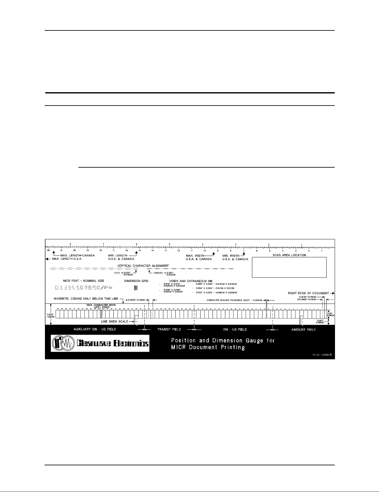
Quality control
• Magnetic signal strength
These are the ANSI print specifications for MICR. Other
countries that use MICR have similar specifications.
Optical tools used to check MICR
Although MICR documents may appear satisfactory to the
unaided eye, the MICR tools are required to determine if a
document is within specifications.
MICR Gauge
The MICR Gauge lets you compare the location of Xerox MICR
printed information to industry standards. The Gauge is printed
on a thin sheet of flexib le plastic , which is attach ed to the bo ttom
of a piece of h ard plastic. Slip the document that you are
evaluating between the two pieces of plastic.
Figure 6-1. Example of a MICR Gauge
6-2 Generic MICR Fundamentals Guide
Page 89
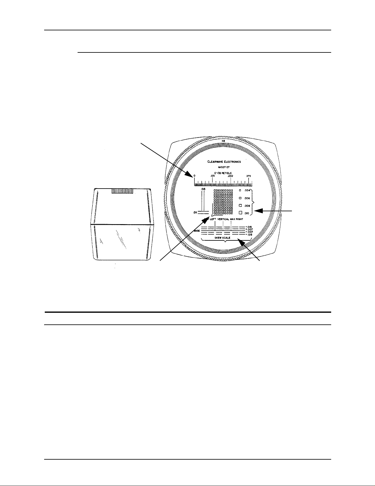
Small Optical Comparator
The Small Optical Comp arator also compares th e M IC R printin g
to industry standards (see the following figure). Its main
difference from the MICR Gauge is that the Comparator’s
nominal 8x to 12x magnification and built-in measuring scales
enable you to measure printing characteristics that require
greater precision.
Measures character-to-character spacing
Quality control
Measures
spots and
deletions
Measures character size
Figure 6-2. Small Optical Comparator
Magnetic testing equipment
Each MICR symbol and character has an ideal waveform and
nominal signal strength. Every MICR printing technology
modifies the waveform from the ideal in a different way, so that
the nominal MICR signal v aries some what among the chara cters
and symbols. These are characteristics of the printing
technology and font design, and cannot be adjusted in Xerox
MICR printers. For this reason, the signal strength of the On-Us
symbol is used as t he Xerox reference for the entire MICR line.
Measures character-to- c haracter
vertical variation: measures skew
Generic MICR Fundamentals Guide 6-3
Page 90

Quality control
MICR signal strength is the only magnetic specification in ANSI
standards. Magnetic testers are needed to identify magnetic
versus non-magnetic extraneous ink, and they can be useful in
interpreting waveform uniformity issues. All other standards use
optical dimensions and require optical or visual inspection.
MICR quality decisions cannot be based solely on magnetic test
equipment without regard to ANSI standard conformance
requirements. Refer to “Signal strength,” later in this chapter, for
information on signal strength test specifications.
NOTE: Due to calibration, design, and manufacturing
differences, signal strength readings from MICR testers vary to
some degree, even when they are set up correctly and in
calibration. These differences are caused partly by the different
MICR characteristics of the printing technology that is used and
partly by the magnetic read and write head design. If the test
equipment is not in correct calibration, there are very large
differences.
E13B calibration document
The E13B calibra tion docu ment is u sed to de termine if the MI CR
tester is measuring the signal correctly. It provides a printed
MICR character (On-Us s ymbol) calibrated by the manufacturer.
The MICR character signal value, read by the master MICR
reader, has been written in the space provided (see the following
figure). All good cal ibrati on docume nts ha v e the notat ion “WCC,”
reflecting calibration to the most recent ANSl standard.
Calibration documents without this notation should not be used
until their accuracy can be checked against a k nown good
document.
6-4 Generic MICR Fundamentals Guide
Page 91

WCC notation
On-Us symbol used to calibrate a MICR reader
Figure 6-3. Portion of E13B calibration document
Quality control
Signal strength of On-Us symbol
below, as measured by a master
MICR Reader
The calibration document shoul d be used once during each shift,
or just prior to reading the On-Us signa l strength from an y output
document. It may be used for a total of five hours in the MICR
reader. When it begins to wear out, the value of the signal
strength changes, and the document is no longer useful.
Testing sampl e documents
You should make every effort to detect problems in a MICR job
before the documents enter circulation.
• Regularly monitor the printer output.
• Regularly run test do cuments that simulate production jobs.
• Thoroughly test all new MICR applications to detect design
flaws.
• Take production samples while each MICR jo b is printing.
While a MICR job is running, operator inspection is required to
insure the quality of the output. This inspection should include
the following:
• At start of job: Horizontal position, vertical position, voids,
spots, MICR line appearance, and MICR line content on at
least seven sheets
Generic MICR Fundamentals Guide 6-5
Page 92

Quality control
• Periodically (once for each filled output bin): Horizontal
position, vertical position, voids, spots, and MICR line
appearance
When a clinical test is running—which many banks require
before changing check production—the following additional
design factors should be checked to provide a representative
test:
• The Xerox printing system should be adjusted to
manufacturer specifications and operator maintenance tasks
performed regularly per the manufacturer's recommendation.
• Only paper stock that meets ANSI and Xerox requirements
should be used.
• A large group of documents should be generated, several
thousand at a time.
• Test documents must be fresh and undamaged.
• The test application should mimic the live data, but its
appearance shoul d not resembl e a negotiab le document. The
form should represent the correct document size, MICR line,
and a unique serial number for each document for
identification purposes.
• The test appl ication should be validat ed for skew, vertical
alignment, and character size. (Any change in job resources
may alter M ICR qua lit y para mete rs that do not normally v ary.)
Specifications for testing
The following specifications apply only to MICR characters that
are printed within the clear band. Printing outside the clear band
area should follow standard xerographic specific ations.
Note that most MICR line positional errors (horizontal, vertical,
skew, and character) are due to poor document design rather
than problems with the MICR printing system technology.
Horizontal position
To check horizonta l posi tioning, place the chec k a t the bott om of
the MICR Gauge with the right edge of the check lined up with
the right edge of the gauge. Place the right edge of the first
transit symbol on the left between the dotted lines in boxes 42
and 43 of the gauge (see the following figure).
6-6 Generic MICR Fundamentals Guide
Page 93

Acceptable MICR alignment
Quality control
Right edge of Transit symbols
Maximum
allowable
tolerance
Ideal
horizontal
alignment
Minimum
allowable
tolerance
Exceeds minimum
allowable tolerance,
too far to the right.
Unacceptable MICR alignment
Exceeds maximum
allowable tolerance,
too far to the left.
Figure 6-4. Horizontal position check using MICR Gauge
• If the right edge of the transit symbol is not between the
dotted lines in boxes 42 and 43, the entire MI CR li ne is ou t of
horizontal adjustment (too far to the left or right).
• If the MICR line is out of horiz ontal a djustme nt, b ut th e rest of
the form is in the correct position, there is an error in the
software program.
• If all printing on the entire document is out of horizontal
adjustment, there is probably a registration problem.
Several documents should be checked before action is taken.
Compare actual documents with prints of the diagnostic MICR
line test pattern to help isolate printer and application software
problems.
Vertical position
Check for the following types of vertical vari ation:
• Vertical variation from character to character
• Proper vertical placement of the entire MICR line on the
document, or line vertical variation
Generic MICR Fundamentals Guide 6-7
Page 94

Quality control
The bottom edges of adjacent characters within each field
should not vary vertically by more than 0.030 inch/0.75 mm
(ANSI), 0.015 inch/0.381 mm (ISO), and 0.007 inch/ 0.18 mm
(CPA). Vertical variation occurs most often in the Amount field,
which indicates an impact printer problem.
Use the MICR Gauge to measure character-to-character vertical
position (see the following figure). Vertical variation from one
character to the next is seldom produced by a Xerox MICR
printing system unless the document has design problems.
Vertical charact er alignment section
Note the closer tolerance for
Canadian and Internati ona l stan dards
Align bottom of MICR characters on
the document with center solid line
Figure 6-5. Vertical variation check using the MICR gauge
Vertical character alignment section enlarged
6-8 Generic MICR Fundamentals Guide
Page 95

Quality control
The vertical position for the entire line is evaluated with the MICR
Gauge. To check the vertical position, line up the right edge of
the check with the right edge o f the gauge , an d plac e the bo ttom
edge of the check as far down as possible between the flexible
and the hard plastic on the gauge. Notice if the characters are
between the top and bottom lines of the character boxes. If the
characters appe ar too high or too lo w (see th e fo llowin g figure), a
software or a registration problem is indicated.
Entire MICR line too high
Skew
Entire MICR line properly centered vertically
Entire MICR line too low
Figure 6-6. MICR line vertical position
Skew is the rotational deviation of a character from the vertical
with reference to the bottom edge of the document. The
maximum skew or tilt of any character or line cannot be more
than 1.5 degrees either way, using the bottom edge of the
document as the horizontal reference.
Generic MICR Fundamentals Guide 6-9
Page 96

Quality control
Character skew does not occur with Xerox printing systems.
However, line skew may occur if the paper skews when passing
through the printer or is poorly cut along the critical edge (see
the following figure).
Out of specification
MICR line boxes
Bottom of document
Figure 6-7. Acceptable versus unacceptable line skew
(figures are exaggerated)
To check for line skew, follow these steps:
1. Place the docume nt in the MICR Gau ge. Place the document
so that the tops of all the MICR line characters touch the line
forming the top of the MICR line boxes, (shown in the
following figure).
Move document so the MICR characters
touch the top line of the MICR boxes
Top line of MICR boxes
Figure 6-8. Line skew on the MICR Gauge
6-10 Generic MICR Funda m entals Guide
Page 97

2. Hold the document firmly so that it does not slip. The bottom
of the document should now bisect the vertical skew scales
below boxes 10 and 46. The scales are graduated in 0.5
degree divisions fr om 0 (not m arked) to 2.5 deg rees (al so not
marked).
3. Write down, to the near est deg r ee, where the document
bisects the skew scales.
4. Subtract the smaller degree number from the larger. The
remainder is the degree of line skew.
Line skew in excess of 1.5 degrees may cause characters to be
out of the MICR vertical registration spe cification.
Character-to-character spacing
Character-to-character spacing is the distance from the right
edge of one MICR cha racter to the right edge of the next. This
distance is 0.125 inch/3.175 mm with a tolerance of ±0.010 inch/
0.25 mm. Each character box on the bottom of the gauge is
0.125 inch/3.175 mm wide, as shown in the following figure.
Quality control
Generic MICR Fundamentals Guide 6-11
Page 98

Quality control
Figure 6-9. Character spacing
If it is possibl e to mo v e the chec k so that all char acter s are withi n
a character box, place the right edges of as many characters as
possible at the right edges of their character boxes.
Look at the entire line and notice any characters whose right
edges are not touching the right edges of their boxes. These
characters are more or less than 0. 125 inch/ 3.175 mm fro m their
next closest character.
To find out how much mor e or le ss the spa cing is for a character,
follow these steps:
1. Bring the suspected character into the character box
containing the spacing tolerance zone, as shown in the
previous fi gu re.
2. Line up the right edge of an adjacent character with the right
edge of an adjacent box.
6-12 Generic MICR Funda m entals Guide
Page 99

Voids
Quality control
3. Look at the suspect character to see if its right edge falls
between the two dotted lines defining the spacing tolerance
zone.
If the right edge of the char acter f alls outsi de the do tted lines , it is
outside the ±0.010 inch/0.25 mm leeway and is out of
specification. It is also too close to, or too far away from, the
character on it s right. Additio nal toler ances are required bet ween
the fields in the MICR line to account for multiple printing steps.
If a spacing problem occurs, verify that the job was written
correctly and tha t the correct MIC R fo nt wa s used. Small sp acing
variations that accumulate over many characters affect MICR
readability as long as the MICR line field boundaries are not
violated. They are frequently the result of failure to properly
specify character spacing or improper use of the spacing
algorithm.
The absence of ink is called a “void” or “deletion.” Voids can be
generated by excessive paper dust, a hardware problem, or
excessive paper moisture. This problem occurs more often with
cold fusion xerography and ionography technologies than with
hot fusion based xerography (like Xerox MICR systems).
Voids must be contained within a 0.008 inch/0.2 mm square. An
excepti on is made f or internal v oids th at e xtend ov er tw o or more
zones of characters, a zone consisting of 0.013 by 0.013 inch/
0.33 by 0.33 mm square. For such a situation, a void must fit
within a 0.010 by 0.010 inch/0.254 by 0.254 mm square. The
squares on the MICR Gauge can be used to test this.
Single voids that are long, narrow, and predominately horizontal
or vertical are called “needle” type voids. They are allowed in any
length, anywhere in the character, provided they do not exceed
0.002 inch/0.05 mm in width.
The combined areas of all voids in any vertical column or
horizontal row (nominally 0.013 inch/0.33 mm wide) must not
exceed 20 per cent.
Generic MICR Fundamentals Guide 6-13
Page 100

Quality control
Single voids
Acceptable
Not acceptable
Trail edge deletion (Note: This depends on the check printing orientation.)
Figure 6-10. Examples of voids
Extraneous ink spots
Extraneous ink s pots are unwanted bits of ink that result from
unavoidable splatter and smear of the magnetic printing inks.
These spots, which may be invisible to the unaided eye, can
affect the wave patterns of MICR characters, depending upon
their size, quantity, and position.
According to ANSI standards, any number of spots may be
present within th e cl ear ba nd , if t hey are contained i n a 0 .00 3 by
0.003 inch/0.08 by 0.08 mm square. Random spots that are
contained within a 0.004 by 0.004 inch/0.10 by 0.10 mm square
are also permissible, but they are limited to one spot per
character space and no more than f i ve in any one field.
There is one exce ption to this rule . On the bac k side of the page,
any number of spo ts can be present w ithin the clear band area, if
they do not exceed a 0.006 by 0.006 inch/0.15 by 0.15 mm
square.
6-14 Generic MICR Funda m entals Guide
 Loading...