

Page 1

Job Management Guide
DOCUCOLOR 40 CP
Page 2

Page 3

Copyright © 1998 Electronics for Imaging, Inc. All rights reserved.
This publication is protected by copyright, and all rights are reserved. No part of it may be reproduced or transmitted in any form or by any means for any purpose
without express prior written consent from Electronics for Imaging, Inc., except as expressly permitted herein. I nformation in this document is subject to change
without notice and does not represent a commitment on the part of Electronics for Imaging, Inc.
The software described in this publication is furnished under license and may only be used or copied in accordance with the terms of such license.
Patents: 5,666,436; 5,553,200; 5,543,940; 5,537,516; 5,517,334; 5,506,946; 5,424,754; 5,343,311; 5,212,546; 4,941,038; 4,837,722; 4,500,919
Trademarks
EFI, the EFI logo, Fiery , the Fiery logo, EFICOLOR, and Rip-While-P rint are trademarks registered in the U.S. P atent and Trademark Office. F iery ZX, Fiery X2,
Command Wor kStation, AutoCal, Starr Compression, Memory M ultiplier, ColorWise, NetWise, and V isualCal ar e trademarks of E lectronics for I maging, I nc.
DocuColor and all Xerox product names mentioned in this publication are trademarks of the XEROX CORPORATION.
Adobe, the Adobe logo, Adobe Illustrator , P ostScript, Adobe P hotoshop, Adobe S eparator , and A dobe P ageMaker are trademarks of A dobe Systems Incorporated,
registered in certain jurisdictions. EPS (Encapsulated PostScript) is a trademark of Altsys Corporation. Apple, the A pple logo, AppleS hare, A ppleTalk, E therTalk,
LaserWriter, and Macintosh are registered trademarks, and MultiFinder is a trademark of Apple Computer, Inc. Microsoft, MS, MS-DOS, and Windows are
registered trademarks of Microsoft in the US and other countries. QuarkXPress is a registered trademark of Quark, Inc. Times, Helvetica, and Palatino are
trademarks of Linotype AG and/or its subsidiaries. ITC Avant Garde, ITC Bookman, ITC Zapf Chancery, and ITC Zapf Dingbats are registered trademarks of
International Typeface Corporation. Ethernet is a registered trademark of Xerox Corporation. Farallon, PhoneNET PC, and PhoneNET Talk are trademarks of
Farallon Computing, Inc. COPS and COPSTalk are trademarks of CoOperative Printing Solutions, Inc. NetWare and Novell are registered trademarks and
Internetwork Packet Exchange (IPX) is a trademark of N o vell, Inc. SyQ uest is a registered trademark, in the U nited S tates and certain other countries, of SyQuest
Technology , Inc. UNIX is a registered trademark of UNIX System Laboratories, a wholly owned subsidiary of Novell, Inc. PANTONE is a registered trademark
of Pantone, Inc.
All other terms and product names may be trademarks or registered trademarks of their respective owners, and are hereby acknowledged.
Legal Notices
APPLE COMPUTER, INC. (“APPLE”) MAKES NO WARRANTIES, EXPRESS OR IMPLIED, INCLUDING WITHOUT LIMITATION THE
IMPLIED WARRANTIES OF MERCHANTABILITY AND FITNESS FOR A PARTICULAR PURPOSE, REGARDING THE APPLE SOFTWARE.
APPLE DOES NOT WARRANT, GUARANTEE, OR MAKE ANY REPRESENTATIONS REGARDING THE USE OR THE RESULTS OF THE USE
OF THE APPLE SOFTWARE IN TERMS OF ITS C ORRECTNESS, ACCURA CY, RELIABILITY , CURRENTNESS, OR OTHERWISE. THE ENTIRE
RISK AS TO THE RESULTS AND PERFORMANCE OF THE APPLE SOFTWARE IS ASSUMED BY YOU. THE EXCLUSION OF IMPLIED
WARRANTIES IS NOT PERMITTED BY SOME STATES. THE ABOVE EXCLUSION MAY NOT APPLY TO YOU.
IN NO EVENT WILL APPLE, ITS DIRECTORS, OFFICERS, EMPLOYEES OR AGENTS BE LIABLE TO YOU FOR ANY CONSEQUENTIAL,
INCIDENTAL OR INDIRECT DAMA GES (INCLUDING DAMA GES FOR LOSS OF BUSINESS PR OFITS, BUSINESS INTERRUPTION, L OSS OF
BUSINESS INFORMATION, AND THE LIKE) ARISING OUT OF THE USE OR INABILITY TO USE THE APPLE SOFTWARE EVEN IF APPLE
HAS BEEN ADVISED OF THE POSSIBILITY OF SUCH DAMAGES. BECAUSE SOME STATES DO NOT ALLOW THE EXCLUSION OR
LIMITATION OF LIABILITY FOR CONSEQUENTIAL OR INCIDENTAL DAMAGES, THE ABOVE LIMITATIONS MAY NOT APPLY TO YOU.
Apple’s liability to you for actual damages from any cause whatsoever, and regardless of the form of the action (whether in contract, tort [including negligence],
product liability or otherwise), will be limited to $50.
Restricted Rights Legends
For defense agencies: Restricted Rights Legend. Use, reproduction, or disclosure is subject to restrictions set forth in subparagraph (c)(1)(ii) of the Rights in
Technical Data and Computer Software clause at 252.227.7013.
For civilian agencies: Restricted Rights Legend. Use, reproduction, or disclosure is subject to restrictions set forth in subparagraph (a) through (d) of the
commercial Computer Software Restricted Rights clause at 52.227-19 and the limitations set forth in Electronics for Imaging, Inc.’s standard commercial
agreement for this software. Unpublished rights reserved under the copyright laws of the United States.
Printed in the United States of America on recycled paper.
Part Number:
n/a
Page 4

CE Mark
The CE marking applied to this product symbolises Rank Xerox’s declaration of conformity with the following applicable directives of the European Union as of
the dates indicated.
January 1, 1996—Council Directive 70/80/CCO amended by Council Directive 93/68/EEO. Approximation of the laws of the member states related to low
voltage equipment.
January 1, 1996—Council Directive 59/336/EEC. Approximation of the laws of the member states related to electromagnetic compatibility.
A full declaration defining the relevant directives and referenced standards can be obtained from your Rank Xerox representative.
W ARNING: In or der to allow this equipment to operate in proximity to industrial, scientific, and M edical (ISM) equipment, the external radiation fr om
ISM equipment may have to be limited or special migration measures taken.
FCC Information
WARNING: FCC Regulations state that any unauthorized changes or modifications to this equipment not expressly approved by the manufacturer could void
the user’s authority to operate this equipment.
Class B Declaration of Conformity
This equipment has been tested and found to comply with the limits for a class B digital device, pursuant to Part 15 of the FCC rules. These limits are designed
to provide reasonable protection against harmful interference in a residential installation. This equipment generates, uses and can radiate radio fr equency energy
and if not installed and used in accordance with the instructions, may cause harmful interference to radio communications. However, there is no guarantee that
interference will not occur in a particular installation.
If this equipment does cause harmful interference to radio or television reception, which can be determined by turning the equipment off and on, the user is
encouraged to try to correct the interference by one or more of the following measures:
Reorient or relocate the receiving antenna.
Increase the separation between the equipment and receiver.
Connect the equipment into an outlet on a circuit different from that to which the receiver is connected.
Consult the dealer or an experienced radio/TV technician for help.
In order to maintain compliance with FCC regulations, shielded cables must be used with this equipment. Operation with non-approved equipment or unshielded
cables is likely to result in interference to radio and TV reception. The user is cautioned that changes and modifications made to the equipment without the
approval of manufacturer could void the user’s authority to operate this equipment.
Industry Canada Class B Notice
This Class B digital apparatus meets all the requirements of the Canadian Interference-Causing Equipment Regulations.
Avis de Conformation Classe B de l’Industrie Canada
Cet appareil numérique de la classe B respecte toutes les exigences du Règlement sur le matériel brouilleur du Canada.
Certificate by Manufacturer/Importer
This is to certify that the FC07 is shielded against radio interference in accordance with the provisions of VFG 243/1991. The G erman Postal Services have been
advised that this device is being put on the market and that they have been given the right to inspect the series for compliance with the regulations.
Electronics for Imaging, Inc.
Bescheinigung des Herstellers/Importeurs
Heirmit wird bescheinigt, dass der FC07 im Uebereinstimmung mit den Bestimmungen der VFG 243/1991 Funk-Entstort ist. Der D eutschen Bundespost wurde
das Inverkehrbringen dieses Geraetes angezeigt und die Berechtigung zur Ueberpruefung der Serie auf Einhaltung der Bestimmungen eingeraumt.
Electronics for Imaging, Inc.
RFI Compliance Notice
This equipment has been tested concerning compliance with the relevant RFI protection requirements both individually and on system level (to simulate normal
operation conditions). However, it is possible that these RFI Requirements are not met under certain unfavorable conditions in other installations. It is the user
who is responsible for compliance of his particular installation.
Page 5

Dieses Geraet wurde einzeln sowohl als auch in einer Anlage, die einen normalen Anwendungsfall nachbildet, auf die Einhaltung der Funk-entstoerbestimmungen
geprueft. Es ist jedoch moeglich, dass die Funk-enstoerbestimmungen unter unguenstigen Umstaenden bei anderen Geraetekombinationen nicht eingehalten
werden. Fuer die Einhaltung der Funk-entstoerbestimmungen seigner gesamten Anlage, in der dieses Geraet betrieben wird, ist der Betreiber verantwortlich.
Compliance with applicable regulations depends on the use of shielded cables. It is the user who is responsible for procuring the appropriate cables.
Einhaltung mit betreffenden Bestimmungen kommt darauf an, dass geschirmte Ausfuhrungen gebraucht werden. Fuer die beschaffung richtiger Ausfuhrungen
ist der Betreiber verantwortlich.
Software License Agreement
Before using the Software, please carefully read the following terms and conditions. BY USING THIS SOFTWARE, YOU SIGNIFY THAT YOU HAVE
ACCEPTED THE TERMS OF THIS AGREEMENT. If you cannot or do not accept these terms, you may return the entire package within ten (10) days to
the Distributor or Dealer from which you obtained them for a full refund.
Electronics for Imaging, Inc. grants to you a non-exclusive, non-transferable license to use the software and accompanying documentation (“Softwar e”) included
with the DocuColor 40 CP you have purchased, including without limitation the PostScript
®
software provided by Adobe Systems Incorporated.
You may:
a. use the Software solely for your own customary business purposes and solely with DocuColor 40 CP;
b. use the digitally-encoded machine-readable outline and bitmap programs (“Font Programs”) provided with DocuColor 40 CP in a special encrypted format
(“Coded Font Programs ”) to r eproduce and display designs, styles, weights, and versions of letters, numerals, characters and symbols (“Typefaces ”) solely for y our
own customary business purposes on the display window of the DocuColor 40 CP or monitor used with DocuColor 40 CP;
c. use the trademarks used by Electronics for Imaging to identify the Coded Font Programs and Typefaces reproduced therefrom (“Trademarks”); and
d. assign your rights under this Agreement to a transferee of all of your right, title and interest in and to DocuColor 40 CP provided the transferee agrees to be
bound by all of the terms and conditions of this Agreement.
You may not:
a. make use of the Software, directly or indirectly , to print bitmap images with print resolutions of 600720 dots per inch or gr eater , or to generate fonts or typefaces
for use other than with DocuColor 40 CP;
b. make or have made, or permit to be made, any copies of the Software, Coded Font Programs, accompanying documentation or portions thereof, except as
necessary for use with the DocuColor 40 CP unit purchased by you; provided, however, that under no circumstances may you make or have made, or permit to
be made, any copies of that certain portion of the Software which has been included on the DocuColor 40 CP hard disk drive. You may not copy the
documentation;
c. attempt to alter, disassemble, decrypt or reverse engineer the Software, Coded Font Programs or accompanying documentation.
d. rent or lease the Software.
Proprietary Rights
You acknowledge that the Software, Coded Font Programs, Typefaces, Trademarks and accompanying documentation are proprietary to Electronics for Imaging
and its suppliers and that title and other intellectual property rights therein remain with Electronics for Imaging and its suppliers. Except as stated above, this
Agreement does not grant you any right to patents, copyrights, trade secrets, trademarks (whether registered or unregistered), or any other rights, franchises or
licenses in respect of the Software, Coded Font Programs, Typefaces, Trademarks or accompanying documentation. You may not adapt or use any trademark or
trade name which is likely to be similar to or confusing with that of Electronics for Imaging or any of its suppliers or take any other action which impairs or reduces
the trademark rights of Electronics for Imaging or its suppliers. The trademarks may only be used to identify printed output produced by the Coded Font
Programs. At the reasonable request of Electronics for Imaging, you must supply samples of any Typeface identified with a trademark.
Confidentiality
You agr ee to hold the Software and Coded F ont P rograms in confidence, disclosing the Softwar e and Coded Font P rograms only to authoriz ed users having a need
to use the Software and Coded Font Programs as permitted by this Agreement and to take all reasonable precautions to prevent disclosure to other parties.
Remedies
Unauthorized use, copying or disclosure of the Software, Coded F ont Programs, Typefaces, Trademarks or accompanying documentation will result in automatic
termination of this license and will make available to Electronics for Imaging other legal remedies.
Page 6

Limited Warranty And Disclaimer
Electronics for Imaging warrants that, for a period of ninety (90) days from the date of delivery to you, the Software under normal use will perform without
significant errors that make it unusable. Electronics for Imaging’s entire liability and your exclusive remedy under this warranty (which is subject to you returning
DocuColor 40 CP to Electronics for Imaging or an authorized dealer) will be, at Electronics for Imaging’ s option, to use reasonable commercial efforts to attempt
to correct or work around errors, to replace the Software with functionally equivalent software, or to refund the purchase price and terminate this Agreement.
Some states do not allow limitations on duration of implied warranty, so the above limitation may not apply to you.
Except for the above express limited warranty, Electronics for Imaging makes and you receive no warranties or conditions on the Products, express, implied, or
statutory, and Electronics for Imaging specifically disclaims any implied warranty or condition of merchantability or fitness for a particular purpose.
For warranty service, please contact your authorized service/support center.
EXCEPT FOR THE ABOVE EXPRESS LIMITED WARRANTY, ELECTRONICS FOR IMAGING MAKES AND YOU RECEIVE NO WARRANTIES
OR CONDITIONS ON THE SOFTW ARE OR CODED FONT PROGRAMS, EXPRESS, IMPLIED, STATUTORY, OR IN ANY OTHER PROVISION
OF THIS AGREEMENT OR COMMUNICATION WITH YOU, AND ELECTRONICS FOR IMAGING SPECIFICALL Y DISCLAIMS ANY IMPLIED
WARRANTY OR CONDITION OF MER CHANT ABILITY OR FITNESS FOR A PAR TICULAR PURPOSE. Electr onics for Imaging does not warrant that
the operation of the software will be uninterrupted or error free or that the Software will meet your specific requirements.
Limitation Of Liability
IN NO EVENT WILL ELECTRONICS FOR IMAGING OR ITS SUPPLIERS BE LIABLE FOR ANY DAMA GES, INCLUDING LOSS OF DATA, LOST
PROFITS, COST OF COVER OR O THER SPECIAL, INCIDENT AL, CONSEQ UENTIAL OR INDIRECT DAMAGES ARISING FR OM THE USE OF
THE SOFTWARE, CODED FONT PROGRAMS OR ACCOMPANYING DOCUMENTATION, HOWEVER CAUSED AND ON ANY THEORY OF
LIABILITY. THIS LIMITATION WILL APPLY EVEN IF ELECTRONICS FOR IMAGING OR ANY AUTHORIZED DEALER HAS BEEN ADVISED
OF THE POSSIBILITY OF SUCH DAMAGE. YOU ACKNO WLEDGE THAT THE PRICE OF THE UNIT REFLECTS THIS ALLOCA TION OF RISK.
BECAUSE SOME STATES/JURISDICTIONS DO NOT ALLOW THE EXCLUSION OR LIMITATION OF LIABILITY FOR CONSEQUENTIAL OR
INCIDENTAL DAMAGES, THE ABOVE LIMITATION MAY NOT APPLY TO YOU.
Export Controls
You agr ee that you will not export or re-export the S oftware or Coded Font Programs in any form without the appropriate United States and foreign government
licenses. Your failure to comply with this provision is a material breach of this Agreement.
Government Use
Use, duplication or disclosure of the Software by the United States Government is subject to restrictions as set forth in subdivision (c) (1) (ii) of the Rights in
Technical Data and Computer Software clause at DFARS 252.227-7013 or in subparagraphs (c) (1) and (2) of the Commercial Computer Software—Restricted
Right Clause at 48 CFR 52.227-19, as applicable.
Third Party Beneficiary
You are hereby notified that Adobe Systems Incorporated, a California corporation located at 345 Park Avenue, San Jose, CA 95110-2704 (“Adobe”) is a thirdparty beneficiary to this Agreement to the extent that this Agreement contains provisions which relate to your use of the Fonts, the Coded Font Programs, the
T ypefaces and the Trademarks licensed hereby. S uch provisions are made expressly for the benefit of A dobe and are enforceable by Adobe in addition to Electronics
for Imaging.
General
This Agreement will be governed by the laws of the State of California.
This Agreement is the entire agreement held between us and supersedes any other communications or advertising with respect to the Software, Coded Font
Programs and accompanying documentation.
If any provision of this Agreement is held invalid, the remainder of this Agreement shall continue in full force and effect.
If you have any questions concerning this Agreement, please write to Electronics for Imaging, Inc., Attn: Licensing Dept. or see Electronics for I maging’s web site
at www.efi.com.
Electronics for Imaging, Inc.
2855 Campus Drive
San Mateo, CA 94403
Page 7

Contents
Preface
About this manual
Terminology xii
About the documentation
DocuColor 40 CP job environments
Permissions xiv
Safety warnings
Cleaning the DocuColor 40 CP
Chapter 1: Using the Control Panel
Introduction to the DocuColor 40 CP Control Panel
Activity light 1-1
Buttons 1-2
Display window 1-3
Functions menu 1-5
Starting and shutting down the DocuColor 40 CP
Starting the DocuColor 40 CP 1-6
Restarting the DocuColor 40 CP 1-7
Shutting down the DocuColor 40 CP 1-8
xi
xii
xiii
xv
xv
1-1
1-6
Chapter 2: Overview of DocuColor 40 CP WebTools
About WebTools
Access privileges 2-2
Checking DocuColor 40 CP status with the Status WebTool 2-4
Accessing information with the WebLink WebTool 2-5
2-1
Page 8

viii Contents
Chapter 3: Tracking and Managing Print Jobs
WebTools for job tracking and management
WebSpooler
Job management features 3-2
Job List window 3-3
Job icons 3-9
Spool area 3-9
RIP area 3-10
Print area 3-11
Job commands 3-12
Overriding print settings 3-14
Thumbnails and full-screen previews (DocBuilder) 3-16
Using the Job Log 3-25
Chapter 4: Color Calibration
Introduction to color calibration
Understanding calibration
How calibration works 4-3
Scheduling calibration 4-4
Checking calibration status 4-5
Calibrating with AutoCal from the Control Panel
Connecting the scanner to the DocuColor 40 CP 4-6
Using AutoCal 4-7
Removing calibration 4-9
3-1
3-1
4-1
4-2
4-6
Calibrating with Print Calibrator
Using a scanner 4-10
Using a densitometer 4-10
The Calibration Mode window 4-14
Measurements 4-15
Measuring values with a DTP32 densitometer 4-16
Testing and applying calibration 4-20
Calibration checklist 4-22
Calibrating the densitometer 4-23
4-9
Page 9

ix Contents
Chapter 5: Advanced Print Calibrator Topics
Using advanced calibration features
Choosing a measurements file 5-1
Working with targets 5-2
Customizing calibration targets 5-5
Backing up DocuColor 40 CP targets 5-9
Deleting custom targets 5-10
Removing calibration 5-10
Using advanced simulation features
Working with simulations 5-11
Using the Simulation Mode window 5-13
Checking the current simulation 5-14
Editing simulations 5-15
Managing simulations 5-18
Testing and setting a new default simulation 5-19
Appendix A: Troubleshooting
Error messages
Maintaining optimal system performance
Troubleshooting
Unexpected printing results A-6
Clearing the server A-7
Users are unable to connect to the printer A-7
Setup error messages A-8
AutoCal error messages A-8
5-1
5-11
A-1
A-5
A-6
Index
Page 10

Page 11

xi About this manual
Preface
This manual is intended for DocuColor 40 CP Color Server™ operators or
administrators, or users with the necessary access privileges, who monitor and manage
job flow, perform color calibration, and troubleshoot problems that may arise. It
describes the functions and features of DocuColor 40 CP utilities and
DocuColor 40 CP WebTools for the purposes of print job management and color
quality control.
About this manual
This manual is organized as follows:
• Chapter 1 describes the DocuColor 40 CP Control Panel. It explains the various
messages and icons that you might see on the Control Panel and describes how to
print system information pages from the Control Panel. It also explains how to
properly start up and shut down the DocuColor 40 CP.
• Chapters 2 introduces DocuColor 40 CP WebTools, explains how to access them,
and directs you to sources of more information (in this manual or in other manuals
in the documentation set).
• Chapter 3 describes WebSpooler, which can be used to view and manage
DocuColor 40 CP job activity. In addition to providing a graphic display of the job
flow, WebSpooler allows you to reprint or hold jobs, view and override print option
settings, preview print jobs, and merge rasterized jobs.
• Chapter 4 tells you how to monitor and maintain color quality of your print output
by calibrating the DocuColor 40 CP with Print Calibrator or AutoCal (with a
desktop scanner).
• Chapter 5 describes advanced applications of Print Calibrator, such as creating
custom calibration and simulation targets to customize the color responses of the
DocuColor 40 CP.
• Appendix A lists error messages that you might see at the DocuColor 40 CP Control
Panel, WebSpooler, or the DocuColor 40, and contains some troubleshooting
information.
Page 12

xii Preface
Terminology
Specific terms are explained as they are introduced. However, the following general
terms are used throughout:
•
PostScript (PS)
DocuColor 40 CP uses this language for imaging the page and for communication
with applications and with the print engine.
•
—A file consisting of PostScript commands and comments that describe the
Job
graphics, sampled images, and text that should appear on each page of a document,
and the printer options that should be used in printing, such as media or color
rendering style.
Spool
•
•
•
—Write to a disk. Usually used here to refer to a PostScript print job being
saved to the DocuColor 40 CP hard disk in preparation for processing and printing.
RIP
—Acronym for raster image processing, which changes text and graphics
commands into descriptions of each mark on a page. In common use as a noun, a
“raster image processor ” (RIP) is the computer processor that performs this function.
Print
—The process of rendering, or imaging, a page or a job on a printer.
These concepts can explain how the DocuColor 40 CP Color Server and the
DocuColor 40 work together as a powerful printing system. The D ocuColor 40 CP
PostScript RIP changes text and graphics commands in PostScript into color
specifications for each dot of toner deposited on a page by the DocuColor 40.
—A computer language designed as a page description language. The
About the documentation
This manual is part of the set of DocuColor 40 CP documentation, which includes
the following manuals for users and system administrators:
• The
Configuration Guide
DocuColor 40 CP for the supported platforms and network environments. It also
includes guidelines for setting up UNIX, Windows NT, and NetWare servers to
provide PostScript printing services to clients.
•
Getting Started
DocuColor 40 CP. Specifically, it describes installation of PostScript printer drivers,
printer description files, and other user software provided on the User S oftware CD.
It also explains how to connect each user to the network.
describes how to install software to enable users to print to the
explains basic configuration and administration of the
Page 13

xiii DocuColor 40 CP job environments
• The
Printing Guide
who send jobs via remote workstations on the network or via a direct parallel port
connection.
• The
Color Guide
to a DocuColor 40 CP Color Server. It also includes practical color printing tips and
application notes that explain how to print to the DocuColor 40 CP from popular
Windows and Mac OS applications.
• The
Job Management Guide
utilities and WebTools, and how they can be used to manage jobs and maintain
color quality. This book is intended for an operator or administrator, or a user with
the necessary access privileges, who needs to monitor and manage job flow , perform
color calibration, and troubleshoot problems that may arise.
•
Release Notes
the problems you may encounter.
describes the printing features of the DocuColor 40 CP for users
provides an introduction to the basics of color theory and printing
explains the functions of the DocuColor 40 CP client
provide last-minute product information and workarounds for some of
DocuColor 40 CP job environments
The DocuColor 40 CP supports several levels of control of printing, job management,
and setup, and offers you the flexibility to choose the configuration that corresponds to
the requirements of your site. Your situation may correspond to one of the descriptions
outlined below, or you may prefer an intermediate level of control.
At one extreme, an administrator or operator in a high-volume printing environment
controls the entire job flow and all printing using WebSpooler. Print jobs arriving from
remote users are spooled to the server disk and stored until the operator decides it is
time to print them. Additional functions (calibration, job overrides, prioritizing, font
management) are reserved for the administrator or operator.
At the other extreme, anyone on the local network can control all printing and server
functions; operator intervention is not necessary. Users can print from their
workstations to any of the published print connections. Anyone can use WebSpooler
to control any print job.
The spectrum of control that an administrator can implement is described fully in the
Configuration Guide
.
Page 14

xiv Preface
Permissions
Support for these job environments is achieved by a combination of DocuColor 40 CP
Setup options. By default, anyone can access Setup (both from the Control Panel and
WebSetup), but the administrator can limit access to Setup by specifying an
Administrator password for the DocuColor 40 CP (see the
Also by default, anyone can log in to WebSpooler and control job flow, but an
administrator can restrict access to these functions by specifying an Operator
password.
The three security levels from greatest to least control are:
Configuration Guide
).
•
Administrator
—confers control of Setup and is the highest level of control. The
person who has access to Setup can control the printing and job management
environment by choosing which queues are enabled, and by electing to set
passwords. The Administrator can also set a common web link for all users who log
in to the DocuColor 40 CP using their web browser.
Operator
•
—includes control of print jobs that arrive at the server and the ability to
perform calibration.
Guest
•
—allows users to view the status of active jobs and the list of stored jobs. They
cannot make changes to jobs or change their printing instructions. A password is not
needed to log in as Guest and view jobs from WebSpooler.
This manual describes the features of the DocuColor 40 CP client utilities and
WebTools, and all operator privileges, whether those privileges are available to
everyone or are exclusive to only certain people. It also includes descriptions of
administrator functions, sometimes referring you to other manuals for more
information.
Page 15

xv Safety warnings
Safety warnings
The DocuColor 40 CP display window is a liquid crystal display (LCD) that is made
of glass and can break. Do not subject it to strong shocks.
If the display window breaks and the liquid crystal material leaks out, do not inhale,
ingest, or touch it. If the material gets on your skin or clothing, wash it off with soap
and water immediately.
Do not touch or put pressure on the panel. This will change the color of the panel.
Cleaning the DocuColor 40 CP
Clean the DocuColor 40 CP with a soft cloth moistened with isopropyl alcohol or
ethyl alcohol.
Never
use water or ketone as these may permanently alter the display.
Page 16

Page 17
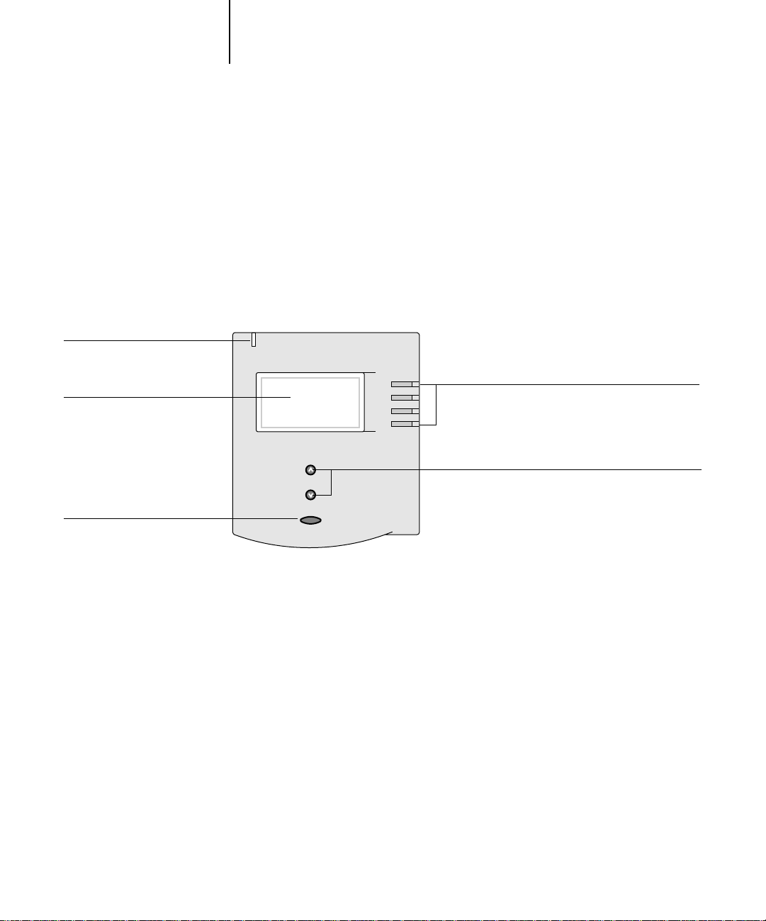
1-1 Introduction to the DocuColor 40 CP Control Panel
1
Chapter 1: Using the Control P anel
Activity light
Display window
Menu button
You can use the DocuColor 40 CP Control Panel to view status information, print
special pages, and set up printing.
Introduction to the DocuColor 40 CP Control Panel
The Control Panel, shown belo w on the front of the D ocuColor 40 CP, comprises the
following parts:
Line selection buttons
Up and down buttons
Activity light
The activity light indicates the current DocuColor 40 CP activity. If the light is:
Solid red An error has occurred causing the DocuColor 40 CP to be
disabled.
Flashing red There is an error causing printing to be disabled, but the
DocuColor 40 CP is capable of processing.
Solid green The DocuColor 40 CP is idle.
Flashing green The DocuColor 40 CP is processing or printing a job, or
communicating with a remote computer.
No light The DocuColor 40 CP is off or starting up.
Page 18

1-2 Using the Control Panel
1
Buttons
Line selection
buttons
Up and down
buttons
Menu button Press this button to view other screens. Under normal
There are four line selection buttons on the right side of the
Control Panel. Use these buttons to select the command
displayed on the corresponding line of the display window.
When a button is active, a special character (>) appears in the
display window next to the button.
Use these buttons to scroll to different screens in multi-
screen lists, to select Setup options from a list of available
options, and to scroll alphanumeric characters.
operation, the Control Panel displays the Info, RIP, or Print
Status screen with information about the status of the
DocuColor 40 CP. If you press the Menu button, the
Functions menu is displayed and you can perform additional
operations (see page 1-5). If a job is processing or printing,
press the Menu button to cycle among the active screens.
Page 19
1-3 Introduction to the DocuColor 40 CP Control Panel
1
Display window
The display window provides information about the status of the DocuColor 40 CP,
displays menu information, and enables you to view and edit information in the Setup
menus.
The last line of the display window displays text that tells you what screen you are
looking at and highlights one of the icons to indicate what the DocuColor 40 CP is
doing. Only the icons for the screens that are currently available appear. The menu
button cycles among the active screens.
The screens are:
Alert Status If there is a problem with processing a job or printing functions, an error message
appears on the Control Panel. F or information on error messages, see Appendix A,
“Troubleshooting.”
Print Status When the DocuColor 40 CP is printing a job, the Print Status screen appears.
This screen displays the following:
Cancel Job
printing.
User name
Pages/Total
number of copies of the job requested.
RIP Status When the DocuColor 40 CP is processing a job, the RIP Status screen appears.
This screen displays the following:
Cancel Job
processing. The DocuColor 40 CP cancels the job before printing begins.
Document name
User name
Kilobytes
OTE
N
1000KB; for example, 10MB is displayed as 10000KB.
—Press the top line selection button to cancel the job currently
—The name of the user who sent the job currently processing.
—The number of copies of the current job printed and the total
—Press the top line selection button to cancel the job currently
—The name of the document currently processing.
—The name of the user who sent the job currently processing.
—The size (in kilobytes) of the job processed so far.
:
This number is always displayed in kilobytes, even if the amount goes over
Page 20
1-4 Using the Control Panel
1
Info Status When the DocuColor 40 CP is not processing or printing a job, it displays
information about the current server and software. It displays the following
information:
Server Name
Status
status can be: Idle, Initializing, Busy, Processing, or Printing.
Megabytes
disk, for example, 756MB.
Version
Functions You can press the Menu button to display the Functions menu. Use the up and
down buttons to scroll through the list. Press the line selection button to the right
of a command to select that command. See page 1-5 for more information.
Network The network icon appears at the bottom left of any of the other screens when a
job is being sent to the DocuColor 40 CP, either over the network or through the
parallel port. The network icon also appears, together with a flashing green
activity light, when a remote utility is running.
—The DocuColor 40 CP name.
—The current status of the DocuColor 40 CP. The DocuColor 40 CP
—The space (in megabytes) available on the DocuColor 40 CP hard
—The system software version running on the DocuColor 40 CP.
Page 21

Print Pages
1-5 Introduction to the DocuColor 40 CP Control Panel
1
Functions menu
You can choose the following commands from this menu:
Print special pages from the DocuColor 40 CP. You can print the following pages
from the submenu that appears:
Suspend Printing
Resume Printing
Reboot Server
Test Page
properly connected to the copier, and provides color and grayscale samples to
troubleshoot problems with the copier or the DocuColor 40 CP. The following
settings are among those listed on the Test Page: Server Name, Printer Model,
color settings, calibration information, date and time the Test Page was printed.
Configuration
device configuration. This page lists general information about the hardware and
software configuration of the DocuColor 40 CP, the current options for all Setup
settings, information about the current calibration, and the Ethernet and Token
Ring addresses of the DocuColor 40 CP.
Job Log
Log and on printing it in other forms, see “Using the Job Log” on page 3-25.
Control Panel Map—
screens you can access from the Control P anel. For information about using these
screens to set up the DocuColor 40 CP, see the
Color Charts
from the DocuColor 40 CP.
Font List
Suspend communication between the DocuColor 40 CP and the copier. You
suspend printing if you want to interrupt the current DocuColor 40 CP job so
that you can use the copier to make copies. Jobs continue to process on the
DocuColor 40 CP. After you make the copies, select
printing jobs from the DocuColor 40 CP.
Resume communication between the copier and the DocuColor 40 CP after you
have finished making copies.
Shut down all DocuColor 40 CP activity in the correct manner and then restart.
You should use this option instead of the power switch on the back of the
DocuColor 40 CP.
—A Test Page enables you to confirm that the DocuColor 40 CP is
—Prints the Configuration page, which gives the current server and
—Prints a log of the last 55 jobs. For information on the fields in the Job
Prints the Control Panel Map, which is an overview of the
Configuration Guide
—Prints samples of the RGB, CMY, and PANT ONE colors av ailable
—Prints a list of all fonts currently on the DocuColor 40 CP hard disk.
Resume Printing
.
must
to continue
Page 22
1-6 Using the Control Panel
1
Starting and shutting down the DocuColor 40 CP
Generally, you can leave the DocuColor 40 CP running all the time. This section
describes how to shut down and restart the DocuColor 40 CP when necessary.
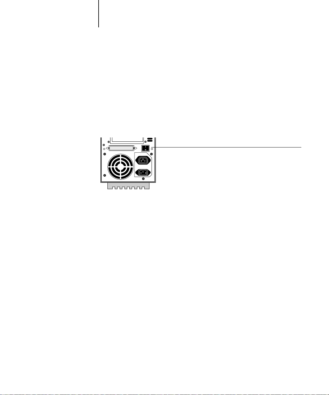
Starting the DocuColor 40 CP
To start the DocuColor 40 CP, move the power switch on the back of the
DocuColor 40 CP to the On position. If the copier is also powered off, power it on
before powering on the DocuColor 40 CP.
Power switch
Diagnostic messages appear on the DocuColor 40 CP Control Panel. If any
diagnostics fail, more information and instructions appear. Contact your service
representative if the DocuColor 40 CP encounters problems while running the
diagnostics.
When the diagnostics are finished, the following message is displayed:
For software update or setup, press any key.
If you want to change Setup option settings, press any button; if you do not press a
button, the DocuColor 40 CP continues starting up and displays the message
when it is ready to receive data.
N
:
If an Administrator password has been set, you are required to enter it to access
OTE
Setup.
If you press a button, the following options appear.
Idle
Page 23

1-7 Starting and shutting down the DocuColor 40 CP
1
For information about the Setup menus and options, see the Configuration Guide.
Choose: To do this:
Exit Setup
Server Setup
Network Setup
Printer Setup
PS Setup
Color Setup
Job Log Setup
Calibration
Change Password
Clear Server
Exit the Setup menus; the DocuColor 40 CP reboots.
Enter the Server Setup menus.
Enter the Network Setup menus.
Enter the Printer Setup menus.
Enter the PostScript Setup menu.
Enter the Color Setup menu.
Enter the Job Log Setup menu.
Calibrate the DocuColor 40 CP using AutoCal. For more
information, see “Calibrating with AutoCal from the Control
Panel” on page 4-6 and the Configuration Guide.
Change the Administrator password.
Clear all jobs in all server queues and the Job Log. Check
with your administrator or operator before choosing
Clear Server.
Restarting the DocuColor 40 CP
You should use the procedure described below to restart the DocuColor 40 CP rather
than using the power switch on the back of the DocuColor 40 CP.
TO RESTART THE DOCUCOLOR 40 CP:
1. Make sure that the DocuColor 40 CP is not receiving, processing, or printing a job.
Make sure that the status message on the Control Panel is Idle.
NOTE: If a job from the Print queue is processing, it will continue processing and print
after the DocuColor 40 CP is restarted; if a job sent to the Direct connection is
processing, it will not finish processing or printing.
2. Press the Menu button to display the Functions menu.
3. Use the down button to scroll to the last screen and choose Reboot Server.
Page 24

1-8 Using the Control Panel
1
Shutting down the DocuColor 40 CP
You may need to shut down the DocuColor 40 CP for service. When you do so, fonts
that have been downloaded to the hard disk drive are not deleted. Print jobs in the
Hold and Printed queues and jobs that have been processed but not printed are not
deleted and are available for printing when you restart the DocuColor 40 CP.
TO SHUT DOWN THE DOCUCOLOR 40 CP:
1. Make sure that the DocuColor 40 CP is not receiving, processing, or printing a job.
Make sure that the status message on the Control P anel is Idle. If a job has just finished
processing or printing, wait at least five seconds after the Control Panel status message
switches to Idle before proceeding to step 2.
NOTE: If a job from the Print queue is processing, it will continue processing and print
after the DocuColor 40 CP is restarted; if a job to the Direct connection is processing,
it will not finish processing or printing.
2. Power off the DocuColor 40 CP by moving the power switch on the back to the Off
position.
N
OTE: After powering off the DocuColor 40 CP, make sure to also power off the
copier. Leaving the copier po w ered on while the DocuColor 40 CP is powered off can
lead to excessive drain on the DocuColor 40 CP motherboard battery.
Page 25
2-1 About WebTools
2
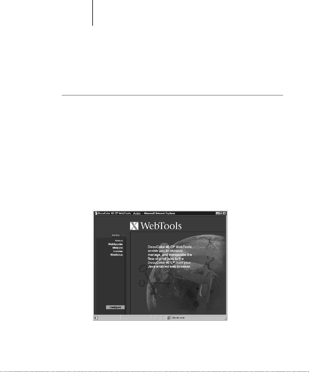
Chapter 2:
Overview o f
DocuColor 40 CP
W ebTools
This chapter introduces the DocuColor 40 CP WebTools: Status, WebSpooler,
WebLink, Installer, and WebSetup. It explains how to access these tools and describes
their functions. For more information on WebSetup and Installer WebTools, you are
referred to other manuals in the documentation set.
About WebTools
WebTools reside on the DocuColor 40 CP but can be accessed over the network from
Windows 95, Windows NT 4.0, and Mac OS client computers. The
DocuColor 40 CP has a home page that lets remote users view server functions and
manipulate jobs. For specific information on the browsers supported with WebTools,
see Getting Started.
The following DocuColor 40 CP WebTools can be accessed from the
DocuColor 40 CP WebTools home page.
WebTool: Summary: For more information:
Status Shows you the jobs currently processing
and printing.
W ebSpooler Allows you to view , manipulate, reorder ,
reprint, and delete jobs currently
spooling, processing, or printing on the
DocuColor 40 CP. Also allows you to
view, print, export, and delete the Job
Log. Most of these functions require an
Administrator or Operator password, if
one has been set.
See page 2-4
See “WebSpooler” on page 3-1
WebLink Provides a link to another web page,
provided you have a valid Internet
connection. The WebLink destination
can be changed; this function requires
the Administrator password, if one has
been set.
See page 2-5 and the
Configuration Guide
Page 26
2-2 Overview of DocuColor 40 CP WebTools
2
WebTool: Summary: For more information:
Installer Allows you to download
DocuColor 40 CP printer file installers
directly from the server.
WebSetup Allows you to modify the
DocuColor 40 CP configuration
(Setup) remotely . This function r equires
the Administrator password, if one has
been set.
Access privileges
The DocuColor 40 CP system allows the site administrator to choose and implement
a level of access and control appropriate for your particular site. The levels of access
allowed to remote users depend on whether the administrator has enabled use of the
W ebTools, and whether a password is required to use certain features of the W ebTools.
The three possible levels of access to WebTools are Administrator, Operator, and
Guest. To enable maximum password protection, Administrator and Operator
passwords must be specified in Setup (see the Configuration Guide).
NOTE: An Operator password can be set only by using WebSetup.
When both an Administrator password and an Operator password have been specified,
the access levels are as follows:
See Getting Started
See the Configuration Guide
Access level: Privileges and password requirements:
Administrator Has full access to all WebTools and DocuColor 40 CP Control
Panel functions; Administrator password required.
Operator Has access to all functions of WebTools except WebSetup and
clearing the Job Log from WebSpooler; Operator password
required.
Guest Can view job status, but cannot make changes to jobs or Setup,
and cannot view the Job Log; no password required.
Page 27
2-3 About WebTools
2
If you have been given the Operator password, you can manage job flow and override
print settings of your jobs with WebSpooler. If not, you can still log in as Guest and
use these tools, and the Status WebTool, to track the status of your jobs. Check with
your site administrator for information on your access privileges.
TO ACCESS WEBTOOLS:
1. Start up your Internet browser application.
See Getting Started for information about supported platforms and browsers.
2. Enter the IP address or the DNS name of the DocuColor 40 CP.
Check with the operator or administrator for this information.
3. If the Log In dialog box appears, select a login lev el, enter the passw or d, and click OK.
The Log In dialog box appears only if the administrator has set an Administrator or
Operator password (or both).
4. When the DocuColor 40 CP WebTools home page appears, click to select one of the
WebTools.
Move the cursor over the buttons to display information about the selections.
Page 28
NOTE: The Configure button appears only if you logged in as Administrator. With
Administrator privileges, you can click this button and specify which of the WebTools
are available to other users.
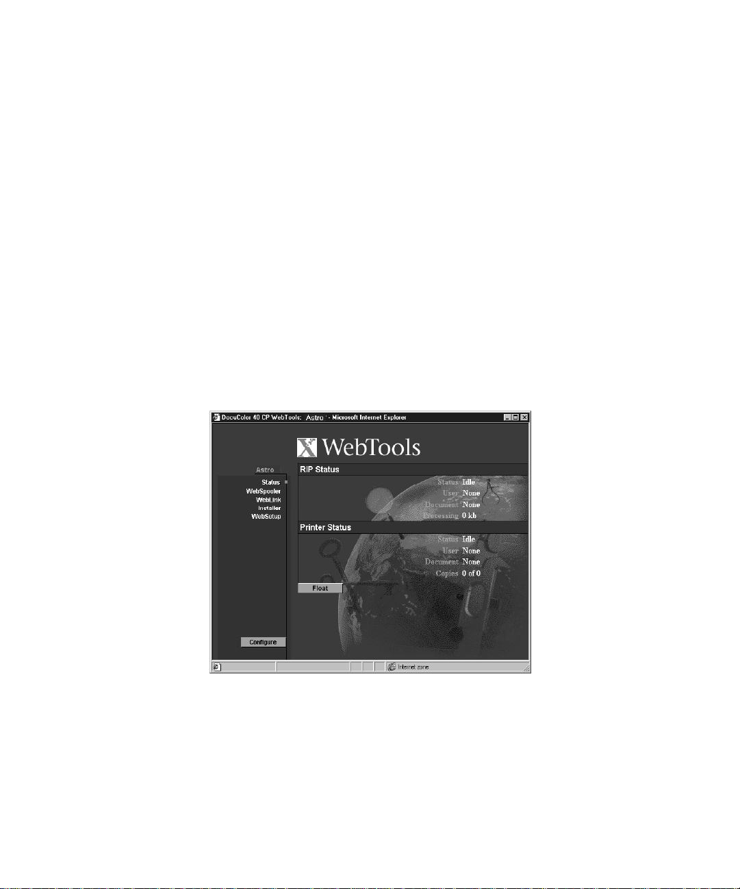
Checking DocuColor 40 CP status with the Status WebTool
You can use the Status WebTool to see what jobs are currently processing and printing.
The Status WebTool does not require any special access privileges. If the administrator
has enabled Web Services in Setup and has provided you with the IP address of the
DocuColor 40 CP, you can use the Status W ebTool to monitor the status of print jobs
as they are rasterized and printed.
To access the Status WebTool, point y our bro wser to the D ocuColor 40 CP WebTools
home page and click Status. The current RIP Status and Printer Status appear in the
window.
To open a new browser window for the Status display, click Float. You can then close
other browser windows and leave the Status window open to continue checking the
status of the DocuColor 40 CP. As long as you keep the Status window open, it is
dynamically updated.
To obtain more information about the status of jobs, use WebSpooler.
Page 29
2-5 About WebTools
2
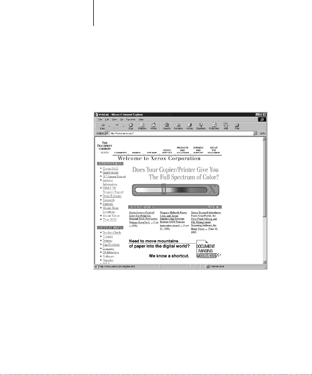
Accessing information with the WebLink WebTool
The WebLink button on the DocuColor 40 CP WebTools home page provides a link
to another web page or to multiple web pages, provided you have a valid Internet
connection. The WebLink destination is initially set to www.xerox.com. The
administrator at your site can set the WebLink destination. Check the WebLink sites
for any information available there.
Page 30

Page 31

3-1 WebTools for job tracking and management
3
Chapter 3: Tracking and Managing Print Jobs
TO LAUNCH WEBSPOOLER:
This chapter describes the functions of the DocuColor 40 CP WebTools that let you
track and manage jobs sent to the DocuColor 40 CP.
WebTools for job tracking and management
If your site administrator has enabled Web Services on the DocuColor 40 CP, you can
access WebTools from Windows 95, Windows NT 4.0, and Mac OS computers with
an Internet browser. The WebTools that provide job tracking capabilities are
WebSpooler and the Status WebTool. WebSpooler also provides job management
capabilities, provided you have the necessary access privileges (see page 2-2). For
specific information on the browsers supported with WebTools, see Getting Started.
WebSpooler
WebSpooler provides a window on DocuColor 40 CP and copier functions, and an
interface from which you can control those functions.
1. Launch your internet browser and enter the IP address or DNS name of the server you
want to connect to.
2. If a password has been set, the Log In window appears.
To log in as Administrator, enter the Administrator password and click OK.
To log in as Operator, enter the Operator password and click OK.
To log in as Guest, click OK, without entering any password.
3. From the DocuColor 40 CP WebTools home page window, click WebSpooler.
For instructions on how to access the DocuColor 40 CP WebTools home page
window, see page 2-3.
Page 32

3-2 Tracking and Managing Print Jobs
3
The WebSpooler window appears in a new browser window.
Job management features
Unless passwords have been defined in D ocuColor 40 CP Setup, you can log in to the
WebTools home page without entering a password, and you are given full privileges to
WebSpooler which include:
• A view of current printing jobs and jobs stored on the DocuColor 40 CP
• Control of printing jobs and a view of the Job Log
• Ability to clear the Job Log
Page 33

3-3 Tracking and Managing Print Jobs
3
After the Administrator has performed Setup and specified passwords, user options
depend on your login level. If you log in to the WebTools home page as Guest, you
have the first option only. If you log in as Operator, you have the first two options. If
you log in as Administrator, you have all three options. For information about Setup
and specifying passwords, see the Configuration Guide.
You can use WebSpooler to perform the following functions from your workstation:
• Override current job option settings
• Delete jobs
• Duplicate or rename jobs
• RIP a job and hold the raster data
• Hold jobs in the spooled area or the RIPped area
• Remove raster data from RIPped files
• Change the priority of jobs
• Edit and merge raster data jobs (DocBuilder)
• Display, print, export, or delete the Job Log
Most of these functions require Administrator or Operator privileges. However, even
without a password, you can log in to the WebTools home page as Guest with viewonly privileges in WebSpooler.
Job List window
Your first view of WebSpooler is the Job List window, which is divided into three areas
by Spool, RIP, and Print status bars. The Job List window is surrounded by a frame
that includes slider buttons and menus. System information indicators at the bottom
of the window show the current availability of hard disk space and RAM on the
currently selected DocuColor 40 CP server.
When the DocuColor 40 CP is receiving and processing print jobs, the Job List
window is a dynamic display, filled with the names of jobs and their characteristics.
Status bars animate in real time as new jobs are processed and printed, and jobs move
to different display areas.
Page 34

3
S
Menu bar
pool status bar
Spooled jobs
RIP status bar
Rasterized (RIPped) jobs
Print status bar
Printed jobs
3-4 Tracking and Managing Print Jobs
System information indicators
The Spool, RIP, and Print areas of the Job List window represent the stages of printing
a job. Jobs come in at the top level (Spool) and drop down to the Print level, unless
they are held along the way.
• Spooled jobs—Jobs listed in the area below the Spool status bar area are PostScript
files stored on the DocuColor 40 CP disk. These jobs were sent to either the Print
queue (white icons) or the Hold queue (yellow icons). These PostScript files are
saved on the server’s hard disk. PostScript files can come in packets from the
network, or from another place on the server hard disk. Jobs are added to a queue in
the order in which they arrive, and they generally move to another queue in the same
order unless an operator has intervened to change the order.
• RIPped jobs—Jobs listed in the area below the RIP status bar are ready to print.
They have already been rasterized (RIPped, or processed for printing) and are
waiting, in order , for access to the printer. Rasterized jobs can also be held; held jobs
are shown with a yellow icon. During RIPping, PostScript commands are
Page 35

3-5 Tracking and Managing Print Jobs
3
interpreted in the DocuColor 40 CP to allow the DocuColor 40 to print the file the
way its originator intended. The result of this interpretation is a raster file associated
with the original PostScript file. In this raster file (raster image), color data is
associated with each dot that can be rendered by the print engine. The color data
tells the print engine whether or not to apply cyan, magenta, yellow, or black toner
to each position on the page.
• Printed jobs—Jobs listed in the area below the Print status bar have already been
printed. Printed jobs can be stored on the DocuColor 40 CP disk. The number of
jobs that can be stored (from 1 to 99) is defined in Setup. While the PostScript file is
usually saved to disk, raster images are held in RAM during and after each print job.
However, you can request that the DocuColor 40 CP save the raster image to disk
along with the PostScript file. Saving the raster image to disk offers some
advantages—raster files are already processed so they print quickly, and each part of
the raster file is still identified with a page in the original document, which means
that individual pages of a saved raster file can be accessed.
Errors—Jobs with an error are shown in red. To display the error, double-click the
•
job line.
If you are logged in with Administrator or Operator privileges, you can interact with a
job in the window by selecting it and choosing a command from the Job menu, or by
double clicking it and setting print option overrides. (However, if passwords have been
set and you are logged in with Guest privileges, you can only view jobs; you cannot
interact with them.)
The job icons displayed in the WebSpooler window are explained on page 3-9.
NOTE: If your job does not appear anywhere in the WebSpooler window, it may have
already been printed; if so, it will appear in the Job Log. To view the Job Log, choose
Show Job Log from the Window menu. (For more information on the Job Log, see
page 3-25.)
Menu bar
The menu bar has five menus. When an action is not available in the current context,
the command is dimmed.
Page 36

3-6 Tracking and Managing Print Jobs
3
Menu: Choose this: To do this:
File Print Job Log Print the Job Log
Delete Job Log Delete the Job Log
Export Job Log Export the Job Log
Exit Exit W ebSpooler
Job
(For more
information on
these commands,
see page 3-12)
Page
(DocBuilder
commands for
Thumbnail A)
Delete Job(s) Delete one or more selected jobs
Duplicate Job(s) Duplicate one or more selected PostScript data jobs in the Spool or Print areas
Rename Rename a selected job
Hold Hold the selected job(s); see page 3-7
RIP and Hold RIP and then hold the selected job(s); see page 3-7
Print Print the selected job(s); see page 3-11
Print and Hold Print the selected job(s) and then hold it in the RIP area; see page 3-7
Process Next Give top priority to this job
Remove Raster Remove the raster information from the selected job(s); see page 3-14
Override Print
Settings
Thumbnail A Open a selected held raster data job in the Thumbnail A window where you
Thumbnail B Open a selected raster data job (not necessarily a held job) in the Thumbnail B
Delete Delete the selected page(s)
Duplicate Duplicate the selected page(s)
Preview View a full-screen preview of the selected page; see page 3-24
View and edit print settings for the selected job(s); see page 3-14
can view a full-screen preview of the job, edit the job, or merge it with raster
data from other jobs; see page 3-16
window for viewing or for copying pages into a job in the Thumbnail A
window; see page 3-18
Undo Undo previous Page menu commands (multiple undos available)
Page 37

3-7 Tracking and Managing Print Jobs
3
Menu: Choose this: To do this:
Window Show Job List Show the Job List window
Show Job Log Show the Job Log window
Help About View the WebSpooler information screen
Status bars
Jobs actively involved in the three processes (spooling, rasterizing, and printing) are
listed in the status bars that span the Job List window.
Status bars show the filename and user name for the active process, and an indication
of its progress. Each status bar heads the list of jobs that have completed the process.
Thus, beneath the Spool status bar, you see a list of spooled files; beneath the RIP
status bar, you see a list of rasterized (RIPped) files. Beneath the Print status bar, you
see a list of jobs that have already been printed.
NOTE: In the Spool status bar, the filename and user information always appear as
“Unknown” (as shown below). This information is not available until the job has
finished spooling to the DocuColor 40 CP disk.
Active jobs and Held jobs
You can hold a job at any stage of the process we have described, as illustrated below. I n
the figure, boxes indicate types of job icons you would see in the Job List window.
Page 38

3-8 Tracking and Managing Print Jobs
3
Spool
Spooled and held
Spooled for printing
RIP
RIPped and held
Print*
RIPped for printing
Print
Print and hold
Printed
*A copy of the held job is printed; the held job remains in the RIP area.
Jobs that are held are shown with a yellow icon, just beneath the Spool or RIP status
bar. Jobs that are held must be activated with a command in order to print.
Active jobs are shown with white icons; new jobs are added above older jobs.
PostScript and
raster data
Deleted
Page 39

3-9 Tracking and Managing Print Jobs
3
Job icons
There are three types of icons that are used for both active jobs and jobs on hold.
Icon:
Printer icons
Raster icon
Active jobs:
(white icons and rows)
PostScript or raster data
headed for printing (top) or
after printing (bottom)
PostScript and raster data
after printing, ready for fast
reprint
PostScript data headed for
and Hold
printing (
PostScript data already rasterized
and held
Jobs on Hold:
(yellow icons and rows)
or job on Hold after
Hold)
Spool area
The job icons in the Spool area are described below:
Spool area icon: What it indicates: How long you see the job:
1
Yellow printer icon
Yellow job row
2
White printer icon
White job row
PostScript data from a user on
the network; no destination is
defined
PostScript data headed for
Print
Until a destination is chosen
Until the RIP is free
Print
3
Yellow raster icon
White job row
4
Yellow printer icon
White job row
PostScript data headed for
RIP and Hold
PostScript data headed for
Print and Hold
Page 40

3-10 Tracking and Managing Print Jobs
3
The Spool area is both the receiving area for jobs from users on the network (Hold
queue) and the waiting area for jobs that will be RIPped (jobs in the Spool queue).
Hold queue jobs When printing requires an operator (because the Print queue and
Direct connection are disabled), the operator must assign a destination to all jobs
received from users on the network (icon 1 in the table above). Once assigned, jobs
(icons 2, 3, and 4) move down the Spool queue for processing. All jobs printed to the
Hold queue require routing by an operator.
Print queue jobs When printing does not require an operator, network jobs sent to
the Print queue appear in the Spool area where they are shown with a white printer
icon (icon 2). When they reach the head of the queue, they are RIPped and printed
without operator intervention.
Direct connection jobs Jobs printed to the D irect connection are not displayed in the
job lists. They are displayed briefly in the status bars (where they cannot be selected)
and are included in the Job Log.
RIP area
The job icons in the RIP area are described below:
RIP area icon: What it indicates: How long you see the job:
1
Yellow raster icon
Yellow job row
2
White printer icon
White job row
After a job is rasterized, it goes into the RIP area. The RIP area holds only raster data
(i.e., jobs that have been rasterized). Jobs in the RIP area are either waiting for the
copier to be free (Print queue jobs, icon 2 in the above table), or they are being held.
Raster data, no destination
defined; may have been
printed before and held
Raster data headed for
in its turn; no hold defined
Print
Until it is deleted or stripped
of its raster data and sent to
the Spool area
Until copier is free to print
the job
Page 41

3-11 Tracking and Managing Print Jobs
3
Held jobs in the RIP area have already been rasterized (RIP and Hold) or they have
been printed and their raster data has been routed back to the RIP area (Print and
Hold), where they are shown in yellow rows (icon 1).
NOTE: Raster jobs in the RIP area that are waiting to print (icon 2 in the table above)
cannot be manipulated by job commands.
Jobs held in the RIP area remain there until the operator deletes them. Printing these
jobs does not remove them from the RIP area. Instead, a copy of the job is cr eated and
printed.
NOTE: For all rasterized jobs, the print option settings, in addition to the current
calibration state of the DocuColor 40 CP, remain with the saved raster data each time
the job is reprinted. To print the job with new print option settings and with new
calibration data, you must remove the raster data and reRIP the job.
Print area
The job icons in the Print area are described below:
Print area icon: What it indicates: How long you see the job:
1
White printer icon
White job row
2
White raster icon
White job row
The Print area, also referred to as the Printed queue, contains jobs that have already
been printed. These jobs were assigned the Print destination (white printer icon in the
Spool or RIP areas) without any Hold instructions; therefore, they all hav e white icons
and rows.
NOTE: A job row that appears in light red indicates that a PostScript error occurred
while printing the job. To see the error, double-click anywhere in the row.
PostScript data only—raster
data has been deleted
Raster and PostScript data
If RAM is needed to RIP an
active job, the raster data is
deleted and the job gets the
PS icon (icon 1, above)
Until the job limit is reached
Until the job is reprinted or
the job limit is reached
Page 42

3-12 Tracking and Managing Print Jobs
3
Newly printed jobs are added to the Printed queue, and ar e shown at the top of the list.
Jobs are saved in the Printed queue until the job limit is reached. When the first job
over the limit is printed, the oldest job is deleted from the disk. The default job limit is
10 jobs. The value for Jobs Saved in Printed Queue can be changed in Setup by the
administrator.
NOTE: If you reprint a job in the Printed queue, the job returns to its original position
in the Printed queue after it is printed.
While it is printing, a job consists of PostScript and raster data. The raster data in
RAM is not cleared until memory is needed to rasterize the next job. As long as the
raster data is intact, the job can be reprinted from the Printed queue. Printed jobs that
still have their raster data are represented by a white raster icon in the Printed queue
(icon 2 in the previous table); jobs with only PostScript data r emaining are r epresented
by a white PS icon (icon 1). If the job was printed from a held raster job (in the RIP
area), the raster data in the RIP area remains and can be used to reprint the job after
the raster data has been cleared from the Printed queue.
Job commands
Using the commands in the Job menu, you can alter the destinations, priorities and
other characteristics of jobs that appear in the WebSpooler window.
Job commands are used to assign a selected job to a new destination or process. These
commands are available from the Job menu (see page 3-5). The job commands
available at a given time depend on the context; unavailable commands are dimmed.
Page 43

3-13 Tracking and Managing Print Jobs
3
The job commands available for selected jobs in the Job List window are listed in the
following table. The table also describes the effect of each command on raster data
associated with the affected job(s).
Choose this: To do this: Raster data is:
Delete Job(s) Delete the job(s) Deleted
Duplicate Job(s) Duplicate one or more selected PostScript data
jobs in the Spool or Print areas. You can use the
duplicate job(s) for different print options or a
different destination. (The Duplicate command
actually creates a reference to the original job,
with the same name)
Rename Rename the job (PostScript file with or without
raster)
Hold Hold the job in the current place (except for a job
in the Print area, which is moved to the Spool or
RIP area, depending on whether it still has raster
data associated with it)
RIP and Hold RIP the job and hold it in the RIP area Held in RIP area indefinitely
Print Print the job in its turn (RIP it first if it does not
have raster data)
After printing, keep the printed job in the Print
area until the job limit is reached.
Print and Hold
(Like the user print
option Save Fast
Reprint)
Print the job in its turn (RIP it first if it does not
have raster data)
After printing, hold the PostScript data and the
raster in the RIP area
N
OTE: The Duplicate command is not
available for raster jobs
Unaffected, but associated with the new name
OTE: If the renamed job is printed, the J ob Log
N
reflects the job’s original name.
Held in RIP area, if included with job
Temporarily held in RAM after printing until
memory is needed for another job
(If the job was printed from a held job in the RIP
area, the raster data in the RIP area is kept
indefinitely)
Held in RIP area indefinitely (saved to disk)
Process Next Give top priority to this job
RIP (and then print) it as soon as the processor is
free, before other waiting jobs
Option is dimmed if there are no other waiting
jobs
N
OTE: This command is available only for jobs in
the Spool area that are not currently held.
Page 44

3-14 Tracking and Managing Print Jobs
3
Choose this: To do this: Raster data is:
Remove Raster Remove the raster data from a job that has raster
data (indicated by a raster icon); leave the
PostScript data unaffected
Override Print
Settings
Thumbnail A Open the selected held raster data job in the
Thumbnail B Open the selected raster data job (not necessarily
View and override print settings for a selected job
or a group of selected jobs
Thumbnail A window where you can view a full-
screen preview of the job, edit the job, or merge it
with raster data from other jobs
a held job) in the Thumbnail B window for
viewing or for merging into a job in the
Thumbnail A window
Overriding print settings
When logged in with Operator or Administrator privileges, you can use the Override
Print Settings command to check and override the print option settings (pr operties) of
all jobs.
You can use this command for several purposes:
• To override a setting based on printed output or other print device conditions
Deleted
N
OTE: If you remove raster from a job in the RIP
area, the job is sent to the Spool area.
Possibly deleted and regenerated, depending on
whether you change any settings that require reRIPping
May be changed if job is edited
Unchanged
• To change settings for a duplicate of the original job
• To print a single copy of a job before printing the number of copies required by the
user
To change the job options of a job, double-click the job line or select the job and
choose Override Print Settings from the Job menu. If necessary, scroll down to see all
the various job options.
Page 45

3
Indicates reRIPping is required
3-15 Tracking and Managing Print Jobs
PDF Settings dialog box for PDF files
Override Print Settings dialog box for
PostScript files
The options you set here are the same ones you set from the P rint dialog box when you
print from an application. For information about print options, see the P rinting G uide.
For some options, changing the setting requires that the job be reRIPped; these
options show an icon to the left of the option name.
For PDF files, you can override only the number of copies and page range from the
Properties dialog box.
If you want to retain a copy of the job with its original settings, duplicate the job and
rename the duplicate before you change any settings (see “Job commands” on
page 3-12).
The Override Print Settings dialog box displays all the job settings encoded by the
PostScript printer driver that can be decoded by the DocuColor 40 CP. If you (as
operator) have not changed anything, these are the settings a user entered before
sending the job.
Page 46

3-16 Tracking and Managing Print Jobs
3
NOTE: Some print options that are available in the printer driver are not displayed in
the Override Print Settings dialog box.
For information on print option settings, see the Printing Guide.
Thumbnails and full-screen previews (DocBuilder)
The WebSpooler includes a powerful DocBuilder tool that allows you to preview and
edit raster data. (For information on how to identify a raster data job, see page 3-9.)
DocBuilder consists of two thumbnail windows and several page-manipulation
commands (listed in the Page menu).
The DocBuilder tool can be used in the following ways:
• In the Thumbnail A window, you can see thumbnails of the currently RIPping job,
as it is processed, or of any raster data job.
• From the Thumbnail A window you can open a full-screen preview of a raster file.
• Using the Thumbnail A and Thumbnail B windows together, you can merge raster
data from more than one file, even if the files were printed from different
applications on different computer platforms.
DocBuilder’s merge features eliminate the limitations of particular software
applications. You can merge raster pages of documents of different types, and even
different computer operating systems. You can merge color pages from graphics
programs with text pages from a word processor.
Previewing print jobs
You can use the Thumbnail A window to preview pages of the currently RIPping job.
You can also use Thumbnail A, as well as Thumbnail B, to preview any raster data job
in the RIP or Print areas.
The thumbnail windows also allow you to open an editable thumbnail view of a held
raster job in the RIP area and perform electronic collation or document merging. This
feature, called DocBuilder, is described on page 3-18.
To see the progress of jobs as they are RIPped, you can leave the Thumbnail A window
open in RIP preview mode.
Page 47

3-17 Tracking and Managing Print Jobs
3
TO VIEW THUMBNAILS OF THE CURRENTLY RIPPING FILE:
1. Click the Thumbnail A tab at the right of the Job List window to open the slider.
2. Click the RIP preview icon at the left side of the window.
In this mode, Thumbnail A displays each page of the currently processing job after it
has been RIPped.
Click to display the currently
rasterizing job
TO VIEW THUMBNAILS OF ANY RASTER DATA FILE:
Click to close the
thumbnail window
3. Choose a PS file in the Spool or Print area and select RIP and Hold, Print, or
Print and Hold.
As pages are RIPped, they are displayed in the Thumbnail A window.
4. When you have finished viewing, click the Thumbnail A tab to close the thumbnail
window.
1. Select any raster data job in the RIP or Print area.
2. Choose Thumbnail A or Thumbnail B from the Job menu.
If you choose Thumbnail A, make sure the raster data preview icon (at the left side of
the window) is selected.
NOTE: Wait until all pages have been displayed before opening another raster file with
Thumbnail A. If the job contains many pages, it may take some time for the entire job
to be displayed.
Page 48

3-18 Tracking and Managing Print Jobs
3
Raster data preview icon
Click to close the
thumbnail window
3. When you have finished viewing, click the Thumbnail A or Thumbnail B tab to close
the thumbnail window.
Editing and merging files with DocBuilder
When you select a raster data job and choose the Thumbnail A or Thumbnail B
command from the Job menu, the corresponding Thumbnail slider opens
automatically , displaying thumbnails of the editable file. To close the Thumbnail slider,
click anywhere in the tab along the right edge of the Thumbnail window. When the
Thumbnail window is open, the arrows in the tab point to the right, indicating that
clicking the tab retracts the slider.
With the Thumbnail A window you can see thumbnail views of any raster data job—
that is, any file that is currently RIPping, or any file that has been RIPped and held to
disk. You can also use the Thumbnail A window to edit a raster file—you can change
the sequence of pages, delete pages, duplicate pages, and copy pages from other raster
files into the Thumbnail A window. You can save the edited raster file as a new
printable document.
The Thumbnail B window can also display thumbnails of a raster job, and the
document displayed in Thumbnail B can be used as a source for editing the document
shown in Thumbnail A.
NOTE: Be careful not to delete a Thumbnail job entirely without first saving a copy.
Page 49

3
Click to expand or retract
the Thumbnail B window
3-19 Tracking and Managing Print Jobs
Thumbnail B (source)
Click to expand or retract
the Thumbnail A window
Thumbnail A (target)
Click here to close the Thumbnail B
window
Click here to close the Thumbnail A
window
You can merge documents by dragging (copying) one or more entire pages from
Thumbnail B to Thumbnail A. This creates a new document in the Thumbnail A
window. If you select one or more pages in the Thumbnail A window, the commands
in the Page menu give you additional editing possibilities. Multiple undos of Page
menu commands are possible.
You can merge pages from multiple documents into the Thumbnail A document by
opening documents one after another in the Thumbnail B window. Documents in the
Thumbnail B window are view-only, and while you can copy pages from Thumbnail B
to Thumbnail A, you cannot edit the Thumbnail B document. A merged document
that you create in Thumbnail A can be saved (with a different name) as a new raster
data file.
The ability to work with raster files gives you new opportunities to combine
documents from different sources into a single printer file. For example, you can
combine full color covers and chapter head pages created in a page layout application
with two-color text pages created in a document processing application. Or, you can
customize a slide presentation by inserting slides from a different presentation.
Page 50

3-20 Tracking and Managing Print Jobs
3
You can display two raster files at once: a source file and a target file. The target file is
displayed in the Thumbnail A window, the source in Thumbnail B. Both files must be
held raster jobs in the RIP area.
NOTE: You cannot create a new PostScript file in this process; you must print the
merged raster file, which has references to the original P ostScript files. Before editing or
merging files with DocBuilder, make sure the source files were RIPped using the print
option settings and the resident calibration you want for the final output. Raster files
edited with DocBuilder cannot be reRIPped.
TO VIEW AND EDIT RASTER DATA JOBS:
1. Select a raster data job and choose Thumbnail A from the Job menu.
The file must be a held raster job in the RIP area.
2. Select the Page menu to see the commands available for pages in Thumbnail A.
These commands can also be accessed from the buttons along the left side of the
Thumbnail A window (see illustration below).
To scroll through the pages in Thumbnail A, you can click in the empty area to the left
or right of the slider bar, or click on the arrows.
Click to open a full-screen
preview of the page
Click to duplicate a page
Click to delete a page
Delete deletes the currently selected page.
Duplicate duplicates the currently selected page.
Preview opens a full-screen preview of the currently selected page (see “Full-screen
previews” on page 3-24).
Page 51

3-21 Tracking and Managing Print Jobs
3
3. To move pages within Thumbnail A, left-click to select the page(s) and hold down the
Undo undoes the previous DocBuilder command—this command is available only from
the Page menu.
mouse button as you drag the selected page(s) to the new location.
Shift-click to select multiple, sequential pages; Ctrl-click to select multiple, nonsequential pages. Make sure to release the Shift or Ctrl key before moving the pages.
If you move the page(s) on top of existing page(s), the page(s) will be overwritten.
If the icon does not have an arrow, the page(s) will be replaced; if the icon has an arrow,
the page(s) will be inserted.
…
Replace single page Replace multiple pages
…
Move single page Move multiple pages
between two pages between two pages
…
Move single page Move multiple pages
before first page before first page
…
Move single page Move multiple pages
after last page after last page
4. When you are finished editing, click the Thumbnail A tab.
If you have edited the job, you are prompted to save the job (click Yes) and enter a new
name.
5. Enter a new name and click OK.
The new raster file is now in the RIP area, ready to print. If you saved the edited file
with a new name, the original source file remains held in the RIP area.
Page 52

3-22 Tracking and Managing Print Jobs
3
TO MERGE TWO RASTER DATA JOBS:
1. In the Thumbnail A window, display the document you wish to edit.
The file must be a held raster job in the RIP area.
2. Select another source document file (a held job with a raster icon) and choose
Thumbnail B from the Job menu.
The Thumbnail B tab opens a second thumbnail view which cannot be edited but can
be a source for pages added to the document in Thumbnail A.
NOTE: To merge documents, the page sizes of the source document and the target
document must be the same.
3. In the Thumbnail B window, left-click to select the page(s) and hold down the mouse
button as you drag the selected page(s) to the new location in Thumbnail A.
Shift-click to select multiple, sequential pages; Ctrl-click to select multiple, nonsequential pages. Make sure to release the Shift or Ctrl key before moving the pages.
To scroll through the pages in Thumbnail A and Thumbnail B, you can click in the
empty area to the left or right of the slider bar, or click on the arrows.
To replace page(s), drag Thumbnail B page(s) on top of page(s) in Thumbnail A; to
add page(s), drag the page(s) to a new position between pages, before the first page, or
after the last page in Thumbnail A (see the icons on page 3-21).
NOTE: To insert a Thumbnail B page directly after the last Thumbnail A page, drag the
Thumbnail B page so that it is just to the right of the last Thumbnail A page and
shows an arrow pointing to the right. If the Thumbnail B page is placed too far to the
right of the last Thumbnail A page, the Thumbnail B page will replace the last
Thumbnail A page.
Page 53

3
Thumbnail B
Page 2 copied from the
document in Thumbnail B
3-23 Tracking and Managing Print Jobs
Multiple undos are available; use the Undo command (from the Page menu) to undo
all the way back to your first edit. There is no Redo function.
NOTE: Make sure to save the merged job before deleting any of the source jobs you used
to create the merged job.
Thumbnail B pages moved into Thumbnail A adopt some specific attributes of the
Thumbnail A job, such as the document and user name. However, many color-related
print options that are set in the Thumbnail B page, such as CMYK Simulation and
Rendering Style, remain with the specific page. This could r esult in a merged job being
made up of pages with different attributes.
Generally, the print option settings specified for the Thumbnail A job that are adopted
by the pages copied from Thumbnail B do not require reRIPping to take effect. The
one exception is the setting specified for the Save Fast Reprint option, which requires
reRIPping if you want to change it.
The print option settings that remain with the pages copied from Thumbnail B into
Thumbnail A are generally those that do require reRIPing to take effect.
Page 54

3-24 Tracking and Managing Print Jobs
3
4. To close the Thumbnail view, click once on the same tab you used to open it
5. If you have edited Thumbnail A, you are prompted to save the job (click Yes) and
Attributes that do not require reRIPping can be changed for the newly merged job
without having to reRIP any original PostScript files. A ttributes that require r eRIPping
result in reRIPping of the original PostScript file(s) associated with Thumbnail A.
(Thumbnail A or Thumbnail B tab).
enter a new name. Enter a new name and click OK.
The new raster file is now in the RIP area, ready to print, together with the original
source and target files.
NOTE: If you print the edited raster file, it appears in the Job Log with the name of the
original job, not the new name you specified for the edited job.
Since you cannot create a new P ostScript file by merging two raster data jobs, you must
print the merged raster file, which has references to the original PostScript files. If a
merged job is reRIPped and printed, then only the pages of the original PostScript job
in Thumbnail A will be processed and printed.
NOTE: In cases where multiple users are connected to the DocuColor 40 CP via
WebSpooler and one user makes changes to a Thumbnail A job, not all users may see
the results of those changes. If you are unable to view changes in a job, or if selecting a
Thumbnail window results in a message indicating zero pages, then close and relaunch
W ebS pooler.
Full-screen previews
Double-clicking any page in the Thumbnail A window opens a full-screen preview of
the page. The full-screen preview is a view-only display, and it takes time to retrieve the
data. Once begun, the process cannot be canceled.
NOTE: If you have edited a raster job with DocBuilder, you must save the edited file
before you can view full-screen previews of all its pages.
Page 55

3-25 Tracking and Managing Print Jobs
3
Using the icons in the full-screen preview, you can display adjacent pages, rotate the
page, or close the preview.
Click to close the full-screen preview
Click in empty spaces or move
bar to scroll left or right
Click in empty spaces or move bar
to scroll up or down
Using the Job Log
From WebSpooler, you can view and print a log of all jobs printed by the
DocuColor 40 CP, including jobs downloaded with Downloader.
NOTE: If you are logged in with Administrator privileges, you can delete the Job Log
from WebSpooler (see page 3-27). The Job Log is not available if you are logged in
with Guest privileges.
Page 56

3-26 Tracking and Managing Print Jobs
3
TO DISPLAY, UPDATE, PRINT, DELETE, AND EXPORT THE JOB LOG:
1. Choose Show Job Log from the WebSpooler Window menu.
2. Click All or specify a date range.
3. Click OK.
The Job Log appears in a new browser window.
NOTE: The Delete button appears only if you are logged in with Administrator
privileges.
Update
Print
Delete
Export
Page 57

3-27 Tracking and Managing Print Jobs
3
4. To update the Job Log, click the Update button.
5. To print the Job Log, choose Print Job Log from the File menu or click the Print
The Job Log displays each job and the following information: status, document name,
user name, date, start time, end time, process time, file size, device, paper size, media,
number of originals, number of color pages, number of black-and-white pages, total
number of pages, Note1, and Note2.
The Status column provides the following information about jobs:
OK
ERROR
CANCEL
button.
The information displayed in the Job Log window prints to the current
DocuColor 40 CP. When you print the Job Log, totals are printed for all appropriate
columns.
The job was printed normally.
An error occurred during processing or printing.
The job was canceled before printing was completed.
6. If you are logged in with Administrator privileges , you can choose Delete Job Log fr om
the File menu or click the Delete button to clear the Job Log.
The system administrator can also print and clear the Job Log from the Control Panel.
7. To export the Job Log, click the Export button or choose Export Job Log from the File
menu.
The information displayed in the Job Log window is saved as a tab delimited file which
can be imported into a word processing or spreadsheet application for administration
purposes.
Page 58

Page 59

4-1 Introduction to color calibration
4
Chapter 4: Color Calibration
Calibrating the DocuColor 40 CP ensures consistent, reliable color output. You can
calibrate the DocuColor 40 CP in the following ways:
• Using AutoCal from the DocuColor 40 CP Control Panel—AutoCal allows you to
obtain measurements from the DocuColor 40 and apply a calibration using a
desktop scanner.
• Using Print Calibrator and a scanner or densitometer from a remote computer—By
connecting an X-Rite DTP32 automatic scanning densitometer to the serial port on
your computer, y ou can quickly measure color patches and do wnload measurements
to the DocuColor 40 CP using Print Calibrator.
This chapter describes the purpose of calibration and provides instructions for all
calibration procedures. Calibrating with AutoCal from the DocuColor 40 CP Control
Panel is described first; calibrating with Print Calibrator is described on page 4-6.
For information on advanced calibration and simulation features available with
DocuColor Print Calibrator, such as editing targets and creating custom targets, see
Chapter 5.
Print Calibrator procedures described in these chapters are fundamentally the same for
Windows and Mac OS computers. The main differences are the interface cable and the
port used to connect to the densitometer. The term “computer” is used to refer to any
computer running Print Calibrator.
Introduction to color calibration
A calibration is generated from two components that originate separately:
measurements and a target.
• Measurements represent the actual color behavior of the DocuColor 40; they are
computed from readings taken by a scanner or a densitometer.
• Targets represent the goal of printing, such as obtaining pleasing color from the
DocuColor 40 or simulating another print device. A DocuColor 40-specific target is
provided with the DocuColor 40 CP.
Page 60

4-2 Color Calibration
4
Calibration generates curves describing various color densities based on a specified
target and a set of measurements that you provide.
Once you have calibrated the DocuColor 40 CP with AutoCal or Print Calibrator, a
calibration is stored on the DocuColor 40 CP; this calibration is referred to as the
“resident calibration.” The resident calibration is applied to all print jobs unless
bypassing of calibration is specified by setting the CMYK Simulation print option to
Match Copy (see the Printing Guide).
NOTE: Changing the resident calibration has the potential to affect all jobs for all users,
so you may want to limit the number of people authorized to perform calibration. An
Administrator password can be set to control access to calibration from the
DocuColor 40 CP Control Panel. Administrator and Operator passwords can be set
from WebSetup to control access to calibration with Print Calibrator.
Understanding calibration
The DocuColor 40 CP allows you the flexibility to choose a standard calibration or a
custom calibration. A standard calibration uses the target provided with the
DocuColor 40 CP with a new set of measurements.
Calibration allows you to:
• Maximize the color reproduction capabilities of the DocuColor 40 CP
• Ensure consistent color quality across time
• Produce consistent output across DocuColor 40 CP servers of the same engine
• Achieve better color matches when reproducing spot colors, such as PANTONE
colors or other named color systems
• Optimize the DocuColor 40 CP for using ColorWise Color Rendering Dictionaries
(CRDs) and CMYK simulations, and for using ICC-compatible profiles when
printing RGB color data
Chapter 5 discusses advanced calibration techniques, including how to:
• Use the DocuColor 40 CP as a proofing system by printing press simulations
• Create custom calibration and simulation targets
Page 61

4-3 Understanding calibration
4
How calibration works
Success in obtaining satisfactory print quality from a digital color printer depends on
many factors. Among the most important are establishing and maintaining optimal
toner densities. Density is a measure of the light absorbed by a surface. By carefully
regulating toner densities, you can obtain consistent printed color.
Even with a calibrated system, toner density is affected by such variables as room
humidity and service settings; it also tends to drift over time. Regular measurement
detects day-to-day variations in densities, and calibration corrects for them.
Calibration works by creating calibration curves on the DocuColor 40 CP that
compensate for the difference between actual and desired density values.
Calibration curves and target curves are the graphic equivalent of transfer functions,
which are mathematical descriptions of changes that will be made to the data you start
with. Transfer functions are often graphed as Input/Output curves.
Target curves (targets, for short) result from applying one or more transfer functions in
sequence. The server generates calibration curves after comparing measured values to
the final target values for each of the four toner colors.
Measurements
Measurements files contain numerical values that correspond to the toner density
produced by the DocuColor 40 when it prints solid cyan, magenta, yellow, and black,
and graduated tints of those colors.
To create a measurements file, you first print a page of color patches from the Control
Panel or from Print Calibrator to the DocuColor 40. Then you measure the patches,
using either a desktop scanner or an X-Rite DTP32 densitometer. The new
measurements are automatically downloaded to the DocuColor 40 CP.
You can print a calibration Comparison Page showing the result of using the new
measurements with any of the current targets. When you are satisfied with a particular
combination of measurements and target, you apply the calibration to the
DocuColor 40 CP; this becomes the new resident calibration.
Page 62

4-4 Color Calibration
4
NOTE: You might also be able to create measurements with a different brand Status T
densitometer if the densitometer manufacturer provides utility software to create a
measurements file.
Targets
Target files define desired calibration results. A copier-specific target file is provided
with the DocuColor 40 CP. You can create additional custom targets by modifying an
existing target with Print Calibrator. When you calibrate the DocuColor 40 CP, you
can select the target file that corresponds to the typical printing goals at your site. This
becomes the resident calibration target that is used by default.
You can store targets on the computer where you use Print Calibrator, on another
connected disk, or on the DocuColor 40 CP disk (or all three).
Scheduling calibration
In general, you should calibrate the DocuColor 40 CP at least once a day, depending
on the volume of print jobs. If it is very important to maintain consistent colors, or if
the DocuColor 40 is subject to wide fluctuations in temperature or humidity , calibrate
every few hours. Calibrate when you change paper stock. In general, to get the best
performance from the DocuColor 40, calibrate whenever there is a noticeable change
in print quality.
If you need to split a print job into two or more batches, it is especially important to
calibrate before printing each batch.
You should also calibrate the DocuColor 40 CP system after DocuColor 40
maintenance. However, because the DocuColor 40 may be less stable immediately
after maintenance, wait until you have printed approximately 50 pages before you
calibrate.
NOTE: Output from the DocuColor 40 is very sensitive to changes in temperature and
humidity. To minimize these effects, the DocuColor 40 should not be installed near a
window or in direct sunlight, or near a heater or air conditioner. Paper is sensitive to
climate changes as well, and should be stored in a cool, stable environment.
Page 63

4-5 Understanding calibration
4
The DocuColor 40 has a self-calibration feature (Automatic Gradation Adjustment, or
AGA) that optimizes toner densities after scanning two test prints on the
DocuColor 40 glass. The DocuColor 40 has a self-calibration feature that optimizes
toner densities. If you never calibrate the DocuColor 40 CP from Print Calibrator or
from the Control Panel, the self-calibration feature can improve the color output of
print jobs. Using the DocuColor 40’s self-calibration feature alone will not necessarily
bring output densities from the DocuColor 40 to the optimal values for
DocuColor 40 CP printing. However , if y ou regularly calibrate the DocuColor 40 CP,
your print jobs can sometimes be improved by asking a service technician to disable
the DocuColor 40’s self-calibration feature.
The DocuColor 40 allows you to adjust printed color from its touch panel display . You
can typically increase or decrease toner density for one or all toner colors. These
control panel settings affect copies made from the DocuColor 40 glass, and may affect
DocuColor 40 CP output as well. If they do, make sure these settings remain the same
(preferably at a neutral position) prior to calibration, and from one print job to the
next. If you change these settings, calibrate the DocuColor 40 CP when you have
finished changing settings.
Print some standard color pages such as the Color Charts from the Control Panel and
the Color Reference pages included with the user software (see Getting Started). All of
these pages include fully saturated color patches and pale tints of cyan, magenta,
yellow, and black. Images with skin tones offer a very good basis for comparison. You
can save and compare pages you printed at different times. If there is a noticeable
change in appearance, you should calibrate the DocuColor 40 CP system.
If the solid density patches (100% cyan, magenta, yellow or black) look less saturated
with time, show the pages to the DocuColor 40 technician to find out whether
adjusting the DocuColor 40 can improve the output.
Checking calibration status
You can check whether the DocuColor 40 CP is calibrated, what target was used, and
when the printer was last calibrated. You can view information about the last
calibration:
• By printing a Configuration page or Test Page from the Control Panel.
Page 64

4-6 Color Calibration
4
• With Print Calibrator, by choosing Server Status from the Server menu (see
page 4-15).
Calibrating with AutoCal from the Control Panel
You can calibrate the DocuColor 40 CP from the Control Panel using AutoCal, which
calibrates the DocuColor 40 CP using a desktop scanner as a densitometer. If an
Administrator password has been set, you will need it for calibration.
For instructions on using the DocuColor 40 CP Control Panel, and for more details
on the AutoCal options, see the Configuration Guide.
Connecting the scanner to the DocuColor 40 CP
Print Calibrator is designed to work with a desktop scanner. Before you calibrate the
DocuColor 40 CP, you need to connect the scanner to prepare for measuring the
printed patches. For additional information on setting up and using the scanner, see
the documentation included with it.
TO CONNECT THE SCANNER TO THE DOCUCOLOR 40 CP:
SCSI port (shown with
terminator installed)
NOTE: You will need the SCSI cable included in the Accessory Kit (part number
45000257) to connect the scanner to the DocuColor 40 CP. Do not use the cable that
is included with the scanner.
1. Turn off the DocuColor 40 CP.
2. Connect the larger end of the SCSI cable to the SCSI port on the back of the
DocuColor 40 CP.
Page 65

4-7 Calibrating with AutoCal from the Control Panel
4
3. Connect the smaller end of the SCSI cable to the DB-7 port on the scanner.
4. Plug in and turn on the scanner.
5. To perform calibration, follow the instructions for using AutoCal below.
Using AutoCal
After you have set up and connected the scanner to the DocuColor 40 CP as described
above, use the following procedure to calibrate with AutoCal.
For information on error messages you may see during the AutoCal procedure, see
“AutoCal error messages” on page A-8.
NOTE: To calibrate using AutoCal, you will need the Kodak Gray Scale strip that came
in the media pack with your DocuColor 40 CP.
TO ACCESS AND USE AUTOCAL:
1. Reboot the DocuColor 40 CP, and be ready to press a button at the Control Panel
shortly after startup diagnostics.
2. Press any key when the DocuColor 40 CP message “For softwar e update or setup, press
any key.” appears.
3. Choose Run Setup.
4. From the Setup menu, choose Calibration.
5. From the Calibration menu, choose Set Up Calibration.
6. For Tray, choose the paper source for the patch page.
LTR/A4 prints 21 patches per color; 11x17/A3 prints 34 patches per color.
7. Choose Calibrate.
The Select Target screen appears.
Page 66

4-8 Color Calibration
4
8. Select the target.
9. When prompted, select Yes to print the measurement page.
10. Select Yes in the Measure Page screen.
11. When prompted on the Control Panel, place the K odak Gray Scale strip f ace down along
You can choose from the list of all targets on the DocuColor 40 CP. This includes the
target included with the DocuColor 40 CP and any custom targets you have created
with DocuColor Print Calibrator.
This page is comprised of swatches of color that will be measured by the scanner and
then compared to the target color values.
After the page is printed, the Measure Page screen is displayed.
the top of the scanner glass.
Place grayscale strip
face down
Place color measurement page face
down over grayscale strip
12. Place the color measurement page face down over the grayscale strip.
Align the top-left corners of the grayscale strip and the color measurement page with
the arrow at the top-left corner of the scanner glass.
Make sure the patches on the grayscale strip do not overlap the color patches.
13. Close the scanner lid, being careful not to move the grayscale strip and color
measurement page.
14. Select OK.
Status messages display the progress of scanning and calculating measurements.
15. When prompted to Print Comparison Page, select Yes.
Page 67

4-9 Calibrating with Print Calibrator
4
This page provides you with a preview of the selected calibration.
16. When prompted to overwrite calibration, select Yes.
17. Select Yes to confirm.
Status messages display progress information. The new calibration becomes the
resident calibration.
18. When calibration is complete, choose Exit Calibration.
This automatically restarts the DocuColor 40 CP.
Removing calibration
It is also possible to remove calibration from the DocuColor 40 CP. In general, it is
not necessary because any new calibration replaces the existing one.
TO REMOVE CALIBRATION FROM THE CONTROL PANEL:
1. From the Control Panel, access the Calibration menu as described on page 4-7.
2. Choose Remove Calibration.
3. When prompted, verify that you want to proceed with removing calibration.
The current calibration curves are removed, and a default calibration is restored.
Calibrating with Print Calibrator
Print Calibrator allows you to calibrate from a computer networked to the
DocuColor 40 CP. You can calibrate to the target provided with the
DocuColor 40 CP as described in this chapter, or you can customize targets and
calibration curves to suit the specific needs of your printing environment as described
in Chapter 5. Print Calibrator is designed to work with the X-Rite DTP32 reflection
densitometer so that color measurements are entered automatically. You can also use
color measurements from a desktop scanner.
Page 68

4-10 Color Calibration
4
Using a scanner
If you are using the scanner, you must perform calibration from the Control Panel
before using Print Calibrator. Because the scanner is connected to the
DocuColor 40 CP instead of your computer, the color measurements file from the
scanner must be stored on the server before you can use Print Calibrator.
Using a densitometer
Before you calibrate the DocuColor 40 CP, you need to connect, configure, and
calibrate the densitometer to prepare for measuring the printed patches (see
“Calibrating the densitometer” on page 4-23). For additional information about
setting up and using the densitometer, see the documentation included with it.
TO CONNECT THE X-RITE DTP32 TO THE COMPUTER:
1. Turn off the computer.
2. Plug the square end of the interface cable (like a modular phone plug) into the I/O
port on the side of the X-Rite DTP32.
Square connector
Page 69

Unused connector
C
C
4-11 Calibrating with Print Calibrator
4
3. Attach the connector to the computer.
For a Windo ws computer , attach the 9-pin connector to the COM1 or COM2 port on
the computer and tighten the screws.
Square connector
onnect to COM port
onnect to keyboard port
Modem port
ADB port on Mac OS
computer
Interface cable
For a Mac OS computer, use the Macintosh interface cable to connect the 8-pin DIN
plug to the printer or modem port of the computer.
Connect the 4-pin DIN plug to an ADB port of the Mac OS computer.
ADB port
Modem port
Page 70

Small connector
AC adapter
4-12 Color Calibration
4
4. Use the optional AC adapter (available from X-Rite) to provide power.
Plug the small connector on the adapter cable into the side of the X-Rite DTP32 and
plug the adapter into a wall outlet.
5. Turn on the computer.
6. Calibrate the densitometer (see page 4-23).
7. Use Print Calibrator to calibrate the DocuColor 40 CP (see the next section).
Page 71

4-13 Calibrating with Print Calibrator
4
TO USE PRINT CALIBRATOR:
1. Launch Print Calibrator and connect to the server you want to calibrate.
To calibrate a different DocuColor 40 CP, choose Open from the File menu.
For instructions on configuring the connection to the DocuColor 40 CP from a
Windows computer, see Getting Started.
2. If this is the first time you are calibrating, you are prompted to select a target.
The first time you use Print Calibrator, you see only the target provided with the
DocuColor 40 CP. You can store additional targets on the DocuColor 40 CP and on
your computer. You can designate any target stored on the DocuColor 40 CP as the
resident target.
The initial default target is the DocuColor 40 target; it is the one with the
DocuColor 40 device name.
3. Select a target and click OK.
The target you choose becomes the default target. The target can be changed
independently of your measurements.
Page 72

4-14 Color Calibration
4
The Calibration Mode window
The Calibration Mode window of Print Calibrator has large buttons which indicate
the sequence for the main Print Calibrator functions. There is a menu bar with File,
Edit, Measurements, Server, and Window menus, and a status message at the bottom
of the window. The functions that are unavailable at any particular time are dimmed
and cannot be selected.
The buttons and their actions are:
View Measurements—Displays a table of density values in the current measur ements
•
file. Below the button is the date of the active measurements.
• Select Target—Allows you to select a new target for calibration or for customizing.
Below the button is the name and creation date of the currently selected target. This
target is not necessarily the resident calibration target used by the
DocuColor 40 CP.
• Edit Calibration—Allows you to view the current measured and target curves and
customize the selected target.
• Test Calibration —Prints a page so that you can view the results of calibration before
updating the resident calibration on the DocuColor 40 CP.
• Apply Calibration—Updates the resident calibration on the DocuColor 40 CP.
In order to Apply Calibration to the DocuColor 40 CP, you must have a
Measurements file and a Target.
Page 73

4-15 Calibrating with Print Calibrator
4
To view current calibration information, choose Server Status from the Server menu.
If the DocuColor 40 CP is calibrated, the Server Status dialog displays the user name
or login name of the person who last calibrated the DocuColor 40 CP, the name of the
current DocuColor 40 CP, the date and time of the current measurement file, the
name of the resident calibration target, and the date and time of the most recent
calibration.
Measurements
Measurements files provide toner values that correspond to standard color patches.
Typically, you measure a page of patches with a densitometer and the measurements
are loaded on the DocuColor 40 CP.
The creation date and time of the current measurements file appears below the
Measurements button in the Calibration Mode window.
NOTE: For demonstration purposes only, if you do not have a measurements file,
you can use the
to calibrate the DocuColor 40 CP.
DEMO.MEA file on the User Software CD. This file should not be used
Page 74

4-16 Color Calibration
4
Measuring values with a DTP32 densitometer
To create a measurements file you print a patch page and feed it into the densitometer.
The densitometer scans the density of the patches on the page and automatically
transmits the measured values to DocuColor Print Calibrator.
After each column of patches is scanned, you move the page to scan another column.
The DTP32 densitometer has an adjustable strip guide to the right of the strip
entrance. The density measurements are used to cr eate a M easurements file. In general,
valid measurements for all patches fall within the range of 0 to 3.05. Values between
-0.01 and +0.005 are shown in DocuColor Print Calibrator as 0. Values that appear in
the Measurements window as negative numbers might indicate a problem with the
densitometer.
TO PRINT PATCHES FOR MEASUREMENT:
1. From the Calibration Mode window, choose Print Patch Page from the Measurements
menu.
2. Select a page size and paper tray.
Letter/A4 prints 21 patches per color; 11x17/A3 prints 34 patches per color.
The DocuColor 40 CP downloads the patch page to the DocuColor 40. The patch
page has four columns of progressively less saturated tints of each process color.
TO PRINT SPECIAL PATCHES FOR CALIBRATING:
• With Downloader for Windows, download one of the following from the
Clrfiles\Calibrat folder on the User Software CD:
Custom21.ps or Standard21.ps (21 patches)
Custom34.ps or Standard34.ps (34 patches)
With Downloader for Mac OS, download one of the following from the Color
Files:Calibration folder on the User Software CD:
Custom21.ps or Stand21.ps (21 patches)
Custom34.ps or Stand34.ps (34 patches)
Page 75

4-17 Calibrating with Print Calibrator
4
These files are PostScript measurements files. Custom21.ps and Custom34.ps are
provided to enable you to download measurement patches that incorporate the copier ’s
current calibration set, while Standard21.ps and Standard34.ps are provided to enable
you to download standard measurement patches that ignore the copier’s current
calibration set. These files are provided for expert users and should not be used for
day-to-day calibration.
TO MEASURE CALIBRATION PATCHES WITH AN X-RITE DTP32:
1. Make sure your X-Rite DTP32 is connected (page 4-10) and calibrated (page 4-23).
2. Choose Densitometer from the Measurements menu.
3. Select the page size that matches the patch page you printed.
The Long page size has more patches with more finely distinguished color gradations.
4. In the Select densitometer port pop-up menu, choose the port with the densitometer
interface cable.
If the densitometer screen does not display MAIN MENU, for example after calibrating
the densitometer, press the two MENU buttons at the same time.
5. Click Start.
6. Follow the on-screen instructions to measure patches.
Page 76

4-18 Color Calibration
4
7. When prompted, position the pointer on the strip guide to 15.
8. With the arrow above the cyan column pointing towards the densitometer, align the
The first column you’ll measure is the cyan column.
right side of the patch page with the strip guide.
9. Insert the patch page into the densitometer until it rests against the drive rollers and
the motor is activated.
There may be a slight hesitation before the rollers start.
10. Hold the page against the guide to prevent any skewing while the strip is being
measured.
After the strip is measured, Pass #1 of 1 OK! appears in the densitometer display.
Transmitting Data appears briefly after each pass.
11. When prompted (onscreen and on the densitometer), move the strip guide to 30 and
feed the patch page to measure the magenta column.
After the magenta strip is measured, Pass #1 of 1 OK! appears in the densitometer
display.
Page 77

4-19 Calibrating with Print Calibrator
4
12. Turn the patch page around so that the arrow above the yellow column is pointing
13. When prompted, align the right side of the patch page with the strip guide and
14. When prompted, move the page guide to 15 and measure the black column.
15. When all four columns have been measured, click Accept in the Densitometer window.
toward the densitometer.
Leave the strip guide set to 30.
measure the yellow column.
After the yellow strip is measured, Pass #1 of 1 OK! appears in the densitometer display.
After the black strip is measured, Pass #1 of 1 OK! appears in the densitometer display.
NOTE: If there is a problem measuring a color, follow the instructions on the
densitometer to remeasure it.
The Densitometer window closes; the date beneath the Measurements button is
updated to the current date because the measurements have been saved to the
DocuColor 40 CP.
TO SAVE THE MEASUREMENTS FILE:
• Choose Export from the Measurements menu to save the measurements file to your
computer hard disk.
If you save the measurements file to your hard disk, use it only as a backup for your
own reference. You can import this file later without having to remeasure, but this is
usually not recommended. For optimal calibration, use a new measurements file based
on current densitometer values.
For your information, exported measurements files are tab-delimited ASCII files that
you can open in a word processing, spreadsheet, or database program.
Page 78

4-20 Color Calibration
4
TO VIEW STORED MEASUREMENT VALUES:
• Click the View Measurements button to view values in the current measurements file.
Print Calibrator displays the current measurements on the DocuColor 40 CP. They
are the measurements that were stored on the DocuColor 40 CP when you last clicked
Accept.
Testing and applying calibration
You can view a sample calibration before applying it to the DocuColor 40 CP as the
resident calibration. Since the measurements have already been updated, you are
actually checking the combination of your measurements with one or more targets.
You can use the Comparison Page provided with the DocuColor 40 CP to test a
calibration before applying it. This page shows a comparison of uncalibrated and
calibrated data.
The Comparison Page provides the following calibration information:
Page 79

4-21 Calibrating with Print Calibrator
4
RGB using Color Rendering Dictionary section
• Name—the name of the DocuColor 40 CP defined in Setup
• Model—the DocuColor 40 CP model name and DocuColor 40 model
• Target—the currently selected target in Print Calibrator, not necessarily the target
for resident calibration on the DocuColor 40 CP
• Measurements—how measurements were obtained
• Rendering Style—the default rendering style specified in Setup
• Date & Time—when the Comparison Page was printed
For a description of the information in the section of the page labeled “Press CMYK
using Simulation” see page 5-19.
You can also create your own comparison page. To do this, create a PostScript or an
EPS (Encapsulated PostScript) file and name it Calib.eps. Use Downloader to
download the Calib.eps file to the Hold queue of the DocuColor 40 CP.
TO TEST AND APPLY CALIBRATION:
1. Click Test Calibration in the Calibration Mode window.
2. Select a page, choose a paper tray, and click Print.
Page 80

4-22 Color Calibration
4
3. If you are satisfied with colors on the printed page, click Apply Calibration, and click
4. Select the target or measurements file, and click the Test button.
5. When you have finished working with DocuColor Print Calibrator, choose Exit
Continue to update the resident calibration.
Or if you are not ready to apply the calibration, you can print a Comparison P age with
a different target or saved measurements file.
(Windows) or Quit (Mac OS) from the File menu.
Calibration checklist
Once you have calibrated the DocuColor 40 CP and, if necessary, adjusted your target
to get satisfactory output, calibrating again is just a matter of taking new color
measurements and applying them to the current target. A summary of the steps
follows.
Prepare the densitometer
Connect and configure the densitometer.
If color is critical, calibrate the densitometer. Otherwise, wait until you are prompted
to do so.
Use Print Calibrator
Start Print Calibrator.
Check the target indicated in the main window. This is your current target.
Choose Print Patch Page from the Measurements menu.
Choose Densitometer from the Measurements menu.
Choose the densitometer port and click Start.
Pick up the patch page from the DocuColor 40 and feed it into the densitometer,
following the prompts in the Densitometer dialog box on the Print Calibrator screen.
When you have measured all four colors, click Accept in the Densitometer dialog box.
Page 81

4-23 Calibrating with Print Calibrator
4
Check the results
Click Test in the main window to print a calibration Test Page.
Compare the calibrated and uncalibrated color. If the result of using the new
measurements is satisfactory, click Apply Calibration. If not, either measure again or
edit the target, and test once more before clicking Apply Calibration.
Click OK in the confirmation dialog boxes and close Print Calibrator.
Calibrating the densitometer
You will need the black-and-white Auto-Cal strip included with the densitometer.
Calibrating the densitometer does not require DocuColor Print Calibrator.
TO CALIBRATE THE X-RITE DTP32:
1. Connect the densitometer to the computer and supply power (see page 4-10).
Strip guide
2. On the X-Rite DTP32, simultaneously press the two buttons marked MENU.
The words MAIN MENU appear in the display.
3. Press the p1 key until p2 appears.
4. Press the cal key.
CALIBRATION appears in the display.
5. Press the den key.
CALIBRATING TRANSMISSION is displayed, followed by the words INSERT CAL STRIP.
6. Position the strip guide at 5.
Page 82

4-24 Color Calibration
4
7. Insert the arrow end of the AutoCal strip into the entrance of the X-Rite DTP32 until
8. Start Print Calibrator and proceed to calibrate the DocuColor 40 CP (see page 4-16).
the roller starts pulling the strip.
READING appears momentarily, followed by the density values and CALIBRATION OK.
If UNRECOGNIZABLE STRIP appears, try cleaning the strip (see the X-Rite DTP32
Operating Manual).
Recalibrate the densitometer at least once month. For critical color, calibrate the
densitometer every time you calibrate the DocuColor 40 CP.
Page 83

5-1 Using advanced calibration features
5
Chapter 5: Advanced Print Calibrator Topics
This chapter describes advanced features of Print Calibrator, including customizing
calibration and simulation targets. For introductory information about Print
Calibrator and for instructions on performing calibration, see Chapter 4. For
information on the simulation capabilities of the DocuColor 40 CP, see the Printing
Guide.
The Print Calibrator procedures described in these chapters are fundamentally the
same for Mac OS and Windows computers. The main differences are the interface
cable and the port used to connect to the densitometer. The term computer is used to
refer to any computer running Print Calibrator.
The following section describes the advanced calibration features of Print Calibrator.
For information on working with simulations, see “Using advanced simulation
features” on page 5-11.
Using advanced calibration features
Print Calibrator offers additional flexibility for advanced users. You can:
• Use a different measurements file stored on your computer
• Select a different target when your printing goals change
• Edit an existing target to suit your needs, test it, save it as a custom target, and save it
on the DocuColor 40 CP
• Save measurements as a target
• Back up the targets that are stored on the server
• Remove targets from the server
Choosing a measurements file
Although you can import a saved measurements file, the measurement file you use
should reflect the current color behavior of the copier. Therefore, import saved
measurements only if you have reason to doubt your current measurements, or if you
don’t have access to a scanner or densitometer. You cannot edit measurement values
with Print Calibrator.
Page 84

5-2 Advanced Print Calibrator Topics
5
NOTE: The measurements file is copied to the server as soon as you load a new one. It is
also copied as soon as you accept new measurements in the Densitometer dialog box
(see Chapter 4).
Any measurement accepted or imported into DocuColor Print Calibrator
automatically becomes the measurements file for the connected DocuColor 40 CP.
This measurements file is used to create the resident calibration as well as all the other
calibrations stored on the DocuColor 40 CP.
NOTE: You should view or back up the current measurements before changing them.
TO USE A MEASUREMENTS FILE:
1. To view the density values in the current measurements file, click the Measurements
button.
2. To back up the measurements, choose Export from the Measurements menu and enter
a descriptive name.
3. To use a different stored measurements file, choose Import from the Measurements
menu and select a saved measurements file from your computer.
Working with targets
The target file provided with the DocuColor 40 CP contains desired calibration goals.
You can view your current measurements and compare them with the current target.
You can also edit the target file and save the changes as a new target file. This allows
you to fine-tune the calibration on the DocuColor 40 CP to meet your exact
specifications.
Custom targets are always based on an existing target. Select the target to use as a base
for the custom target on a target. In most cases, you’ll use the copier target.
The target for the resident calibration can be the provided target, or a custom target
with any name. (Instructions for creating custom targets are provided later in this
chapter.) S elect a target to use for the resident calibration, and click A pply Calibration.
Page 85

5-3 Using advanced calibration features
5
You can test calibrations by comparing calibrated and uncalibrated image data on the
Comparison Page, which uses both CMYK and RGB images. You can also create a
custom comparison page as described on page 4-21.
Comparing the measured and target curves
Before editing a target curve, compare it to the current measured curve. By doing so,
you can determine how close the measured color densities are to the target densities.
The closer the measured densities are to the target densities, the better the results you
get from calibration.
NOTE: Large differences between the standard copier target and measured curves may
mean that the copier needs servicing.
TO COMPARE THE MEASURED CURVE AND THE CURRENT TARGET CURVE:
1. Start Print Calibrator and select a target from the list of available target files.
The targets in this list are stored on the DocuColor 40 CP. Alternatively, click Local to
use a target stored on your computer.
2. Click OK.
3. Click the Edit Calibration button in the Calibration Mode window.
4. Select Target/Measured and turn on the Measured option in the View Curves region.
These curves represent the values in the measurements file and cannot be changed.
Page 86

5-4 Advanced Print Calibrator Topics
5
5. Turn on the Target option and compare the target curve (thick lines) to the measured
Select Target/Measured
Turn on Measured
curve (thin lines).
Turn on Target
Page 87

5-5 Using advanced calibration features
5
Customizing calibration targets
The copier’s calibration target provided with the DocuColor 40 CP should be used for
general printing purposes. You may, howev er, have special printing needs that require a
custom calibration. In this case, you can use Print Calibrator to edit an existing
calibration target and save it as a custom target.
The Edit Calibration window provides information about your current target and
measurements in graphic form and lets you edit curves and values to create a new
target.
NOTE: All changes are stored as you make them. To discard changes, reload the target
from the server or your computer.
The graph on the left side of the window allows you to view and manipulate color
output values. The View Channels check boxes (beneath the graph) and the View
Curves areas (to the right of the graph) specify the curves displayed on the graph.
You can change several components of a target. The changes are accumulated in the
custom target that you eventually save. You can:
• Change the maximum density (Dmax).
An adjusted target is created with the new maximum density.
Page 88

5-6 Advanced Print Calibrator Topics
5
Independently, you can:
• Adjust brightness
• Adjust dot gain for more saturated output without affecting the overall color balance
• Load a custom curve and edit points in the curve
The current custom curve is applied to the original target curve or, if you adjusted
the Dmax, it is applied to the target with the new maximum density.
• By clicking Save, save a copy of the edited target to your computer
• Choose Apply Calibration when you are ready to update the resident calibration on
the DocuColor 40 CP
NOTE: The values in the following illustrations do not represent standard values. They
are intentionally exaggerated for example purposes.
TO ADJUST MAXIMUM DENSITY (DMAX):
1. Select the target to edit (see page 4-13).
2. Click the Edit Calibration button.
3. In the View Curves area, click Target/Measured and Target.
4. For each color, enter a value in the Maximum Density areas, and press Tab or Enter to
adjust the endpoint of the target curve as needed.
You can enter a value from 0.1 to 3.0.
The rest of the curve adjusts to make a smooth transition to the new endpoint. The
adjusted target is stored. To discard changes, reload the target from the server or from
the local disk.
TO CUSTOMIZE A TARGET:
1. Select the target to edit (see page 4-13).
2. Click the Edit Calibration button.
Page 89

5-7 Using advanced calibration features
5
3. In the View Curves area, click Custom to edit the input/output curve.
The graph maps input ink percentage to output ink percentage by analogy to ink on a
press. Initially, the graph is a 45° straight line; that is, input values equal output values.
This is the starting place for your editing.
As you make changes, you either increase or decrease the amount of toner that will be
used to render a certain percentage tone. An ink density of 100% is a fully saturated
color; 0 to 5% is a highlight color.
4. In the View Channels area, select the channels to edit.
You can view information for all four colors at the same time (cyan, magenta, yellow,
and black), or any combination of these. Working with only one or two colors at a
time helps you to distinguish the curves and to fine-tune your adjustments, especially
when using a monochrome monitor.
5. In the “Apply setting to” menu, choose the channel to adjust in the Lightness/
Darkness area of the window.
6. Use the Brightness menu to adjust brightness as needed.
Page 90

5-8 Advanced Print Calibrator Topics
5
7. Adjust the dot gain as needed.
8. In the graph, drag points to adjust the curve as needed.
These values are used independently of the Brightness curve. Changing the values for
dot gain can give more saturated color output without affecting the overall color
balance. The dot gain values simulate dot gain, not compensate for dot gain.
You can choose either the North American or European standard and then enter the
desired Dot Gain. The valid values for North American gain at 50% input are 0% to
50% output. The valid values for European gain at 40% input must be less than the
80% input setting plus 40%; the valid values for European at 80% input are 0% to
20% gain on output.
If you use Dot Gain values, the curve will be smoothed so that there are no spikes or
jumps in output value.
NOTE: You should measure this value from actual press output, using a densitometer.
The graph maps input percentage to output percentage in 10% increments. Points
along the curve are marked so that you can adjust them.
NOTE: You should adjust points in this way after you have applied a brightness or dot
gain curve. If you attempt to change a brightness or dot gain setting after you have
adjusted the points on the graph, your earlier changes are not registered.
Page 91

5-9 Using advanced calibration features
5
9. You can test the changes now by using the Test Calibration button in the Calibration
10. Enter a name for the edited target file and click Save.
Mode window, or customize the target further.
If you edit a local target file, you are prompted to save it on the DocuColor 40 CP
before calibration can be changed.
NOTE: You cannot use the name of an existing target.
11. To save the target on your computer, click Save (in the Edit Calibration window) and
enter a name for the new target.
You can use a saved target again or continue editing it later.
Backing up DocuColor 40 CP targets
If you think you may need a target later, you can back up the target to your computer
before you delete it from the DocuColor 40 CP. You should always back up targets
before updating DocuColor 40 CP system software to ensure that no custom targets
are lost.
TO BACK UP TARGETS:
• Choose Back Up Targets from the Server menu.
This copies the target files from the DocuColor 40 CP to your computer.
Page 92

5-10 Advanced Print Calibrator Topics
5
Deleting custom targets
If desired, you can delete custom targets permanently from the DocuColor 40 CP. Y ou
may want to do this to make sure no one applies a calibration using the wrong target
file. You cannot delete the original target.
TO DELETE CUSTOM TARGETS FROM THE DOCUCOLOR 40 CP HARD DISK:
1. Start Print Calibrator.
2. Choose Delete Target from the Server menu.
3. Select the target and click OK.
N
OTE: Deleting the target used for the resident calibration does not affect the resident
calibration. To delete a calibration based on a deleted target, you must apply another
calibration that uses a different target, or remove calibration as described in the next
section.
Removing calibration
If desired, you can remove calibration from the D ocuColor 40 CP. When y ou remove
calibration, the resident calibration curves are removed, and a default calibration is
restored. This default calibration is not optimized for the copier and is not
recommended for general use.
TO REMOVE CALIBRATION:
1. Choose Remove Calibration from the Server menu.
2. When prompted, confirm that you want to remove calibration.
Page 93

5-11 Using advanced simulation features
5
Using advanced simulation features
Print Calibrator offers simulation features for advanced users. You can:
• Change the default simulation on the DocuColor 40 CP
• Edit an existing simulation to suit your needs, test it, save it as a custom simulation,
and save it on the DocuColor 40 CP
• Back up the simulations that are stored on the server
• Remove simulations from the server
Working with simulations
Simulations, or press simulations, allow you to use the DocuColor 40 as a proofing
device for jobs that will print on an offset press. Because the range of colors available
on the DocuColor 40 is different from that of a press, the DocuColor 40 CP
automatically adjusts the color so that the output falls within the range of colors a press
can produce.
Several simulations are provided with the DocuColor 40 CP, and you can create
additional ones by editing existing simulations with Print Calibrator. A default
simulation target is specified by the administrator in Setup. You can change the default
simulation using Print Calibrator.
The simulations provided with the DocuColor 40 CP are:
DIC—Japanese press standard
•
• Euroscale—European press standard
• SWOP-Coated—US press standard
• Match Copy—Bypasses calibration and produces output that matches a copy made
from the copier glass
Each of the press simulations has both a Quick and Full version. These versions
correspond to the method of mapping colors from your copier’s color gamut to that of
the desired press standard as follows:
• Quick—Compensates for only density (one-dimensional mapping)
• Full—Corrects for hue as well as density (four-dimensional mapping)
Page 94

5-12 Advanced Print Calibrator Topics
5
The PPD for the DocuColor 40 CP provides placeholders for five custom simulations
named Custom-1, Custom-2, and so on. These can be made available for users to select
from the CMYK Simulation print option when printing a job.
You can store targets on the computer where you use Print Calibrator, on another
connected disk, or on the DocuColor 40 CP disk (or all three). However, only the
original simulations and five custom simulations are available to users who choose a
simulation on a job-by-job basis (with the CMYK Simulation print option).
For a custom simulation intended to be available only as a CMYK Simulation setting
in Setup, any name can be used. For a custom simulation intended to be available for
users to choose on a job-by-job basis, the name must be “Custom-1”, “Custom-2”, and
so on.
NOTE: The custom simulation names “Custom-1” and “Custom-2” appear in the users ’
CMYK Simulation settings, and users can choose them, whether or not the
corresponding custom options have been created and loaded on the
DocuColor 40 CP. Jobs printed with a nonexistent custom simulation fail printing
and show an error.
For more information on the CMYK Simulation and CMYK Simulation Method
print options, see the Printing Guide.
Page 95

5-13 Using advanced simulation features
5
Using the Simulation Mode window
After starting Print Calibrator, choose Simulation Mode from the File menu. The
Simulation Mode window has buttons for the most frequently used Print Calibrator
functions. There is also a menu bar with File, Edit, Measurements, Server, and
Window menus, and a status message at the bottom of the window. Functions
unavailable at any particular time are dimmed and cannot be selected.
The buttons and their functions are:
•
Select Simulation—Allows you to select a simulation to work with. You must select a
simulation before editing or applying it to the DocuColor 40 CP. Below the button
are the name and creation date of the currently selected simulation, which is not
necessarily the default simulation on the DocuColor 40 CP.
• Edit Simulation—Allows you to view and customize the current simulation.
• Test Simulation—P rints a test page so that you can view the results of the simulation
you are currently working with.
• Set Default Simulation—Updates the default simulation on the DocuColor 40 CP.
Page 96

5-14 Advanced Print Calibrator Topics
5
Checking the current simulation
You can use Print Calibrator to see the simulation currently selected as the default on
the DocuColor 40 CP.
TO VIEW INFORMATION ABOUT THE CURRENT SIMULATION:
1. Start Print Calibrator and connect to the DocuColor 40 CP.
2. Choose Server Status from the Server menu.
The bottom section of the Server Status window displays the default simulation.
Page 97

5-15 Using advanced simulation features
5
Editing simulations
You can edit a press simulation to meet your exact specifications. Y ou can also sav e the
changes as a new simulation.
NOTE: The values in the following illustrations do not represent standard values. They
are intentionally exaggerated for example purposes.
TO EDIT A SIMULATION:
1. Start Print Calibrator and connect to the DocuColor 40 CP.
2. Choose Simulation Mode from the File menu.
3. Click the Select Simulation button.
A dialog box displays the simulations available on the DocuColor 40 CP.
4. Select a simulation and click OK.
Click Local to select a simulation on your computer.
Page 98

Select channels
5-16 Advanced Print Calibrator Topics
5
5. Click the Edit Simulation button.
You can use this dialog box to view or to edit simulations.
6. In the View Channels area, select the channels to edit.
You can view information for all four colors at the same time (cyan, magenta, yellow,
and black), or any combination of these. Working with only one or two colors at a
time helps you to distinguish the curves and to fine-tune your adjustments, especially
when using a monochrome monitor.
7. For each color , enter a value in the Maximum Density ar eas and then pr ess T ab or Enter
to adjust the endpoint of the target curve as needed.
You can enter a value from 0.1 to 3.0.
The rest of the curve adjusts to make a smooth transition to the new endpoint. The
adjusted target is stored. To discard changes, reload the target from the server or from
the local disk.
8. From the “Apply setting to” menu, choose the channel to adjust in the Lightness/
Darkness area of the window.
Page 99

5-17 Using advanced simulation features
5
9. Use the Brightness menu to adjust brightness as needed.
10. Adjust the Dot Gain value as needed.
11. In the graph, click and drag points to adjust the curve as needed.
N
OTE: If you change a value for a color with the Brightness menu, it overrides values
set elsewhere in the dialog box.
You can choose either the North American or European standard and then enter the
desired Dot Gain. The valid values for North American gain at 50% input are 0% to
50% output. The valid values for European gain at 40% input must be less than the
80% input setting plus 40%; the valid values for European at 80% input are 0% to
20% gain on output.
If you use Dot Gain values, the curve is smoothed so that there are no spikes or jumps
in output value.
The graph maps input percentage to output percentage in 10% increments. The points
along the curve are marked so that you can adjust them.
NOTE: Y ou should adjust points on the curves after you have enter ed values in the other
areas of the window. If you change values after you have adjusted the curve on the
graph, values might not be valid.
12. When you are finished, click Save and enter a name for the new simulation.
This saves the simulation to DocuColor 40 CP. Use Local to save the simulation to
your computer hard disk so that you can use it again or continue editing it later.
• Give the simulation a new name. You cannot overwrite the name of an original press
target.
• Include part of the original name in the new name, for example, “SWOP-New.”
This helps you remember what the new simulation is based on.
• To allow users to print with the simulation on a job-by-job basis, you must use the
exact names “Custom-1”, “Custom-2”, and so on. Give users a description of the
custom simulations because they see only the “Custom” names from the printer
driver interface.
NOTE: If custom simulations are later deleted from the server, users might still select
them when they print. However, jobs printed with non-existent custom simulations
will fail printing and report an error.
Page 100

5-18 Advanced Print Calibrator Topics
5
Managing simulations
With Print Calibrator, you can back up and delete simulations. You can also set the
default simulation to None.
TO BACK UP SIMULATIONS:
• Choose Backup Simulations from the Server menu to copy the simulations from the
DocuColor 40 CP to your computer.
Simulations are saved in a folder called Backup in the folder where Print Calibrator is
located. You can save simulations for safekeeping. You should always save simulations
before updating DocuColor 40 CP system software to ensure that no custom
simulations are lost.
TO DELETE CUSTOM SIMULATIONS FROM THE DOCUCOLOR 40 CP HARD DISK:
1. Choose Delete Simulation from the Server menu.
2. Select the custom simulation and click OK.
You can delete simulations to make sure no one uses the wrong simulation file. You
should always use the Backup Targets command to save simulations before you delete
them.
TO SET THE DEFAULT SIMULATION TO NONE:
1. Choose Set Default Simulation to None from the Server menu.
2. When prompted, confirm you want to reset the default.
 Loading...