

Page 1

ColorQube® 8570/8870
Printer
ColorQube® 8570/8870
Service Manual
Page 2

Page 3

ColorQube 8570/8870 Service Manual
Service Documentation
Adobe® Reader®, Adobe Type Manager®, ATM™, Flash®, Macromedia®, Photoshop®, and
PostScript® are trademarks of Adobe Systems Incorporated in the United States and/or other
countries.
ColorQube 8570/8870 Service Manual
705P01286
Initial Issue
October 2010
Xerox Corporation
Office Product Training and Information
26600 Parkway - Bldg. 60
P.O. Box 1000, M/S 7060-776
Wilsonville, OR 97070-1000
NOTICE: All service documentation is supplied to Xerox external customers for informational
purposes only. Xerox service documentation is intended for use by certified, product trained
service personnel only. Xerox does not warrant or represent that such documentation is com
plete, nor does Xerox represent or warrant that it will notify or provide to such customer any
future changes to this documentation. Customer performed service of equipment, or modules,
components or parts of such equipment may affect the warranty offered by Xerox with respect
to such equipment. You should consult the applicable warranty for its terms regarding customer
or third party provided service. If the customer services such equipment, modules, compo
nents or parts thereof, the customer releases Xerox from any and all liability for the customer
actions, and the customer agrees to indemnify, defend and hold Xerox harmless from any third
party claims which arise directly or indirectly from such service.
© 2010 Xerox Corporation. All Rights Reserved. Unpublished rights reserved under the copyright laws of the United States. Contents of this publication may not be reproduced in any form
without permission of Xerox Corporation.
Apple®, AppleTalk®, Bonjour®, EtherTalk®, Macintosh®, Mac OS®, and TrueType® are trademarks of Apple Computer, Inc. in the United States and/or other countries.
HP-GL®, HP-UX®, and PCL® are trademarks of Hewlett-Packard Corporation in the United
States and/or other countries.
IBM® and AIX® are trademarks of International Business Machines Corporation in the United
States and/or other countries.
Microsoft® Windows Vista®, Windows®, and Windows Server™ are trademarks of Microsoft
Corporation in the United States and/or other countries.
Novell®, NetWare®, NDPS®, NDS®, Novell Directory Services®, IPX™, and Novell Distributed Print Services™ are trademarks of Novell, Incorporated in the United States and/or other
countries.
SGI® IRIX® is a trademark of Silicon Graphics, Inc..
SunSM, Sun Microsystems™, and Solaris™ are trademarks of Sun Microsystems, Incorporated in the United States and/or other countries.
UNIX® is a trademark in the United States and other countries, licensed exclusively through X/
Open Company Limited.
PANTONE® and other Pantone, Inc. trademarks are the property of Pantone, Inc. © Pantone,
-
Inc.
As an ENERGY STAR® partner, Xerox Corporation has determined that this product (excluding ColorQube 8570N) meets the ENERGY STAR guidelines for energy efficiency. The
ENERGY STAR name and logo are registered U.S. marks.
Copyright protection claimed includes all forms of matters of copyrightable materials and information now allowed by statutory or judicial law or hereinafter granted, including without limitation, material generated from the software programs which are displayed on the screen such
as styles, templates, icons, screen displays, looks, etc.
Xerox technical training materials and service manuals are intended for use by authorized
Xerox service technicians and service partners only and are not for resale. These materials
may not be distributed, copied or otherwise reproduced without prior written consent from
Xerox Corporation.
Xerox®, the sphere of connectivity design, ColorQube®, Phaser®, CentreWare®, Printing
Scout®, Walk-Up®, Global Print Driver, and Mobile Express Driver are trademarks of Xerox
Corporation in the United States and/or other countries.
Initial Issue
October 2010
ColorQube 8570/8870 Service Manual
Introduction
Page 4

Introduction
October 2010
Initial Issue
ColorQube 8570/8870 Service Manual
Page 5

About This Manual .......................................................................................................... iii
Organization....................................................................................................................iii
How to Use this Manual .................................................................................................. iv
Power Safety................................................................................................................... iv
Service Safety Summary................................................................................................. iv
Moving the Printer........................................................................................................... vi
Symbols Used on the Printer .......................................................................................... vi
Electrostatic Discharge Precautions ............................................................................... viii
Regulatory Requirements ............................................................................................... viii
Translation of Warnings .................................................................................................. x
ColorQube 8570/8870 Overview ..................................................................................... xi
Printer Configurations ..................................................................................................... xii
Parts of the Printer .......................................................................................................... xii
Printer Options ................................................................................................................ xiv
Control Panel Layout....................................................................................................... xv
Menu Map ....................................................................................................................... xvi
Routine Maintenance Items ............................................................................................ xvii
Consumables .................................................................................................................. xvii
Printer Specifications ...................................................................................................... xix
Power Saver.................................................................................................................... xxii
Physical Dimensions and Clearances............................................................................. xxiii
Information Pages, Troubleshooting Pages, and Test Prints.......................................... xxv
Acronyms and Abbreviations .......................................................................................... xxvii
Introduction
Initial Issue
ColorQube 8570/8870 Service Manual
October 2010
i
Introduction
Page 6

Introduction
October 2010
ii
Initial Issue
ColorQube 8570/8870 Service Manual
Page 7

About This Manual
The ColorQube 8570/8870 Service Manual is the primary document used for diagnosing,
repairing, maintaining, and troubleshooting the printer. The Service Manual is the controlling
publication for a service call. Information on using this document is found in the Introduction
section. To ensure understanding of this product, complete the Xerox Service Training Program
for this particular printer.
For manual updates, Service Bulletins, knowledge base, and technical support, go to:
• Xerox Global Service Net - https://www.xrxgsn.com/secure/main.pl
• Service Partners: http://www.office.xerox.com/partners
For further technical support, contact your assigned Xerox Technical Support for this product.
Service Manual Revision
Updates are issued as the printer changes or as corrections are identified.
Organization
The titles of the sections and a description of the information contained in each chapter are
contained in the following paragraphs:
Introduction and General Information
This chapter contains documentation organization, symbology and nomenclature, translated
warnings, safety symbols, regulatory requirements, and general information about the printer.
Chapter 1 Service Call Procedures
This chapter contains procedures to be taken during a service call and in what sequence they
are to be completed. This is the entry level for all service calls.
Chapter 2 Status Indicator RAPs
This chapter contains descriptions of the diagnostic aids for troubleshooting that include Power
On Self Test (POST), Fault Codes and Messages procedures.
Chapter 3 Image Quality
This chapter contains the diagnostic aids for troubleshooting image quality problems, as well
as image quality specifications and image defect samples.
Chapter 4 Repairs/Adjustments
This chapter contains the removal, replacement, and adjustments procedures.
Repairs
Repairs include procedures for removal and replacement of spare parts listed in the Parts List.
Use the repair procedures for the correct order of removal and replacement, for warnings, cau
tions, and notes.
-
Initial Issue
ColorQube 8570/8870 Service Manual
Adjustments
Adjustments include procedures for adjusting the parts that must be within specification for the
correct operation of the printer. Use the adjustment procedures for the correct sequence of
operation for specifications, warnings, cautions and notes.
Chapter 5 Parts List
This chapter contains exploded views of the print engine and optional Field Replaceable Units
(FRUs), as well as part numbers for orderable parts and illustrated Parts List.
Chapter 6 General Troubleshooting
This chapter contains details of the embedded Service Diagnostics test suite, as well as troubleshooting procedures for printer problems not related to a specific fault code.
Chapter 7 Wiring Data
This chapter contains drawings, lists of plug/jack locations, and diagrams of the power distribution wire networks in the printer.
Chapter 8 Theory of Operation
This chapter contains detailed functional information on the print engine components.
October 2010
iii
Introduction
About This Manual, Organization
Page 8

How to Use this Manual
Always start with the Service Call Procedures in Chapter 1. Perform Initial Actions and verify
the problem, then follow the directions provided.
Power Safety
Power Source
For 115 VAC printers, do not apply more than 135 volts RMS between the supply conductors or
between either supply conductor and ground. For 230 VAC printers, do not apply more than
254 volts RMS between the supply conductors or between either supply conductor and ground.
Use only the specified power cord and connector. This manual assumes that the reader is a
qualified service technician.
Plug the three-wire power cord (with grounding prong) into a grounded AC outlet only. If necessary, contact a licensed electrician to install a properly grounded outlet. If the product loses its
ground connection, contact with conductive parts may cause an electrical shock. A protective
ground connection by way of the grounding conductor in the power cord is essential for safe
operation.
Disconnecting Power
WARNING
Turning the power off using the power switch does not completely de-energize the
printer. You must also disconnect the power cord from the printer’s AC inlet. Disconnect
the power cord by pulling the plug, not the cord.
Disconnect the power cord in the following cases:
• if the power cord or plug is frayed or otherwise damaged,
• if any liquid or foreign material is spilled into the product,
• if the printer is exposed to any excess moisture,
• if the printer is dropped or damaged,
• if you suspect that the product needs servicing or repair,
• whenever you clean the product.
Service Safety Summary
General Safety
The printer and recommended supplies have been designed and tested to meet strict safety
requirements. Attention to the following information will ensure the continued safe operation of
the printer.
Electrical Safety
• Use the power cord supplied with the printer.
• Plug the power cord directly into a properly grounded electrical outlet.
• Do not use a ground adapter plug to connect the printer to an electrical outlet that does
not have a ground connection terminal.
• Do not use an extension cord or power strip.
• Do not place the printer in an area where people might step on the power cord.
• Do not place objects on the power cord.
• Do not block the ventilation openings. These openings are provided to prevent overheat-
ing of the printer.
• Do not drop paper clips or staples into the printer.
WARNING
Avoid the potential of electrical shock by ensuring that the printer is properly grounded.
Electrical products may be hazardous if misused.
The power cord is attached to the printer as a plug-in device on the side of the printer. If it is
necessary to disconnect all electrical power from the printer, disconnect the power cord from
the electrical outlet.
WARNING
Do not remove the covers or guards that are fastened with screws unless you are
installing optional equipment and are specifically instructed to do so. Power should be
off when performing these installations. Disconnect the power cord when removing the
covers and guards for installing optional equipment. Except for user-installed options,
there are no parts that you can maintain or service behind these covers.
WARNING
The following are hazards to your safety:
• Damaged or frayed power cord
• Liquid spilled into the printer
• Exposure to water or excessive moisture
If any of these conditions occur, do the following:
1. Turn off the power switch.
2. Disconnect the power cord from the electrical outlet.
3. Call an authorized service representative.
Introduction
How to Use this Manual, Service Safety Summary
October 2010
iv
Initial Issue
ColorQube 8570/8870 Service Manual
Page 9

Maintenance Safety
• Do not attempt any maintenance procedure that is not specifically described in the documentation supplied with the printer.
• Do not use aerosol cleaners. The use of supplies that are not approved may cause poor
performance and could create a hazardous condition.
• Do not burn any consumables or routine maintenance items. For information on Xerox
supplies recycling programs, go to www.xerox.com/gwa.
Operational Safety
The printer and supplies were designed and tested to meet strict safety requirements. These
include safety agency examination, approval, and compliance with established environmental
standards.
Pay attention to these safety guidelines to ensure the continued, safe operation of the printer.
• Use the supplies specifically designed for your printer. The use of unsuitable materials
may cause poor performance and a possible safety hazard.
• Follow all warnings and instructions marked on, or supplied with, the printer, options and
supplies.
CAUTION
Use of other than Genuine Xerox solid ink may affect print and copy quality and printer reliability. It is the only ink designed and manufactured under strict quality controls by Xerox for specific use with this printer. The Xerox Warranty, Service Agreements, and Total Satisfaction
Guarantee do not cover damage, malfunction, or degradation of performance caused by use of
non-Xerox supplies or consumables, or the use of Xerox supplies not specified for this printer.
NOTE: The Total Satisfaction Guarantee is available in the United States and Canada. Coverage may vary outside these areas; please contact your local representative for details.
General Guidelines
For qualified service personnel only - Refer also to the preceding Power Safety Precautions.
Avoid servicing alone - Do not perform internal service or adjustment of this printer unless
another person capable of rendering first aid or resuscitation is present.
Safety Interlocks
Make sure all covers are in place and all interlock switches are functioning correctly after you
have completed a printer service call. If you bypass an interlock switch during a service call,
use extreme caution when working on or around the printer.
Servicing Electrical Components
Before starting any service procedure, switch off the printer power and unplug the power cord
from the wall outlet. If you must service the printer with power applied, be aware of the potential
for electrical shock.
WARNING
Do not touch any electrical component unless you are instructed to do so by a service
procedure.
Figure 1 Electrical Components Warning
Servicing Mechanical Components
WARNING
Do not try to manually rotate or manually stop the drive assemblies while any printer
motor is running.
Use care when servicing with power - Dangerous voltages may exist at several points in this
printer. To avoid personal injury, do not touch exposed connections and components while
power is on. Disconnect power before removing the power supply shield or replacing compo
nents.
Do not wear jewelry - Remove jewelry prior to servicing. Rings, necklaces and other metallic
objects could come into contact with dangerous voltages and currents.
Warning Labels
Read and obey all posted warning labels. Throughout the printer, warning labels are displayed
on potentially dangerous components. As you service the printer, check to make certain that all
warning labels remain in place.
Initial Issue
ColorQube 8570/8870 Service Manual
October 2010
-
Figure 2 Mechanical Components Warning
Servicing Printhead Components
WARNING
The Printhead is VERY HOT. Turn the printer power off and wait at least 30 minutes for
the Printhead to cool before attempting to service the Printhead or adjacent compo
nents.
v
Service Safety Summary
-
Introduction
Page 10

Moving the Printer
WARNING
Parts of the printer are hot. To avoid personal injury or damage to the printer, allow the
ink to solidify. Run the shutdown procedure to park the Printhead and begin cooling the
printer. Wait at least 30 minutes for the printer to cool before moving or packing the
printer.
• Allow the printer to cool to avoid ink spills which can damage the printer.
• Use the shutdown procedure from the Control Panel before moving the printer.
• Never move the printer if a Power Down Error-Head not Parked message is displayed.
Damage to the printer can occur if the Printhead is not locked before shipment.
• The printer is heavy and must be lifted by two people.
Figure 1 Printer Lifting Technique
• Always move the printer separately from the Optional Trays 3, 4, and 5.
When shipping the printer, repack the printer using the original packing material and boxes or a
Xerox Repackaging Kit. Instructions for repacking the printer are included in the Kit. If you do
not have all the original packaging, or are unable to repackage the printer, contact your local
Xerox service representative.
Symbols Used on the Printer
Warnings, Cautions, and Notes
Be aware of all symbols and terms when they are used, and always read Note, Caution, and
Warning statements.
A translated version of all warnings is in Translation of Warnings section.
Warnings, Cautions, and Notes can be found throughout the service manual. The words
WARNING or CAUTION may be listed on an illustration when the specific component associ
ated with the potential hazard is pointed out; however, the message of the WARNING or CAU-
TION is always located in the text. Their definitions are as follows:
WARNING
A Warning is used whenever an operating or maintenance procedure, a practice, condition, or statement, if not strictly observed, could result in personal injury.
CAUTION
A Caution is used whenever an operating or maintenance procedure, a practice, condition, or
statement, if not strictly observed, could result in damage to the equipment.
NOTE: A Note is used whenever it is necessary to highlight an operating or maintenance procedure, practice, condition, or statement.
Common Warnings and Safety Icons
The following common warnings are used throughout the documentation and the safety icons
are displayed on the printer. Additional specific warnings are included for the listed chapters.
Common Warnings
WARNING
To avoid personal injury or shock, do not perform repair or adjustment activities with
the power switch on or electrical power applied to the machine.
DANGER: Afin d'éviter des blessures ou des chocs électriques, ne pas effectuer des
activités de maintenance ou de réglage avec l'équipement sur Marche ou avec le cordon
d'alimentation branché.
WARNING
A Warning is used whenever an operating or maintenance procedure, a practice, conditioning, or statement, if not strictly observed, could result in personal injury.
DANGER: Une note DANGER est utilisée à chaque fois qu’une procédure de maintenance ou qu’une manipulation présente un risque de blessure si elle n’a pas été strictement observée.
-
CAUTION
Failure to repackage the printer properly for shipment can result in damage to the printer. Damage to the printer caused by improper packaging is not covered by the Xerox warranty, service
agreement, or Total Satisfaction Guarantee.
Introduction
October 2010
Moving the Printer, Symbols Used on the Printer
Initial Issue
vi
ColorQube 8570/8870 Service Manual
Page 11

The following chapters have additional specific warning information.
Table 1 Additional Warnings
Chapter 1 - Empty the Waste Tray
Chapter 2 - 99,002, 99,003 PEST - Jetstack Disconnect
Chapter 4 - REP 2.1 Funnel Cap
Chapter 4 - REP 2.2 Jetstack Cap
Chapter 4 - REP 2.3 Printhead Assembly
Chapter 4 - REP 2.9 Left and Right Printhead Restraints
Chapter 4 - REP 3.12 525-Sheet Feeder
Chapter 4 - REP 5.1 Electronics Module
Chapter 4 - REP 5.6 Boards (Power Supply, Main Controller, Power Control)
Chapter 4 - REP 5.9 Wave Amplifier
Chapter 8 - Power Supply
Avoid pinching fingers in the printer. Use caution to avoid personal injury.
Figure 2 Pinch Injury Symbol
Use caution (or draws attention to a particular component).
WARNING
HIGH VOLTAGE!
DANGER: HAUTE TENSION!
Exercise care when making the voltage check in the following steps.
DANGER: Soyez extrêmement vigilant lorsque vous effectuez les tests de tension au
cours des étapes qui suivent.
WARNING
Personal injury may result from grasping hot areas of Printhead. If a hot Printhead must
be removed, grasp the Printhead by black plastic frame component.
DANGER: Des blessures peuvent résulter si les zones chaudes du module de four sont
touchées. Si un module de four chaud doit être enlevé, le saisir par l'élément en plas
tique noir du bâti.
Machine Safety Icons
The following precautionary symbols may appear on the printer.
This symbol indicates hot surface on or in the printer. Use caution to avoid personal injury.
Figure 1 Hot Surface Symbol
Figure 3 Use Caution Symbol
Line Voltage present on the Fuse and Fuse Holder Contacts.
Figure 4 Electrical Shock Symbol
The surface is hot while the printer is running. After turning off the power, wait 30 minutes.
-
Figure 5 Wait 30 Minutes Symbol
Initial Issue
ColorQube 8570/8870 Service Manual
October 2010
vii
Introduction
Symbols Used on the Printer
Page 12

Electrostatic Discharge Precautions
Some semiconductor components, and the respective sub-assemblies that contain them, are
vulnerable to damage by Electrostatic Discharge (ESD). These components include Integrated
Circuits (ICs), Large-Scale Integrated circuits (LSIs), field-effect transistors, and other semi
conductor chip components. The following techniques will reduce the occurrence of component damage caused by static electricity.
Be sure the power is off to the chassis or the circuit board, and observe all other safety precautions.
• Immediately before handling any semiconductor components assemblies, drain the electrostatic charge from your body. This can be accomplished by touching an earth ground
source or by wearing a wrist strap device connected to an earth ground source. Wearing a
wrist strap will also prevent accumulation of additional bodily static charges. Be sure to
remove the wrist strap before applying power to the unit under test to avoid potential
shock.
• After removing a static sensitive assembly from its anti-static bag, place it on a grounded
conductive surface. If the anti-static bag is conductive, you may ground the bag and use it
as a conductive surface.
• Do not use freon-propelled chemicals. These can generate electrical charges sufficient to
damage some devices.
• Do not remove a replacement component or electrical sub-assembly from its protective
package until you are ready to install it.
• Immediately before removing the protective material from the leads of a replacement
device, touch the protective material to the chassis or circuit assembly into which the
device will be installed.
• Minimize body motions when handling unpacked replacement devices. Motion such as
your clothes brushing together, or lifting a foot from a carpeted floor can generate enough
static electricity to damage an electro-statically sensitive device.
• Handle IC’s and Erasable Programmable Read-Only Memories (EPROM’s) carefully to
avoid bending the pins.
• Pay attention to the direction of parts when mounting or inserting them on the Printed Circuit Boards (PCB’s).
Regulatory Requirements
Xerox has tested this printer to electromagnetic emission and immunity standards. These standards are designed to mitigate interference caused or received by this printer in a typical office
-
environment.
United States (FCC Regulations)
This equipment has been tested and found to comply with the limits for a Class A digital device,
pursuant to Part 15 of the FCC Rules. These limits are designed to provide reasonable protec
tion against harmful interference when the equipment is operated in a commercial environment. This equipment generates, uses, and can radiate radio frequency energy. If it is not
installed and used in accordance with these instructions, it may cause harmful interference to
radio communications. Operation of this equipment in a residential area is likely to cause harm
ful interference in which case the user will be required to correct the interference at his/her own
expense.
If this equipment does cause harmful interference to radio or television reception, which can be
determined by turning the equipment off and on, the user is encouraged to try to correct the
interference by one or more of the following measures:
• Reorient or relocate the receiver.
• Increase the separation between the equipment and receiver.
• Connect the equipment into an outlet on a circuit different from that to which the receiver
is connected.
• Consult the dealer or an experienced radio/television technician for help.
Any changes or modifications not expressly approved by Xerox could void the user's authority
to operate the equipment. To ensure compliance with Part 15 of the FCC rules, use shielded
interface cables.
Canada (Regulations)
This Class A digital apparatus complies with Canadian ICES-003.
Cet appareil numérique de la classe A est conforme
à la norme NMB-003 du Canada.
-
-
Introduction
Electrostatic Discharge Precautions, Regulatory Re-
October 2010
viii
Initial Issue
ColorQube 8570/8870 Service Manual
Page 13

European Union
WARNING
This is a Class A product. In a domestic environment, this product may cause radio
interference in which case the user may be required to take adequate measures.
Table 1 CE Symbol and Description
The CE mark applied to this product symbolizes Xerox’s declaration of conformity with the following applicable Directives of
the European Union as of the dates indicated:
• December 12, 2006: Low Voltage Directive 2006/95/EC
• December 15, 2004: Electromagnetic Compatibility Directive 2004/108/EC
This product, if used properly in accordance with the user's instructions, is neither dangerous
for the consumer nor for the environment.
To ensure compliance with European Union regulations, use shielded interface cables.
A signed copy of the Declaration of Conformity for this product can be obtained from Xerox.
Initial Issue
ColorQube 8570/8870 Service Manual
October 2010
ix
Introduction
Regulatory Requirements
Page 14

Translation of Warnings
General Usage
WARNING
Use only Xerox materials and components. This product is safety certified using Xerox
materials and components. The use of non Xerox materials and components may invali-
date the safety certificate.
DANGER: N'utilisez que des matières premières et des composants Xerox. La sécurité
du produit est assurée dans le cadre de son utilisation avec des matières premières et
des composants Xerox. L'utilisation de matières premières et de composants autres
que ceux de Xerox risque d'invalider le certificat de sécurité.
AVVERTENZA: Utilizzare solo materiali e componenti Xerox per avvalersi della certifi-
cazione di protezione. L'utilizzo di materiali e componenti non Xerox può rendere nulla
la certificazione di protezione.
VORSICHT: Verwenden Sie nur Materialien und Komponenten von Xerox. Dieses
Produkt besitzt die Sicherheitszertifizierung bei Verwendung von Xerox-Materialien und
-Komponenten. Die Verwendung von Materialien und Komponenten anderer Hersteller
setzt möglicherweise das Sicherheitszertifikat außer Kraft.
AVISO: Utilice solo los materiales y componentes Xerox. Este producto dispone de un
certificado de seguridad si se utilizan los materiales y componentes Xerox. Este certifi-
cado de seguridad no será válido si se utilizan materiales y componentes que no sean
de Xerox.
WARNING
Follow the service procedure exactly as written. Use of controls or adjustments other
than those specified in this manual, may result in an exposure to invisible laser radia-
tion. During servicing, the invisible laser radiation can cause eye damage if looked at
directly.
DANGER: Les procédures de dépannage doivent être suivies à la lettre. Si les réglages
ou vérifications ne sont pas effectués suivant les instructions de ce manuel, il peut y
avoir un risque d'exposition dangereuse au faisceau laser. Celui-ci peut provoquer des
lésions oculaires s'il est observé directement.
AVVERTENZA: Eseguire le procedure di servizio esattamente come descritto. L'utilizzo
di dispositivi di controllo o di registrazione diversi da quelli riportati in questo manuale
potrebbe comportare un'esposizione a radiazioni laser invisibili. Tali radiazioni possono
danneggiare gli occhi se si guarda direttamente il fascio laser durante gli interventi di
servizio.
VORSICHT: Die Wartungsarbeiten genau den Anweisungen entsprechend durchführen.
Der Umgang mit Steuer- oder Bedienelementen, deren Verwendung nicht ausdrücklich
in diesem Handbuch angewiesen wurde, kann dazu führen, dass unsichtbare Laser-
strahlung frei gesetzt wird. Direkter Blickkontakt mit dem Laserstrahl kann bleibende
Augenschäden verursachen.
AVISO: Siga los procedimientos de mantenimiento tal como están descritos. El uso de
controles o ajustes no especificados en este manual puede tener como resultado la
exposición a radiación láser invisible. Durante las operaciones de mantenimiento, la
radiación de láser invisible puede causar daños en los ojos si se mira directamente a
ella.
Electrical
WARNING
Switch off the electricity to the machine. Disconnect the power cord from the customer
supply while performing tasks that do not need electricity. Electricity can cause death or
injury. Moving parts can cause injury.
DANGER: Mettez la machine hors tension. Déconnectez le cordon d'alimentation de l'alimentation du client lorsque vous réalisez des tâches qui ne nécessitent pas d'électricité. L'électricité peut être à l'origine de blessures, voire d'un accident mortel. Les pièces
amovibles peuvent être à l'origine de blessures.
AVVERTENZA: Spegnere la macchina. Scollegare il cavo di alimentazione dall'alimentatore quando si eseguono attività che non richiedono elettricità. L'elettricità può causare
morte o lesioni personali. Le parti in movimento possono causare lesioni personali.
VORSICHT: Schalten Sie die Stromversorgung der Maschine ab. Ziehen Sie das Stromkabel ab, wenn Sie Aufgaben ausführen, für die keine Stromversorgung benötigt wird.
Stromschläge können Todesfällen oder Verletzungen verursachen. Bewegliche Teile
können zu Verletzungen führen.
AVISO: Apague la electricidad de la máquina. Desconecte el cable de alimentación eléctrica de la toma de pared mientras esté realizando tareas que no necesiten corriente. La
electricidad puede causar daños o la muerte. Las partes móviles pueden causar daños.
WARNING
Use extreme care when working near this power supply. High voltage is present on the
power supply when the machine is in standby mode. Contact with electrical compo-
nents or high voltage cables represents a shock potential that could result in serious
personal injury.
DANGER: Faire très attention en intervenant près de ce module d’alimentation. Une
haute tension y est présente lorsque la machine est en mode d’attente. Tout contact
avec les éléments électriques ou les câbles haute tension représente un risque de choc
et de graves blessures.
AVVERTENZA: Fare estrema attenzione quando si lavora vicino a questo gruppo stat-
ico. Il gruppo statico è caricato ad alta tensione quando la macchina è in modalità
standby. Il contatto con componenti sotto tensione o cavi elettrici comportano un serio-
pericolo di scossa elettrica e gravi ferite.
VORSICHT: Bei der Verwendung unterbrechungsfreier Stromversorgung benutzt äußer-
ste Vorsichtkeit. Während die Machine sich im Energiespar-Modus befindet, steht es
unter Hochspannung. Beim Umgang mit elektrischen Bauteilen und Hochspannungslei
tungen erhöht sich das Unfallrisiko. Äußerste Vorsicht ist geboten.
AVISO: Tenga mucho cuidado al trabajar en las proximidades de la fuente de alimentación. Hay voltaje muy alto en la fuente de alimentación cuando la máquina se encuentra en el modo de espera. El contacto con componentes eléctricos o cables de alto
voltaje representa peligro de descarga eléctrica que puede ocasionar daños personales
graves.
-
Introduction
Translation of Warnings
October 2010
x
Initial Issue
ColorQube 8570/8870 Service Manual
Page 15

WARNING
Do not perform repair activities with the power on or electrical power supplied to the
machine. Some machine components contain dangerous electrical voltages that can
result in electrical shock and possible serious injury.
DANGER: Ne pas effectuer de dépannnage avec le contact principal activé ou avec l'ali-
mentation électrique appliquée à la machine. Certains éléments de la machine comportent des tensions électriques dangereuses qui peuvent causer un choc électrique et de
graves blessures.
AVVERTENZA: Non effettuare alcuna riparazione con l'alimentazione elettrica inserita.
Alcuni componenti contengono corrente ad alta tensione che può provocare forti
scosse e gravi ferite.
VORSICHT: Es dürfen erst Reparaturarbeiten durchgeführt werden, wenn das Gerät aus-
geschaltet ist oder der Netzstecker nicht mehr mit der Stromquelle verbunden ist. Einige
Komponenten des Gerätes sind stromführend und können daher zu ernsthaften Verlet-
zungen oder Stromschlägen führen.
AVISO: No realice reparaciones con la máquina encendida o conectada a la corriente.
Algunos componentes de la máquina contienen voltajes eléctricos peligrosos que
pueden producir una descarga eléctrica y causar daños graves.
ColorQube 8570/8870 Overview
The ColorQube 8570/8870 are solid ink technology printers utilizing a new formulation of solid
ink and ink stick sensing technology. It also features new power saving features that make the
printer ENERGY STAR TEC Tier II compliant.
The printers include an image processor supporting PostScript 3 and PCL5c page description
languages. The printer supports up to 40 page per minute (PPM) and resolutions up to 525 x
2400 dots-per-inch (dpi). The product features USB and 10/100/1000 Base Tx Ethernet ports.
The ColorQube 8570/8870 provides two standard paper trays. The 100-sheet Tray 1 supports
manual feed of specialty media, card stock, and envelopes. Tray 2 provides 525 sheets of
capacity. The Output Tray holds 400 sheets facedown.
The ColorQube 8570/8870 options add memory, media capacity, Hard Disk Drive, Duplex,
Wireless, and functionality. RAM memory upgrades are available to increase the standard
installed memory from standard 512 MB to 2 GB maximum. A 525-Sheet Feeder is also avail
able. Three 525-Sheet Feeders may be installed to raise the maximum media input storage
capacity to 2200 sheets. The Printer Stand is available for mobility and increased media stor
age.
-
-
Initial Issue
ColorQube 8570/8870 Service Manual
October 2010
xi
Introduction
Translation of Warnings, ColorQube 8570/8870
Page 16

Printer Configurations
The ColorQube 8570/8870 is available in five configurations.
Table 1 Printer Configurations
Features 8570N 8570DN 8570DT 8870EE
Processor and Clock
Speed
Memory Configuration* 512 MB 512 MB 512 MB 512 MB
Adobe Postscript 3 Fonts Standard Standard Standard Standard
PCL5 Fonts Standard Standard Standard Standard
USB 2.0 Standard Standard Standard Standard
Ethernet Interface 10/100/1000
Tray 1 (100 sheet) Standard Standard Standard Standard
Tray 2 (250 sheet) Standard Standard Standard Standard
Tray 3 (250 sheet) Optional Optional Standard Optional
Tray 4 (250 sheet) Optional Optional Standard Optional
Tray 5 (250 sheet) Optional Optional Standard Optional
Duplex Optional Standard Standard Standard
Hard Disk Drive Optional Optional Optional Optional
Printer Stand Optional Optional Optional Optional
Wireless LAN Optional Optional Optional Optional
Print Speed (ppm)
• Fast Color
• Standard
• Enhanced
• Photo
• PCL 600x400 Mode • 20/ 18 • 20/18 • 20/18 • 20/18
• PCL 600x600 Mode • 12/10 • 12/10 • 12/10 • 12/10
Printer Resolution - PostScript
• Fast Color
• Standard
• Enhanced
• Photo
* All configurations have two memory slots supporting 512 MB / 1 GB DDR2 SODIMMs, to a
maximum of 2.0 GB total.
1 GHz 1 GHz 1 GHz 1 GHz
Base-TX
• 40/30
• 30/ 25
• 19/18
•6/4
• 225x400
• 300x450
• 525x450
• 525x2400
10/100/1000
Base-TX
• 40/30
• 30/ 25
• 19/18
•6/4
• 225x400
• 300x450
• 525x450
• 525x2400
10/100/1000
Base-TX
• 40/30
• 30/ 25
• 19/18
•6/4
• 225x400
• 300x450
• 525x450
• 525x2400
10/100/1000
Base-TX
• 40/30
• 30/25
• 19/18
•6/4
• 225x400
• 300x450
• 525x450
• 525x2400
Parts of the Printer
Front View
Figure 1 Front View
Table 1 Front View
1 Tray 5 (Optional 525-Sheet Feeder)
2 Tray 4 (Optional 525-Sheet Feeder)
3 Tray 3 (Optional 525-Sheet Feeder)
4 Tray 2 (Standard 525 Sheet)
5 Tray 1 (MPT) (100 Sheet)
6 Control Panel
7 Exit Door Release
8 Front Door Release
9 Exit Door B
10 Ink Loader Door C
11 Legal/ A4 Output Tray Extension
12 Interface (I/O) Door E
13 Side Door D
14 Front Door A
Introduction
Printer Configurations, Parts of the Printer
October 2010
xii
Initial Issue
ColorQube 8570/8870 Service Manual
Page 17

Top View
1 Ink Loader Door
2 Ink Stick
Right Side View
Rear View
The rear view consists of the printer’s main electronics and power supply, which are enclosed
in a metal case called the Electronics Module. The rear panel allows access to the Electronics
Module, RAM, and NVRAM. The optional Hard Disk Drive, if installed, is mounted on the rear
panel.
When replacing an Electronics Module, transfer the following components to the new Electronics Module.
•RAM
• Configuration Card
• NVRAM
• Hard Disk Drive (if installed)
Figure 2 Top View
Table 2 Top View
Figure 3 Right Side View
Table 3 Right Side View
1 Drum Maintenance Unit
2 Waste Tray
3 Power Cord Connection
4 Power Switch
5 USB Connection
6 Configuration Card
7 Ethernet 10/100/1000 Base-Tx Connection
Initial Issue
ColorQube 8570/8870 Service Manual
1 Hard Disk Drive (Optional)
2 Memory (RAM) Connectors - (Primary - Left Side, Secondary - Right Side)
3 NVRAM
October 2010
xiii
Figure 4 Rear View
Table 4 Rear View
Introduction
Parts of the Printer
Page 18

Printer Options
ColorQube 8570/8870 printer options include:
• Additional Memory (512 MB or 1 GB)
• Wireless LAN
• Hard Disk Drive
• Optional 525-Sheet Feeder (Tray 3, 4, or 5)
• Printer Stand
Additional Memory
The ColorQube 8570/8870 features 2 slots that accept a 512 MB or 1 GB of DDR2 SODIMMs.
Memory modules must meet the following characteristics:
• 200 Pin SODIMMS
• Unbuffered, Non-parity
The printer’s Configuration page lists the amount of RAM installed in the printer.
Figure 1 RAM
Optional 525-Sheet Feeder (Tray 3, 4, or 5)
The Optional 525-Sheet Feeder increases the input capacity of the printer and can be attached
to the printer underneath Tray 2. The Optional 525-Sheet Feeder is customer installable.
Printer Stand
The Printer Stand supports a fully-optioned printer and provides space for media storage.
Figure 3 Printer Stand
Hard Disk Drive
The ColorQube 8570/8870 supports an optional internal Hard Disk Drive. The Hard Disk Drive
has a minimum 160 GB capacity. Features include:
• Secure Print
• Proof Print
•Save Print
• Disk Collation
Figure 2 Optional 525-Sheet Feeder (Tray 3, 4, or 5)
Introduction
Printer Options
Wireless Network Adapter
The Wireless Network Adapter enables the printer to connect to a wireless network.
October 2010
xiv
Figure 4 Hard Disk Drive
Initial Issue
ColorQube 8570/8870 Service Manual
Page 19

Control Panel Layout
The Control Panel consists of one LED, a display window, and seven buttons. These buttons
are used to navigate the menu system, perform functions, and select modes of operation for
the printer.
Figure 1 Control Panel
Table 1 Control Panel Description
Button/Feature Description
1 Status Indicator LED • Green: Printer is ready to print.
• Yellow: Warming condition, printer continues to print.
• Red: Startup sequence or error condition.
• Blinking:
– Red: Error Condition
– Green: Warming up
2 Graphic Control Panel
Display
3 Cancel Button Cancels the current print job.
4 Back Button Returns to the previous menu item.
5 Up Arrow Button Scrolls upward through the menus.
6 Down Arrow Button Scrolls downward through the menus.
7 OK Button Accepts the selected settings.
8 Help (?) Button Displays a help message with information about the printer,
9 Power Saver Button/
Indicator Light
Displays printer settings, status, and messages and menus.
such as Printer Status, Error Messages, and Maintenance
Information. Also describes Control Panel menu items.
Brings the printer out of, or puts the printer into, Power Saver
mode.
• On Steady: Printer can be put in Power Saver mode at
this time.
• Off: Printer cannot be put in Power Saver mode at this
time.
• Blinking: Printer is in Power Saver mode.
Control Panel Shortcuts
Table 2 Control Panel Shortcuts
Mode or Menu Press These Buttons
Service Tools Menu From any menu, press and hold the Up Arrow, then press OK.
Hidden Service Menu From the Service Tools menu, press and hold the Up Arrow,
Service Diagnostics When the Display turns black, press and hold Back and Help
Control Panel Language Press and hold the Cancel button, then press the Help button.
Bypass Protected Menus Press and hold the Cancel button, then press the Back button.
FTTR (Fast Time To
Ready)
and then press the Down Arrow.
until Beginning Service Mode appears.
Printer goes to the Ready state without waiting for temperatures
to reach operating values. On power-up, when the Xerox splash
screen displays, press and release the Up Arrow button, then
press the Down Arrow button. If the printer detects ink on the
Drum, the display indicates a warming-up status. The printer will
not actually print until it reaches its operating temperatures.
Initial Issue
ColorQube 8570/8870 Service Manual
October 2010
xv
Introduction
Control Panel Layout
Page 20

Menu Map
Figure 1 and Figure 2 illustrate the Menu Map for the ColorQube 8570/8870. The Menu Map
can be accessed through the Control Panel: Control Panel Menu -> Information -> Menu
Map.
Introduction
Menu Map
Figure 1 Menu Map (page 1)
October 2010
xvi
Figure 2 Menu Map (page 2)
Initial Issue
ColorQube 8570/8870 Service Manual
Page 21

Routine Maintenance Items
Drum Maintenance Unit life expectancy depends on the unit capacity. For example, the standard-capacity Drum Maintenance Unit produces 10,000 prints regardless of the colors used.
Extended-capacity Drum Maintenance Unit for the ColorQube 8570/8870 produces 30,000
pages up to 20% coverage and 20,000 pages when coverage exceeds 20%. The ColorQube
8570/8870 uses a unique Drum Maintenance Unit. See Parts List in Chapter 5 for the correct
replacement part.
Consumables
CAUTION
The ColorQube 8570/8870 printer uses a new formulation of Ink having unique properties. The
Ink Loader on these products is keyed to accept this Ink shape only. The use of Ink not specifi
cally designed for this product can result in printer failures.
NOTE: Print life is based on “typical” office printing and 5% coverage per color.
-
Table 1 Routine Maintenance Life Expectancy
Item Description Print Life
1 Drum Maintenance Unit (Extended-
Capacity)
Drum Maintenance Unit (StandardCapacity)
2 Waste Tray Empty every 7 purges (70g)
30,000 cycles (0-20%) coverage
20,000 cycles (20-100%) coverage
10,000 cycles
Table 1 Consumables
Item Description Print Life (per stick)
1 Black Ink Stick - 8570N/ DN/ DT 2,200 pages
2 Cyan, Magenta, Yellow Ink Sticks - 8570N/ DN/ DT 2,200 pages
3 Black Ink Stick - 8870EE 2,800 pages
4 Cyan, Magenta, Yellow Ink Sticks - 8870EE 2,800 pages
Figure 1 Routine Maintenance Items
Initial Issue
ColorQube 8570/8870 Service Manual
October 2010
xvii
Figure 1 ColorQube 8570/ 8870 Ink Sticks
Introduction
Routine Maintenance Items, Consumables
Page 22

CAUTION
Only use ink designed exclusively for the printer.
Use of ink other than Genuine Xerox solid ink may affect print quality and printer reliability. It is
the only ink designed and manufactured under strict quality controls by Xerox for specific use
with these printers.
NOTE: Verify that the molded Xerox label is shown on top of the ink stick.
1. ColorQube 8570 N/ DN/ DT
2. ColorQube 8870 EE
NOTE: The ColorQube 8570 North America ink sticks are not compatible with the ColorQube
8870 North America printers, and the ColorQube 8570 Xerox Europe ink sticks are not compat
ible with the ColorQube 8870 Xerox Europe printers.
NOTE: The ColorQube 8570 Factory ink sticks A_D are compatible with both the ColorQube
8570 and 8870 printers. Customers are limited to using a maximum of three Factory ink sticks
for each color.
ColorQube 8570 Ink SKU
Table 2 Ink SKU Definitions - 8570N/ DN/ DT
Location A B C D 8570
North America (NA) A C x
Xerox Europe (XE) A B C x
Developing Markets Organization
(DMO)
Metered A B D x
Factory A D x
NOTE: ColorQube 8570 Metered ink stick shown in Figure 3.
A B x
-
Figure 2 ColorQube Ink Sticks
Learning Mode - The printer is programmed to lock the sensor to use a particular ink stick
when the 1st non-Factory ink stick is used.
Factory Ink Sticks - Factory ink sticks of each color are provided with new printers and
replacement Printheads.
Different ink stick types or SKU’s meant for particular geographic regions can be determined by
looking at size of the ink stick and the bottom of the ink stick. Compare the letter pattern in
Ta b l e 2 and Ta b l e 3 for the different regions on the ColorQube 8570 and 8870 ink sticks.
Introduction
October 2010
Consumables
xviii
Figure 3 Ink Stick Keys and SKU Flags Example - 8570
Initial Issue
ColorQube 8570/8870 Service Manual
Page 23

ColorQube 8870 Ink SKU
Table 3 Ink SKU Definitions - 8870
Location E F G H K 8870
North America (NA) E F G H x
Xerox Europe (XE) E F H x
Developing Markets Organization
(DMO)
Metered E F G K x
NOTE: ColorQube 8870 Metered ink stick shown in Figure 4.
Figure 4 Ink Stick Keys and SKU Flags Example - 8870
E F G x
Printer Specifications
Print Engine Specifications
Table 1 Functional Specifications
Characteristic Specifications
Printing Process Four-color (CMYK) solid ink Printhead architecture.
Image System Transfix transfer from oil coated Drum.
Color Medium Cyan, Magenta, Yellow, and Black Ink Sticks, each shape-coded. the
printer uses the subtractive color system to produce the colors Red,
Green, and Blue.
Color Management • Automatic, Black & White
• Office: sRGB, sRGB Scientific, LCD Display, Vivid Color, None
• Press: Commercial, Euroscale, SWOP
Resolution • Fast Color: 225 x 400 dpi
• Standard: 300 x 450 dpi
• Enhanced: 525 x 450 dpi
• Photo: 525 x 2400 dpi
Warm-Up Time • From Cold Start: Less than 10 minutes
• From ENERGY STAR Mode: 2.5 minutes
Printer Life 5 year/ 225,000 pages
Recommended AMPV 4,000 prints/month
Operating System • Windows 2000/ 2003 Server/ XP/ Vista
• Macintosh: OS 10.3 or higher
• Linux
* Assumes a 30 day month of printing.
Memory Specifications
Initial Issue
ColorQube 8570/8870 Service Manual
Characteristic Specifications
Minimum RAM 512 MB
Maximum RAM 2 GB
Supported RAM Supports up to 2 GB of 512 MB or 1 GB DDR2 SDRAM using 2 slots.
October 2010
xix
Table 2 Memory Specifications
Introduction
Consumables, Printer Specifications
Page 24

Electrical Specifications
Print Speed
Table 3 Electrical Specifications
Characteristic Specifications
Primary Line Voltages • 90 - 140 VAC
• 180 - 264 VAC
Primary Line Voltages Frequency Range 47 - 63 Hz
Power Consumption at Rated Voltage Input • Warm-Up Peak: 1500 W
• Printing: 600 W
• Idle: 300 W
• Power Saver: 70 W
In-rush Current Less than 60 A
Leakage Current Less than 3.5 mA
Environmental Specifications
Table 4 Environmental Specifications
Characteristic Specifications
Operating Storage
Temperature
Humidity 10% to 80% RH Non-Condensing 10% to 95% RH, non-condensing
Altitude 0 to 2,438 meters (8,000 ft.) 0 to 15,000 meters (49,212 ft.)
Acoustic Noise Operation Standby or Ready
Sound Power Level
(Bels)
Sound Pressure (Decibels)
NOTE: Check that the printer is on a stable, non-vibrating surface. Advise the customer to use
care not to shake the printer excessively when loading media or closing the Front Door. During
operation, the ink is in liquid form and can spill from the Printhead reservoir resulting in output
defects.
10º to 32º C (50º to 90º F) -30º to 60º C (-22º to 140º F)
7.0 B(A) 4.4 B(A)
57.0 dB(A) 31.0 dB(A)
Table 5 Print Speed Specifications
Resolution/ Tray Simplex, A4 Paper Auto Duplex, A4 Paper
Tray 1
Fast Color (225x400) 13 ppm 13 ppm
Standard (300x450) 11 ppm 11 ppm
Enhanced (525x450) 10 ppm 9 ppm
Photo (525x2400) 6 ppm 6 ppm
PCL 600x400 Mode 10 ppm 9 ppm
PCL 600x600 Mode 6 ppm 6 ppm
Tray 2
Fast Color (225x400) 40 ppm 30 ppm
Standard (300x450) 30 ppm 25 ppm
Enhanced (525x450) 19 ppm 18 ppm
Photo (525x2400) 6 ppm 4 ppm
PCL 600x400 Mode 20 ppm 18 ppm
PCL 600x600 Mode 12 ppm 10 ppm
First Print Output Time
First Print Output Time (FPOT) is defined as the time from when the engine receives a Start
signal in Ready state, until a single page is printed and delivered to the output tray.
From Ready State
Table 6 Ready State
Resolution FPOT
Fast Color (225x400) 4 seconds or less
Standard (300x450) 7 seconds or less
Enhanced (525x450) 9 seconds or less
Photo (525x2400) 15 seconds or less
From Non-Ready State
First Print Out Time includes the time required to print any maintenance pages (such as the
mud page) and a single customer page on A size media from Tray 2.
Introduction
Printer Specifications
Starting State FPOT
Off (cold) 12 minutes
Powe r S aver 2.5 minutes
Low Power (Standby) 30 seconds
Quiet Warm-Up 10 seconds
October 2010
xx
Table 7 Non-Ready State
Initial Issue
ColorQube 8570/8870 Service Manual
Page 25

Cool Down Transition Time
At nominal ambient conditions, the printer will cool to a movable condition within specified
times listed in Tabl e 8.
Media and Tray Specifications
The media trays accommodate most sizes and types of paper, transparencies, or other specialty media. Print the Paper Tips page for a list of supported media.
Table 8 Cool Down Transition Time
Tra nsi tion Maximum Transition Time
From Ready 35 minutes
From ENERGY STAR 20 minutes
Cold Print Process Settings
The printer uses lower temperature settings to allow the printer to have a lower FPOT from
power saver and low power modes. This allows printing to occur sooner, but at slower print
speed. Certain print types (duplex, transparencies, etc.) may be excluded from cold print pro
cess and will therefore have a longer FPOT.
Table 9 Cold Print Process Settings
Characteristic Setting
Drum Temperature
Preheat Temperature Normal Range
Transfix Speed
Reservoir Temperature Normal Range
Jetstack Temperature Normal Range
47º C
5 ips up to Drum temperature of 50º C
10 ips up to Drum temperature of 57º C
To access the Paper Tips page:
1. On the Control Panel menu, select Information, and then press the OK button.
2. Select Information Pages, and then press the OK button.
3. Select Paper Tips Page, and then press the OK button to print.
Media that may Damage to the Printer
The printer can use a variety of media for print jobs. However, some media can cause poor output quality, increased jams, or damage. Unacceptable media includes:
-
• Rough, plastic, or porous media
• Paper that has been stapled, folded, photocopied, or wrinkled
• Envelopes with windows, metal clasps, padding, or adhesives with release strips
• Media that is less than 60 g/m2 or more than 220 g/m
Media Storage Guidelines
If media handling problems are a common occurrence, review the following storage guidelines
with the customer.
• Store paper in dark, cool, relatively dry locations. Most paper items are susceptible to
damage from ultraviolet (UV) and visible light. UV radiation, which is emitted by the sun
and fluorescent bulbs, is particularly damaging to paper items. The intensity and length of
exposure to visible light on paper items should be reduced as much as possible.
• Maintain constant temperatures and relative humidity
• Avoid light, heat, and dampness.
• Avoid attics, kitchens, garages, and basements for storing paper. Inside walls are drier
than outside walls where moisture can collect.
• Store paper flat. Paper should be stored on pallets, cartons, shelves, or in cabinets.
• Avoid having food or drinks in the area where paper is stored or handled.
• Do not open sealed packages of paper until needed. Leave paper in the original packaging. For most commercial grades, the wrapper’s inner lining protects the paper.
• Some specialty media is packaged inside sealed plastic bags. Leave the media inside the
bag until needed; return unused media to the bag.
Supported Media
Information about paper sizes and weights that can be used in the printer trays is available on
the Paper Tips page (Control Panel Menu -> Information -> Information Pages -> Paper
Tips Page).
See also: Recommended Media List at www.xerox.com/paper
2
Initial Issue
ColorQube 8570/8870 Service Manual
October 2010
xxi
Introduction
Printer Specifications
Page 26

Media Tray Capacity
Table 10 Tray Capacity
Media and Weight Tray 1 Tray 2 Trays 3, 4, and 5
Standard Paper 100 Sheets 525 Sheets 525 Sheets
Transparency 50 Sheets 400 Sheets 400 Sheets
Envelope 10 40 40
Weight
60-220 g/m
2
60-220 g/m
2
60-220 g/m
Power Saver
The ColorQube 8570 & 8870 printers have Power Saver settings to reduce energy consumption without turning off the printer. The Power Saver settings can be set at the Control Panel or
in CentreWare IS. The Power Saver button on the Control Panel can be used to put the printer
in or bring it out of Power Saver mode.
When the printer is in Power Saver or Standby mode, any of the listed actions cause the printer
2
to exit Power Saver or Standby mode and start warming up.
• The printer receives a print job.
• The Power Saver button is pressed.
NOTE: Any other action, such as opening a door or inserting a tray, may or may not exit Power
Saver or Standby mode.
If the Power Saver button is lit solid, pressing the button causes a menu with no items to be displayed for 5 seconds. Pressing the button again returns the printer to Ready state.
Power Saver Mode
When the printer enters Power Saver mode, the Control Panel is displayed and printer status
show Power Saver mode. The printer does not enter Power Saver mode at the following condi
tions:
• The printer is in Standby mode displaying a Non-Xerox ink or maintenance kit query.
• The printer is out of any ink, due to that it might not be able to purge the Printhead if necessary on exit from Power Saver mode.
• A static Tray is missing.
Standby Mode
The printer can be set up to go into Standby mode periodically to save energy. Standby mode
uses the least power and the printer can take several minutes to warm up and come to Ready
to print. When the printer enters Standby mode, the Control Panel is displayed and printer sta
tus shows Standby mode.
-
-
Introduction
Printer Specifications, Power Saver
Warm-up Settings
Warm-up Setting can be used to warm up the printer automatically.
Mode Description Note
Intelligent
Ready
Scheduled The printer warms up at scheduled times. The
Job Activated The printer warms up when it receives a print job.
October 2010
xxii
Table 1 Warm-up Settings
The printer automatically monitors the printer
usage patterns and follows a warm-up schedule
based on the printer usage.
Warm-up Settings can be used to set one warm-up
time for each day. The printer can also be set to
enter Standby mode at a specific time.
ColorQube 8570/8870 Service Manual
Causes the printer to exit
Standby and Power
Saver modes.
Causes the printer to exit
Standby and Power
Saver modes.
Initial Issue
Page 27

Fast Resume
Fast Resume brings the printer out of Power Saver and Standby modes more quickly. This
changes the default Sleep/ Low Power timeouts and increases energy usage. Fast Resume
can be set to On/Off.
Physical Dimensions and Clearances
Printer Dimensions
Table 1 Print Engine
Dimensions 8570N/ DN/ DT 8870DN
Width 16.0 in. (40.6 cm) 16.0 in. (40.6 cm)
Depth 20.5 in. (52.1 cm) 20.5 in. (52.1 cm)
Height 14.6 in. (37.0 cm) 14.6 in. (37.0 cm)
Weight 60.5 lbs. (27.4 kg) 60.5 lbs. (27.4 kg)
Table 2 525-Sheet Feeder (Trays 3, 4, and 5)
Dimensions 8570N/ DN/ DT 8870DN
Width 15.5 in. (40.0 cm) 15.5 in. (40.0 cm)
Depth 20.0 in. (50.8 cm) 20.5 in. (52.1 cm)
Height 5.0 in. (12.7 cm) 5.0 in. (12.7 cm)
Weight 12.0 lbs. (5.4 kg) 12.0 lbs. (5.4 kg)
Table 3 Printer Stand
Dimensions 8570N/ DN/ DT, 8870DN
Width 19.75 in. (50.2 cm)
Depth 27.0 in. (68.6 cm)
Height 14.0 in. (35.6 cm)
Weight 63.5 lbs. (28.8 kg)
Initial Issue
ColorQube 8570/8870 Service Manual
October 2010
xxiii
Introduction
Power Saver, Physical Dimensions and
Page 28

Clearance and Mounting Surface Specifications
These specifications apply to any printer used as a table-top printer, without a Lower Tray
Assembly or Printer Stand.
1. In order to function properly, the printer must be placed on a flat surface with the following
minimum clearances.
2. Mounting surface flatness must be within the specified range.
3. The printer must not be tipped or tilted more than 10 degrees angle.
Figure 2 Tilting Specifications
Figure 1 Clearance Specifications
Introduction
Physical Dimensions and
October 2010
xxiv
Initial Issue
ColorQube 8570/8870 Service Manual
Page 29

Information Pages, Troubleshooting Pages, and Test Prints
The following Information, Troubleshooting, and Test Prints Pages are available in the ColorQube 8570/8870 printer. These pages can be accessed through the Control Panel at various
locations.
Table 1 Page Description
Page Control Panel Menu Access and Description
Information Pages
Menu Map Control Panel Menu -> Information -> Menu Map
Menu Map Lists all main and second level Control Panel menu headings.
Information Pages Control Panel Menu -> Information -> Information Pages
Configuration Page Lists all information about the current configuration of the
Paper Tips Page Lists supported paper and provides tips on setting up and load-
Supplies Usage Page Provides coverage information and part numbers for reordering
Connection Setup Page Contains information about setting up the printer on a network,
Startup Page Contains basic printer configuration and network information.
Usage Profile Provides summary page of printer usage information.
PostScript Font List Contains list of PostScript fonts available within the printer or
PCL Font List Contains list of PCL fonts available internally within the printer
Disk Directory Prints pages listing all downloaded files on the Hard Drive,
Sample Pages Control Panel Menu -> Information -> Sample Pages
Graphics Demonstration Prints a page containing a graphic image.
Office Demonstration Prints a page containing text.
2-Sided Demonstration This feature requires automatic 2-sided printing option. Prints
Print Mode Demonstration Prints three copies of the Office Demonstration Page in each
CMYK Sampler Pages Prints spectrum of color rectangles with the values of each
printer.
ing paper trays.
supplies.
or connecting directly to a computer on a Windows or Macin
tosh.
The Startup Page prints during the startup sequence when
enabled, or if the printer detects an error during the Power-On
Self Test (POST).
installed on the printer’s Hard Drive, if the optional Hard Drive is
installed.
or installed on the printer’s Hard Drive, if the optional Hard
Drive is installed.
such as fonts and macros. This feature requires optional Hard
Drive.
two pages on one sheet containing a graphic image on one
side, and text on the other side.
print-quality mode (Fast Color, Standard, Enhanced, Photo) to
demonstrate printer speed and resolution.
component color (Cyan, Magenta, Yellow, Black).
-
Table 1 Page Description
Page Control Panel Menu Access and Description
RGB Sampler Pages Prints spectrum of color rectangles with the values of each
PANTONE Color Sampler
Pages
Supplies Info Control Panel Menu -> Information -> Supplies Info
Supplies Usage Page Prints a page describing the status of the supplies used by the
Printer Setup Control Panel Menu -> Information -> Printer Setup
Configuration Page Lists all information about the current configuration of the
Connection Setup Page Contains information about setting up the printer on a network,
Troubleshooting Pages
Paper Jams Control Panel Menu -> Troubleshooting -> Paper Jams
Paper Tips Page Prints a page with information on recommended paper types
Paper Path Test
• Single Print
• Continuous Print
Print Quality Problems Control Panel Menu -> Troubleshooting -> Print Quality
Troubleshooting Print Quality
Page
Eliminate Light Stripes Provides cleaning procedures to clean light stripes in prints and
Remove Print Smears Performs a cleaning procedure to eliminate ink smears on
Network Problems Control Panel Menu -> Troubleshooting -> Network Prob-
TCP/IP Start Log Prints a report containing TCP/IP conditions at startup.
TCP/IP Runtime Log Prints pages with a recent sequence of TCP/IP network events,
AppleTalk Start Log Prints a repor t containing AppleTalk conditions at startup.
AppleTalk Runtime Log Prints a report containing AppleTalk recent runtime conditions.
Troubleshooting Control Panel Menu -> Troubleshooting -> Service Tools
Printer Status Page Provides information about the printer including Jam History
component color (Red, Green, Blue).
Prints the PANTONE/256 Color Sampler chart to help you
choose the best PANTONE/256 colors to use in applications.
printer.
printer.
or connecting directly to a computer on a Windows or Macin
tosh.
and weights.
Picks paper from a selected tray. A rectangle is printed on the
page to indicate minimum margins. Text is printed on the page’s
upper-left corner to indicate orientation. Custom-size paper will
be picked, but no graphics or text will be printed.
Problems
Prints four pages with information on correcting print quality
problems.
prints a Light Stripe Test page; these processes take about five
minutes.
prints; this process takes about 5 minutes, heats some rollers,
and runs up to 15 or more sheets of paper through the printer.
The printer prints 6 blank pages after the cleaning procedure is
complete.
lems -> Network Log Pages
the network routing table, the ARP table and the DNS cache.
and Fault History. A Light Stripe Test page is included with the
Printer Status Page.
-
Initial Issue
ColorQube 8570/8870 Service Manual
October 2010
xxv
Introduction
Information Pages, Troubleshooting Pages, and
Page 30

Table 1 Page Description
Page Control Panel Menu Access and Description
Service Usage Profile Contains a detailed log of printer use, tallying numbers of jams,
Solid Fill Prints
• Cyan Print
• Magenta Print
• Yellow Print
• Black Print
Ink Flush Prints
• Cyan Refresh
• Magenta Refresh
• Yellow Refresh
• Black Refresh
The following Test Prints can be accessed through the Hidden Service Menu.
1. From the Control Panel menu, select Troubleshooting -> Service Tools.
2. Press the OK button to access Service Tools.
3. With the cursor highlighted Printer Status Page, press both the Up and Down Arrow
buttons to display the Hidden Service Menu.
Manufacturing (for Manufacturing use only)
Jet Check Checks the jets and prints a blank page and a Cleaning Page.
Yellow Jet Check Checks the yellow jet and prints a red Solid Page and a green
Eliminate Light Stripes Performs clean process and prints 1 Cleaning Page and 1 Light
Solid Fills
• Manufacturing
•1x
•10x
• Continuous
Manufacturing Skew Margin Prints 1 Skew Margin page.
Check Ink Levels for Shipping
Test Prints
Weak/ Missing Jets Contains diagnostic image for evaluating jetting performance of
Cleaning & Light Stripes Prints a Cleaning Page and a Light Stripes Test page.
Color Bands RGBK Dithers Prints 5 pages of dithered and solid fill regions of all colors for
how often features are used, usage by tray, job and page
counts, and so on.
Prints 2 double-sided pages of solid fill print for each color.
Performs cleaning procedure to correct color mixing and prints
20 pages of solid fill prints.
Solid Page.
Stripes Test page.
• Prints 6 Solid Fill Pages of the selected color.
• Prints 1 Solid Fill Page of the selected color.
• Prints 10 Solid Pages of the selected color.
• Prints Solid Fill Pages up to 999 pages.
Prints 1 Ink Stick Shipping Status page.
the Print head and prints a Weak and Missing Jets Print page.
• Cleaning Page (Mud Page): Removes discolored ink from
print head.
• Light Stripes Test: Prints lines from each jet to see if any
jet is clogged. This page is formatted for Letter, Legal or
A4 sizes, and output may vary on other sizes.
evaluating image uniformity.
Table 1 Page Description
Page Control Panel Menu Access and Description
Paper Path Performs a general test of paper path, print process, and
Solid Fills Prints solid fill print for each color.
• YMCKRGB Solid Fills • Prints 7 solid fill pages for YMCKRGB.
Cyan Solid Fills
•1x
• 10x
• Continuous
• Adhere Ink Stick
• Cyan Refresh
Magenta Solid Fills
•1x
• 10x
• Continuous
• Adhere Ink Stick
• Magenta Refresh
Yellow Solid Fills
•1x
• 10x
• Continuous
• Adhere Ink Stick
• Yellow Refresh
Black Solid Fills
•1x
• 10x
• Continuous
• Adhere Ink Stick
• Black Refresh
Red Solid Fills
•1x
• 10x
Green Solid Fills
•1x
• 10x
Blue Solid Fills
•1x
• 10x
Manufacturing Skew Margin Evaluates image alignment to the page. This print includes a
Chase Pages Prints a blank sheet of paper.
quickly assesses the Printhead performance and prints 2 blank
pages and 1 Skew Margin page.
• Prints 1 page of Cyan solid fill.
• Prints 10 pages of Cyan solid fill.
• Prints Cyan solid fill pages up to 999 pages.
• Prints 26 double-sided pages of Cyan solid fill.
• Prints 20 double-sided pages of Cyan solid fill.
• Prints 1 page of Magenta solid fill.
• Prints 10 pages of Magenta solid fill.
• Prints Magenta solid fill pages up to 999 pages.
• Prints 26 double-sided pages of Magenta solid fill.
• Prints 20 double-sided pages of Magenta solid fill.
• Prints 1 page of Yellow solid fill.
• Prints 10 pages of Yellow solid fill.
• Prints Yellow solid fill pages up to 999 pages.
• Prints 26 double-sided pages of Yellow solid fill.
• Prints 20 double-sided pages of Yellow solid fill.
• Prints 1 page of Black solid fill.
• Prints 10 pages of Black solid fill.
• Prints Black solid fill pages up to 999 pages.
• Prints 26 double-sided pages of Black solid fill.
• Prints 20 double-sided pages of Black solid fill.
• Prints 1 page of Red solid fill.
• Prints 10 pages of Red solid fill.
• Prints 1 page of Green solid fill.
• Prints 10 pages of Green solid fill.
• Prints 1 page of Blue solid fill.
• Prints 10 pages of Blue solid fill.
blank page and Skew/Margin Test print.
Introduction
Information Pages, Troubleshooting Pages, and Test
October 2010
xxvi
Initial Issue
ColorQube 8570/8870 Service Manual
Page 31

Table 1 Page Description
Page Control Panel Menu Access and Description
Oil Bar Chase Provides information on the Drum Maintenance system diag-
Purge Efficiency Provides diagnostic image for evaluating jetting performance of
X-Axis Motion For manufacturing use only. Prints 1 X-Axis Motion page.
Drop Mass Calibration Provides diagnostic image for setting print head voltage and
Head Roll For manufacturing use only. Prints 1 Head Roll page.
Intensity CMYK For manufacturing use only. Prints 1 Intensity CMYK page.
Solid Fill Red Scan For manufacturing use only. Prints 1 red solid fill regions page.
Solid Fill Green Scan For manufacturing use only. Prints 1 green solid fill regions
Solid Fill Blue Scan For manufacturing use only. Prints 1 blue solid fill regions page.
Startup Page Provides information about the printer. The Startup Page is
Eliminate Light Stripes Includes three procedures to remove the effects of missing jets
Adjust X-Axis Scale Calibrates the X-Axis to position the Printhead in the proper
Service Usage Profile Provides a detailed log of printer use, tallying numbers of jams,
OCR Usage Profile Provides a detailed log of printer use, tallying numbers of jams,
nostic image for location of the oil bar and the printer prints 3
Oil Bar Chase pages.
the Printhead after "eliminate light stripes" and the printer prints
1 Purge Efficiency page.
the printer prints a Drop Mass Calibration page.
page.
printed each time the printer is turned on. The page can be
turned off through the Control Panel menu.
and prints 1 Cleaning Page.
• Light Stripe Test: Prints a page to determine if any jets
are printing incorrectly. A4, letter or legal paper must be
available.
• Start Basic Clean Cycle: Performs a cleaning procedure
to remove light stripes in prints; this process will take
about 5 minutes. The printer prints 1 Cleaning Page and 1
Light Stripes Test page after the cleaning process is com
plete.
• Advanced: Fixes missing light stripes that were not corrected by Basic Eliminate Light Stripes. The printer prints
5 double-sided pages prior to start the cleaning proce
dure.
• Jet Substitution Mode: Substitutes a good jet for a weak
or missing jet. Use jet substitution mode ONLY if the Basic
and Advanced Eliminate Light Stripes functions (at least 2
cleanings) cannot fix a print quality problem caused by a
weak or missing jet.
place. The printer prints a Scale Calibration Print page.
how often features are used, usage by tray, job and page
counts, etc.
how often features are used, usage by tray, job and page
counts, etc.
-
Acronyms and Abbreviations
Table 1 Acronyms and Abbreviations
Acronyms/
Abbreviations
A3 Paper size 297 millimeters (11.69 inches) x 420 millimeters (16.54 inches).
A4 Paper size 210 millimeters (8.27 inches) x 297 millimeters (11.69 inches).
A5 Paper size 148 millimeters (5.82 inches) x 210 millimeters (2.10 inches).
AC Alternating Current is type of current available at power source for printer.
AD Auto Duplex
A/D Analog to Digital refers to conversion of signal
AMPV Average Monthly Print Volume
ARP Address Resolution Protocol
ASIC Application Specific Integrated Circuit
ASSY Assembly
AT M Adobe Type Manager
AT V C Auto Transfer Voltage Control
BLK Black
BOOTP Bootstrap Protocol
BSD Block Schematic Diagram
BTM Bottom
C Degrees Celsius
CAM Camshaft
CCW Counterclock-Wise
CD Circuit Diagram
CD Compact Disc
CE CE mark is a mandatory conformity mark on products on a single market in
CLT Clutch
CM Centimeter
CMD Command line interpreter
CMYK Cyan, Magenta, Yellow, Black
COMM Communication
CRU Customer Replaceable Unit
CSE Customer Service Engineer
CW Clockwise
CWIS CentreWare Internet Services
dB Decibel
DC Direct Current is type of power for machine components. Machine converts
DNS Domain Name System
DDNS Dynamic Domain Name System
DDR2 DIMM Double Data Rate Dual In-Line Memory Module
Description
the European Economic Area (EEA).
AC power from power source to DC power.
Initial Issue
ColorQube 8570/8870 Service Manual
October 2010
xxvii
Introduction
Information Pages, Troubleshooting Pages, and
Page 32

Table 1 Acronyms and Abbreviations
Acronyms/
Abbreviations
DHCP Dynamic Host Configuration Protocol
DIMM Dual In-line Memory Module
DM Drum Maintenance
DMM Digital Multimeter is generic name for meter that measures voltage, current,
DMO Developing Markets Organization
DMU Drum Maintenance Unit
DNS Domain Main System
DPI Dots Per Inch
DPM Documents Per Minute
DR Drum
DRV Drive
Duplex 2-sided printing
EDOC Electronic Documentation
EEA European Economic Area
EC European Community
EEPROM Electronically Erasable Programmable Read-Only Memory
EMI Electromagnetic Interference
EOM End of Message
ER/ERR Error
ESD Electrostatic Discharge. A transfer of charge between bodies at different elec-
ETN Engine Tracking Number
ENV Environment
F Degrees Fahrenheit
FAN G Fang is an ASIC found on the Main Board that deals with a lot of low-level
FCC Federal Communications Commission
FE Field Engineer
FFC FFC Cable
FIFO First In First Out
FPGA Field Pre-programmable Gate Array (Printhead interface and motor controller
FPOT First Print Output Time
FR/FRNT Front
FRU Field Replaceable Unit
FT Foot
FTP File Transfer Protocol
FTTR Fast Time To Ready
FUNC Function
Description
or electrical resistance.
trostatic potential.
printer control operations. The FPGAs are the interface chips that allow the
separate boards to communicate to each other over the gray ribbon cables.
for the printer)
Table 1 Acronyms and Abbreviations
Acronyms/
Abbreviations
FX Fuji-Xerox
G Gram
GB Giga Byte
GND Ground
GSM/ gsm Grams per Square Meter
GUI Graphical User Interface
HARN Harness
HCF High Capacity Feeder
HDD Hard Disk Drive
HFSI High Frequency Service Items
HTML Hyper Text Markup Language
HTTP Hyper Text Transfer Protocol
HUM Humidity
Hz Hertz (Cycles per second)
HW Hardware
IC Integrated Circuit
I/F Interface
IM Ink Melter
IME Image Marking Engine
IN Inches
IOT Image Output Terminal
IP Internet Protocol
IPA Isopropyl Alcohol
IPM/ ipm Images Per Minute
IPP Internet Printing Protocol
IPSec IP Security
IPV4 Internet Protocol Version 4
IPV6 Internet Protocol Version 6
IPX Internet Protocol eXchange
IQ Image Quality
IR InfraRed
IR Intelligent Ready
ISC Ink Stick Count
JPEG Joint Photographic Experts Group File Interchange Format
JS Jetstack
JSM Jet Substitution Mode
KB Kilo Byte
KG Kilogram
LAN Local Network Area
LBS Pounds
Description
Introduction
Acronyms and Abbreviations
October 2010
xxviii
Initial Issue
ColorQube 8570/8870 Service Manual
Page 33

Table 1 Acronyms and Abbreviations
Acronyms/
Abbreviations
LCD Liquid Crystal Display
LE Leading Edge
LED Light Emitting Diode
LEF Long Edge Feed
L/H Left Hand
LJ Left Jetstack
LPR Line Printer Remote
LT R Letter size paper (8.5 x 11 inches)
LSI Large Scale Integrated Circuit
mA Mili-amp
MAC Address Media Access Control Address
MARKDWR Marking Drawer/Unit
MB Mega Byte
MHz Mega Hertz
MM Millimeter
MOSFET Metal-Oxide Field-Effect Transistor
MOT Motor
MP Media Path
MPT Multi-Purpose Tray
NA North America
NBNS NetBIOS Name Service
NCL Nest Configuration Library
NetBIOS Network Basic Input/ Output System
NOHAD Noise, Ozone, Heat, Air, Dust
NPP No Paper
NVM Non Volatile Memory
NVRAM Non-Volatile Random Access Memory
OCR Optical Character Recognition
OEM Original Equipment Manufacturer
OHP Over Head Paper (Transparency)
OPT Optional
OS Operating System
PC Personal Computer
PCB Printed Circuit Board
PCL Printer Command Language
PEST Print Engine Self Test
PDF Adobe Acrobat Portable Document Format
PDL Page Description Language
PH Preheater
P/J Plug Jack (electrical connections)
Description
Table 1 Acronyms and Abbreviations
Acronyms/
Abbreviations
PJL Printer Job Language
PL Parts List
P/N Part Number
PO Part of (Assembly Name)
POP3 Post Office Protocol version 3
POPO Power Off/ Power On
POST Power On Self Test
PPD PostScript Printer Description
PPM Pages Per Minute
PPS Pages
PQ Print Quality
PS PostS cript
PVM Print Volume Management
PWB Printed Wiring Board
PWBA Printed Wiring Board Assembly
PWS Portable Work Station
PZT Piezo-Electric Transducer
RAM Random Access Memory
RAP Repair Analysis Procedure for diagnosis of machine status codes and abnor-
RE Reservoir
REF Refer to
REP Repair Procedure for disassembly and reassembly of component on the
RET Retard
RGB Three primary colors of light - Red Green Blue
RH Relative Humidity
RJ Right Jetstack
RLS Release
RMS Root-Mean Square
ROM Read-Only Memory
RTD Retard
SCP Service Call Procedure
SCSI Small Computer Systems Interface
SEC Second
SEF Short Edge Feed
Self-Test An automatic process that is used to check Control Logic circuitry. Any fault
SIMM Single Inline Memory Module used to increase printing capacity.
Simplex Single sided copies
Description
mal conditions.
printer.
that is detected during self-test is displayed by fault code or by LEDs on PWB.
Initial Issue
ColorQube 8570/8870 Service Manual
October 2010
xxix
Introduction
Acronyms and Abbreviations
Page 34

Table 1 Acronyms and Abbreviations
Acronyms/
Abbreviations
SKU Stock Keeping Unit
SLP Service Location Protocol
SMTP Simple Mail Transfer Protocol
SNMP Simple Network Management Protocol
SNR Sensor
SOL Solenoid
sRGB A standard RGB color space created cooperatively by HP and Microsoft in for
SSDP Simple Service Discovery Protocol
SW or S/W Software
SWOP Specifications for Web Offset Publications
T/A Ta k ea w ay
TA R Takeaway Roller
TCP/IP Transmission Control Protocol/ Internet Protocol
TE Trailing Edge
TFTP Trivial File Transfer Protocol
TIFF Tagged Image File Format
TP Te s t Poi n t
UI User Interface
UL Underwriters Laboratories
UM Unscheduled Maintenance
UP Usage Profile
USB Universal Serial Bus
UV Ultraviolet
VAC Volts Alternating Current
VDC Volts of Direct Current
VGA Video Graphics Array
VPP The waveform is a voltage waveform or Peak to Peak Voltage. Difference
VSS Negative Supply
W Watt
W/ With - indicates machine condition where specified condition is present.
W/O Without - indicates machine condition where specified condition is not
WSD Web Services Description
XE Xerox Europe
ZIF Zero Insertion Force (ZIF connector)
Description
use on monitors, printers, and the Internet.
between a waveform's positive peak value and its negative peak value.
present.
Introduction
Acronyms and Abbreviations
October 2010
xxx
Initial Issue
ColorQube 8570/8870 Service Manual
Page 35

Service Call Procedures.................................................................................................. 1-3
Initial Actions................................................................................................................... 1-6
Routine Maintenance Activities ....................................................................................... 1-6
Cleaning Procedures....................................................................................................... 1-8
Final Actions.................................................................................................................... 1-13
1 Service Call Procedures
Initial Issue
ColorQube 8570/8870 Service Manual
October 2010
1-1
Service Call Procedures
Page 36

Service Call Procedures
October 2010
1-2
Initial Issue
ColorQube 8570/8870 Service Manual
Page 37

Service Call Procedures
This section provides an overview of the steps a service technician should take to service the
printer and attached options. The printer’s diagnostic routines report problems using fault mes
sages and codes displayed on the Control Panel, logged in the Service Usage Profile, or by
flashing LEDs. These error indications serve as the entry point into the troubleshooting pro
cess. System problems not directly indicated by or associated with an error message or fault
code are covered in Chapter 6, General Troubleshooting. Print-quality problems are covered in
Chapter 3, Image Quality.
The steps listed here are a guide for performing any service on this printer. If you choose not to
use these steps, it is recommended that you start at the appropriate troubleshooting procedure
and proceed from there. When servicing the printer, follow the safety measures detailed in the
Introduction chapter, Service Safety Summary.
1. Identify the problem.
• Verify the reported problem does exist.
• Check for any fault codes and write them down.
• Print normal customer prints and service test prints.
• Make note of any print-quality problems in the test prints.
• Make note of any mechanical or electrical abnormalities present.
• Make note of any unusual noise or smell coming from the printer.
• Print a Service Usage Profile, if the printer is able to print.
• View the Engine Error and Jam Error Histories under the Service Tools menu.
• Verify the AC input from the wall outlet is within specifications.
2. Inspect and clean the printer.
• Follow the Cleaning Procedures given in Chapter 1, Service Call Procedures.
• Verify that the power cord is in serviceable condition.
• Restart the printer to check if the error reoccurs.
3. Find the cause of the problem.
• Use the troubleshooting procedures to find the root cause of the problem.
• Use Service Diagnostics to check the printer and optional components.
• Use the Wiring Diagrams and Plug/Jack Locator in Chapter 7, Wiring Data to locate
test points.
• Take voltage readings as instructed in the troubleshooting procedure.
4. Correct the problem.
• Use the Parts List in Chapter 5 to locate a part number.
• Use the Repair procedures in Chapter 4 to replace the part.
5. Final Checkout
• Test the printer to verify the problem is corrected and no new problems arose.
Accessing Engine Error History, Jam History, and Diagnostics History
NOTE: Definitions of the codes that appear in the Fault and Jam History appear in Chapter 2,
-
Fault Messages and Codes Troubleshooting.
There are three ways that you can access and view the Error History records: On the Control
Panel Menu, Printed Error History, and CentreWare Internet Services (CWIS).
On the Control Panel Menu
Three options are available for accessing the Engine Fault History, Jam History, and Diagnostics History: Button Shortcut, Button Selection, and Hidden Service Menu.
Error History Examples
Engine Error History Jam History Diagnostics History
Engine Copy Count:5267 Engine Copy Count:9132
15:92,602.00:5245 20: 0:
14:92,602,00:5245 19: 1:
13:92,602.00:5238 18: 2:
12:92,602.00:5238 17: 3:
Button Shortcut
1. From the Control Panel Menu, press and hold the Up and Down arrow buttons and press
the OK button.
2. The Service Tools menu is displayed.
3. Scroll through the menu to select Engine Error History, Jam History, or Diagnostics
History.
4. Press the OK button to display the result for each error history.
Button Selection
1. From the Control Panel Menu, scroll through the menu and select Troubleshooting ->
Service Tools.
2. The Service Tools menu is displayed.
3. Scroll through the menu to select Engine Error History, Jam History, or Diagnostics
History.
4. Press the OK button to display the results for each error history.
Hidden Service Menu
1. From the Control Panel menu, scroll down and select Troubleshooting --> Service
Tools.
2. With the cursor at the top of the Service Tools menu (Printer Status Page), press both
the Up and Down Arrow buttons to display the Hidden Service menu.
3. The Service menu is displayed.
4. Scroll through the menu to select Engine Error History, Jam History, or Diagnostics
History.
5. Press the OK button to display the results for each error history.
Initial Issue
ColorQube 8570/8870 Service Manual
October 2010
1-3
Service Call Procedures
Service Call Procedures
Page 38

On the Printed Fault History
1. Print (if possible) the Printer Status Page. The Jam History and Fault History are listed
on the second page of the report.
2. From the Control Panel Menu, scroll through the menu and select Troubleshooting ->
Service Tools -> Printer Status Page.
3. The Printer Status page and Light Stripes Test pages are printed. The Jam History and
Fault History are listed on the second page of the report.
Example:
Figure 1 Jam History and Fault History
On CWIS
If the printer is connected to a network and has a TCP/IP address, view the printer’s web page
using a web browser.
1. Open a web browser.
2. Enter the printer’s IP address as the URL.
3. Click Support -> Troubleshooting -> Diagnostics Logs.
4. A list of logs is displayed:
• Network Startup
• TCP/IP Startup
• TCP/IP Runtime
• AppleTalk Startup
• AppleTalk Runtime
Example
Service Call Procedures
Service Call Procedures
October 2010
1-4
Figure 2 CWIS
Initial Issue
ColorQube 8570/8870 Service Manual
Page 39

Recommended Tool Kit
Ta b l e 1 lists required recommended and optional tools to service this and other similar prod-
ucts.
Table 1 Service Tools
Description Detail
Required Tools
Assorted Nut Drivers
Cleaners Multipurpose surface cleaner and Alcohol
Driver Extension
ESD Strap
Ethernet Crossover Cable Tech tool to connect the printer directly to a laptop or computer
Flashlight
Flathead Drivers 5.0 x 75 mm, 3.0 x 75 mm
Lint-Free Cloths
Lubricant/ Grease Reolube P/N 070E00890
Multimeter Volts, Ohms, Current
Needle Nose Pliers Te c h
Phillips Drivers Phillips # 2 and # 1 5.0 x 75 mm, 3.0 x 75 mm, 6.0 x 100 mm
Serial Adapter Cable 600T80374
Small Channel Lock Pliers
Torque Screw Driver Required for this printer - P/N 003082700
Torx Driver Bits T5, T8, T10, T15, T20 Extended Shank 3” (75 mm)
Wire Cutters
Highly Recommended Tools
Nut Driver 5.5 mm (magnetic) - P/N 600T2123
Serial Adaptor Cable To connect a computer's serial port to the printer's Service
RS-232 Serial Null Modem
Cable
Toner Vac Toner and general cleaning
Optional Tools
3 -Prong Claw Part-Retriever
Bootable CDs and Floppy
Disks
Canned Air
Dental Mirror
Electrical Tape
Heat Shrink Tubing
IC Chip Puller
Jeweler's Screwdriver Kit
without a hub or router.
Only port to obtain BackChannel Trace information. Requires
use of a RS-232 Null Modem cable.
P/N 600T80375
Table 1 Service Tools
Description Detail
Pointer with Magnetized Head
Precision/ Hobby Tool Set Phillips, flathead, pliers, small torx drivers
Screw Box
Soldering Iron
Tweezers
Utility Knife
Initial Issue
ColorQube 8570/8870 Service Manual
October 2010
1-5
Service Call Procedures
Service Call Procedures
Page 40

Initial Actions
Purpose
Use the following procedure to determine the reason for the service call and to identify and
organize the actions which must be performed.
Procedure
1. Gather the information about the service call and the condition of the printer.
• Question the operator(s). Ask about the location of most recent paper jams. Ask
about the image quality and the printer performance in general, including any
unusual sounds or other indications.
• After informing the customer that the printer will not be available for printing, disconnect the printer from the customer’s network.
• If a new installation, be sure all packing material is removed.
• Check that the power cords are in good condition, directly plugged in to the power
source, and free from defects. Repair or replace the power cords as required. Check
that the circuit breaker, if present, is not tripped.
• If the printer appears is inoperative, go to Chapter 6 - Electrical Troubleshooting and
repair the problem, then continue below.
• Inspect any rejected copies. Inquire as to, or otherwise determine, the paper quality
and weight. Print the Paper Tips page for specific media specifications. Look for any
damage to the prints, oil marks, image quality defects, or other indications of an
unreported problem.
NOTE: If a fault code is displayed while performing a diagnostics procedure, go to
that fault code RAP and repair the fault. Return to Diagnostics and continue with the
procedure that you were performing.
• Display and review the information in the Fault History, Jam History, and Service
Usage Profile. Classify this information into categories:
– Information that is related to the problem that caused the service call.
– Information that is related to secondary problems.
– Information that does not require action, such as a single occurrence of a prob-
lem.
2. Perform any required routine maintenance activities. Refer to the Routine Maintenance
Activities section.
3. Try to duplicate the problem by running the same jobs that the customer ran once repairs
are complete to verify repairs are effective.
4. Go to Chapter 6 - General Troubleshooting to further investigate the problem.
Routine Maintenance Activities
Procedure
1. Clean the Pick Rollers on every call.
2. Use the Control Panel to check maintenance item counters.
3. Compare the counter values to those listed in Ta bl e 1 .
4. Advise the customer of any routine maintenance items that are approaching or over the
service limit.
Table 1 Routine Maintenance Item Life Expectancy
Item Routine Maintenance Items Print Life
1 Drum Maintenance Kit (Extended-
Capacity)
Drum Maintenance Kit (StandardCapacity)
2 Waste Tray Empty every 7 Purges
Inspection
Rollers
Replace the Rollers when you see any of the following defects:
• Flat spots
• Out of roundness
• Cracked rubber
• Loss of traction (tackiness) causing pick or feed failures
Gears
Replace Gears that show any signs of wear or damage. Look for these problems:
• Thinned gear teeth
• Bent or missing gear teeth; check especially where a metal gear drives a plastic gear.
• Fractured or cracked Gears (oil or incorrect grease on a plastic Gear can cause the Gear
to crack).
Belts
There are 3 rubber Belts in the printer. Inspect the Belts for wear. Look for these problems:
• Loose rubber particles below the Belts indicate a worn Belt.
• Missing teeth in the Belts.
• Cracking or moderate fraying; a small amount of fraying is inevitable, so look for other
signs of wear before replacing the Belt.
30,000 cycles (0-20% coverage)
20,000 cycles (20-100%) coverage
10,000 cycles
Service Call Procedures
Initial Actions, Routine Maintenance Activities
October 2010
1-6
Initial Issue
ColorQube 8570/8870 Service Manual
Page 41

Empty the Waste Tray
The Waste Tray must be emptied when the Control Panel displays a message stating that the
Waste Tray is full.
CAUTION
Never reuse waste ink in the printer; it will damage the Printhead.
1. Open the Side Door.
Figure 1 Opening the Side Door
WARNING
The Waste Tray may be hot. Handle the Waste Tray carefully.
2. Pull the Waste Tray completely out of the printer.
NOTE: The Waste Tray may be locked if the printer is in a warm-up cycle, or if the ink is
cooling down following the Eliminate Light Stripes troubleshooting routine. If the tray is
locked, close the Door and wait 15 minutes before repeating steps 1 and 2.
3. Empty the Waste Tray in a waste container. The ink is non-toxic and can be discarded as
normal office waste.
Figure 3 Emptying the Waste Tray
NOTE: The Waste Tray must be out of the printer for more than five seconds or you will
continue to receive a Waste Tray Full message on the Control Panel.
4. Insert the Waste Tray into the printer and push it completely into the Waste Tray slot.
Figure 2 Removing the Waste Tray
Initial Issue
ColorQube 8570/8870 Service Manual
5. Close the Side Door.
October 2010
1-7
Figure 4 Inserting the Waste Tray
Service Call Procedures
Routine Maintenance Activities
Page 42

Lubrication
The printer is lubricated during assembly at the factory and does not require periodic lubrication. Some parts require lubrication following replacement. These parts are identified in the
replacement procedures. When lubricating during replacement, use the grease approved for all
Phaser printers.
CAUTION
Plastic parts will deteriorate when unspecified grease and chemicals are used. To avoid damage to the printer, use only Rheolube 768 grease.
• Rheolube 768 Grease: Part Number 070E00890
Cleaning Procedures
Purpose
The purpose is to provide cleaning procedures to be performed at every call.
Procedure
CAUTION
Do not use any solvents unless directed to do so in this manual.
General Cleaning
Use a dry lint-free cloth or a lint-free cloth moistened with water for all cleaning unless directed
otherwise in this manual. Wipe with a dry, lint-free cloth if a moistened cloth is used.
Inspect the vents on the exterior of the printer for dust. Clean as necessary.
Appropriate cleaning procedures, as listed in Tabl e 1 and Ta b l e 2 , should be performed when
specific print-quality or paper transport problems occur.
NOTE: Clear packaging tape (such as 3M 3750) is recommended for cleaning the Pick Roller
and Separator Pad.
Cleaning is indicated if the printer is having print-quality or paper-feeding problems. Some
cleaning procedures, such as purging the jet nozzles are done automatically when necessary.
Other procedures, such as scrubbing the Paper Feed Rollers with a moistened lint-free wipe,
must be done by the customers, but only if the Rollers are visibly dirty.
Cleaning is indicated by any of the following:
• Light stripes or missing colors appear in prints.
• Ink smears or random streaks appear on the front or back of prints.
• Only spots appear along the tops of prints.
• Mispicks or multiple picks occur at the media tray.
• Persistent paper jams inside the printer or at the media tray if the Rollers are visibly dirty.
• Wiggly vertical stripes caused by too much oil created by a dirty Drum Maintenance Unit
blade.
• Most print-quality problems can be corrected by running the cleaning procedures on the
printer’s Control Panel menu.
Table 1 Light Stripes or Missing Colors
Problem Type Solution
Missing or light-colored stripes
on prints.
Ink smears on the front, back,
or edges of a page.
Oil (Drum fluid) on top edge of
print.
Problem Type Solution
Tray 1 (MPT) jams. Clean the Pick Roller. Refer to the Clean the Tray 1 Pick
Front Door jams. Clean the Transport Rollers.
Exit jams. Clean the Exit Rollers and Stripper Blade.
Tray 2-5 jams. Clean the appropriate Tray Feed Roller.
Duplex path jam. Clean the Preheater, Duplex Rollers, and Exit Rollers.
Double picks. Clean the Pick Rollers and Separator Pad using a moistened
1. Feed Components (Rolls and Pads)
Follow the General Cleaning procedure in Ta b l e 1 and Tabl e 2.
2. Jam Sensors
Clean the Sensors with a dry cotton swab.
From the Control Panel menu, select Troubleshooting ->
Print Quality Problems -> Eliminate Light Stripes -> Start
Basic Clean Cycle.
From the Control Panel menu, select Troubleshooting ->
Print Quality Problems -> Remove Print Smears.
Check the Drum Maintenance Unit for ink and paper-dust
build-up on the Blade.
From the Control Panel menu, select Troubleshooting ->
Print Quality Problems -> Remove Print Smears.
Table 2 Media Jams
Roller procedure.
lint-free cloth.
Clean the pick pad with clear packaging tape (refer to Cleaning the Pick Roller procedure).
Service Call Procedures
Routine Maintenance Activities, Cleaning Procedures
October 2010
1-8
Initial Issue
ColorQube 8570/8870 Service Manual
Page 43

Clean the Preheater
The Preheater cleaning is necessary when stray ink is left in the Preheater. resulting in ink
streaks on media as it travels through the Preheater.
1. From the Control Panel Menu, perform the Remove Print Smears routine: Control Panel
Menu -> Troubleshooting -> Print Quality Problems -> Remove Print Smears.
2. The Preheater cleaning cycle consists of processing 5 simplex cleaning sheets at an elevated preheat temperature of 90 degrees Celsius. The Preheater is then turned off, and
up to 20 duplex sheets are processed through the printer until the Preheater temperature
reaches the stability band maximum for a given print mode.
Clean the Printhead
The Printhead cleaning is an auto-purge process when the printer comes up from a Cold state
(less than 90 degrees Celsius). The Printhead cleaning cycle consists of the following opera
tions: applying pressure to the reservoir of the Printhead to push ink out of the jets and wiping
ink from the face of the Printhead.
Two routines are available for Printhead cleaning from the Control Panel: Manual Purge and
Advanced Purge.
Clean the Tray 1 Pick Roller
1. Open Tray 1.
-
• Manual Purge - (Control Panel Menu -> Troubleshooting -> Print Quality Problems -
> Eliminate Light Stripes -> Start Basic Clean Cycle): A cleaning cycle initiated by the
user from the Control Panel.
• Advanced Purge - (Control Panel Menu -> Troubleshooting -> Print Quality Prob-
lems -> Eliminate Light Stripes -> Advanced): A cleaning cycle initiated by the user
from the Control Panel that focuses on the problematic jet selected by the user.
Figure 1 Opening Tray 1
2. Use a moistened lint-free cloth to clean the Pick Roller. Be sure the Pick Roller is not damaged. Replace the Pick Roller if it appears to be excessively worn or damaged.
Figure 2 Cleaning the Tray 1 Pick Roller
Initial Issue
ColorQube 8570/8870 Service Manual
October 2010
1-9
Service Call Procedures
Cleaning Procedures
Page 44

Clean the Tray 2/ 3/ 4/ 5 Retard Roller
1. Open the affected Tray.
Figure 3 Opening the Tray
2. Use a moistened cloth to clean the Retard Roller.
NOTE: Clear packaging tape can also be used to clean the Retard Roller.
1. Remove the affected Tray.
2. Peel off a strip of tape. Stretch the tape across the table with the sticky side up. Fasten it
to the table at both ends.
3. Remove the Retard Roller (REP 3.10).
4. Roll the Retard Roller across the tape to remove the debris from the Roller.
5. Install the Retard Roller.
6. Close the affected Tray.
Figure 4 Cleaning the Retard Roller
3. Close the affected tray.
Service Call Procedures
Cleaning Procedures
October 2010
1-10
Initial Issue
ColorQube 8570/8870 Service Manual
Page 45
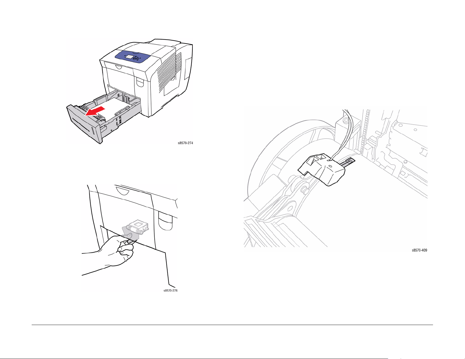
Clean the Pick Assembly
1. Remove Tray 2.
Figure 5 Removing Tray 2
2. Use a moistened lint-free cloth to clean the Pick Assembly. Be sure the Pick Assembly is
not damaged. Replace the Pick Assembly if it appears to be excessively worn or dam
aged.
Clean the Drum Temperature Sensor
CAUTION
Cleaning under the Sensor is not recommended. Only perform this procedure when there is an
issue with Drum temperatures (too hot or too cold) or there is a significant amount of debris
accumulated under the Sensor. Use care not to bend the Sensor.
1. Remove the Control Panel Cover (REP 1.5).
2. Remove the Left Side Cover (REP 1.10).
3. Remove the Right Side Cover (REP 1.11).
4. Remove the Exit Cover (REP 1.7).
5. Remove the Ink Loader (REP 1.8).
6. Remove the Exit Module (REP 3.13).
7. Using a dry swab, carefully clean the Sensor.
-
Figure 6 Cleaning the Pick Assembly
3. Close Tray 2.
Initial Issue
ColorQube 8570/8870 Service Manual
October 2010
1-11
Figure 7 Cleaning the Drum Temperature Sensor
Service Call Procedures
Cleaning Procedures
Page 46

Clean the Paper Release Blade
1. Open the Exit Cover.
Figure 8 Opening the Exit Cover
2. Lift the Paper Guide toward the front of the printer.
3. Use a moistened lint-free cloth to wipe the plastic paper release blade on the Lower Paper
Guide.
Figure 10 Cleaning the Paper Release Blade
4. Lower the Paper Guide to its original position.
5. Close the Exit Cover.
Figure 9 Opening the Lower Paper Guide
Service Call Procedures
Cleaning Procedures
October 2010
1-12
Figure 11 Lowering the Paper Guide and Closing the Exit Cover
Initial Issue
ColorQube 8570/8870 Service Manual
Page 47

Clean the Drum Maintenance Wiper Blade Assembly
1. Remove the Front Door (REP 1.1).
2. Remove the Control Panel Cover (REP 1.5).
3. Remove the Right Side Cover (REP 1.11).
4. Remove the Lower Inner Duplex Guide (REP 3.2).
5. Remove the Inner Simplex Guide with Deskew Sensor and Harness (REP 3.1).
6. Remove the Preheater and Deskew Assembly (REP 2.20).
7. Remove the Drum Maintenance Unit (REP 1.16).
8. Remove the Drum Cooling Fan (REP 4.12).
9. Remove the Drum Maintenance Pivot Plate/Drum Wiper Blade Assembly (REP 2.17).
10. Use a lint-free cloth to clean the top and sides of the flexible plastic Wiper Blade.
Final Actions
Purpose
The intent of this procedure is to be used as a guide to follow at the end of every service call.
Procedure
1. Check that the exterior of the printer and the adjacent area is clean. Use a dry cloth or a
cloth moistened with water to clean the exterior of the printer. Do not use solvents.
2. Check the supply of consumables. Ensure that an adequate supply of consumables is
available according to local operating procedures.
3. Conduct any operator training that is needed. Ensure the operator understands the periodic maintenance procedures in the User Guide.
4. Reconnect the printer to the customer network. Verify function by printing one or more
test prints. Present the test prints to the customer as examples of printer performance.
5. Discuss the service call with the customer to ensure that the customer understands what
has been done and is satisfied with the results of the service call.
Figure 12 Cleaning the Wiper Blade
Initial Issue
ColorQube 8570/8870 Service Manual
October 2010
1-13
Service Call Procedures
Cleaning Procedures, Final Actions
Page 48

Service Call Procedures
Cleaning Procedures, Final Actions
October 2010
1-14
Initial Issue
ColorQube 8570/8870 Service Manual
Page 49

Introduction ..................................................................................................................... 2-3
Power On Self Tests ....................................................................................................... 2-3
Print Engine Self-Test ..................................................................................................... 2-6
NVRAM Reset................................................................................................................. 2-7
Configuration Card Parameters ...................................................................................... 2-8
Fault Messages and Codes Troubleshooting.................................................................. 2-9
Testing Clutch, Motor, and Solenoid Resistance ............................................................ 2-10
Chain 10 - Drum
10,550 Y-Axis Fault......................................................................................................... 2-11
Chain 72 - Feeder, Tray 2
72,215 Tray 2 Raise Failure............................................................................................ 2-13
72,217 Tray 2 Bump-up Failure ...................................................................................... 2-13
Chain 73 - Feeder HCF1, Paper Path
73,215, 73,952 525-Sheet Feeder Faults ....................................................................... 2-15
Chain 74 - Feeder HCF2, Paper Path
74,215, 74,952 525-Sheet Feeder Faults ....................................................................... 2-17
Chain 75 - Feeder HFC3, Paper Path
75,215, 75,952 525-Sheet Feeder Faults ....................................................................... 2-19
Chain 88 - Preheater
88,500 ~ 88,504 Preheater Thermal Faults .................................................................... 2-21
Chain 89 - Registration Media Path
89,570, 89,571 Media Drive Faults ................................................................................. 2-23
89,572 Media Path Motor Fault....................................................................................... 2-23
Chain 91 - Marking Drawer/Unit
91,500 X-Axis Fault......................................................................................................... 2-25
91,523, 91,527, 91,531, 91,850, 91,862 Left Jetstack Thermal Faults........................... 2-25
91,535, 91,539, 91,543, 91,854, 91,866 Right Jetstack Thermal Faults......................... 2-26
91,547, 91,551, 91,555, 91,858, 91,870 Printhead Reservoir Thermal Faults ............... 2-27
91,610 Printhead Calibration Fault.................................................................................. 2-28
91,710 ~ 91,716, 94,704 Wiper or Media Drive Faults.................................................... 2-29
91,720 Printhead Tilt Fault .............................................................................................. 2-30
91,721 Printhead Tilt Fault .............................................................................................. 2-31
91,722 Printhead Tilt Fault .............................................................................................. 2-32
91,723 Printhead Tilt Fault .............................................................................................. 2-33
91,725 Process Drive Fault............................................................................................. 2-34
91,726 Process Drive Fault............................................................................................. 2-35
91,900, 91,903, 91,904, 93,901 Printhead NVRAM or PLD Fault................................... 2-36
Chain 92 - Electronics
92,500, 92,550, 92,555, 92,558 Electronics Module ....................................................... 2-37
92,553 Ink Loader or I/O Board Disconnected................................................................ 2-37
92,563, 92,570, 92,579 Electronics Module Faults ......................................................... 2-38
92,571 Software Fault..................................................................................................... 2-38
2 Fault Messages and Codes
92,587 Wave Amp Fault.................................................................................................. 2-39
92,588 ~ 92,596 Electronics Module Faults .................................................................... 2-40
92,597, 92,601 Electronics Module Faults ...................................................................... 2-40
92,604 ~ 92,606 Electronics Fan Faults.......................................................................... 2-41
92,607 ~ 92,609 Wave Amp Faults................................................................................. 2-41
92,808 ~ 92,813 Configuration Card Faults .................................................................... 2-42
92,900 Ink Loader Disconnect......................................................................................... 2-43
Chain 93 - Ink
93,501, 93,506, 93,511, 93,516 Ink Loader Faults.......................................................... 2-45
93,523, 93,526, 93,529, 93,532 Ink Loader Thermal Faults ........................................... 2-46
93,524, 93,527, 93,530, 93,533 Ink Loader Thermal Faults ........................................... 2-47
93,581 ~ 93,584 Printhead Level Sense Faults .............................................................. 2-48
93,597, 93,598, 93,599, 93,800 Printhead Level Sense Faults ...................................... 2-48
93,600, 93,603, 93,606, 93,609 Ink Loader Thermal Faults ........................................... 2-50
93,601, 93,604, 93,607, 93,610 Ink Loader Thermal Faults ........................................... 2-51
93,602, 93,605, 93,608, 93,611 Ink Loader Electrical Faults.......................................... 2-52
93,893 ~ 93,896 Ink Loader Faults ................................................................................. 2-52
93,962 ~ 93,965 Incorrect Ink Sticks............................................................................... 2-53
93,966 ~ 93,969 Unidentified Ink Sticks.......................................................................... 2-54
93,982 ~ 93,985 Ink Load Obstruction Faults ................................................................. 2-55
93,994 ~ 93,997 Ink Loader Faults ................................................................................. 2-56
Chain 94 - Drum Maintenance
94,510 ~ 94,513 Y-Axis Faults ........................................................................................ 2-59
94,524, 94,526 Y-Axis Faults .......................................................................................... 2-59
94,536, 94,538 ~ 94,541 Drum Thermal Faults .............................................................. 2-60
94,548, 94,550 Y-Axis Faults .......................................................................................... 2-61
94,570 Drum Maintenance Fault..................................................................................... 2-61
94,626 Drum Thermal Fault ............................................................................................ 2-62
94,700 Process Drive Fault ............................................................................................. 2-63
94,701, 94,702 Process Drive Faults .............................................................................. 2-64
94,703 X-Axis Fault ......................................................................................................... 2-64
94,704 Wiper and Media Drive Fault............................................................................... 2-65
Chain 99 - PEST
99,001 PEST - Generic Error .......................................................................................... 2-67
99,002, 99,003 PEST - Jetstack Disconnect................................................................... 2-67
99,004, 99,005 PEST - Reservoir Disconnect................................................................. 2-68
99,006 PEST - Drum Heater Disconnect ........................................................................ 2-69
99,008 PEST - Preheat Heater Disconnect..................................................................... 2-70
99,009 ~ 99,013 PEST - Ink Melters are Disconnected .................................................. 2-71
99,015 PEST - Drum Cooling Fan Disconnect ................................................................ 2-72
99,016 PEST - All Three Clutches Failed........................................................................ 2-73
99,017 PEST - Head Maintenance Clutch Disconnect.................................................... 2-74
99,018 PEST - Main Tray Deskew Clutch Disconnect .................................................... 2-74
99,019 PEST - Main Tray Pick Clutch Disconnect .......................................................... 2-75
99,020 PEST - Multipurpose Tray Pick Solenoid Disconnect ......................................... 2-75
99,021 PEST - Strip Solenoid Disconnect....................................................................... 2-76
Initial Issue
ColorQube 8570/8870 Service Manual
October 2010
2-1
Fault Messages and Codes
Page 50

99,022 PEST - Preheat Solenoid Disconnect ................................................................. 2-76
99,023 PEST - Head Tilt Solenoid Disconnect ............................................................... 2-77
99,024 PEST - Main Tray Elevator Disconnect............................................................... 2-77
99,030 ~ 99,034 PEST - X-Axis Motor Disconnect ......................................................... 2-78
99,035, 99,036 PEST - Y-Axis Motor Disconnect ........................................................... 2-78
99,037, 99,038 PEST - Media Path Motor Disconnect ................................................... 2-79
99,039, 99040 PEST - Process Motor Disconnect.......................................................... 2-79
99,042 ~ 99,051 PEST - Power Supply Faults................................................................ 2-80
99,052, 99,053 PEST - Power Supply +12V or -15V Faults ........................................... 2-81
99,056, 99,057 PEST - Power Supply +12 V Sleep Faults ............................................. 2-82
99,059, 99,060 PEST - VPP/ VSS Measurement Too Low ............................................ 2-83
99,061 PEST - The Wave Amp Shorted ......................................................................... 2-84
99,062 ~ 99,069 PEST - Ink Loader Solenoid Gate Push/Pull Disconnected................. 2-85
99,070 PEST - All Ink Loader Gates Failed .................................................................... 2-86
99,071 PEST - Power Dump Circuit Disconnected......................................................... 2-87
Fault Messages
Close Front Door A (when actually closed)..................................................................... 2-89
Close Exit Door B (when actually closed) ....................................................................... 2-89
Close Ink Loader Door C (when actually closed) ............................................................ 2-90
Paper Jam - Open Front Door to Clear (no jam is present and message won’t clear) ... 2-90
Paper Jam - Open Exit Door B to Clear (no jam is present and message won’t clear) .. 2-91
Tray 2 Empty (when it has paper) ................................................................................... 2-91
Tray 2 is Missing (when inserted) ................................................................................... 2-92
Unload Output Tray (when not full) ................................................................................. 2-92
Maintenance Kit Missing (when installed) ....................................................................... 2-93
Waste Tray Missing (when installed) .............................................................................. 2-93
Ink Sticks Jammed.......................................................................................................... 2-94
Remove Incorrect Ink Sticks (Cyan, Magenta, Yellow, Black) ........................................ 2-94
Remove Unidentified Ink Sticks (Cyan, Magenta, Yellow, Black) ................................... 2-95
Jam Codes ...................................................................................................................... 2-95
Printer Fault Codes ......................................................................................................... 2-100
Fault Messages and Codes
October 2010
2-2
Initial Issue
ColorQube 8570/8870 Service Manual
Page 51

Introduction
This chapter describes fault messages and numeric codes displayed on the Control Panel or
listed on the Fault History page. These fault indications serve as the entry point into the trou
bleshooting process.
Troubleshooting of problems not directly indicated by or associated with a fault message or
fault code is covered in Section 6 - General Troubleshooting. Print quality problems are covered
in Section 3 - Image Quality.
The printer tracks and reports errors in a number of ways. The two types of error reporting discussed in this chapter include:
• Fault codes and messages display on the Control Panel.
• Engine Error and Jam Error logs display on the Control Panel or listed on the Fault History
Report.
Check the main menu for current data and historical error data.
• Status Page
• Usage Profile
• Fault History
• Diagnostic History
Accessing Fault History Report
1. From the Control Panel Menu, select Troubleshooting -> Service Tools -> Printer Sta-
tus Page.
2. Press the OK button to print the Printer Status Page.
NOTE: The Printer Status Page contains a Printer Status, a Jam History & Fault History,
and a Light Stripes Test page.
Power On Self Tests
This section covers the start-up, Power-On Self Test (POST), Service Diagnostics, and power
-
supply operations of the printer to aid in troubleshooting problems not associated with a
reported error. For problems associated with a fault message, see Fault Messages and Codes
Troubleshooting. Troubleshooting tips are available at: www.xerox.com/support.
POST is the Power-On Self Test that runs during the boot process and prior to loading of the
operating systems (OS) and the Engine software regions. POST and the Boot loader share the
same OS and much of the same linkage.
Power-Up Fault Messages and LED Codes
The printer has two sets of tests that are performed when first powered on.
• Power-On Self Test (POST)
• Print Engine Self Test (PEST)
NOTE: POST errors are not stored in the Fault History logs.
In addition to the numeric fault codes appearing on the Control Panel display, the printer uses
the Control Panel, PostScript (PS), and Print Engine (PE) LEDs to communicate errors. Figure
1 shows location of the PS and PE LEDs on the Electronics Module. The PE/PS error LEDs
can be used to determine the problem with the printer when the Control Panel is not function
ing.
-
Fault History and Jam History Reports
The Fault History and Jam History Reports provide a list of error messages and fault codes
relating to Engine errors and Jam errors. The printer can retain up to 15 Engine errors and 20
Jam errors.
Examples
Table 1 Jam History
Date Page Count Code Description
Aug 3, 2009, 22:50:50 1098 R2F0 Unknown sensor, Sensor Tripped unexpect-
Table 2 Fault History
Date Page Count Code Description
Aug 3, 2009, 17:28:20 1018 93,603.00 Ink delivery and ink thermals
Initial Issue
ColorQube 8570/8870 Service Manual
edly, Fault, Unknown sensor
October 2010
2-3
Figure 1 Power-On Self Test and Print Engine LED Locations
Fault Messages and Codes
Introduction, Power On Self Tests
Page 52

POST Error Reporting
POST checks the communication path within the Electronics Module and to other various
printer components.
POST testing initializes the Control Panel, and in most cases if an error occurs, a text message
is displayed on the Control Panel along with an LED blink code flashing on all three LEDs
(Control Panel LED, PS LED and PE LED). If initialization of the Control Panel fails, POST
errors will still report using the LED blink patterns. The sum of the flashes equal the fault code.
If the code has more than 5 flashes, there is a brief pause between each set of 5 flashes to
make them easier to count. After all flashes occur within the code, there is a long pause and
then the flash pattern repeats.
All faults detected in POST are considered hard faults. In the event a fault is detected, then
POST will first write a message to the Control Panel LCD indicating the type of fault. This
assumes that the Control Panel is functioning otherwise the Control Panel activities are
bypassed. As a final action, POST will then flash the fault type to the Control Panel LED and
the LED located on the Controller Board indefinitely. The operator will need to power-down the
printer to stop POST from flashing the LED.
“Soft” POST errors, that do not prevent the printer from powering up completely, are displayed
on the Control Panel for 5 seconds, and then the printer continues through the remainder of
POST. There are no rear panel LED codes associated with soft errors. Most soft errors will
cause the printer to print a Startup Page with the error message on it.
The Main Controller Board includes a debug serial port for use in development. It can also be
used by manufacturing and service as well. Depending on the condition of the printer, the
debug serial port may or may not function.
Supported POST Tests
The following list contains tests that are performed in the context of POST.
• Field Pre-programmable Gate Array (FPGA) Testing
NOTE: FPGA is the Printhead interface and motor controller for the ColorQube 8570/
8870 printer.
1. Verifies FPGA loaded properly.
2. Reads chip ID and number.
3. Tests Image Output (IO) read and write.
4. Tests interrupt.
• Electronically Erasable Programmable Read-Only Memory (EEPROM) Testing
1. Tests read and write.
• Control Panel
1. Tests link valid.
2. Tests FP init.
3. Tests data path.
• Real Time Clock
1. Halts Clock and verify halted and attempt to restart.
2. Checks that clock can be read.
3. Checks trickle charge register.
•RAM Size
1. Verifies minimum amount of RAM.
Control Panel LCD Notification
POST attempts to write to the Control Panel LCD. This is the primary notification method for
conveying faults detected in POST.
Fault Messages and Codes
Power On Self Tests
October 2010
2-4
Initial Issue
ColorQube 8570/8870 Service Manual
Page 53

Control Panel LED Notification
As a secondary method of notification, POST will write blink codes to the Control Panel and
Controller Board LEDs. This is a backup notification system in the event the Control Panel can
not be written.
The LED blink method encodes a fault code number into a series of flashes that can be read as
that fault number. For example a fault code number 0x254 would be flashed using the following
blink sequence.
1. Start by fluttering the LED, this indicates that start of the blink sequence.
2. Pause by turning off the LED for a brief period of time.
3. Flash the LED with 2 consecutive blinks.
4. Pause between digits.
5. Flash the LED with five consecutive blinks.
6. Pause between digits.
7. Flash the LED with four consecutive blinks.
8. Pause between digits.
9. Start sequence over at step 1.
Using this blink method requires that no fault codes contain a zero digit.
Detected POST Faults
Tabl e 1 lists possible detected errors and their associated fault codes.
-
NOTE: POST error 226 can indicate blown Fuse F501 in the Electronics Module, or Control
Panel is unplugged or its cable is damaged.
Table 1 POST Error Type
Description Fault Code
POST_BAD_ERROR_CODE 211
POST_RTC_READ_FAILURE 212
POST_RTC_WRITE_FAILURE 213
POST_RTC_REREAD_FAILURE 214
POST_RTC_NOT_TICKING 215
POST_RTC_TRICKLE_CHRG_FAILURE 216
POST_EEPROM_READ_FAILURE 217
POST_EEPROM_WRITE_FAILURE 218
POST_EEPROM_REREAD_FAILURE 219
POST_EEPROM_DATA_FAILURE 221
POST_RAM_INSUFFICIENT 222
POST_FP_LINK_INVALID 223
POST_FP_WONT_INIT 225
POST_FP_DATA_PATH_FAILURE 226
POST_PROG_MACHINE_CHECK 227
POST_FPGA_LOAD_FAILURE 228
POST_FPGA_ID_READ_FAILURE 229
POST_FPGA_ID_MISMATCH 231
POST_FPGA_WRITE_MISMATCH 232
POST_FPGA_INTERRUPT_FAIL 233
POST_FPGA_ACCESS_FAIL 234
Initial Issue
ColorQube 8570/8870 Service Manual
October 2010
2-5
Fault Messages and Codes
Power On Self Tests
Page 54

Sequence
The following sequence describes the operational steps just prior to, during, and just after the
loading of POST stand-alone code. Whenever any of the following sequence steps fail, POST
will halt at the failed test, writes the failed test fault code to the Control Panel LCD and flashes
the Control Panel LED with the associated blink code.
1. When power is turned on, the Control Panel LED is turned off and dim. The Control Panel
LCD is blank.
2. The Boot loader is run.
3. The Boot loader loads the flash image of FPGA.
4. The Boot loader loads and runs the POST stand-alone code.
5. POST turns on the Electronics Module Fan full. The Fan remains on until the Engine
region is loaded and PEST takes over control of the Fan.
6. POST checks the load status of FPGA.
7. POST turns LEDs off.
8. POST checks if the Control Panel link is valid.
a. If valid attempt to initialize the Control Panel. Verify LCD data connection is OK. Dis-
play Control Panel header. POST checks for POST Cancel button from the Control
Panel. If cancel received, exits POST and return control back to the Boot loader.
b. If invalid skips initializing the Control Panel.
9. POST attempts to read config space by reading FPGA’s vendor ID.
10. POST attempts to read and write a defined FPGA register.
11. POST attempts to interrupt FPGA.
12. POST attempts EEPROM tests.
13. POST attempts Real Time Clock tests.
14. POST checks RAM size.
15. POST sets the Control Panel LED on green.
16. POST stand-alone code exits and returns control back to the Boot loader.
17. The OS is loaded.
Print Engine Self-Test
Print Engine Self-Test (PEST) tests components if they are drawing power. PEST tests occur
after POST tests have been run and PostScript has been initialized. PEST checks the connec
tions and operation of various components. PEST runs as part of the print engine.
PEST Error Reporting
Fault codes for PEST are displayed on the Control Panel and are in the 99,XXX series. For
troubleshooting PEST fault codes, see Fault Messages and Codes Troubleshooting.
-
Fault Messages and Codes
Power On Self Tests, Print Engine Self-Test
October 2010
2-6
Initial Issue
ColorQube 8570/8870 Service Manual
Page 55

NVRAM Reset
Many of the troubleshooting procedures in this section include an NVRAM reset as a procedural step. Following an NVRAM reset, the printer is unable to communicate on the network
and has lost several parameters specific to the customer’s configuration. If possible, print a
Configuration page to capture networking parameters. and discuss the customer’s configura
tion to document these settings before resetting NVRAM.
Ta b l e 1 lists the parameters reset by NVRAM Reset. Required parameters (Yes) must be con-
figured to restore default printer operation on the network.
Table 1 Parameters Reset with Service Diagnostics NVRAM Reset Command
Menu Parameter Default Required Comment
TCP/IPv4 Setup IPv4 On Ye s
DHCP/BOOTP On Ye s
AutoIP On Ye s
IPv4 Address 0.0.0.0 Ye s Set automati-
IPv4 Network Mask 0.0.0.0 Ye s Automatically
IPv4 Gateway 0.0.0.0 Ye s Automatically
TCP/IPV6 Setup IPv6 Disabled Ye s
Auto Assign On Ye s Applicable
Manual Address Off Yes Appears when
Network Services
Network Setup Ethernet Speed Auto Ye s
USB Setup USB Port On Ye s
Port 9100 On Ye s
LPR On Ye s
IPP On Ye s
FTP On Ye s
TFTP On Ye s
WSD On Ye s
SLP Off Ye s
SSDP Off Ye s
CentreWare IS On Ye s
IPSec Off Ye s
EtherTalk On Ye s
Wait Timeout 30 secs Ye s
cally if DHCP/
BOOTP is
enabled
calculated
based on IP
Address
set per RIP.
when IPv6 is
enabled.
IPv6 is enabled.
Table 1 Parameters Reset with Service Diagnostics NVRAM Reset Command
Menu Parameter Default Required Comment
Page Description Language AutoSelect Ye s
Control Panel
Setup
File Security Overwrite Removals Off No
Paper Handling
Setup
Printer Controls Startup Page On No
Paper Tray Setup Tray 1 Paper - Media Size Guide Size No
Language English No
Control Panel Brightness 8 No
Control Panel Contrast 5 No
Accessible Control panel Off No
Menu Timeout 30 secs No
Daily Removal Off No
Age-based Removal Off No
Paper Source Auto
Select
2-Sided Printing Off No
Load Paper Timeout 3 mins No
Letter/A4 Substitution On No
Custom Units Inches No
Cleaning Page Source Highest No
Low Ink Warning Level 1000 No
Date and Time NA No Set by on-board
Warm-up Mode Intelligent
Ready
Metric Defaults Off No
Fast Resume Off No
Tray 1 Paper - Media Type Plain No
Tray 2 Paper Type Plain No
Tray 3 Paper - (if installed) Plain No
Tray 4 Paper - (if installed) Plain No
Tray 5 Paper - (if installed) Plain No
Tray 1 Mode Dynamic No
Tray 1 Prompt 30 secs No
Tray 2 Mode Dynamic No Dependent on
Tray 2-3 Mode Dynamic No Dependent on
Tray 2-4 Mode Dynamic No Dependent on
No
No
RTC.
number of
installed trays.
number of
installed trays.
number of
installed trays.
Initial Issue
ColorQube 8570/8870 Service Manual
October 2010
2-7
Fault Messages and Codes
NVRAM Reset
Page 56

Table 1 Parameters Reset with Service Diagnostics NVRAM Reset Command
Menu Parameter Default Required Comment
Tray 2-5 Mode Dynamic No Dependent on
number of
installed trays.
PostScript Setup PostScript Error Info Off No
Print-Quality Mode Enhanced No
Color-Correction Automatic No
User-Defined Screens Off No
PCL Setup Font Number 0 No
Pitch 10 No
Point Size 12 No
Symbol Set PC-8 No
Orientation Portrai t No
Form Length 60 No
Line Termination On No
Enhanced Mode Off No
Color Mode Color No
Wide A4 Off No
Ta b l e 2 summarizes printer parameters not affected by an NVRAM Reset.
Table 2 Parameter Not Affected by an NVRAM Reset
Parameter Comment
Metric Defaults Set to Off, default sizes are interpreted in inches.
MAC Address Set by the Configuration Card.
Serial Number
Model Number
License Number
VxWorks Version
PostScript Version
PostScript Revision
Engine Version
Network Version
Activision Date
Print Count
Billing Meters
Substituted Jets
Warm-up Mode Set to Intelligent Ready
Warm-up Settings Set to Job Activated
Stand-by Settings Set to idle after timeout
Configuration Card Parameters
Information stored on the Configuration Card includes the ethernet address and personality
parameters. The printer model configuration is determined by a combination of printer hard
ware capabilities. Feature value and ethernet address are configured at the factory and are
“read only”. The feature value is fixed in the Configuration Card and does not change. Ethernet
address is stored only on the Configuration Card and cannot be rewritten. The ethernet
address is not written to the NVRAM chip.
Personality parameters are a subset of network configuration parameters, which are populated
to the Configuration Card over time as the printer is configured by the customer. The personal
ity parameters are copied, or “shadowed”, from the Main Controller Board's NVRAM Chip to
the Configuration Card during the normal operation of the printer. When the Configuration Card
is inserted into a new printer, the personality parameters on the Configuration Card are written
into the NVRAM Chip of the new printer. When a printer is powered on, if it contains the Config
uration Card of another printer, the personality parameters are automatically copied to the
NVRAM Chip. If the Configuration Card is removed, the printer reboots as a non-networking,
non-duplexing model.
-
-
-
Fault Messages and Codes
NVRAM Reset, Configuration Card Parameters
October 2010
2-8
Initial Issue
ColorQube 8570/8870 Service Manual
Page 57

Fault Messages and Codes Troubleshooting
This section covers troubleshooting procedures utilizing Control Panel fault messages and
codes. Some procedures require running Service Diagnostic test functions to verify that a com
ponent is operating correctly. Procedures that direct a test to be run are referencing tests from
within the Hidden Service menu. For information on Service Diagnostics, see Service Diagnos
tics in Chapter 6 - General Troubleshooting.
For troubleshooting problems not associated with a fault code or message, such as startup or
power on, media, paper path, print-quality or image problems, and electrical failures, see Gen
eral Troubleshooting in Chapter 6.
Fault Code Error Reporting
Fault codes are saved to NVRAM and can be retrieved from the printer’s fault history.
In normal customer mode, the printer will reboot each time a fault occurs. If three of the same
faults occur within 72 hours, or 1000 pages, the fault will be displayed on the printer’s Control
Panel.
Interpreting Fault Codes
• Failing system (XX,yyy.00)
• Failing subsystem (xx,YYY.00)
• Print engine page count when the error occurred (xx,yyy.00:123)
Device faults indicate a hardware problem. The most common device faults troubleshooting
procedures are documented in this chapter.
Software faults occur when the printer has a corrupted data, incorrect instructions, errors in
floating point math, or the execution of code that should not have been reached. Sometimes
this is caused by hardware but it is usually due to a problem with software. Most of the time a
reboot of the printer will fix these problems. All software errors are combined into one fault
code, 92,571, and if they are chronic that error will be displayed on the Control Panel.
Fault Code Definition
Fault Code contains Chain number (0-99) and Link number (0-999).
-
• Chain Number - indicates target feature area.
-
• Link Number - The fault type is defined by the Link number.
Table 1 Chain Definition
Chain Sub-system Definition
-
1 System Power and Interlock
10 Drum Transfix, Post Transfix, Media Path
71 Feeder MPT Tray 1 (M P T )
72 Feeder MT Tra y 2
73 Feeder HCF1 - Paper Path HCF1 Tray 3
74 Feeder HCF2 - Paper Path HCF2 Tray 4
75 Feeder HCF3 - Paper Path HCF3 Tray 5
82 Prereg MP Media path up to Registration
83 Duplex Duplex portion of Media Path
88 Preheater Preheater
89 Reg MP Registration portion media path
91 MARKDWR Components in the marking drawer/unit.
92 Electronic Electronics not specific to another chain
93 Ink Ink delivery and Ink Thermals
94 Drum Maintenance Drum, Stripper, Drum Maintenance
99 PEST Print Engine Self-Test
Initial Issue
ColorQube 8570/8870 Service Manual
October 2010
2-9
Fault Messages and Codes
Fault Messages and Codes Troubleshooting
Page 58

Testing Clutch, Motor, and Solenoid Resistance
1. Turn off the printer and disconnect the power cord.
2. With a Digital Multimeter (DMM) set for measuring resistance, test each motor’s windings
for correct resistance (disconnected from the printer). Rotate the motor’s drive shaft
slightly while taking the measurement.
Table 1 Clutch, Motor, and Solenoid Resistance
Clutch, Motor, and
Solenoid
Head Maintenance Clutch 186 ohms +/- 15%
Paper-Pick Clutch
Deskew Clutch
Process Drive Motor
Media Path Drive Motor
Tray Lift Motor 50~500 ohms
X-Axis Motor 5.9 ohms/phase +/- 10% (pins 2 to 4 and pins 3 to 5)
Y-Axis Motor 1.05~1.43 ohms (Difficult to measure due to variability at the
MPT Pick Solenoid 124 ohms +/- 5%
Ink Loader Solenoid ~10 ohms blue-red, ~10 ohms yellow-red, ~20 ohms blue-yellow
Preheater Lift Solenoid ~18 ohms blue-red, ~18 ohms yellow-red, ~36 ohms blue-yellow
186 ohms +/- 15%
2.85~3.85 ohms (Difficult to measure due to variability at the
brush/commutator interface.)
brush/commutator interface.)
Resistance (approximate)
Fault Messages and Codes
Testing Clutch, Motor, and Solenoid Resistance
October 2010
2-10
Initial Issue
ColorQube 8570/8870 Service Manual
Page 59

10,550 Y-Axis Fault
A Y-Axis error has occurred. The following troubleshooting procedure applies to this error.
Table 1 Applicable Fault Code
10,550 Drum Stall
Initial Actions
• Reboot the printer and verify the error persists.
• Check all the Drum cable connections.
• If the problem persists, perform the following procedure.
Troubleshooting Reference
Applicable Parts (Chapter 5 - Parts List)
• Drum Assembly, PL 2.1 Item 4
• Y-Axis Motor Assembly, PL 4.1 Item 2
• Harness, Right Side Power Control, PL 5.1 Item 13
Wiring and Plug/Jack References (Chapter 7 - Wiring Data)
• Figure 1, Right Side Wire Routing
• Figure 6, Hard Drive, Drum Heater, Paper Preheater
• Figure 7, Drum Heater Load Dump, Motors, Head Maintenance Clutch, Strip Solenoid
Procedure
Verify that user is setting correct paper type when running thick media or envelopes. Does the
media selection have the correct media type?
YN
Set the correct media type.
Check the Drum power and encoder wiring harness connectors P/J114, P/J120, and P/J122.
Are the connections secure and undamaged?
YN
Reseat and/or repair the wiring harnesses.
Clean the Y-Axis Belt and Pulley with Isopropyl Alcohol. Turn on the printer. Does the error
persist?
YN
Troubleshooting complete.
Replace the Drum Assembly (REP 2.4). Does the error persist?
YN
Troubleshooting complete.
Replace the Y-Axis Motor Assembly (REP 4.2).
Initial Issue
ColorQube 8570/8870 Service Manual
October 2010
2-11
Fault Messages and Codes
10,550
Page 60

Fault Messages and Codes
10,550
October 2010
2-12
Initial Issue
ColorQube 8570/8870 Service Manual
Page 61

72,215 Tray 2 Raise Failure
A Tray 2 error has occurred. The following troubleshooting procedure applies to this error.
72,217 Tray 2 Bump-up Failure
A Tray 2 error has occurred. The following troubleshooting procedure applies to this error.
Table 1 Applicable Fault Code
72.215 Tray 2 Raise Failure
Initial Actions
• Reboot the printer and verify the error persists.
• Check the paper path in the printer for obstructions or jammed sheets.
• If the problem persists, perform the following procedure.
Troubleshooting Reference
Applicable Parts (Chapter 5 - Parts List)
• 525-Sheet Tray, PL 3.1 Item 11
• Tray 2 Lift Motor, PL 4.1 Item 6
• Sensor, Tray Lift, PL 6.1 Item 3
Procedure
Reinsert Tray 2. Does the error persist?
YN
Troubleshooting complete.
Check Tray 2 Lift Sensor for blockages, and check function of the Tray 2 Lift Motor.
Table 1 Applicable Error Code
72,217 Tray 2 Bump Failure
Initial Actions
• Reboot the printer and verify the error persists.
• Check the paper path in the printer for obstructions or jammed sheets.
• If the problem persists, perform the following procedure.
Troubleshooting Reference
Applicable Parts (Chapter 5 - Parts List)
• 525-Sheet Tray, PL 3.1 Item 11
• Tray 2 Lift Motor, PL 4.1 Item 6
• Sensor, Tray Lift, PL 6.1 Item 3
Procedure
Reinsert Tray 2. Does the error persist?
YN
Troubleshooting complete.
Check Tray 2 Lift Sensor for blockages, and check function of the Tray 2 Lift Motor.
Initial Issue
ColorQube 8570/8870 Service Manual
October 2010
2-13
Fault Messages and Codes
72,215, 72,217
Page 62

Fault Messages and Codes
72,215, 72,217
October 2010
2-14
Initial Issue
ColorQube 8570/8870 Service Manual
Page 63

73,215, 73,952 525-Sheet Feeder Faults
A 525-Sheet Feeder error has occurred. The following troubleshooting procedure applies to
these errors.
Table 1 Applicable Fault Codes
73,215 HCF1 Raise Failure
73,952 HCF1 Motor Stall Fault
Initial Actions
• Reboot the printer and verify the error persists.
• Check paper path in the printer and High-Capacity Feeders (HCFs) for obstructions or
jammed sheets.
• If the problem persists, perform the following procedure.
Troubleshooting Reference
Applicable Parts (Chapter 5 - Parts List)
• 525-Sheet Feeder (HCF) with Tray, PL 3.1 Item 12
• Harness, Left Side Power Control, PL 5.1 Item 17
Wiring and Plug/Jack Reference (Chapter 7 - Wiring Data)
• Figure 2, Left Side Wire Routing
Procedure
Check paper path in the printer and HCFs for obstructions or jammed sheets. Remove obstructions.
• For HCF Motor Stall failure, send a print job to feed paper from the tray at fault.
• For HCF Raise failure, reinsert the tray and verify that it raised properly.
Does the error persist?
YN
Troubleshooting complete.
Replace the 525-Sheet Feeder (REP 3.12).
Initial Issue
ColorQube 8570/8870 Service Manual
October 2010
2-15
Fault Messages and Codes
73,215, 73,952
Page 64

Fault Messages and Codes
73,215, 73,952
October 2010
2-16
Initial Issue
ColorQube 8570/8870 Service Manual
Page 65

74,215, 74,952 525-Sheet Feeder Faults
A 525-Sheet Feeder error has occurred. The following troubleshooting procedure applies to
these errors.
Table 1 Applicable Fault Codes
74,215 HCF2 Raise Failure
74,952 HCF2 Motor Stall Fault
Initial Actions
• Reboot the printer and verify the error persists.
• Check paper path in the printer and HCFs for obstructions or jammed sheets.
• If the problem persists, perform the following procedure.
Troubleshooting Reference
Applicable Parts (Chapter 5 - Parts List)
• 525-Sheet Feeder (HCF) with Tray, PL 3.1 Item 12
• Harness, Left Side Power Control, PL 5.1 Item 17
Wiring and Plug/Jack Reference (Chapter 7 - Wiring Data)
• Figure 2, Left Side Wire Routing
Procedure
Check paper path in the printer and HCFs for obstructions or jammed sheets. Remove obstructions.
• For HCF Motor Stall failure, send a print job to feed paper from the tray at fault.
• For HCF Raise failure, reinsert the tray and verify that it raised properly.
Does the error persist?
YN
Troubleshooting complete.
Replace the 525-Sheet Feeder (REP 3.12).
Initial Issue
ColorQube 8570/8870 Service Manual
October 2010
2-17
Fault Messages and Codes
74,215, 74,952
Page 66

Fault Messages and Codes
74,215, 74,952
October 2010
2-18
Initial Issue
ColorQube 8570/8870 Service Manual
Page 67

75,215, 75,952 525-Sheet Feeder Faults
A 525-Sheet Feeder error has occurred. The following troubleshooting procedure applies to
these errors.
Table 1 Applicable Fault Codes
75,215 HCF3 Raise Failure
75,952 HCF3 Motor Stall Fault
Initial Actions
• Reboot the printer and verify the error persists.
• Check paper path in the printer and HCFs for obstructions or jammed sheets.
• If the problem persists, perform the following procedure.
Troubleshooting Reference
Applicable Parts (Chapter 5 - Parts List)
• 525-Sheet Feeder (HCF) with Tray, PL 3.1 Item 12
• Harness, Left Side Power Control, PL 5.1 Item 17
Wiring and Plug/Jack Reference (Chapter 7 - Wiring Data)
• Figure 2, Left Side Wire Routing
Procedure
Check paper path in the printer and HCFs for obstructions or jammed sheets. Remove obstructions.
• For HCF Motor Stall failure, send a print job to feed paper from the tray at fault.
• For HCF Raise failure, reinsert the tray and verify that it raised properly.
Does the error persist?
YN
Troubleshooting complete.
Replace the 525-Sheet Feeder (REP 3.12).
Initial Issue
ColorQube 8570/8870 Service Manual
October 2010
2-19
Fault Messages and Codes
75,215, 75,952
Page 68

Fault Messages and Codes
75,215, 75,952
October 2010
2-20
Initial Issue
ColorQube 8570/8870 Service Manual
Page 69

88,500 ~ 88,504 Preheater Thermal Faults
A Preheater Thermal error has occurred. The following troubleshooting procedure applies to
these errors.
Table 1 Applicable Fault Codes
88,500 Preheat heater is too hot.
88,501 Preheat is heating too slow.
88,502 Preheat thermistor is bad.
88,503 Preheater thermistor is open.
88,504 Preheater thermistor is shorted.
Initial Actions
• Reboot the printer and verify the error persists.
• Check the ambient room temperature.
• Check that the Preheater is plugged in.
• If the problem persists, perform the following procedure.
Troubleshooting Reference
Applicable Parts (Chapter 5 - Parts List)
• Preheater and Deskew Assembly, PL 2.1 Item 20
• Right Side Power Control Harness, PL 5.1 Item 13
Wiring and Plug/Jack References (Chapter 7 - Wiring Data)
• Figure 6, Hard Drive, Drum Heater, Paper Preheater
• Figure 9, I/O Board, Sensors (2 of 2)
Procedure
Verify that the ambient temperature is within environmental specifications (refer to Environmen-
tal Specifications in the Introduction Chapter. Is the temperature within specifications?
YN
Advise customer of operational requirements.
B
Replace the Preheater and Deskew Assembly (REP 2.20).
Replace the Right Side Power Control Harness.
Figure 1 Measuring the Preheater Thermistor
Check the Preheater wiring harness connectors P/J115 and P/J125. Are the connections
secure and undamaged?
YN
Reseat and/or replace the wiring harnesses.
Check the Right Side Power Control Harness for damage. Is the Right Side Power Control
Harness damaged?
YN
Check the Preheater Thermistor for continuity.
• Disconnect the wiring harness connector P/J401 from the I/O Board.
• Measure the connector between pins 1 (red) and 2 (red). The measurement should
be about 110 ohms at room temperature.
Does the error persist?
YN
Troubleshooting complete.
AAB
Initial Issue
ColorQube 8570/8870 Service Manual
October 2010
2-21
Fault Messages and Codes
88,500 ~ 88,504
Page 70

Fault Messages and Codes
88,500 ~ 88,504
October 2010
2-22
Initial Issue
ColorQube 8570/8870 Service Manual
Page 71

89,570, 89,571 Media Drive Faults
A Media Drive error has occurred. The following troubleshooting procedure applies to these
errors.
89,572 Media Path Motor Fault
A Media Path Motor error has occurred. The following troubleshooting procedure applies to this
error.
Table 1 Applicable Fault Codes
89,570 Media Path Over Current Fault
89,571 Media Path Stall Fault
Initial Actions
• Reboot the printer and verify the error persists.
• Check the Media Drive wiring harnesses.
• Check the printer for jammed sheet in the paper path.
• If the problem persists, perform the following procedure.
Troubleshooting Reference
Applicable Parts (Chapter 5 - Parts List)
• Exit Roller, PL 3.1 Item 6
• Takeaway Roller, PL 3.1 Item 7
• Duplex Roller, PL 3.1 Item 8
• Media Drive with 2 Clutches, PL 4.1 Item 5
• Left Side Power Control Harness, PL 5.1 Item 17
Wiring and Plug/Jack Reference (Chapter 7 - Wiring Data)
• Figure 2, Left Side Wire Routing
Procedure
Remove the Media Drive Assembly (REP 4.5) and turn each printer Shaft by hand. Do you
feel any unusual resistance?
YN
Troubleshooting complete.
Table 1 Applicable Fault Code
89,572 Media Path Motor/ Wiring Fault
Initial Actions
• Reboot the printer and verify the error persists.
• Check the Media Drive wiring harnesses.
• If the problem persists, perform the following procedure.
Troubleshooting Reference
Applicable Parts (Chapter 5 - Parts List)
• Media Drive with 2 Clutches, PL 4.1 Item 5
• Left Side Power Control Harness, PL 5.1 Item 7
Wiring and Plug/Jack Reference (Chapter 7 - Wiring Data)
• Figure 2, Left Side Wire Routing
Procedure
Inspect the Motor Cable for bent pins, loose connections or damaged wires. Does the error
persist?
YN
Troubleshooting complete.
Replace the Media Drive Assembly (REP 4.5). Does the error persist?
YN
Troubleshooting complete.
Replace the Left Side Power Control Harness.
Clear the obstruction or replace the defective Drive Shaft or Bushing (see Mechanical Hardware Kit in Chapter 5, Parts List). Does the error persist?
YN
Troubleshooting complete.
Replace the Media Drive Assembly (REP 4.5).
Initial Issue
ColorQube 8570/8870 Service Manual
October 2010
2-23
Fault Messages and Codes
89,570, 89,571, 89,572
Page 72

Fault Messages and Codes
89,570, 89,571, 89,572
October 2010
2-24
Initial Issue
ColorQube 8570/8870 Service Manual
Page 73

91,500 X-Axis Fault
An X-Axis error has occurred. The X-Axis position is 0.0254 mm away from desired position.The following troubleshooting procedure applies to this error.
Table 1 Applicable Fault Code
91,500 Sfwa Image Initial Position
Initial Actions
• Reboot the printer and verify the error persists.
• If the problem persists, perform the following procedure.
Troubleshooting Reference
Applicable Parts (Chapter 5 - Parts List)
• X-Axis Motor, PL 4.1 Item 11
• Harness, Right Side Power Control, PL 5.1 Item 13
Wiring and Plug/Jack References (Chapter 7 - Wiring Data)
• Figure 1, Right Side Wire Routing
• Figure 7, Motors, Head Maintenance Clutch, Strip Solenoid
Procedure
Check the X-Axis wiring harness and connections. Are the connections secure and undamaged?
YN
Reseat and/or replace the Right Side Harness.
Replace the X-Axis Motor (REP 4.11).
91,523, 91,527, 91,531, 91,850, 91,862 Left Jetstack Thermal Faults
A Left Jetstack Thermal error has occurred. The following troubleshooting procedure applies to
these errors.
Table 1 Applicable Fault Codes
91,523 Left Jetstack Heater is too hot.
91,527 Left Jetstack Heater too slow, did not stabilize in time.
91,531 Left Jetstack Thermistor bad reading, cannot trust temperature.
91,850 Left Jetstack Thermistor is open.
91,862 Left Jetstack thermistor is shorted.
Initial Actions
• Reboot the printer and verify the error persists.
• Check the Printhead wiring harness connectors.
• If the problem persists, perform the following procedure.
Troubleshooting Reference
Applicable Parts (Chapter 5 - Parts List)
• Printhead Assembly, PL 2.1 Item 3
• Cable, Printhead Interface, PL 5.1 Item 20
Wiring and Plug/Jack References (Chapter 7 - Wiring Data)
• Figure 2, Wave Amplifier, Printhead
• Figure 6, Printhead P/J Locations
Procedure
Check the Printhead wiring harness connectors P/J180 and P/J240 and wiring. Are the connections secure and undamaged?
YN
Reseat and/or replace the wiring harness (Printhead Interface Cable). Does the error
persist?
YN
Troubleshooting complete.
Initial Issue
ColorQube 8570/8870 Service Manual
Turn off the printer.
Check the Thermistor for continuity on P/J110 connector (see Figure 1).
• Short pin 4 to pin 10.
• Measure the Thermistor to ground.
• Check the results as follows:
October 2010
2-25
Replace the Printhead Assembly (REP 2.3).
– Pin 2 (Left Jetstack Thermistor) to pin 4
– Good: 4.88 kohms at room temperature (The Printhead must be cool.)
– Open: >5 kohms
– Short: 0 ohms
Fault Messages and Codes
91,500, 91,523, 91,527, 91,531, 91,850, 91,862
Page 74

Does the error persist?
YN
Troubleshooting complete.
Replace the Printhead Assembly (REP 2.3).
Figure 1 Printhead Wiring Harness Connectors
91,535, 91,539, 91,543, 91,854, 91,866 Right Jetstack Thermal Faults
A Right Jetstack Thermal error has occurred. The following troubleshooting procedure applies
to these errors.
Table 1 Applicable Fault Codes
91,535 Right Jetstack Heater is too hot.
91,539 Right Jetstack Heater is too slow, did not stabilize in time.
91,543 Right Jetstack Thermistor bad reading, cannot trust temperature.
91,854 Right Jetstack Thermistor is open.
91,866 Right Jetstack Thermistor is shorted.
Initial Actions
• Reboot the printer and verify the error persists.
• Check the Printhead wiring harness connectors.
• If the problem persists, perform the following procedure.
Troubleshooting Reference
Applicable Parts (Chapter 5 - Parts List)
• Printhead Assembly, PL 2.1 Item 3
• Cable, Printhead Interface, PL 5.1 Item 20
Wiring and Plug/Jack References (Chapter 7 - Wiring Data)
• Figure 2, Wave Amplifier, Printhead
• Figure 6, Printhead P/J Locations
Procedure
Check the Printhead wiring harness connectors P/J180 and P/J240 and wiring. Are the connections secure and undamaged?
YN
Reseat and/or replace the wiring harness (Printhead Interface Cable). Does the error
persist?
YN
Troubleshooting complete.
Fault Messages and Codes
91,523, 91,527, 91,531, 91,850, 91,862, 91,535, 91,539,
Turn off the printer.
Check the Thermistor for continuity on P/J110 connector (see Figure 1).
• Short pin 4 to pin 10.
• Measure the Thermistor to ground.
• Check the results as follows:
October 2010
2-26
Replace the Printhead Assembly (REP 2.3).
– Pin 1 (Right Jetstack Thermistor) to pin 4
– Good: 4.88 kohms at room temperature (The Printhead must be cool.)
– Open Thermistor: 4.99 kohms
– Shorted Thermistor: 0 Ohm
Initial Issue
ColorQube 8570/8870 Service Manual
Page 75

Does the error persist?
YN
Troubleshooting complete.
Replace the Printhead Assembly (REP 2.3).
Figure 1 Printhead Wiring Harness Connectors
Initial Issue
ColorQube 8570/8870 Service Manual
91,547, 91,551, 91,555, 91,858, 91,870 Printhead Reservoir Thermal Faults
A Printhead Reservoir Thermal error has occurred. The following troubleshooting procedure
applies to these errors.
91,547 Reservoir Heater is too hot.
91,551 Reservoir Heater is too slow.
91,555 Reservoir Heater thermistor is bad.
91,858 Reservoir thermistor is open.
91,870 Reservoir thermistor is shorted.
Initial Actions
• Reboot the printer and verify the error persists.
• Check the Printhead wiring harness connectors.
• If the problem persists, perform the following procedure.
Troubleshooting Reference
Applicable Parts (Chapter 5 - Parts List)
• Printhead Assembly, PL 2.1 Item 3
• Cable, Printhead Interface, PL 5.1 Item 20
Wiring and Plug/Jack References (Chapter 7 - Wiring Data)
• Figure 2, Wave Amplifier, Printhead
• Figure 6, Printhead P/J Locations
Procedure
Restart the printer and allow to warm up. Check the Reservoir Thermistor wiring harness connector P/J190 (2-pin) on the Printhead Board. Is the connection secure and undamaged?
YN
Check the Printhead wiring harness connectors P/J180 and P/J240 and wiring. Are the connections secure and undamaged?
YN
A B
October 2010
2-27
Table 1 Applicable Fault Codes
Reseat and/or replace the wiring harness (Printhead Interface Cable).
Turn off the printer.
Check the Thermistor for continuity on P/J110 connector (see Figure 1).
• Short pin 4 to pin 10.
• Measure the Thermistor to ground.
– Pin 3 (Reservoir Thermistor) to pin 4
• Check the results as follows:
– Good: 4.88 kohms at room temperature (The Printhead must be cool.)
– Open Thermistor: 4.99 kohms
– Shorted Thermistor: 0 Ohm
Does the error persist?
YN
Troubleshooting complete.
Fault Messages and Codes
91,535, 91,539, 91,543, 91,854, 91,866, 91,547,
Page 76

A B
Replace the Printhead Assembly (REP 2.3).
Replace the Printhead Assembly (REP 2.3).
Figure 1 Wiring Harness Connectors
91,610 Printhead Calibration Fault
A Printhead Calibration error has occurred. The following troubleshooting procedure applies to
this error.
Table 1 Applicable Fault Code
91,610 Head Calibration Fault
Initial Actions
• Reboot the printer and verify the error persists.
• Check the Printhead wiring harness connectors.
• If the problem persists, perform the following procedure.
Troubleshooting Reference
Applicable Parts (Chapter 5 - Parts List)
• Printhead Assembly, PL 2.1 Item 3
•Wave Amp, PL 5.1 Item 9
• Cable, ZIF, Wave Amp Drive, PL 5.1 Item 19
• Cable, Printhead Interface, PL 5.1 Item 20
Wiring and Plug/Jack References (Chapter 7 - Wiring Data)
• Figure 2, Wave Amplifier, Printhead
• Figure 6, Printhead P/J Locations
Procedure
Check the Printhead wiring harness connectors P/J180 and P/J240. Are the connections
secure and undamaged?
YN
Reseat and/or replace the wiring harness (Printhead Interface Cable or Wave Amp
Does the error persist?
Cable).
YN
Troubleshooting complete.
Fault Messages and Codes
91,547, 91,551, 91,555, 91,858, 91,870, 91,610
Reboot the printer. Does the error persist?
YN
Replace the Printhead Assembly (REP 2.3). Does the error persist?
YN
Replace the Wave Amplifier (REP 5.9).
October 2010
2-28
Replace the Printhead (REP 2.3).
Troubleshooting complete.
Troubleshooting complete.
Initial Issue
ColorQube 8570/8870 Service Manual
Page 77

91,710 ~ 91,716, 94,704 Wiper or Media Drive Faults
A Wiper or Media Drive error has occurred. The following troubleshooting procedure applies to
these errors.
Table 1 Applicable Fault Codes
91,710 Wiper Homing Stall
91,711 Wiper Move Up Stall
91,712 Wiper Move Down Stall
91,713 Wiper Cannot Verify Home
91,714 Wiper No Stall Homing
91,715 Wiper Away from Home
91,716 Wiper No Clutch Stall
94,704 Wiper Stall Fault
Initial Actions
• Reboot the printer and verify the error persists.
• Check the printer for a jammed sheet in the paper path.
• If the problem persists, perform the following procedure.
Troubleshooting Reference
Applicable Parts (Chapter 5 - Parts List)
• Printhead Wiper, PL 2.1 Item 6
• Media Drive, with 2 Clutches, PL 4.1 Item 5
• Head Maintenance Clutch, PL 4.1 Item 10
Procedure
Check that no wiring harness is interfering with the take away rollers (behind the simplex
guide). Check the printer for obstruction.
obstruction in the printer?
YN
Check for oil contamination of the Head Maintenance Clutch from the nearby bushing.
Inspect the Wiper system for improper operation, obstructions or damage. Verify that the
Wiper is aligned properly left to right.
YN
Remove obstruction. Replace damaged part or re-align the Wiper (refer to the Wiper
Alignment procedure, ADJ 1.1).
Is there a jammed sheet, partial sheet or other
Is everything in place?
B
Replace the Head Maintenance Clutch (REP 4.10).
Remove the sheet or obstruction.
Tilt the head back and run the Wiper all the way up and down in its track. Does it move
smoothly?
YN
Replace the Printhead Wiper (REP 2.6).
Turn on the printer and observe the Media Path Drive during the wipe portion of a purge.
Do the Gearbox Gears turn smoothly but not the Wiper Gears?
YN
Replace the Media Drive Assembly (REP 4.5).
AAB
Initial Issue
ColorQube 8570/8870 Service Manual
October 2010
2-29
Fault Messages and Codes
91,710 ~ 91,716, 94,704
Page 78

91,720 Printhead Tilt Fault
A Printhead Tilt error has occurred. The following troubleshooting procedure applies to this
error.
Table 1 Applicable Fault Code
91,720 Motor did not stall while moving from Print to Park.
Initial Actions
• Reboot the printer and verify the error persists.
• Check that the Process Drive gear train is properly homed (ADJ 1.3).
• Check for obstructions or ink spills around the Printhead.
• If the problem persists, perform the following procedure.
B
NOTE: Be careful not to push the Head Tilt Gear back into the printer.
Remove the Printhead Restraints (REP 2.9). Inspect the Printhead journals, bearings surfaces, chassis base under the Head Tilt gear, and Roll Block for ink puddles or debris. Is
there visible ink outside of the Printhead that would hinder the Head Tilt Gear or
Printhead motion?
YN
Install the Printhead Restraints. Rehome the Process Drive (ADJ 1.3). Reboot the
printer.
Does the Process Drive chatter before engaging the Head Tilt Drive?
YN
Rehome the Process Drive (ADJ 1.3). Lift the latch and verify the Head Tilt
Gear has engaged the Drive Train. Turn the DM Cam Shaft.
Tilt Drive tilt the Head?
YN
The Head Tilt Gear is broken. Replace the printer.
Does the Head
Troubleshooting Reference
Applicable Parts (Chapter 5 - Parts List)
• Printhead Assembly, PL 2.1 Item 3
• Left Printhead Restraint, PL 2.1 Item 9
• Right Printhead Restraint, PL 2.1 Item 10
• Head Tilt Solenoid, PL 4.1 Item 4
• Process Drive with Gear Box and Motor, PL 4.1 Item 13
Wiring and Plug/Jack Reference (Chapter 7 - Wiring Data)
• Figure 3, Purge Pump, Media Path Motor, Fans, Printhead Tilt Solenoid
Procedure
Rehome the Process Drive (ADJ 1.3). Reboot the printer. Does the error persist?
YN
Troubleshooting complete.
Check the Head Tilt Latch movement. Does the latch move during the MechInit sequence?
YN
Manually check latch motion. Does it move up and down freely?
YN
Inspect the Head Tilt Latch for damage. Replace the Head Tilt Solenoid (REP 4.4).
Check the Solenoid connector. Is the Solenoid connector fully seated and wires are
not cut?
YN
Reconnect the wiring harness connector and reroute the wiring to prevent pinching.
Replace the Solenoid if necessary (REP 4.4).
Check for an E-ring. Is there an E-ring on the end of the Head Tilt Cam Shaft outside
of the Damper Assembly?
YN
Remove the Damper Gear and Bracket. Install the E-ring. Lift the latch pull cam
away from the frame to seat fully. Install the Damper Assembly, Damper Gear, and Ering.
The Process Drive is worn. Replace the Process Drive (REP 4.13).
The Process Drive is worn. Replace the Process Drive (REP 4.13).
The Printhead has overflowed. Remove the Printhead (REP 2.3). Clean the chassis and
gear train of ink debris. Reinstall a new Printhead.
Remove the Printhead Restraints (REP 2.9). Inspect the Printhead journals, bearings surfaces,
chassis base under the Head Tilt gear, and Roll Block for ink puddles or debris.
ble ink outside of the Printhead that would hinder the Head Tilt Gear or Printhead
motion?
YN
Install the Printhead Restraints. Rehome the Process Drive (ADJ 1.3). Reboot the printer.
Does the Process Drive chatter before engaging the Head Tilt Drive?
YN
Rehome the Process Drive (ADJ 1.3). Lift the latch and verify the Head Tilt Gear has
engaged the Drive Train. Turn the DM Cam Shaft.
Head?
YN
The Head Tilt Gear is broken. Replace the printer.
The Process Drive is worn. Replace the Process Drive (REP 4.13).
The Process Drive is worn. Replace the Process Drive (REP 4.13).
The Printhead has overflowed.
NOTE: An ink overflow can indicate that the printer was tipped while hot. Advise customer to
wait 20 minutes after turning off the printer before moving or tilting the printer.
Remove the Printhead (REP 2.3). Clean the chassis and gear train of ink debris. Reinstall a
new Printhead.
Does the Head Tilt Drive tilt the
Is there visi-
AAB
Fault Messages and Codes
91,720
October 2010
2-30
Initial Issue
ColorQube 8570/8870 Service Manual
Page 79

91,721 Printhead Tilt Fault
A Printhead Tilt error has occurred. The following troubleshooting procedure applies to this
error.
Table 1 Applicable Fault Code
91,721 Motor stalled while tilting Head Forward from Park
Initial Actions
• Reboot the printer and verify the error persists.
• Check that the Process Drive gear train is properly homed (ADJ 1.3).
• Check for obstructions or ink spills around the Printhead.
• If the problem persists, perform the following procedure.
Troubleshooting Reference
Applicable Parts (Chapter 5 - Parts List)
• Printhead Assembly, PL 2.1 Item 3
• Left Printhead Restraint, PL 2.1 Item 9
• Right Printhead Restraint, PL 2.1 Item 10
• Roll Block, PL 2.1 Item 28
• Head Tilt Solenoid, PL 4.1 Item 4
• X-Axis Motor, PL 4.1 Item 11
• Process Drive with Gear Box and Motor, PL 4.1 Item 13
Wiring and Plug/Jack Reference (Chapter 7 - Wiring Data)
• Figure 1, Right Side Wire Routing
Procedure
Rehome the Process Drive (ADJ 1.3). Reboot the printer. (Use the Sleep button on the Control
Panel to cycle the Printhead into and out of Sleep 10 times to test the Printhead Tilt.)
the Process Drive stay in time?
YN
Check the wiring harnesses. Are the wires around the Process Drive Swing Arm
routed incorrectly?
YN
Remove the Printhead Restraints (REP 2.9). Inspect the Printhead journals, bearings surfaces, chassis base under the Head Tilt gear, and Roll Block for ink puddles
or debris.
Head Tilt gear or Printhead motion?
YN
Is there visible ink outside of the Printhead that would hinder the
Check the top and left sides of the Printhead. Is there collected ink on the
top and left sides of the Printhead?
YN
Rehome the Process Drive (ADJ 1.3). Reboot the printer. Does the Process Drive chatter before engaging the Head Tilt Drive?
YN
Inspect the Cone-nut on the X-Axis Motor lead screw shaft. Is the
Cone-nut damaged or broken?
Does
E
YN
Inspect the anti-rotation feature of the Cone-nut where it
engages the chassis rib.
both sides of the chassis rib?
YN
With the printer stalled on 91,721 fault, rehome the Process Drive (ADJ 1.3). Does the Head tilt freely forwards
and backwards without rubbing on the Printhead
Restraints?
YN
Replace the Printhead Assembly (REP 2.3) and Printhead Restraints (REP 2.9).
Manually rotate the Head back. Bring the Wiper up and
allow the Printhead to rest on the Wiper.
aligned with the Jetstack? Is the Wiper skewed?
YN
Replace the Process Drive (REP 4.13).
The Wiper Clips are interfering with the Head Tilt motion.
Rehome the Wiper Blade (ADJ 1.1) at bottom of its travel.
Remove and reinstall the X-axis Motor (REP 4.11) with the
Cone-nut correctly engaged on chassis rib.
Replace the X-Axis Motor (REP 4.11) and Cone-nut Assembly.
The Process Drive is worn. Replace the Process Drive (REP 4.13).
The Ink Loader has mis-dripped. Remove the Printhead (REP 2.3). Clean the
chassis and gear train of ink debris. Reinstall the Printhead.
The Printhead has overflowed. Remove the Printhead (REP 2.3). Clean the chassis
and gear train of ink debris. Reinstall a new Printhead.
Reroute the wires as shown in Figure 1. The wires should not contact the swing arm sec-
tion of the Process Module.
Has the printer been running large continuous print job recently?
YN
Troubleshooting complete.
Replace the Process Drive (REP 4.13).
Is the Cone-nut not engaged on
Is the Wiper not
AABBCCDDE
Initial Issue
ColorQube 8570/8870 Service Manual
October 2010
2-31
Fault Messages and Codes
91,721
Page 80

Figure 1 Right Side Wire Routing
91,722 Printhead Tilt Fault
A Printhead Tilt error has occurred. The following troubleshooting procedure applies to this
error.
Table 1 Applicable Fault Code
91,722 Motor stalled while tilting Printhead from Print to Park
Initial Actions
• Reboot the printer and verify the error persists.
• Check that the Process Drive gear train is properly homed (ADJ 1.3).
• Check for obstructions or ink spills around the Printhead.
• If the problem persists, perform the following procedure.
Troubleshooting Reference
Applicable Parts (Chapter 5 - Parts List)
• Printhead Assembly, PL 2.1 Item 3
• Left Printhead Restraint, PL 2.1 Item 9
• Right Printhead Restraint, PL 2.1 Item 10
• Roll Block, PL 2.1 Item 28
• X-Axis Motor, PL 4.1 Item 11
• Process Drive with Gear Box and Motor, PL 4.1 Item 13
Procedure
Rehome the Process Drive (ADJ 1.3). Reboot the printer. Does the error persist?
YN
Troubleshooting complete.
Fault Messages and Codes
91,721, 91,722
Check the wiring harnesses. Are the wires around the Process Drive Swing Arm routed
incorrectly? Could the Swing Arm be biased to one side of its motion?
YN
A B C D E
October 2010
2-32
Remove the Printhead Restraints (REP 2.9). Inspect the Printhead journals, bearings surfaces, chassis base under the Head Tilt gear, and Roll Block for ink puddles or debris. Is
there visible ink outside of the Printhead that would hinder the Head Tilt gear or
Printhead motion?
YN
Check the top and left sides of the Printhead. Is there collected ink on the top and
left sides of the Printhead?
YN
Reboot the printer. Does the Process Drive stall in the swing arm section?
YN
Rehome the Process Drive (ADJ 1.3). Reboot the printer. Does the Process Drive chatter during or at end of Printhead tilt motions?
YN
Inspect the Cone-nut on the X-Axis Motor lead screw shaft. Is the
Cone-nut damaged or broken?
Initial Issue
ColorQube 8570/8870 Service Manual
Page 81

A B C D E
YN
Inspect the anti-rotation feature of the Cone-nut where it
engages the chassis rib.
both sides of the chassis rib?
YN
Replace the X-Axis Motor (REP 4.11) and Cone-nut
Assembly.
Is the Cone-nut not engaged on
91,723 Printhead Tilt Fault
A Printhead Tilt error has occurred. The following troubleshooting procedure applies to this
error.
Table 1 Applicable Fault Code
91,723 Printhead is not following forward on Headtilt Cam
Remove and reinstall the X-axis Motor (REP 4.11) with the
Cone-nut correctly engaged on chassis rib.
Replace the X-Axis Motor (REP 4.11) and Cone-nut Assembly.
The Process Drive is worn. Replace the Process Drive (REP 4.13).
The Process Drive is worn. Replace the Process Drive (REP 4.13).
The Ink Loader has mis-dripped. Remove the Printhead (REP 2.3). Clean the chassis and gear train of ink debris. Install the Printhead.
The Printhead has overflowed. Remove the Printhead (REP 2.3). Clean the chassis and
gear train of ink debris. Reinstall a new Printhead.
Reroute the wiring harnesses as shown in Figure 1. The wires should not contact the swing
arm section of the Process Module.
Figure 1 Right Side Wire Routing
Initial Actions
• Reboot printer and verify the error persists.
• Check that Process Drive gear train is properly home.
• Check for obstructions or ink spills around the Printhead.
• If the problem persists, perform the following procedure.
Troubleshooting Reference
Applicable Parts (Chapter 5 - Parts List)
• Printhead Assembly, PL 2.1 Item 3
• Printhead Restraints, PL 2.1 Item 9, PL 2.1 Item 10
• Drum Maintenance Camshaft, PL 2.1 Item 11
• Roll Block, PL 2.1 Item 28
• Process Drive with Gear Box and Motor, PL 4.1 Item 13
Procedure
Rehome the Process Drive (ADJ 1.3). Reboot printer. Does the error persist?
YN
Troubleshooting complete.
Is the Head Tilt Spring (located on the Left Printhead Restraint) is installed on the vnotch on the Printhead?
YN
Install the Head Tilt Spring on proper notch on the Printhead as shown in Figure 1.
Inspect the Jetstack Cap. Is there visible ink collected on the Printhead side of the cap?
YN
Check the Wiper Alignment. Is the Wiper misaligned?
YN
Remove the Printhead Restraints (REP 2.9). Inspect the Printhead journals, bearings surfaces, chassis base under the Head Tilt gear, and Roll Block for ink puddles
or debris.
Head Tilt Gear of Printhead motion? Is there ink outside of funnels or on the
circuit board of the Printhead?
YN
Is there visible ink outside of the Printhead that would hinder the
Rehome the Process Drive (ADJ 1.3). Does the Drum Maintenance move
and down in correlation to the Camshaft movement?
YN
Replace the Drum Maintenance Camshaft (REP 2.11) and Process Drive
(REP 4.13).
Initial Issue
ColorQube 8570/8870 Service Manual
A B C D
October 2010
2-33
Fault Messages and Codes
91,722, 91,723
Page 82

A B C D
Rehome the Process Drive (ADJ 1.3). Is the Overload Spring (underneath
the Left Side of the Printhead) applying pressure to the Printhead during
the head motion cycle?
YN
The Overload Spring mechanism is broken. Replace the printer.
Troubleshooting complete.
91,725 Process Drive Fault
A Process Drive error has occurred. The following troubleshooting procedure applies to this
error.
Table 1 Applicable Fault Code
91,725 Process Motor is skipping during head tilt.
The Printhead has overflowed. Remove the Printhead (REP 2.3). Clean the chassis
and gear train of ink debris. Reinstall a new Printhead.
The Wiper Clip is interfering with Head Tilt motion. Rehome the Wiper Blade (ADJ 1.1) at
bottom of travel.
Remove the collected ink. Tilt the Printhead to Standby position. Verify wiper motion rotates
the Jetstack Cap away from the Printhead. Verify the lift posts on the Wiper Clips are not bro
ken or bent.
Initial Actions
• Reboot the printer and verify the error persists.
• Check that the Process Drive gear train is properly homed (ADJ 1.3).
• Check that the Printhead is home (ADJ 1.2).
• If the problem persists, perform the following procedure.
-
Troubleshooting Reference
Applicable Parts (Chapter 5 - Parts List)
• Process Drive with Gear Box and Motor, PL 4.1 Item 13
Procedure
Check the Process Drive alignment. Rehome the Process Drive (ADJ 1.3). Does the error
persist?
YN
Troubleshooting complete.
Home the Printhead (ADJ 1.2). Reboot the printer. Does the problem persist?
YN
Troubleshooting complete.
Replace the Process Drive (REP 4.13).
Figure 1 Installing the Printhead Tilt Spring
Fault Messages and Codes
91,723, 91,725
October 2010
2-34
Initial Issue
ColorQube 8570/8870 Service Manual
Page 83

91,726 Process Drive Fault
A Process Drive error has occurred. The following troubleshooting procedure applies to this
error.
Table 1 Applicable Fault Code
91,726 Process Motor is stalled before engaging Head Tilt.
Initial Actions
• Reboot the printer and verify the error persists.
• Check that the Process Drive gear train is properly homed (ADJ 1.3).
• If the problem persists, perform the following procedure.
Troubleshooting Reference
Applicable Parts (Chapter 5 - Parts List)
• Head Tilt Solenoid, PL 4.1 Item 4
• Process Drive with Gear Box and Motor, PL 4.1 Item 13
Procedure
Check Process Drive alignment. Rehome the Process Drive (ADJ 1.3). Does the error persist?
YN
Troubleshooting complete.
Check that the Printhead is home (ADJ 1.2). Does the error persist?
YN
Troubleshooting complete.
Check the Head Tilt Solenoid. Is the Head Tilt Solenoid latch “home position” down with
the Printhead forward as shown in Figure 1?
YN
Loosen the Head Tilt Latch or replace the Head Tilt Solenoid (REP 4.4).
Replace the Process Module (REP 4.13).
Initial Issue
ColorQube 8570/8870 Service Manual
October 2010
2-35
Figure 1 Head Tilt Gear Position
Fault Messages and Codes
91,726
Page 84

91,900, 91,903, 91,904, 93,901 Printhead NVRAM or PLD Fault
A Printhead NVRAM error has occurred. The following troubleshooting procedure applies to
this error.
Table 1 Applicable Fault Codes
91,900 Printhead NVRAM Read Error
91,903 Printhead NVRAM Read/Write Error
91,904 Printhead has wrong PLD version.
93,901 Head Waveform Zero Drop Mass
Initial Actions
• Reboot the printer and verify the error persists.
• Check the Printhead wiring harness connectors.
• If the problem persists, perform the following procedure.
Troubleshooting Reference
Applicable Parts (Chapter 5 - Parts List)
• Printhead Assembly, PL 2.1 Item 3
• Cable, Printhead Interface, PL 5.1 Item 20
Wiring and Plug/Jack References (Chapter 7 - Wiring Data)
• Figure 2, Wave Amplifier, Printhead
• Figure 6, Top Side Wire Routing
Procedure
Check the Printhead wiring harness connectors P/J180, P/J201, and P/J240. Are the connections secure and undamaged?
YN
Reseat and/or replace the wiring harness. Does the error persist?
YN
Troubleshooting complete.
Replace the Printhead Assembly (REP 2.3).
Replace the Printhead Assembly (REP 2.3).
Fault Messages and Codes
91,900, 91,903, 91,904, 93,901
October 2010
2-36
Initial Issue
ColorQube 8570/8870 Service Manual
Page 85

92,500, 92,550, 92,555, 92,558 Electronics Module
An Electronics Module error has occurred. The following troubleshooting procedure applies to
these errors.
92,553 Ink Loader or I/O Board Disconnected
An Ink Loader or I/O Board error has occurred. The following troubleshooting procedure
applies to this error.
Table 1 Applicable Fault Codes
92,500 Driver Board Serial Link Down
92,550 Safety Timer Timeout Fault
92,555 System Timer Skipped Fault
92,558 Ecm PS Link Broken
Initial Actions
• Reboot the printer and verify the error persists.
• If the problem persists, perform the following procedure.
Troubleshooting Reference
Applicable Part (Chapter 5 - Parts List)
• Electronics Module, PL 5.1 Item 1
Wiring and Plug/Jack References (Chapter 7 - Wiring Data)
• Figure 1, System Block Diagram
• Figure 2, Right Side Electronics Module P/J Locations
• Figure 3, Left Side Electronics Module P/J Locations
• Figure 4, Top Side Electronics Module P/J Locations
Procedure
Replace the Electronics Module (REP 5.1).
Table 1 Applicable Fault Code
92,553 Ecm Board Link Broken
Initial Actions
• Reboot the printer and verify the error persists.
• Verify the Ink Loader cable connection to the Ink Loader and Electronics Module.
• If the problem persists, perform the following procedure.
Troubleshooting Reference
Applicable Parts (Chapter 5 - Parts List)
• Ink Loader & Bezel, PL 1.1 Item 8
• Electronics Module, PL 5.1 Item 1
• Cable, Ink Loader Data, PL 5.1 Item 11
• Cable, I/O Board Data, PL 5.1 Item 14
Wiring and Plug/Jack References (Chapter 7 - Wiring Data)
• Figure 2, Right Side Electronics Module P/J Locations
• Figure 5, I/O Board P/J Locations
• Figure 9, I/O Board, Sensors (1 of 2)
• Figure 9, I/O Board, Sensors (2 of 2)
• Figure 11, Ink Loader Board P/J Locations
Procedure
Check the Ink Loader Board wiring harness connectors P/J702 & P/J401 and I/O Board connectors P/J801 & P/J402. Are the connections secure and undamaged?
YN
Reseat and/or replace the wiring harness.
Initial Issue
ColorQube 8570/8870 Service Manual
Replace the Electronics Module (REP 5.1).
October 2010
2-37
Fault Messages and Codes
92,500, 92,550, 92,555, 92,558 , 92,553
Page 86

92,563, 92,570, 92,579 Electronics Module Faults
An Electronics Module error has occurred. The following troubleshooting procedure applies to
these errors.
Table 1 Applicable Fault Codes
92,563 PS Version Mismatch
92,570 Interrupt Storm Fault
92,579 CDI Submit Sheet Error
Initial Actions
• Reboot the printer and verify the error persists.
• If the problem persists, perform the following procedure.
Troubleshooting Reference
Applicable Part (Chapter 5 - Parts List)
• Electronics Module, PL 5.1 Item 1
Wiring and Plug/Jack References (Chapter 7 - Wiring Data)
• Figure 1, System Block Diagram
• Figure 2, Right Side Electronics Module P/J Locations
• Figure 3, Left Side Electronics Module P/J Locations
• Figure 4, Top Side Electronics Module P/J Locations
Procedure
Check all the Electronics Module cabling. Are the connections secure and undamaged?
YN
Reseat and/or replace the wiring harnesses.
92,571 Software Fault
A software error has occurred. The following troubleshooting procedure applies to this error.
Table 1 Applicable Fault Code
92,571 Software Fault
Initial Actions
• Reboot the printer and verify the error persists.
• Check code version of the printer.
• If the problem persists, perform the following procedure.
Procedure
Check code version on the printer. Is the code latest release?
YN
Download the latest code.
Reset NVRAM (refer to NVRAM Reset in Chapter 2).
Replace the Electronics Module (REP 5.1).
Fault Messages and Codes
92,563, 92,570, 92,579, 92,571
October 2010
2-38
Initial Issue
ColorQube 8570/8870 Service Manual
Page 87

92,587 Wave Amp Fault
A Wave Amp error has occurred. The following troubleshooting procedure applies to this error.
Table 1 Applicable Fault Code
92,587 Wave Amp Fault
Initial Actions
• Reboot the printer and verify the error persists.
• Check the Wave Amp wiring connections.
• If the problem persists, perform the following procedure.
Troubleshooting Reference
Applicable Parts (Chapter 5 - Parts List)
• Printhead Assembly, PL 2.1 Item 3
• Wave Amplifier, PL 5.1 Item 9
• Cable, Wave Amp Signal, PL 5.1 Item 18
• Cable, ZIF, Wave Amp Drive, PL 5.1 Item 19
Wiring and Plug/Jack References (Chapter 7 - Wiring Data)
• Figure 2, Wave Amplifier, Printhead
• Figure 6, Top Side Wire Routing
• Figure 6, Printhead P/J Locations
• Figure 7, Wave Amp P/J Locations
Procedure
CAUTION
Handle the ribbon cables carefully. Check that each cable is square to the socket and fully
inserted. Damage to the Wave Amplifier could result from improper cable connections.
Check the wiring harness connectors P/J640 & P/J800 on the Wave Amp, P/J240 on the
Printhead Board, and P/J901 on the Power Control Board. Inspect the ends of the drive cable
conductors of damage.
YN
Reseat the wiring harnesses.
Are the connections secure and undamaged?
Figure 1 Test Points on the Printhead Board
Replace the Wave Amp Signal Cable and/or Wave Amp Drive Cable. Does the error persist?
YN
Troubleshooting complete.
Unplug the Wave Amp Drive cable, then test VPP/VSS points on the Printhead Board wiring
harness connector P/J110) (see Figure 1). Measure resistance of each to ground.
•Pin 1 (VSS)
• Pin 2 (Ground)
•Pin 3 (VPP)
Is either one shorted?
YN
Replace the Wave Amp (REP 5.9).
Replace the Printhead Assembly (REP 2.3).
Initial Issue
ColorQube 8570/8870 Service Manual
October 2010
2-39
Fault Messages and Codes
92,587
Page 88

92,588 ~ 92,596 Electronics Module Faults
An Electronics Module error has occurred. The following troubleshooting procedure applies to
these errors.
92,597, 92,601 Electronics Module Faults
An Electronics Module error has occurred. The following troubleshooting procedure applies to
these errors.
Table 1 Applicable Fault Codes
92,588 PS Timeout ErrTx
92,589 PS Parity ErrTx
92,590 PS Line FreqErrTx
92,591 PS Data ErrTx
92,592 PS Secure PgrmErrTx
92,593 PS Framing ErrRx
92,594 PS Parity ErrRx
92,595 PS Over Flow ErrRx
92,596 PS Comm ErrRx
Initial Actions
• Reboot the printer and verify the error persists.
• If the problem persists, perform the following procedure.
Troubleshooting Reference
Applicable Part (Chapter 5 - Parts List)
• Electronics Module, PL 5.1 Item 1
Wiring and Plug/Jack References (Chapter 7 - Wiring Data)
• Figure 1, System Block Diagram
• Figure 2, Right Side Electronics Module P/J Locations
• Figure 3, Left Side Electronics Module P/J Locations
• Figure 4, Top Side Electronics Module P/J Locations
Procedure
Replace the Electronics Module (REP 5.1).
Table 1 Applicable Fault Codes
92,597 PS 50 Volts Down
92,601 PS Over Voltage Watchdog Timer
Initial Actions
• Reboot the printer and verify the error persists.
• If the problem persists, perform the following procedure.
Troubleshooting Reference
Applicable Part (Chapter 5 - Parts List)
• Electronics Module, PL 5.1 Item 1
Wiring and Plug/Jack References (Chapter 7 - Wiring Data)
• Figure 1, System Block Diagram
• Figure 2, Right Side Electronics Module P/J Locations
• Figure 3, Left Side Electronics Module P/J Locations
• Figure 4, Top Side Electronics Module P/J Locations
Procedure
Check all the Electronics Module cabling. Are the connections secure and undamaged?
YN
Reseat and/or replace the wiring harnesses.
Follow the diagnostic procedure for +50V Short Circuits (Printer Fails Power-up: +50V LED
Does Not Illuminate) in Chapter 6, General Troubleshooting.
YN
Replace the Electronics Module (REP 5.1).
Repair circuit or replace the Electronics Module (REP 5.1).
Is there a short circuit?
Fault Messages and Codes
92,588 ~ 92,596, 92,597, 92,601
October 2010
2-40
Initial Issue
ColorQube 8570/8870 Service Manual
Page 89

92,604 ~ 92,606 Electronics Fan Faults
An Electronics Fan error has occurred. The following troubleshooting procedure applies to
these errors.
92,607 ~ 92,609 Wave Amp Faults
A Wave Amp error has occurred. The following troubleshooting procedure applies to these
errors.
Table 1 Applicable Fault Codes
92,604 Processor exceeded panic temperature
92,605 Wave Amp Thermistor exceeded maximum temperature
92,606 Electronics Fan not working properly
Initial Actions
• Check for any blockages in the air path flow or vents.
• If the problem persists, perform the following procedure.
Troubleshooting Reference
Applicable Parts (Chapter 5 - Parts List)
• Electronics Module Fan, PL 4.1 Item 7
• Electronics Module, PL 5.1 Item 1
• Harness, Left Side Power Control, PL 5.1 Item 17
Wiring and Plug/Jack Reference (Chapter 7 - Wiring Data)
• Figure 2, Left Side Wire Routing
Procedure
Ensure the vents of the printer are not blocked. Provide adequate clearance (refer to Clearance
and Mounting Surface Specifications in the Introduction Chapter). Check the Electronics Fan
wiring harness connector P/J105.
YN
Reseat and/or replace the wiring harness. Turn on the printer. Is the Electronics Module Fan turning?
YN
Replace the Electronics Module Fan (REP 4.7). Turn on the printer. Is the Fan turning?
YN
Replace the Electronics Module (REP 5.1).
Troubleshooting complete.
Troubleshooting complete.
Turn on the printer. Is the Electronics Module Fan turning?
YN
Replace the Electronics Fan Module (REP 4.7). Turn on the printer. Is the Fan turning?
YN
Replace the Electronics Module (REP 5.1).
Is the connection secure and undamaged?
Table 1 Applicable Fault Codes
92,607 Wave Amp thermistor is open.
92,608 Wave Amp thermistor is shorted.
92,609 Wave Amp thermistor gave a bad reading.
Initial Actions
• Reboot the printer and verify the error persists.
• Check the Wave Amp wiring connections.
• If the problem persists, perform the following procedure.
Troubleshooting Reference
Applicable Part (Chapter 5 - Parts List)
•Wave Amp, PL 5.1 Item 9
• Cable, Wave Amp Signal, PL 5.1 Item 18
Wiring and Plug/Jack References (Chapter 7 - Wiring Data)
• Figure 2, Left Side Wire Routing
• Figure 2, Wave Amplifier, Electronics Module
• Figure 3, Left Side Electronics Module P/J Locations
• Figure 7, Wave Amp P/J Locations
Procedure
Reseat the Wave Amp cable connection P/J800 to the Printhead and P/J901 to the Electronics Module. Does the error persist?
YN
Troubleshooting complete.
Check the +50V LED on the Power Supply. Is the LED on?
YN
Follow the diagnostic procedure for +50V short circuits (Printer Fails Power-up: +50V LED
Does Not Illuminate) in Chapter 6, General Troubleshooting.
Replace the Wave Amp cable. Does the error persist?
YN
Troubleshooting complete.
Replace the Wave Amp (REP 5.9).
Troubleshooting complete.
Troubleshooting complete.
Initial Issue
ColorQube 8570/8870 Service Manual
October 2010
2-41
Fault Messages and Codes
92,604 ~ 92,606, 92,607 ~ 92,609
Page 90

92,808 ~ 92,813 Configuration Card Faults
A Configuration Card error has occurred. The following troubleshooting procedure applies to
these errors.
Table 1 Applicable Fault Codes
92,808 Configuration Card Missing.
92,809 Configuration Card Invalid.
92,810 Configuration Card Unknown.
92,811 Configuration Card Mismatch.
92,812 Configuration Card Blank.
98,813 Configuration Card Bad.
Initial Actions
• Check that the Configuration Card is correct for the printer.
• Reboot the printer and verify the error persists.
• If the problem persists, perform the following procedure.
Troubleshooting Reference
Applicable Parts (Chapter 5 - Parts List)
• Electronics Module, PL 5.1 Item 1
• Configuration Card, PL 5.1 Item 5
Procedure
CAUTION
Handle the Configuration with care to prevent damaging the Card.
Replace the Configuration Card (REP 5.5) (see Figure 1 for correct card orientation). Restart
the printer.
YN
Does the error persist?
Troubleshooting complete.
Figure 1 Installing the Configuration Card
Check the ground integrity as shown in Figure 2. Are the printer grounds connected?
YN
Reconnect the printer grounds.
Replace the Electronics Module (REP 5.1).
Fault Messages and Codes
92,808 ~ 92,813
October 2010
2-42
Initial Issue
ColorQube 8570/8870 Service Manual
Page 91

92,900 Ink Loader Disconnect
An Ink Loader error has occurred. The following troubleshooting procedure applies to this error.
Table 1 Applicable Fault Codes
92,900 Ink Loader Disconnect
Initial Actions
• Reboot the printer and verify the error persists.
• Verify the Ink Loader cable connection to the Ink Loader and Electronics Module.
• If the problem persists, perform the following procedure.
Troubleshooting Reference
Applicable Parts (Chapter 5 - Parts List)
• Ink Loader & Bezel, PL 1.1 Item 8
• Electronics Module, PL 5.1 Item 1
• Cable, Ink Loader Data, PL 5.1 Item 11
• Cable, I/O Board Data, PL 5.1 Item 14
Wiring and Plug/Jack References (Chapter 7 - Wiring Data)
• Figure 2, Right Side Electronics Module P/J Locations
• Figure 5, Ink Level Sensors, Gate Solenoids, Ink Loader Board
• Figure 11, Ink Loader Board P/J Locations
Procedure
Check the Ink Loader Board wiring harness connectors P/J702 & P/J401. Are the connections secure and undamaged?
YN
Reseat and/or replace the wiring harness.
Figure 2 Printer Ground Locations
Initial Issue
ColorQube 8570/8870 Service Manual
Replace the Electronics Module (REP 5.1).
October 2010
2-43
Fault Messages and Codes
92,808 ~ 92,813, 92,900
Page 92

Fault Messages and Codes
92,808 ~ 92,813, 92,900
October 2010
2-44
Initial Issue
ColorQube 8570/8870 Service Manual
Page 93

93,501, 93,506, 93,511, 93,516 Ink Loader Faults
An Ink Loader error has occurred. The following troubleshooting procedure applies to these
errors.
Table 1 Applicable Fault Codes
93,501 Black Ink Stick Jam Fault
93,506 Magenta Ink Stick Jam Fault
93,511 Cyan Ink Stick Jam Fault
93,516 Yellow Ink Stick Jam Fault
Initial Actions
• Reboot the printer and verify the error persists.
• Verify that ink stick is Xerox ink.
• If the problem persists, perform the following procedure.
Troubleshooting Reference
Applicable Parts (Chapter 5 - Parts List)
• Ink Loader & Bezel, PL 1.1 Item 8
• Xerox Ink Sticks (Cyan, Magenta, Yellow, Black)
Procedure
NOTE: Check the Electronics Module Fan for function, as proper cooling is required to prevent
ink stick jams. Ensure the vents are not blocked. Provide adequate clearance (refer to Clear
ance and Mounting Surface Specifications in the Introduction and General Information Chap-
ter). If the Electronics Module Fan is not functioning, refer to RAP 92,604 ~ 92,606 (Electronics
Fan Faults).
Remove all ink sticks from color that is failing (only loose sticks, some sticks may be melted to
the Heater at the front of the Ink Loader).
NOTE: You may need to manually manipulate the Solenoid-activated ink gates to lower them to
remove the ink sticks.
Open and close the cover multiple times. Does the black plastic push block in the channel
travel freely with the black bar that spans the width of the Ink Loader?
YN
Replace the Ink Loader (REP 1.8). Transfer the ink sticks to the new Ink Loader.
C
Replace the Ink Loader (REP 1.8). Transfer the ink sticks to the new Ink Loader. Verify that the Electronics Module is plugged in.
Replace the Ink Loader (REP 1.8). Transfer the ink sticks to the new Ink Loader.
Remove any obstructions and replace at least 2 ink sticks. Reboot the printer. Does the error
persist?
YN
Troubleshooting complete.
Replace the Ink Loader (REP 1.8). Transfer the ink sticks to the new Ink Loader.
-
Using a flashlight, look for ink shards or other obstruction in the track. Are there any ink
shards or obstructions?
YN
Remove the Ink Loader from the printer. Is there any ink hanging from the bottom of
the Ink Loader that is not on the metal heater? (Look for ink debris on top of the
Printhead. Ink dust is normal, pools of frozen ink are not normal.)
YN
Reboot the printer. Does the error persist?
YN
Troubleshooting complete.
AABBC
Initial Issue
ColorQube 8570/8870 Service Manual
October 2010
2-45
Fault Messages and Codes
93,501, 93,506, 93,511, 93,516
Page 94

93,523, 93,526, 93,529, 93,532 Ink Loader Thermal Faults
An Ink Loader Thermal error has occurred. The following troubleshooting procedure applies to
these errors.
Table 1 Applicable Fault Codes
93,523 Cyan ink melt heater is too hot.
93,526 Magenta ink melt heater is too hot.
93,529 Yellow ink melt heater is too hot.
93,532 Black ink melt heater is too hot.
Initial Actions
• Reboot the printer and verify the error persists.
• If the problem persists, perform the following procedure.
Troubleshooting Reference
Applicable Parts (Chapter 5 - Parts List)
• Ink Loader & Bezel, PL 1.1 Item 8
• Cable, Ink Loader Data, PL 5.1 Item 11
Wiring and Plug/Jack References (Chapter 7 - Wiring Data)
• Figure 1, System Block Diagram
• Figure 2, Right Side Electronics Module P/J Locations
• Figure 4, Top Side Electronics Module P/J Locations
• Figure 5, Level Sensors, Gate Solenoids, Ink Loader Board
Procedure
Reseat the Ink Loader Data cable connectors P/J401 and P/J702. Does the error persist?
YN
Troubleshooting complete.
Figure 1 Ink Loader Thermistor and Heater Test Points
Check the Ink Loader Thermistor for continuity.
• Disconnect the wiring harness connector P/J703 from the Ink Loader Board as shown in
Figure 1.
• Measure the connector for continuity. The measurement should read ~200k Ohms at
room temperature ~25 Degree Celsius between the white and each colored wire.
Check the Ink Loader Heater for continuity.
• Disconnect the wiring harness connector P/JAC1 from the Electronics Module.
• Measure the connector for continuity. The measurement should read ~120 ohms between
the white and each colored wire.
Does the error persist?
YN
Troubleshooting complete.
Replace the Ink Loader (REP 1.8).
Fault Messages and Codes
October 2010
93,523, 93,526, 93,529, 93,532
2-46
Initial Issue
ColorQube 8570/8870 Service Manual
Page 95

93,524, 93,527, 93,530, 93,533 Ink Loader Thermal Faults
An Ink Loader Thermal error has occurred. The following troubleshooting procedure applies to
these errors.
Table 1 Applicable Fault Codes
93,524 Cyan ink melt heater is too slow.
93,527 Magenta ink melt heater is too slow.
93,530 Yellow ink melt heater is too slow.
93,533 Black ink melt heater is too slow.
Initial Actions
• Reboot the printer and verify the error persists.
• If the problem persists, perform the following procedure.
Troubleshooting Reference
Applicable Parts (Chapter 5 - Parts List)
• Ink Loader & Bezel, PL 1.1 Item 8
• Cable, Ink Loader Data, PL 5.1 Item 11
Wiring and Plug/Jack References (Chapter 7 - Wiring Data)
• Figure 1, System Block Diagram
• Figure 2, Right Side Electronics Module P/J Locations
• Figure 4, Top Side Electronics Module P/J Locations
• Figure 5, Level Sensors, Gate Solenoids, Ink Loader Board
Procedure
Reseat the Ink Loader Data cable connectors P/J401 and P/J702. Does the error persist?
YN
Troubleshooting complete.
Figure 1 Ink Loader Thermistor and Heater Test Points
Check the Ink Loader Thermistor for continuity.
• Disconnect the wiring harness connector P/J703 from the Ink Loader Board as shown in
Figure 1.
• Measure the connector for continuity. The measurement should read ~200k Ohms at
room temperature ~25 Degree Celsius between the white and each colored wire.
Check the Ink Loader Heater for continuity.
• Disconnect the wiring harness connector P/JAC1 from the Electronics Module.
• Measure the connector for continuity. The measurement should read ~120 ohms between
the white and each colored wire.
Does the error persist?
YN
Troubleshooting complete.
Replace the Ink Loader (REP 1.8).
Initial Issue
ColorQube 8570/8870 Service Manual
October 2010
2-47
Fault Messages and Codes
93,524, 93,527, 93,530, 93,533
Page 96

93,581 ~ 93,584 Printhead Level Sense Faults
A Printhead Level Sense error has occurred. The following troubleshooting procedure applies
to these errors.
Table 1 Applicable Fault Codes
93,581 Head Open or Shorted LS - Black
93,582 Head Open or Shorted LS - Magenta
93,583 Head Open or Shorted LS - Cyan
93,584 Head Open or Shorted LS - Yellow
Initial Actions
• Reboot the printer and verify the error persists.
• Check for ink spills around the Printhead.
• Check for mixed ink in the Printhead reservoirs.
• If the problem persists, perform the following procedure.
Troubleshooting Reference
Applicable Parts (Chapter 5 - Parts List)
• Printhead Assembly, PL 2.1 Item 3
• Cable, Printhead Interface, PL 5.1 Item 20
Wiring and Plug/Jack Reference (Chapter 7 - Wiring Data)
• Figure 2, Wave Amplifier, Printhead Heaters
• Figure 6, Top Side Wire Routing - Section 7, Wiring Data
Procedure
Check the Printhead cable connector P/J130 and the Gray Printhead Data Cable P/J180 for
damage.
YN
Replace or repair the wiring harnesses. Does the error persist?
YN
Check the +50V LED on the Power Supply. Is the LED on?
YN
Replace the Printhead Assembly (REP 2.3).
Are the cables damaged?
Replace the Printhead Assembly (REP 2.3).
Troubleshooting complete.
Follow the diagnostic procedure for +50V short circuits (Printer Fails Power-up: +50V LED
Does Not Illuminate) in Chapter 6, General Troubleshooting.
93,597, 93,598, 93,599, 93,800 Printhead Level Sense Faults
A Printhead Level Sense error has occurred. The following troubleshooting procedure applies
to these errors.
Table 1 Applicable Fault Codes
93,597 An over range level sense error occurred in the Black Printhead reservoir.
93,598 An over range level sense error occurred in the Magenta Printhead reservoir.
93,599 An over range level sense error occurred in the Cyan Printhead reservoir.
93,800 An over range level sense error occurred in the Yellow Printhead reservoir.
Initial Actions
• Check the Ink Loader for improperly installed ink sticks.
• Turn the printer power off and allow the printer to cool until the ink solidifies (approximately 30 minutes).
• Investigate where the contamination came from and remove the contamination source.
One ink color contaminating another color can cause this error.
• If the problem persists, perform the following procedure.
Troubleshooting Reference
Applicable Parts (Chapter 5 - Parts List)
• Ink Loader and Cover, PL 1.1 Item 8
• Printhead Assembly, PL 2.1 Item 3
• Electronics Module, PL 5.1 Item 1
• Xerox Ink Sticks
Procedure
Check the Ink Loader chutes for improperly installed Ink Sticks. Has the Ink Sticks been
loaded incorrectly or the wrong ink used?
YN
Disable the Ink Loader Level Sensing.
1. Turn off the printer
2. Open the Ink Loader Door.
3. Turn on the printer.
4. Press and hold the Up + Back buttons until Ink Level Sense disabled.
NOTE: If the message Level Sense Disabled does not appear, turn the printer off
and perform the procedure again.
The Ink Level Sensing remains disabled for approximately 5 minutes. Is level sense disabled?
YN
Continue to perform disable the Ink Loader Level Sensing procedure until level sensing is disabled.
Fault Messages and Codes
93,581 ~ 93,584, 93,597, 93,598, 93,599, 93,800
A B
October 2010
2-48
Close the Ink Loader Door and allow the printer to reach Ready. Is the printer ready?
YN
Replace the Printhead Assembly (REP 2.3). Does the error persist?
Initial Issue
ColorQube 8570/8870 Service Manual
Page 97

A B
YN
Troubleshooting complete.
Replace the Electronics Module (REP 5.1).
YN
Replace the Printhead Assembly (REP 2.3). Does the error persist?
YN
Troubleshooting complete.
Perform the Flush Prints routine to purge the Printhead contamination: Control Panel
Menu -> Troubleshooting -> Service Tools -> Ink Flush Prints. Select affected color to
prints 20 solid prints.
YN
Continue printing the solid fills for the affected color(s).
Check that the contamination has been purged.
1. Power off the printer.
2. Turn the printer on.
Did the printer reach Ready without error?
YN
Repeat the Disable Ink Loader Level Sensing procedure. If the printer continues to
fail, replace the Printhead Assembly (REP 2.3).
YN
Troubleshooting complete.
Replace the Electronics Module (REP 5.1).
Troubleshooting complete.
Do not attempt to remove ink from the Printhead reservoir. Purge the reservoir using Solid
Color Test Prints as described.
Clear the Ink Loader of ink. For these types of errors, clear the Ink Loader of the incorrect ink.
1. Remove the Ink Loader (REP 1.8).
2. Load the correct ink into the chutes.
3. Clean the area surrounding the Printhead reservoir for the affected color(s).
4. Install the Ink Loader.
Has all the improper ink been removed from the Ink Loader and Printhead areas?
YN
Continue cleaning until no residual ink remains in the Ink Loader or area surrounding the
Printhead.
Were 20 solid fills printed?
Does the error persist?
CAUTION
Replace the Electronics Module (REP 5.1).
Perform the Flush Prints routine to purge the Printhead contamination: Control Panel Menu -
> Troubleshooting -> Service Tools -> Ink Flush Prints. Select the affected color to prints 20
solid fill prints.
YN
Continue printing the solid fills for the affected color(s).
Check that the contamination has been purged.
1. Power off the printer.
2. Turn the printer on.
Did the printer reach Ready without error?
YN
Repeat Disable Ink Loader Level Sensing procedure. If the printer continues to fail,
replace the Printhead Assembly (REP 2.3).
YN
Replace the Electronics Module (REP 5.1).
Troubleshooting complete.
Were 20 solid fills printed?
Does the error persist?
Troubleshooting complete.
Disable the Ink Loader Level Sensing.
1. Open the Ink Loader Door.
2. Press and hold the Up and Back buttons and turn on the printer until the Level Sense
Disabled message is displayed.
If successful, the message Level Sense Disabled momentarily appear on the display. If the
message does not appear, power off the printer and attempt the procedure again. The Ink
Level Sensing remains disabled for approximately 5 minutes.
YN
Continue to perform disable the Ink Loader Level Sensing procedure until level sensing is
disabled.
Close the Ink Loader Door and allow the printer to reach Ready. Is the printer ready?
Initial Issue
ColorQube 8570/8870 Service Manual
Is level sense disabled?
October 2010
2-49
Fault Messages and Codes
93,597, 93,598, 93,599, 93,800
Page 98

93,600, 93,603, 93,606, 93,609 Ink Loader Thermal Faults
An Ink Loader Thermal error has occurred. The following troubleshooting procedure applies to
these errors.
Table 1 Applicable Fault Codes
93,600 Cyan ink melt thermistor is open.
93,603 Magenta ink melt thermistor is open.
93,606 Yellow ink melt thermistor is open.
93,609 Black ink melt thermistor is open.
Initial Actions
• Reboot the printer and verify the error persists.
• If the problem persists, perform the following procedure.
Troubleshooting Reference
Applicable Parts (Chapter 5 - Parts List)
• Ink Loader & Bezel, PL 1.1 Item 8
• Cable, Ink Loader Data, PL 5.1 Item 11
Wiring and Plug/Jack References (Chapter 7 - Wiring Data)
• Figure 2, Right Side Electronics Module P/J Locations
• Figure 5, Level Sensors, Gate Solenoids, Ink Loader Board
• Figure 11, Ink Loader Board P/J Locations
Procedure
Reseat the Ink Loader Data cable connectors P/J401 and P/J702. Does the error persist?
YN
Troubleshooting complete.
Check the Ink Loader Thermistor for continuity.
• Disconnect the wiring harness connector P/J703 (see Figure 1) from the Ink Loader
Board as shown in Figure 1.
• Measure the connector for continuity. The measurement should read ~200k Ohms at
room temperature ~25 Degree Celsius between the white and each colored wire.
Does the error persist?
YN
Troubleshooting complete.
Figure 1 Ink Loader Thermistor and Heater Test Points
Replace the Ink Loader (REP 1.8).
Fault Messages and Codes
93,600, 93,603, 93,606, 93,609
October 2010
2-50
Initial Issue
ColorQube 8570/8870 Service Manual
Page 99

93,601, 93,604, 93,607, 93,610 Ink Loader Thermal Faults
An Ink Loader Thermal error has occurred. The following troubleshooting procedure applies to
these errors.
Table 1 Applicable Fault Codes
93,601 Cyan ink melt thermistor is shorted.
93,604 Magenta ink melt thermistor is shor ted.
93,607 Yellow ink melt thermistor is shorted.
93,610 Black ink melt thermistor is shorted.
Initial Actions
• Reboot the printer and verify the error persists.
• If the problem persists, perform the following procedure.
Troubleshooting Reference
Applicable Parts (Chapter 5 - Parts List)
• Ink Loader & Bezel, PL 1.1 Item 8
• Cable, Ink Loader Data, PL 5.1 Item 11
Wiring and Plug/Jack References (Chapter 7 - Wiring Data)
• Figure 2, Right Side Electronics Module
• Figure 5, Level Sensors, Gate Solenoids, Ink Loader Board
• Figure 11, Ink Loader Board P/J Locations
Procedure
Reseat the Ink Loader Data Cable connectors P/J401 and P/J702, Does the error persist?
YN
Troubleshooting complete.
Figure 1 Ink Loader Thermistor and Heater Test Points
Check the Ink Loader Thermistor for continuity.
• Disconnect the wiring harness connector P/J703 (see Figure 1) from the Ink Loader
Board as shown in Figure 1.
• Measure the connector for continuity. The measurement should read ~200k Ohms at
room temperature ~25 Degree Celsius between the white and each colored wire
Does the error persist?
YN
Troubleshooting complete.
Replace the Ink Loader (REP 1.8).
Initial Issue
ColorQube 8570/8870 Service Manual
October 2010
2-51
Fault Messages and Codes
93,601, 93,604, 93,607, 93,610
Page 100

93,602, 93,605, 93,608, 93,611 Ink Loader Electrical Faults
An Ink Loader error has occurred. The following troubleshooting procedure applies to these
errors.
93,893 ~ 93,896 Ink Loader Faults
The Ink Loader error has occurred. The following troubleshooting procedure applies to these
errors.
Table 1 Applicable Fault Codes
93,602 Cyan ink melt thermistor bad reading
93,605 Magenta ink melt thermistor bad reading
93,608 Yellow ink melt thermistor bad reading
93,611 Black ink melt thermistor bad reading
Initial Actions
• Reboot printer and verify the error persists.
• If the problem persists, perform the following procedure.
Troubleshooting Reference
Applicable Parts (Chapter 5 - Parts List)
• Ink Loader & Bezel, PL 1.1 Item 8
• Electronics Module, PL 5.1 Item 1
• Cable, Ink Loader Data, PL 5.1 Item 11
Wiring and Plug/Jack References (Chapter 7 - Wiring Data)
• Figure 2, Right Side Electronics Module P/J Locations
• Figure 5, Ink Level Sensors, Gate Solenoids, Ink Loader Board
• Figure 11, Ink Loader Board P/J Locations
Procedure
Reseat the Ink Loader Data Cable wiring harness connectors P/J702 and P/J401. Does the
error persist?
YN
Troubleshooting complete.
Replace the Electronics Module (REP 5.1). Reboot the printer with the new Electronics Module. Does the error persist?
YN
Troubleshooting complete.
Replace the Ink Loader (REP 1.8). Transfer the ink sticks to the new Ink Loader.
Table 1 Applicable Fault Codes
93,893 Black Ink Stick Potential Jam
93,894 Magenta Ink Stick Potential Jam
93,895 Cyan Ink Stick Potential Jam
93,896 Yellow Ink Stick Potential Jam
Initial Actions
• Reboot the printer and verify the error persists.
• Verify that ink stick is Xerox ink.
• If the problem persists, perform the following procedure.
Troubleshooting Reference
Applicable Parts (Chapter 5, Parts List)
• Ink Loader & Bezel, PL 1.1 Item 8
• Xerox Ink Sticks (Cyan, Magenta, Yellow, Black)
Procedure
Remove all ink sticks from color that is failing (only loose sticks, some sticks may be melted to
the Heater at the front of the Ink Loader).
Open and close the cover multiple times. Does the black plastic push block in the channel
travel freely with the black bar that spans the width of the Ink Loader?
YN
Replace the Ink Loader (REP 1.8). Transfer the ink sticks to the new Ink Loader.
Using a flashlight, look for ink shards or other obstruction in the track. Are there any ink
shards or obstructions?
YN
Remove the Ink Loader from the printer. Is there any ink hanging from the bottom of
the Ink Loader that is not on the metal heater? (Look for ink debris on top of the
Printhead. Ink dust is normal, pools of frozen ink is not normal.)
YN
Reboot the printer. Does the error persist?
YN
Troubleshooting complete.
Fault Messages and Codes
93,602, 93,605, 93,608, 93,611, 93,893 ~ 93,896
Remove any obstructions and replace at least 2 ink sticks. Remove the Ink Loader from the
printer (REP 1.8). Is there any ink hanging from the bottom of the Ink Loader that is not
on the metal heater? (Look for ink debris on top of the Printhead. Ink dust is normal,
pools of frozen ink is not normal.)
October 2010
2-52
Replace the Ink Loader (REP 1.8). Transfer the ink sticks to the new Ink Loader. Verify that the Electronics Module is plugged in.
Replace the Ink Loader (REP 1.8). Transfer the ink sticks to the new Ink Loader.
Initial Issue
ColorQube 8570/8870 Service Manual
 Loading...