

Page 1

Phaser 3435
SERVICE MANUAL
05/08
708P89105
Page 2

Phaser 3435
Service Documentation
708P89105
05/08
Prepared by:
Xerox Europe,
Global Knowledge & Language Services,
Enterprise Centre,
P.O. Box 17,
Bessemer Road,
Welwyn Garden City,
Hertfordshire,
AL7 1BU, England.
© 2008 Xerox Corporation. All rights reserved. Xerox®, the sphere of connectivity design and
Phaser® are trademarks of Xerox Corporation in the United States and/or other countries.
NOTICE
While every care has been taken in the preparation of this manual, no liability will be accepted by
Xerox Europe arising out of any inaccuracies or omissions.
All service documentation is supplied to Xerox external customers for informational purposes
only. Xerox service documentation is intended for use by certified, product trained service personnel only. Xerox does not warrant or re present that it will not ify or provide to such c ustomer
any future change to this documentation. Customer performed service of equipment, or modules,
components or parts of such equipment may affect whether Xerox is responsible to fix machine
defects under the warranty offered by Xerox with respect to such equipment. You should consult
the applicable warranty for its terms regarding customer or third-party provided service.
05/08 Phaser 3435
Page 3

Service Call Procedures
Introduction
Safety Precautions ..................................................................................................................... iii
ESD Precautions ........................................................................................................................ vi
Translated Warnings ................................................................................................................. viiH
Health and Safety Incident Reporting ......................................................................................... ix
1 Service Call Procedures
Section Contents....................................................................................................................... 1-1
2 Repair Analysis Procedures
Section Contents....................................................................................................................... 2-1
3 Image Quality
Section Contents....................................................................................................................... 3-1
4 Repairs and Adjustments
Section Contents....................................................................................................................... 4-1
5 Parts List
Section Contents....................................................................................................................... 5-1
6 General Procedures and Information
Section Contents....................................................................................................................... 6-1
7 Wiring Data
Section Contents....................................................................................................................... 7-1
Phaser 3435 - Xerox Confidential - Draft 2 5/08 i
Page 4

Service Call Procedures
This page is intentionally blank
ii 5/08 Phaser 3435 - Xerox Confidential - Draft 2
Page 5

Introduction
Safety Precautions
In order to prevent accidents and to prevent damage to the equipment, please read the precautions listed below carefully before servicing the machine and follow them closely.
Warnings, Cautions and Notes
WARNING
A warning is used wheneve r an operating or maintena nce procedu re, practice , condition or statement, if not strictly observed, could result in personal injury.
CAUTION
A caution is used whenever an operation or maintena nce procedure, practice, cond ition or statement, if not strictly observed, could result in damage to the equipment.
Note: A note is used where it is essential to highlight a procedure, practice, condition or
statement.
Safety Warning
1. Only to be serviced by appropriately qualified service engineers.
High voltages and l asers insi de this produc t are dange rous. Thi s machi ne shou ld only be ser-
viced by a suitably trained and qualified servic e engineer.
2. Use only Xerox replacement parts
There are no user serviceable parts inside the machine. Do not make any unauthorized
changes or additions to the machine, these could cause the machine to malfunction and create electric shock or fire hazards.
3. Laser Safety Statement
The machine is certified in the U.S. to conform to the requirements of DHHS 21 CFR, chapter
1 Subchapter J for Class 1(1) las er products, and elsewhere, it is certified as a Class I laser
product conforming to the requirements of IEC 825. Class I laser products are not considered
to be hazardous. The laser system and machine are designed so there is never any human
access to laser radia tion above a Cla ss I le vel d uring norm al op erati on, user ma inten anc e, or
prescribed service condition.
WARNING
Follow the service procedure exactly as written. Use of controls or adjustments other than those
specified in this manual, m ay result in an expo sure to invisible laser radiation. Durin g servicing,
the invisible laser radiation can cause eye damage if looked at directly.
Phaser 3435 5/08 iii
Page 6

Introduction
Materials
1. If the LCD control panel is damaged, it is possible for the liquid inside the display to leak.
Contact with ski n should be avoide d, wash any splashes from eyes or skin immediately and
contact your doctor. If t he liqui d gets into the m outh or is swa llowed see a doctor imme diately.
2. Please keep print cartridges away from children.
Electric Shock and Fire Safety Precautions
Failure to follow the following instruct ions could cause electric shock or potentially cause a fire.
1. Use only the correct voltage, failure to do so could damage the machine and potentially
cause a fire or electric shock.
2. Use only the p ower cable supplied with the machine. Use of an incorrectly specified cable
could cause the cable to overheat and potentially cause a fire.
3. Do not overload the power socket, this could lead to overheating of the cables inside the wall
and could lead to a fire.
4. Do not allow water or other liquids to spill into the machine, this can cause electric sho ck. Do
not allow paper clip s, pins or other fo reign object s to fall into the machine these cou ld cause a
short circuit leading to an electric shock or fire hazard.
5. Never touch the plugs on either end of the power cable with wet hands, this can cause electric shock. When servicing the machine, remove the power plug from the wall socket.
6. Use caution when inserting or removing the power connector. The power connector must be
inserted completely oth erwise a poor contact cou ld cause overheati ng and possibly leadin g to
a fire. When removing the power connector grip it firmly and pull.
7. Take care of the power cable. Do not allow it to become twis ted, bent sharpl y round corners
or otherwise damaged. Do not place objects on top of the power cable. If the power cable is
damaged, it could overheat and cause a fire or exposed wires could cause an electric shock.
Replace a damaged power cable immediately, do not reuse or repair the damaged cable.
Some chemicals can corrode the coating on the power cable, weaken the cover or exposing
wires causing fire and shock risks.
8. Ensure that the power sockets and plugs are not cracked or broken in any way. Any such
defects should be repaired immediately. Take care not to cut or damage the power cable or
plugs when moving the machine.
9. Avoid damp or dusty areas, in stall the machine in a clean well ventilated location . Do not
position the machine near a humidifier. Moisture and dust build up inside the machine can
lead to overheating and cause a fire.
10.Do not position the machine in direct sunlight.
11.Do not insert any metal objects into the machi ne through th e ventila tor fan or othe r part of the
casing, it could m ake co nta ct w i th a h ig h volta ge conductor insi de th e m a chine a nd cause an
electric shock.
Handling Precautions
The following instructions are for your own personal safety, to avoid injury and so as not to damage the machine
1. Ensure th e mac hine is in stal led on a level surface, capable of supporting its weight. Failure to
do so could cause the machine to tip or fall.
iv 5/08 Phaser 3435
Page 7

Introduction
2. The machine contains many rollers, gears and fans. Take great care to ensure that you do
not catch your fingers, hair or clothing in any of these rotating devices.
3. Do not place any small metal objects, containers of water, chemicals or other liquids close to
the machine which if spilled could get into the machine and cause damage or a shock or fire
hazard.
4. Do not install the machin e i n ar e as wit h hi gh dust or moisture levels, beside an o pen window
or close to a humidifier or heater. Damage could be caused to the machine in such areas.
5. Do not place candles, burning cigarettes, etc. on the machine, these could cause a fire.
6. The fuser unit works at a high temperature. Use caution when working on the machine. Wait
for the fuser to cool down before disassembly.
Assembly / Dis assembly Precautions
Replace parts carefully, al ways use Xerox parts. Take care to note the exact location of parts and
also cable routing before disman tlin g any p art o f the ma chine . Ensur e all part s and ca bles are replaced correc tly.
Please carry out t he followi ng procedu res befo re disma ntling th e machine or replaci ng any pa rts.
1. Check the contents of the machine memory and make a note of any user settings. These will
be erased if the mainboard is replaced.
2. Ensure that power is disconnected before servicing or replaci ng any electrical parts.
3. Disconnect printer interfa ce cables and power c ables.
4. Be sure to remove the print cartridge before you disassemble any parts.
5. Only use approved spa re p arts. E nsure that pa rt nu mber , pro duct na me, a ny volt age , curren t
or temperature rating are correct.
6. When removing or re-fitting any parts do not us e excessive forc e, especially when fitting
screws into plastic.
7. Take care not to drop any small parts into the machine.
8. Handling of the OPC Dr um
- The OPC Drum can be ir reparably damaged if it exposed to light.
Take care not to expose the OPC Drum either to direct sunlight or to fluorescent or incandes-
cent room lighting. Exposure for as little as 5 minutes can damage the surface’s photoconductive properties and will result in print quality degrad ation. Take extra care when servicing
the machine. Re move the OPC Dru m an d store it in a bla ck bag or other li g htproof conta iner.
Take care when working with the covers (especially the top cover) open as light is admitted to
the OPC area and can damage the OPC Drum.
- Take care not to scratch the green surface of OPC Drum Unit.
If the green surface of the Drum Cartridge is scratched or touched the print quality will be
compromised.
Phaser 3435 5/08 v
Page 8

Introduction
ESD Precautions
Certain semiconducto r devices can be easily damaged by static electric ity. Such components a re
commonly called “Electrostatically Sensitive (ES) Devices”, or ESDs. Examples of typical ESDs
are: integrated circuits, some field effe ct transistor s, and semiconductor “chip” components.
The techniques outlined below should be followed to help reduce the incidence o f c omponent
damage caused by static electricity.
CAUTION
Be sure no power is applied to the chassis or circuit, and observe all other safety precautions.
1. Immediately before handling a semiconductor component or semiconductor-equipped
assembly, drain off any electrostat ic charg e on your body by touching a known ear th ground .
Alternatively, employ a commercially available wrist strap device, which should be removed
for your personal safety reasons prior to applying power to the unit under test.
2. After removing an electrical assembly equipped with ESDs, place the assembly on a conductive surface, such as aluminium or copper foil, or conductive foam, to prevent electrostatic
charge buildup in the vicinity of the assembly.
3. Use only a grounded tip so ldering iron to solder or desolder ESDs.
4. Use only an “anti-static” solder removal device. Some solder removal devices not classified
as “anti-static” can generate electrical charges sufficient to damage ESDs.
5. Do not use Freon-prope lled chemi cals. When sprayed, these can genera te electrical charges
sufficient to damage ESDs.
6. Do not remove a replacement ESD from its protective packaging until immediately before
installing it. Most repl ace ment ESDs are packaged with all leads shorted together by conductive foam, aluminium foil, or a comparable conductive material.
7. Immediately before removing t he pro tective shor ting mate rial from the lea ds of a replacem ent
ESD, touch the protect ive material to the chassis or cir cuit assembly into which the de vice will
be installed.
8. Maintain continuous electrical contact between the ESD and the assembly into which it will be
installed, until completely plugged or soldered into the circuit.
9. Minimize bodily motions when handling unpackaged replacement ESDs. Normal motions,
such as the brushing together of clothing fabric and lifting one’s foot from a carpeted floor,
can generate static electric ity sufficient to damage an ESD.
vi 5/08 Phaser 3435
Page 9

Introduction
Translated Warnings
The following is a list of all warnings used in this manual translated into French, Italian, German
and Spanish.
WARNING
A warning is used wheneve r an operating or maintena nce procedu re, practice , condition or statement, if not strictly observed, could result in personal injury.
DANGER: Une note Danger est utilisée chaque fois qu'une procédure d'utilisation ou de maintenance peut être cause de blessure si elle n'est pas strictement respectée.
AVVERTENZA: Un segnale di avvertenza è utilizzato ogni volta che una procedura operativa o
di manutenzione, una pratica, una condizione o un'istruzione, se non strettamente osservata,
potrebbe causare lesi on i per so nal i .
VORSICHT: Weist darauf hin, dass ein Abweichen von den angeführten Arbeits- und Wartungsanweisungen gesund heit liche Schä den, mö glic herwe ise sogar schw ere Verletzungen zur Folge
haben kann.
AVISO:Un aviso se utiliza siempre que un procedimiento de operación o mantenimiento, práctica o condición puede causar daños personales si no se respetan estrictamente.
WARNING
Switch off the electricity to the machine. Disconnect the power cord from the customer supply
while performing tasks that do not need electricity. Electricity can cause death or injury. Moving
parts can cause injury.
DANGER: Mettez la machine hors tension. Déconnectez le cordon d'alimentation de l'alimentation du client lorsque vous réalisez des tâches qui ne nécessitent pas d'électricité. L'électricité
peut être à l'orig ine de ble ssur es, voire d'un a ccident mortel. Les piè ces a movible s peuve nt êt re
à l'origine de blessures.
AVVERTENZA: Spegnere la macchina. Scollegare il cavo di alimentazione dall'alimentatore
quando si eseguono attività che non richiedono elettricità. L'elettricità può causare morte o
lesioni personali. Le parti in movimento possono causare lesioni personali.
VORSICHT: Schalten Sie die S tr om ver so rg ung der Maschine ab. Ziehen Si e das Stromkabel ab,
wenn Sie Aufgaben ausführen, für die keine Stromversorgung benötigt wird. Stromschläge können Todesfällen oder Verletzungen verursachen. Bewegliche Teile können zu Verletzungen
führen.
AVISO: Apague la electricidad de la máquina. Desconecte el cable de alimentación eléctrica de
la toma de pared mientras esté realizando tareas que no necesiten corriente. La electricidad
puede causar daños o la muerte. Las partes móviles pueden causar daños.
WARNING
Follow the service procedure exactly as written. Use of controls or adjustments other than those
specified in this manual, m ay result in an expo sure to invisible laser radiation. Durin g servicing,
the invisible laser radiation can cause eye damage if looked at directly.
Phaser 3435 5/08 vii
Page 10

Introduction
DANGER: Les procédures de dépannage doivent être suivies à la lettre. Si les réglages ou véri-
fications ne sont pas effectués suivant les instructions de ce manuel, il peut y avoir un risque
d'exposition dangereuse au faisceau laser. Celui-ci peut provoquer des lésions oculaires s'il est
observé directement.
AVVERTENZA: Eseguire le procedure di servizio esattamente come descritto. L'utilizzo di dispositivi di controllo o di registrazi one diversi da quelli ri portati in questo manuale potrebbe comportare un'esposizione a radiazioni laser invisibili. Tali radiazioni possono danneggiare gli occhi
se si guarda direttamente il fascio laser durante gli interventi di servizio.
VORSICHT: Die Wartungsarbeiten genau den Anweisungen entsprechend durchführen. Der
Umgang mit Steuer- oder Bedienelementen, deren Verwendung nicht ausdrücklich in diesem
Handbuch angewiesen wurde, kann dazu führen, dass unsichtbare Laserstrahlung frei gesetzt
wird. Direkter Blickkontakt mit dem Laserstrahl kann bleibende Augenschäden verursachen.
AVISO: Siga los procedimientos de mantenimiento tal como están descritos. El uso de controles
o ajustes no especificad os en est e man ual pued e tene r com o resultado la exposición a radiación
láser invisible. Durante las operaciones de mantenimiento, la radiación de láser invisible puede
causar daños en los ojos si se mira directamente a ella.
WARNING
Avoid exposure to laser beam. Invisible laser radiation.
DANGER: Eviter toute exposition au faisceau laser. Radiation laser invisible.
AVVERTENZA: Evitare l'esposizione al fascio laser. Radiazioni laser invisibili.
VORSICHT: Nicht in den Laserstrahl blicken. Verletzungsgefahr durch unsichtbare Laserstrahl-
ung.
AVISO: Evite la exposición al rayo láser. Radiación de láser invisible.
WARNING
Do not touch the fuser while it is hot.
DANGER: Ne pas toucher au four penda nt qu'i l est encor e cha ud.
AVVERTENZA: Non toccare il fonditore quando è caldo.
VORSICHT: Fixierbereich erst berühren, wenn dieser abgekühlt ist.
AVISO: No toque el fusor mientras está caliente.
viii 5/08 Phaser 3435
Page 11

Introduction
Health and Safety Incident Reporting
I. Summary
This section defines requirements for notification of health and safety incidents involving Xerox
products (equipment and mat erials) at cus tomer locati ons.
II. Scope
Xerox Corporation and subsidiaries worldwide.
III. Objective
To enable prompt resolu tion of health and safety incid ents involving Xerox products and to ensure
Xerox regulatory compliance.
IV. Definitions
Incident:
An event or condition occurring in a customer account that has resulted in injury, illness or property damage. Examples of incidents include machine fires, smoke generation, physical injury to
an operator or ser vi ce r e pr ese nta tive. Alleged events and pr od uct conditions are incl ud ed i n t hi s
definition.
V. Requirements
Initial Report:
1. Xerox organisations shall establish a process for individuals to report product incidents to
Xerox Environment Health & Safety within 24 hours of becoming aware of the event.
2. The informatio n to be provided at the time of re porting i s contained in Appendix A (H ealth and
Safety Incident Report involving a Xerox product).
3. The initial notification may be made by any of the following methods:
• For incidents in North America and Developing Markets West (Brazil, Mexico, La tin Ame r-
ican North and Latin American South):
- Phone* Xerox EH&S at: 1-800-828-6571.
- Electronic mail Xerox EH&S at: Doris.Bush@usa.xerox.com.
- Fax Xerox EH&S at: 1-585-422-6449 [intelnet 8*222 6449].
• For incidents in Europe and Developing Markets East (Middle East, Africa, India, China
and Hong Kong):
- Phone* Xerox EH&S at: +44 (0) 170 7 353 434.
- Electronic mail Xerox EH&S at: Elaine.Grange@GBR.xerox.com.
- Fax Xerox EH&S at: +44 (0) 1707 353914 [intelnet 8*668 3914].
*Initial notification made by phone must be followed within 24 hours by a completed incident
report and sent to the indicated electronic mail address or fax number.
Note: If sending a fax, please also send the original via internal mail.
Phaser 3435 5/08 ix
Page 12

Introduction
Responsibilities for Resolution:
1. Business Groups/Product Design Teams responsible for the product involved in the incident
shall:
a. Manage field bulletins, customer correspondence, product recalls, safety retrofits.
b. Fund all field retrofits.
2. Field Service Operations shall:
a. Preserve the Xerox product involved and the scene of the incident inclusive of any associ-
ated equipment located in the vicinity of the incident.
b. Return any affected equipment/part(s) to the location designated by Xerox EH&S and/or
the Business Division.
c. Implement all safety retrofits.
3. Xerox EH&S s hall:
a. Manage and re port all incident investigation activities.
b. Review and approve prop osed product corrective actions and retrofits, if necessary.
c. Manage all communications and correspondence with government agencies.
d. Define actions to correct confirmed incidents.
VI. Appendices
The Health and Safet y Incident Report in volving a Xerox Pro duct (Form # EH&S- 700) is availabl e
at the end of the manual.
x 5/08 Phaser 3435
Page 13

Service Call Procedures
1 Service Call Procedures
SCP 1 Service Call Actions .................... ............................ ..... .... ..... ............................ ..... .... ... 1-3
SCP 2 Cleaning ........................................................................................................................ 1-4
SCP 3 Troubleshooting ............................................................................................................ 1-5
SCP 4 Final Actions ................................................................................................................. 1-6
SCP 5 Consumables and Replacement Parts.......................................................................... 1-7
Phaser 3435 5/08 1-1
Page 14

Service Call Procedures
This page is intentionally blank
1-2 5/08 Phaser 3435
Page 15

Service Call Procedures
SCP 1 Service Call Actions
Procedure
WARNING
Switch off the electricity to the machine. Disconnect the power cord from the customer supply
while performing tasks that do not need electricity. Electricity can cause death or injury. Moving
parts can cause injury.
1. Take note of symptoms or error messages.
2. Ask the operator to describe or demonstrate the problem.
3. Make sure that:
• The power cord is connected to the wall outlet and to the machine.
• All cables are connected correctly.
• If necessary perform SCP 2
4. If available, check the m achine service log book for any previous acti ons that may be re levant
to the call.
5. Review any defective print or copy samples.
6. Refer to RAP 2 Error Messages for a list of error messages and possible solutions.
Cleaning.
Phaser 3435 5/08 1-3
Page 16

Service Call Procedures
SCP 2 Cleaning
To keep the terminal in good working condition, the following operations should be carried out
regularly:
Front Panel Keys and Covers
Cleaning the Front Panel Keys
1. Set the On/off switch to Off (position 0).
2. Clean the top of the front panel and the keys with a lint-free cloth moistened with isopropyl
alcohol or a spray-on cleaning product.
3. Leave the product on for a few seconds before wiping it off.
Cleaning the Covers
It is advisable to clean all the covers during a maintenance visit.
1. Set the On/Off switch to Off (position 0).
2. Clean the external areas of the covers with a lint-free cloth moistened with isopropyl alcohol
or a spray-on cleaning prod uct.
3. Leave the product on for a few s ec onds before wiping it off.
1-4 5/08 Phaser 3435
Page 17

Service Call Procedures
SCP 3 Troubleshooting
Procedure of Checking the Symptoms
Before attempting to repair the printer first obtain a detailed description of the problem from the
customer.
Figure 1
Phaser 3435 5/08 1-5
Page 18

Service Call Procedures
SCP 4 Final Actions
After the machine has been re-assembled, perform the steps that follow:
1. Exercise the machine in all modes.
2. Make a proof copy or print of a customer document.
3. If any of the customers selections were changed, return them to the customers preferred settings.
4. Mark off any hardware/software options and modifications installed and/or enabled in the
Service Log Book. Refer to GP 13.
5. At the first service and at any subsequent service where changes are made or options are
added, print the configuration report and store it with the machine log book. Discard any previous versions of the configuration report.
6. Remove and destroy any copies of test patterns.
7. Complete the machine service log book, refer to GP 13
8. Ensure the machine and service area are clean before leaving the customer premises.
9. Provide customer training if required.
Service Log.
1-6 5/08 Phaser 3435
Page 19

Service Call Procedures
SCP 5 Consumables and Replacement Parts
To avoid print quality an d paper feed problem s resulting from worn pa rts and to maintain the pr inter in top working condition the following items will need to be replaced at the specified number of
pages or when the life span of each item has expired.
COMPONENT REPLACEMENT CYCLE
Pick-up Roller 150K Pages
Transfer Roller 70K Pages
Fuser 80K Pages
Print Cartridge 10K Pages (Sales), 4K Pages (Initial)
Phaser 3435 5/08 1-7
Page 20

Service Call Procedures
This page is intentionally blank
1-8 5/08 Phaser 3435
Page 21

Status Indicator RAPs
2 Status Indicator RAPs
RAP 1 LED Status Error ........................................................................................................... 2-3
RAP 2 Error Messages ............................................................................................................. 2-4
RAP 3 Nothing Displayed on LCD ............................................................................................ 2-6
RAP 4 Paper Jams ................................................................................................................... 2-7
RAP 5 JAM 0 .......................................................................................................................... 2-17
RAP 6 JAM 1 ......................................................................................................................... 2-19
RAP 7 JAM 2 .......................................................................................................................... 2-21
RAP 8 JAM Duplex 1 .............................................................................................................. 2-22
RAP 9 JAM Duplex 2 .............................................................................................................. 2-23
RAP 10 Multi-Feeding ............................................................................................................ 2-24
RAP 11 Paper Rolled in the Fuser ......................................................................................... 2-25
RAP 12 Paper Rolled on the OPC Drum ................................................... ..... ..... .... ............... 2-26
RAP 13 Fuser Error ................................................................................................................ 2-27
RAP 14 LSU Error .................................................................................................................. 2-28
RAP 15 Fuser Drive Gear Damage ........................................................................................ 2-30
RAP 16 Paper Empty ............................................................................................................. 2-31
RAP 17 Paper Empty Without Indication ................................................................................ 2-32
RAP 18 Cover Open ............................................................................................................... 2-33
RAP 19 No Error Message When the Cover is Open ............................................................ 2-34
RAP 20 Defective Motor Operation ........................................................................................ 2-35
RAP 21 No Power .................................................................................................................. 2-36
RAP 22 Printer Not Working (1) ............................................................................................. 2-37
RAP 23 Printer Not Working (2) ............................................................................................. 2-38
RAP 24 Abnormal Printing .................................................................................................... 2-39
RAP 25 SPOOL Error ............................................................................................................. 2-40
RAP 26 Multi-Feed Error ........................................................................................................ 2-41
RAP 27 No Paper/Add Paper Error ........................................................................................ 2-42
RAP 28 Open Cover Error ...................................................................................................... 2-43
RAP 29 Fuser Door Open ...................................................................................................... 2-44
RAP 30 Audible Noise ............................................................................................................ 2-45
RAP 31 Scan Lock Error ........................................................................................................ 2-46
Phaser 3435 5/08 2-1
Page 22

Status Indicator RAPs
This page is intentionally blank
2-2 5/08 Phaser 3435
Page 23

Status Indicator RAPs
RAP 1 LED Status Error
Status Description
Off • The printer is off-line and cannot print.
• The printer is in power save mode. When data is received, it switches to online automatically.
Green On The printer is on-line and can receive data from the computer.
Blinking • When the backlight blinks slowly, the printer is receiving data from the com-
puter.
• When the backlight blinks quickly, the printer is receiving and printing data.
Red On • The print cartridge is totally exhausted. Remove the old print cartridge and
install a new one.
• A paper jam has occurred. To solve the problem, go to RAP 4
• The front cover is open. Close the front cover.
• There is no paper in the tray. Load paper in the tray.
• The printer has stopped printing due to a major error. Check the display message. for details on the meaning of the error message.
Paper Jams.
Blinking • A minor error is occurring and the printer is waiting for the error to be cleared.
Check the display message. When the problem is cleared, the printer resumes
printing.
• The print cartridge is low. Order a new print cartridge. You can temporarily
improve print quality by redistr i buti ng the tone r.
Phaser 3435 5/08 2-3
Page 24

Status Indicator RAPs
RAP 2 Error Messages
Message Meaning Suggested solutions
Door Open The front cover or rear cover is not
securely latched.
Close the cover until it locks into place.
Duplex Jam 0 Check
Inside
Duplex Jam 1 Open/
Close Door
Fuser Door Open The fuser door is not securely
Install Toner A print cartridge is not installed. Install a print cartridge.
Invalid Toner The print cartridge you have installed
Load Manual Press
Stop Key
Low Heat Error Cycle
Power
LSU Hsync Error Cycle
Power
LSU Motor Error Cycle
Power
Paper has jammed during duplex
printing.
Paper has jammed during duplex
printing.
latched.
is not for your printer.
The multi-purpose tray is empty in
manual feed mode.
There is a problem in the fuser unit. Replace to Fuser Unit.
A problem has occurred in the LSU
(Laser Scanning Unit).
A problem has occurred in the LSU
(Laser Scanning Unit).
Clear the jam.
Clear the jam.
Open the rear cover and close the fuser door
until it locks into place. For the location of the
fuser door.
Install a genuine print cartridge, designed for
your printer.
Load a sheet of print material and press OK.
Replace to LSU Unit.
Replace to LSU Unit.
Main Motor Locked There is a problem in the main motor. Open and then close the front cover.
Open Heat Error Cycle
Power
Over Heat Error Cycle
Power
Paper Jam 0 Open/
Close Door
Paper Jam 1 Open/
Close Door
Paper Jam 2 Check
Inside
Printing... The printer is printing jobs using the
Ready The printer is on-line and ready to
Replace Toner This message appears between the
There is a problem in the fuser unit. Unplug the power cord and plug it back in. If
the problem persists, please call for service.
There is a problem in the fuser unit. Unplug the power cord and plug it back in. If
the problem persists, please call for service.
Paper has jammed in the feeding
area of the tray.
Paper has jammed in the fuser area. Clear the jam.
Paper has jammed in the paper exit
area.
displayed language.
printer.
Toner Empty and Toner Low status.
Clear the jam.
Clear the jam.
Complete your printing.
Use your printer.
Replace the print cartridge with a new one.
2-4 5/08 Phaser 3435
Page 25

Status Indicator RAPs
Self Diagnostic... The engine in your printer is checking
some problems detected.
Sleeping... The printer is on power save mode. When data is received, it switches to on-line
Toner Empty The print cartridge has run out. The
printer stops printing.
Toner Low The print cartridge is almost empty. Take out the print cartridge and thoroughly
Tray 1 Paper Empty There is no paper in the tray 1. Load paper in the tray 1.
Tray 2 Paper Empty There is no paper in the optional tray
2.
Please wait a few minutes.
automatically.
Replace the print cartridge with a new one.
shake it. By doing this, you can temporarily
reestablish printing operations.
Load paper in the optional tray 2.
Phaser 3435 5/08 2-5
Page 26
Status Indicator RAPs
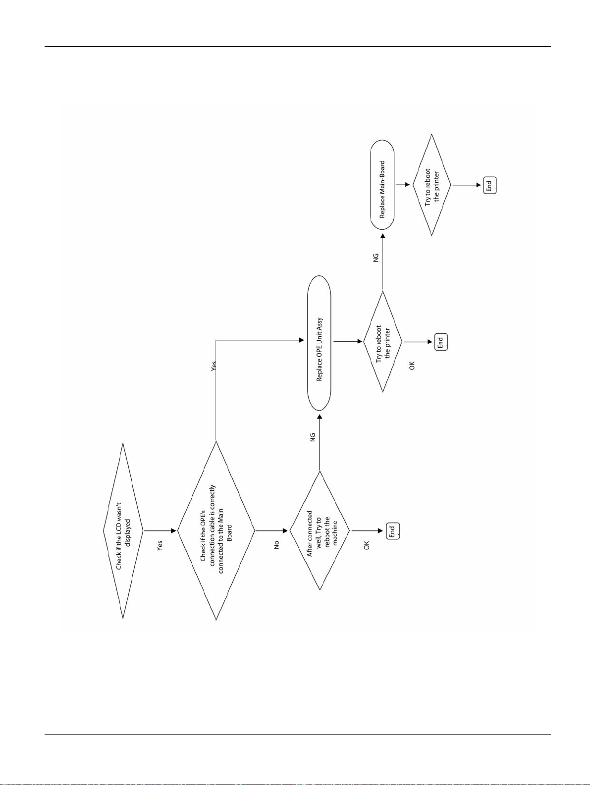
RAP 3 Nothing Displayed on LCD
Figure 1
2-6 5/08 Phaser 3435
Page 27
Status Indicator RAPs
RAP 4 Paper Jams
Clearing Paper Jams
Message Location of Jam
Paper Jam 0 Open/Close Door In the paper feed area (tray 1, optional tray 2, multi-purpose tray)
Paper Jam 1 Around the print cartridge
Open/Close Door Paper Jam 2 Check Inside In the paper exit area
Duplex Jam 0 Check Inside In the duplex area
Duplex Jam 1 Open/Close Door Between the duplex unit and fuser area
Jams in the Paper Feed Area
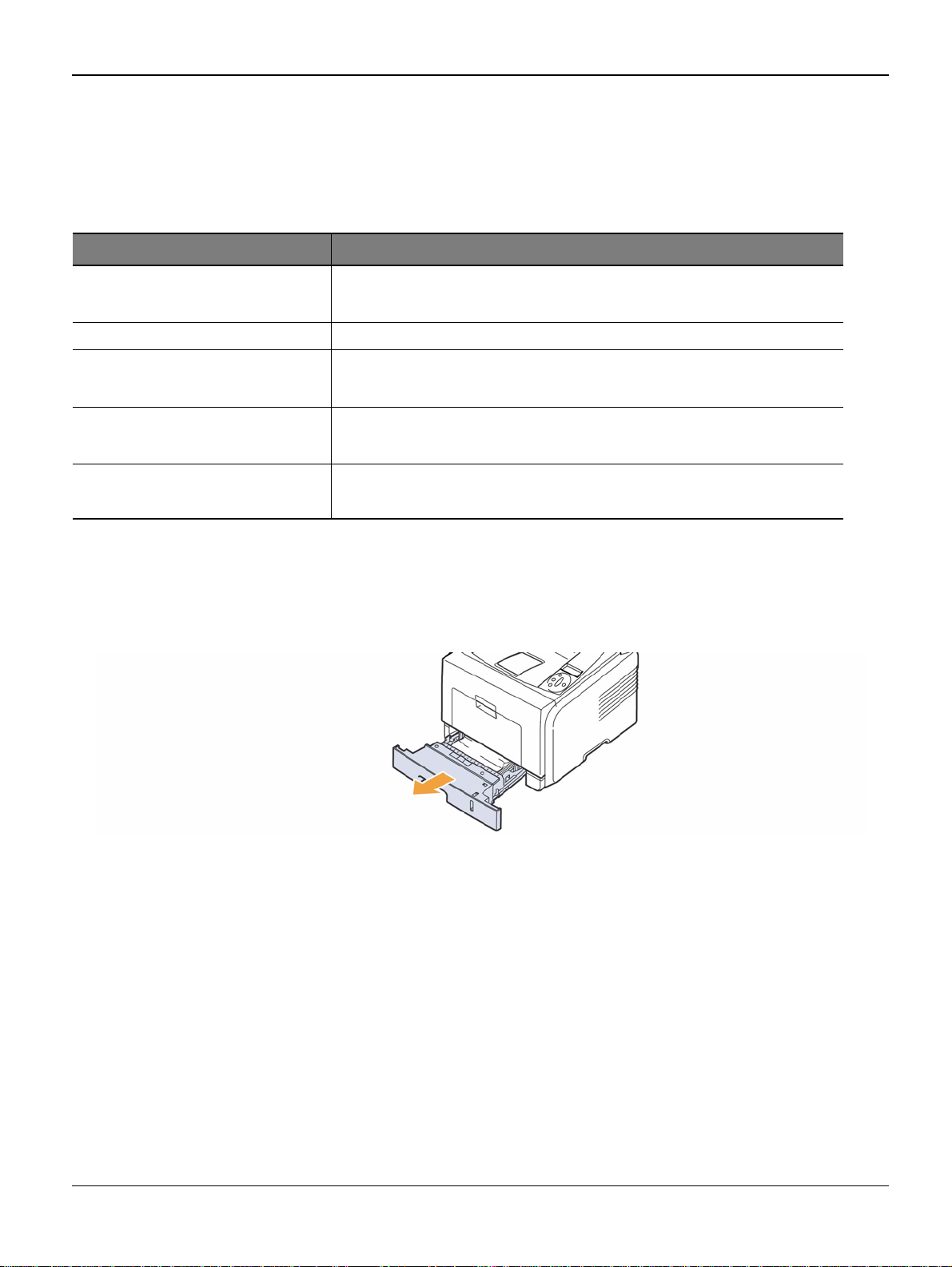
In the Tray
1. Pull the tray 1
Figure 1
Phaser 3435 5/08 2-7
Page 28

Status Indicator RAPs
2. Remove the j ammed paper by gently pulling it straight out. Make sure that all of the paper is
properly aligned in the tray 1.
Figure 2
If the paper is not move when you pull, or if you do not see the paper in this area, check the
fuser area around the print cartridge.
3. Insert the tray 1 into the printer until it snaps into place. Printing automatically resumes.
In the Optional Tray 2
1. Pull the optional tray 2 open.
2. Remove the j ammed paper from the printer.
Figure 3
If the paper is not m ove when you pull, or if you do not see the p aper i n this are a, stop and go
to step 3.
3. Pull the tray 1 half.
4. Pull the paper straight up and out.
2-8 5/08 Phaser 3435
Page 29
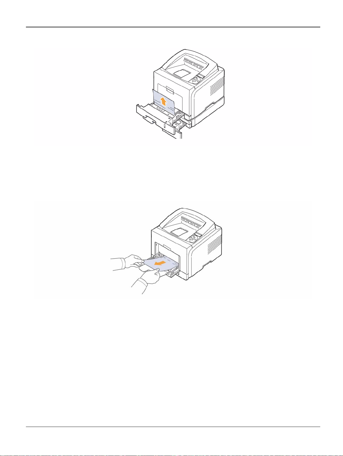
Figure 4
5. Insert the trays back into the printer. Printing au tomatically resumes.
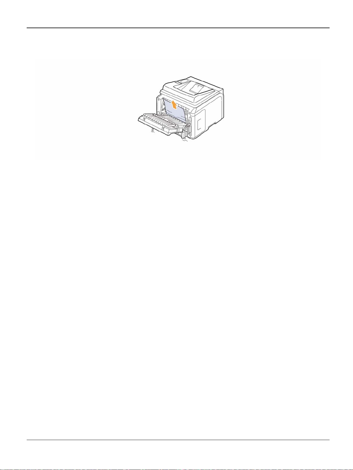
In the Multi-Purpose Tray
1. If the paper is not feeding properly, pull the paper out of the printer.
Status Indicator RAPs
Figure 5
2. Open and close the front cover to resume printing.
Around the Print Cartridge
1. Open the front cover and pull the print cartridge out.
Phaser 3435 5/08 2-9
Page 30

Status Indicator RAPs
Figure 1
2. Remove the j ammed paper by gently pulling it straight out.
Figure 2
3. Replace th e print cartridge and close the front cover. Print ing automatically resumes.
In the Paper Exit Area
1. Open and close the front cover. The jammed paper is automatically ejected from the printer.
2. Gently pull the paper out of the output tray.
2-10 5/08 Phaser 3435
Page 31

Status Indicator RAPs
Figure 1
If you do not see the jammed paper or if there is any resistance when you pull, stop and go to
the next step.
3. Open the rear cover.
4. If you see the ja mmed paper, push the pressure lever on each side up a nd remove the paper.
Return the pressure lever to its original position.
Figure 2
If you still do not see the paper, go to the next step.
5. Release the blue strap, the rear cover stopper, and full y open the rear c over, as shown.
Phaser 3435 5/08 2-11
Page 32

Status Indicator RAPs
6. Unfold the duplex guide full y.
Figure 3
Figure 4
7. While pushing the fuser lever to the right, open the fuser door.
2-12 5/08 Phaser 3435
Page 33

Status Indicator RAPs
Figure 5
8. Pull the jammed paper out.
If the jammed paper does not move when you pull, push the pressure lever on each side up
to loose the paper, and then remove it.
Figure 6
1
9. Return the lever, door, stopper, and guide to their original position.
10.Close the rear cover. Printing automatically resumes.
In the Duplex Unit Area
If the duplex unit is not inserted correctly, pa per jam ma y occur. Make sure that the du plex unit is
inserted correctly.
Duplex jam 0
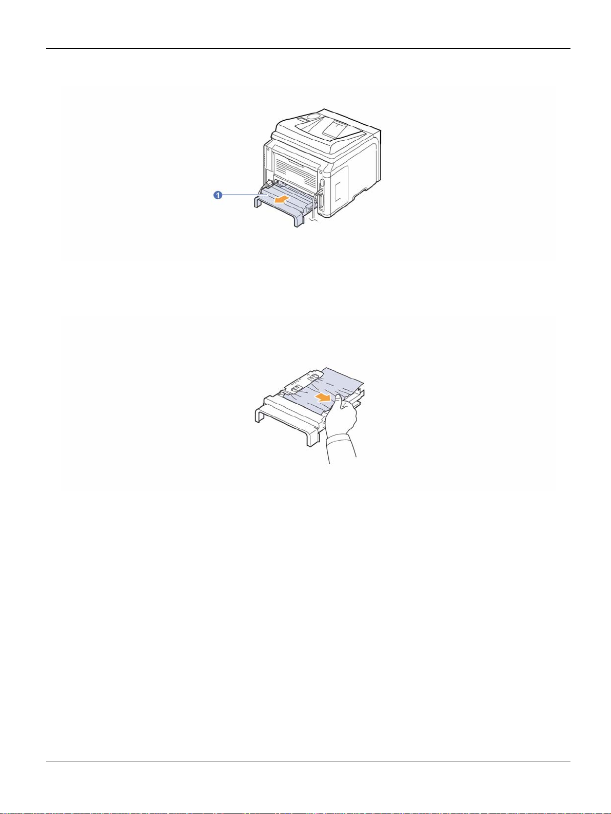
1. Pull the duplex unit out of the printer.
Phaser 3435 5/08 2-13
Page 34
Status Indicator RAPs
Figure 1
2. Remove the jammed paper from the duplex unit.
Figure 2
If the paper does not come ou t with the duplex un it, remove the paper fro m the bottom of the pr inter.
2-14 5/08 Phaser 3435
Page 35

Duplex jam 1
1. Open the rear cover.
2. Unfold the duplex guide full y.
Status Indicator RAPs
Figure 3
Figure 4
Phaser 3435 5/08 2-15
Page 36
Status Indicator RAPs
3. Pull the jammed paper out.
Figure 5
2-16 5/08 Phaser 3435
Page 37
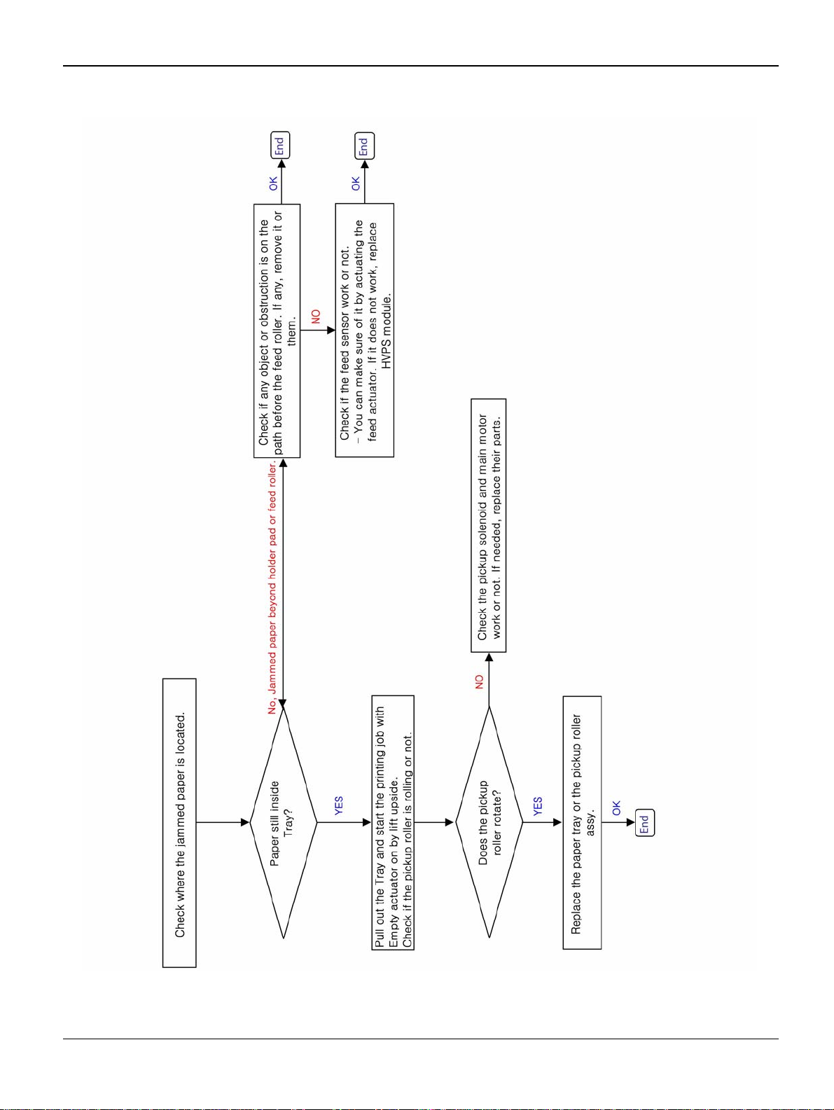
RAP 5 JAM 0
1. Paper is not exited from the cassette.
2. Jam-0 occurs when the paper feeds into the printer.
Status Indicator RAPs
Figure 1
Phaser 3435 5/08 2-17
Page 38
Status Indicator RAPs
Figure 2
2-18 5/08 Phaser 3435
Page 39

Status Indicator RAPs
RAP 6 JAM 1
Description
1. Paper is jammed in front of or inside the fuser.
2. Paper is stuck in the discharge roller and in the fuser just after passing through the feed sensor actuator.
Figure 1
Phaser 3435 5/08 2-19
Page 40

Status Indicator RAPs
Figure 2
2-20 5/08 Phaser 3435
Page 41

Status Indicator RAPs
RAP 7 JAM 2
Description
1. Paper is jammed in front of or inside the fuser.
2. Paper is stuck in the discharge roller and in the fuser just after passing through the ActuatorFeed.
Figure 1
Phaser 3435 5/08 2-21
Page 42
Status Indicator RAPs
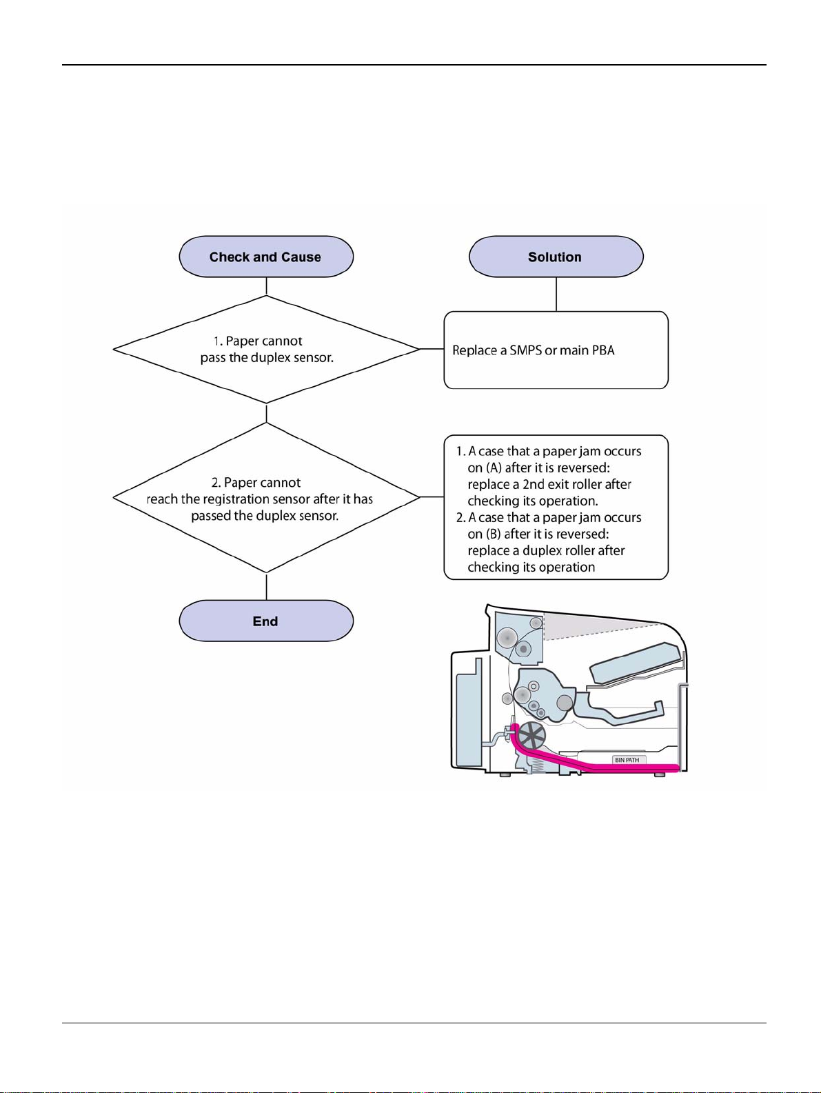
RAP 8 JAM Duplex 1
Description
A message “Jam Duplex 1” is displayed in a LCD window.
Figure 1
2-22 5/08 Phaser 3435
Page 43

RAP 9 JAM Duplex 2
Description
A message “Jam Duplex 2” is displayed in a LCD window.
Status Indicator RAPs
Figure 1
Phaser 3435 5/08 2-23
Page 44

Status Indicator RAPs
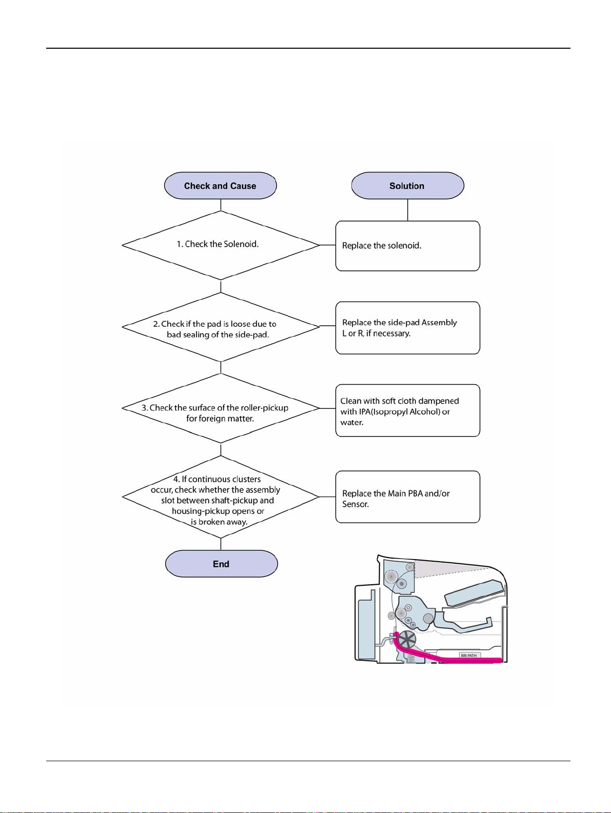
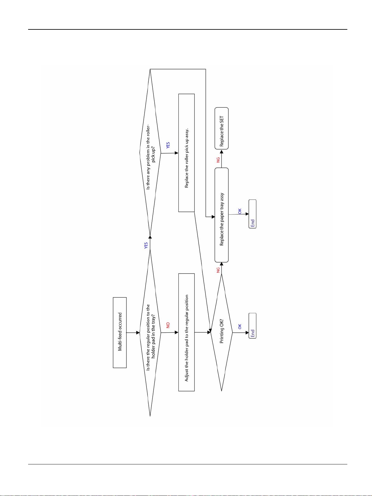
RAP 10 Multi-Feeding
Description
Multiple sheets of paper are fed at once.
Figure 1
2-24 5/08 Phaser 3435
Page 45
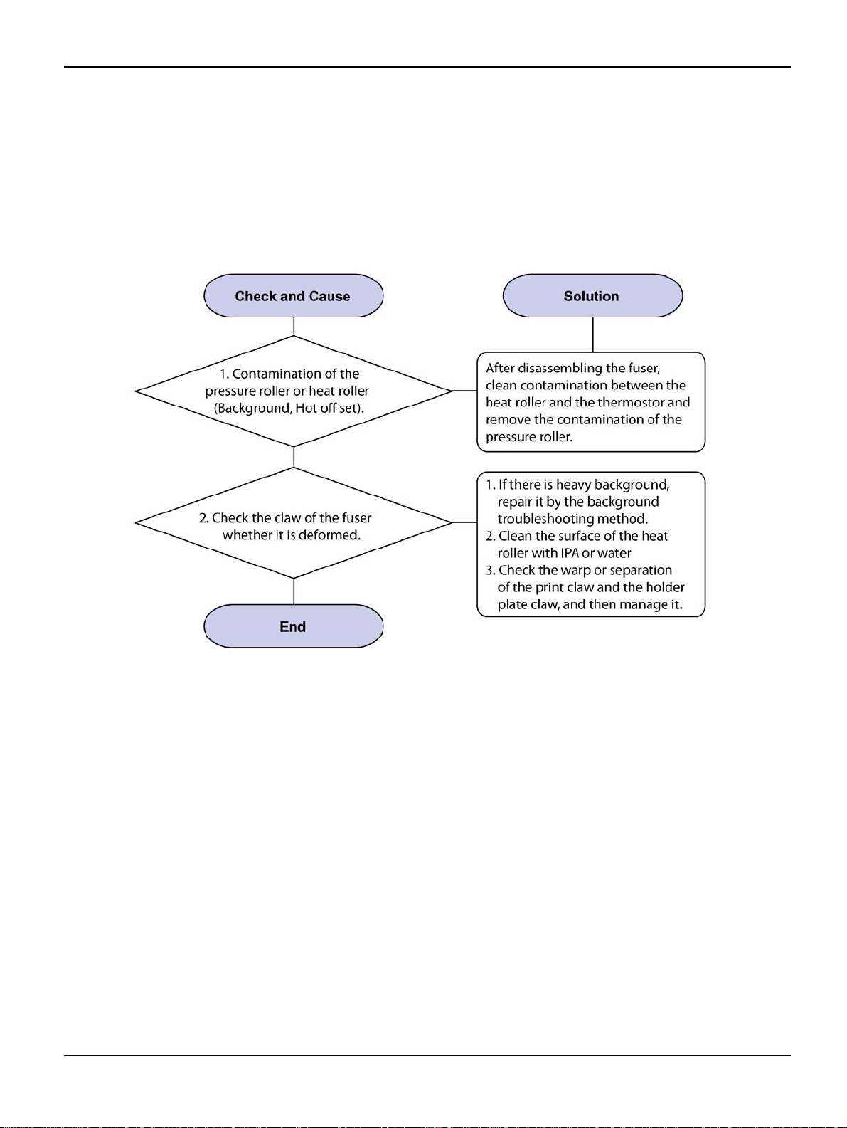
RAP 11 Paper Rolled in the Fuser
Description
Paper is jammed in the fuser.
Status Indicator RAPs
Figure 1
Phaser 3435 5/08 2-25
Page 46
Status Indicator RAPs
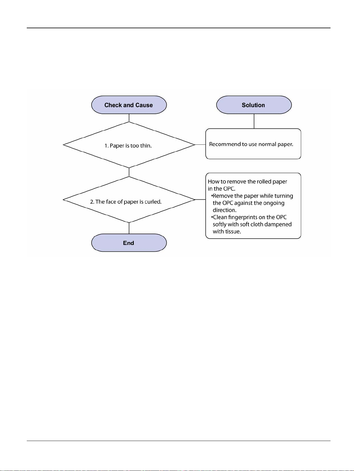
RAP 12 Paper Rolled on the OPC Drum
Description
Paper is rolled up in the OPC.
Figure 1
2-26 5/08 Phaser 3435
Page 47
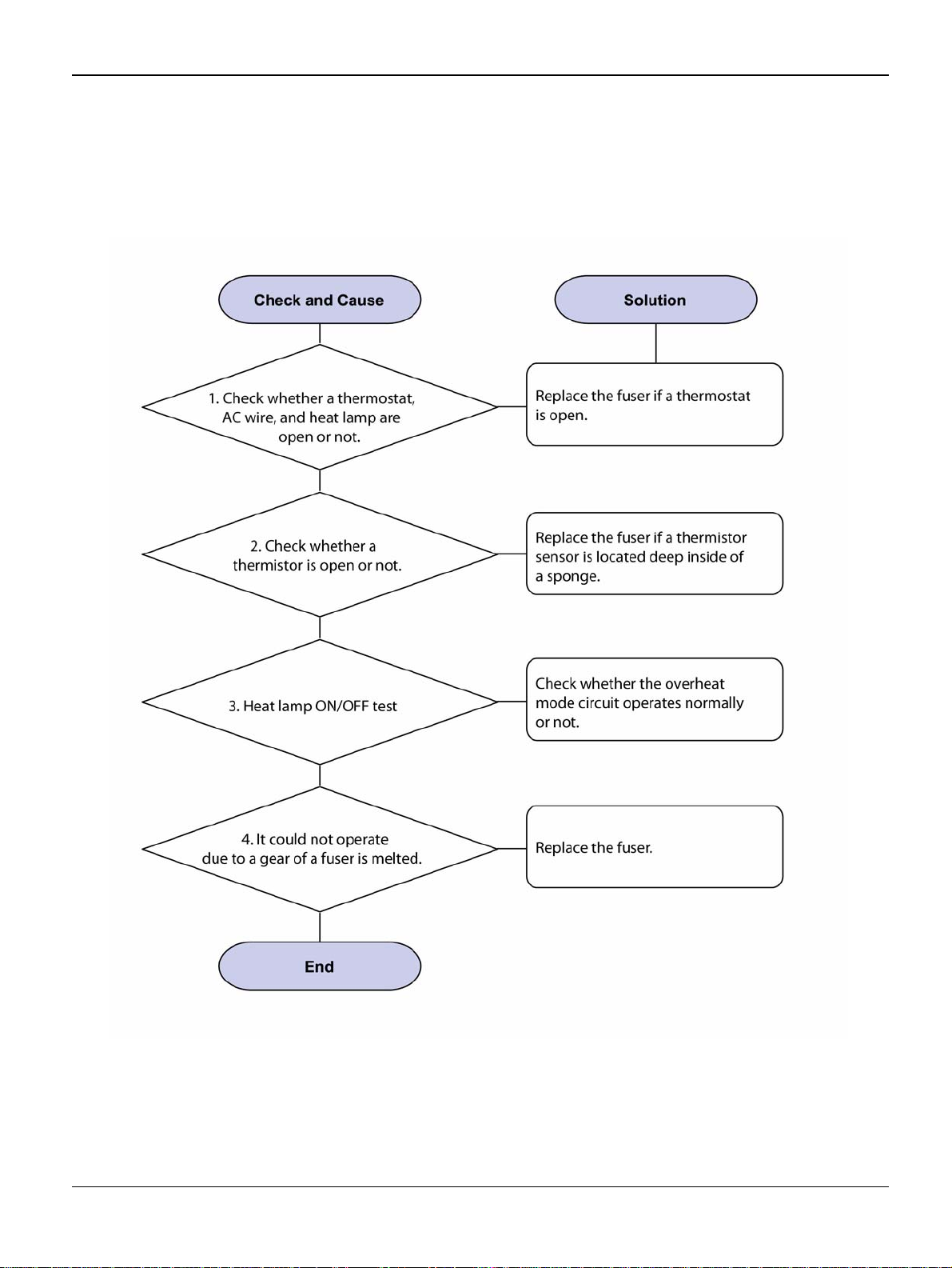
RAP 13 Fuser Error
Description
A message “Ope n fuser/Over he at/Low heat” is di splace in a LCD panel.
Status Indicator RAPs
Figure 1
Phaser 3435 5/08 2-27
Page 48

Status Indicator RAPs
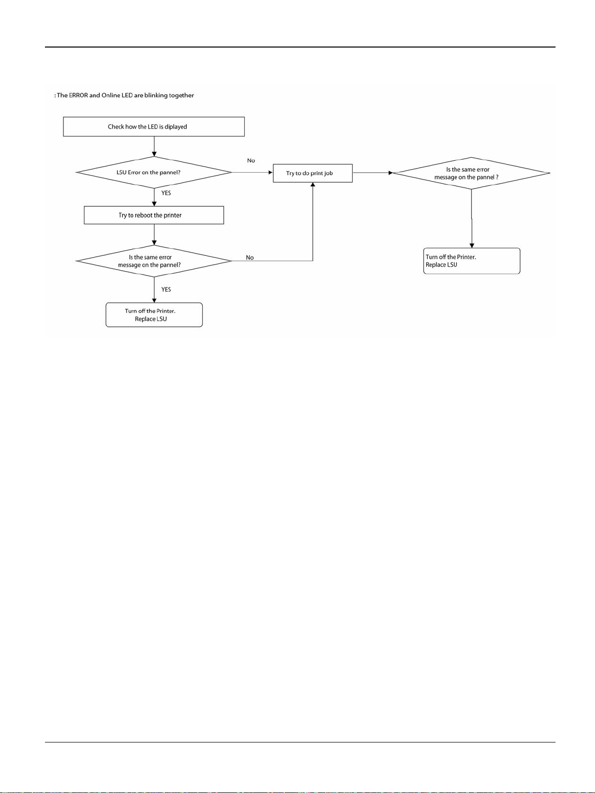
RAP 14 LSU Error
Description
A message “PMOTOR ERROR/HSYNC ERROR” is disp layed in a LCD panel.
Figure 1
2-28 5/08 Phaser 3435
Page 49
Status Indicator RAPs
Figure 2
Phaser 3435 5/08 2-29
Page 50

Status Indicator RAPs
RAP 15 Fuser Drive Gear Damage
Description
The motor breaks away from its place due to gear melting away.
Figure 1
2-30 5/08 Phaser 3435
Page 51
Status Indicator RAPs
RAP 16 Paper Empty
Description
The paper lamp on the operator panel is on even when paper is loaded in the cassette.
Figure 1
Phaser 3435 5/08 2-31
Page 52

Status Indicator RAPs
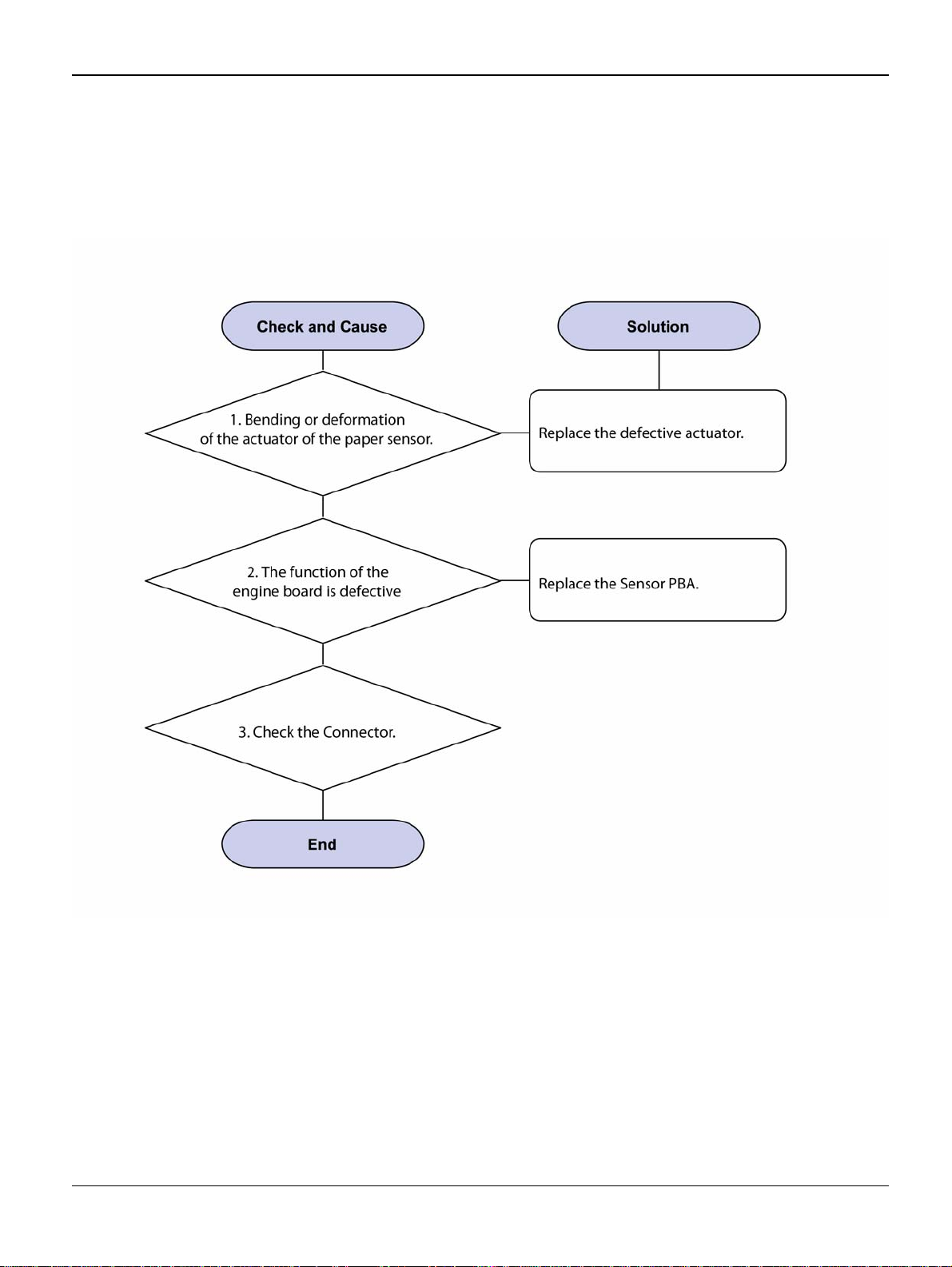
RAP 17 Paper Empty Without Indication
Description
The paper lamp on the operator panel does not come on when the paper cassette is empty.
Figure 1
2-32 5/08 Phaser 3435
Page 53

RAP 18 Cover Open
Description
The ERROR lamp is on even when the print cover is closed.
Status Indicator RAPs
Figure 1
Phaser 3435 5/08 2-33
Page 54
Status Indicator RAPs
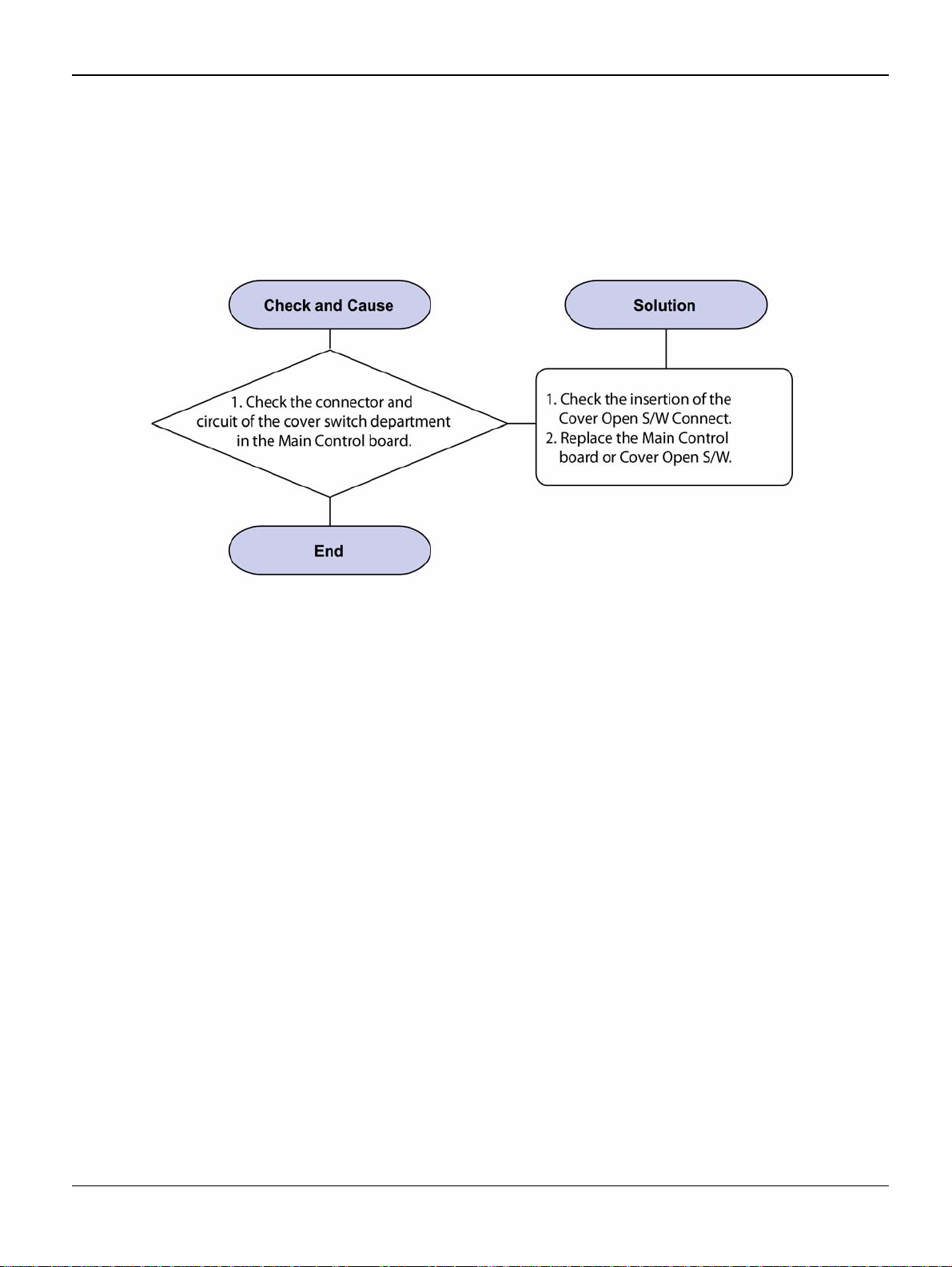
RAP 19 No Error Message When the Cover is Open
Description
The ERROR message does not come on even when the printer cover is open.
Figure 1
2-34 5/08 Phaser 3435
Page 55

Status Indicator RAPs
RAP 20 Defective Motor Operation
Description
Main motor is not driving when printing and paper does not feed into the printer.
Figure 1
Phaser 3435 5/08 2-35
Page 56
Status Indicator RAPs
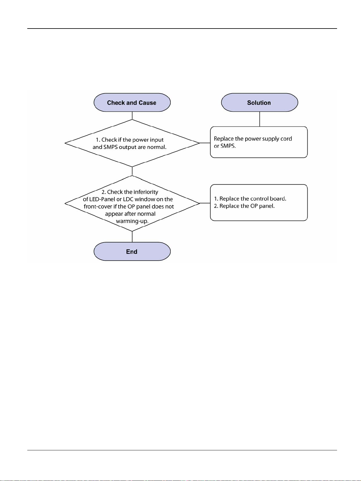
RAP 21 No Power
Description
When system power is turned on, all lamps on the operator panel do not come on.
Figure 1
2-36 5/08 Phaser 3435
Page 57

RAP 22 Printer Not Working (1)
Description
While Power turned on, the printer is not work ing in the printing mode.
Status Indicator RAPs
Figure 1
Phaser 3435 5/08 2-37
Page 58

Status Indicator RAPs
RAP 23 Printer Not Working (2)
Description
After receiving the printing order, no response at all or the low speed of printing occurs due to
wrong setup of the environment rather than malfunction of the printer itself.
Figure 1
2-38 5/08 Phaser 3435
Page 59

Status Indicator RAPs
RAP 24 Abnormal Printing
Description
The printer is not working properly even when the cable has no prob lem (even after the cable is
replaced).
If the printer won’t wor k at all or th e strange f onts are repeat ed, the prin ter driver may be defective
or setup in the CMOS Setup.
Figure 1
Phaser 3435 5/08 2-39
Page 60
Status Indicator RAPs
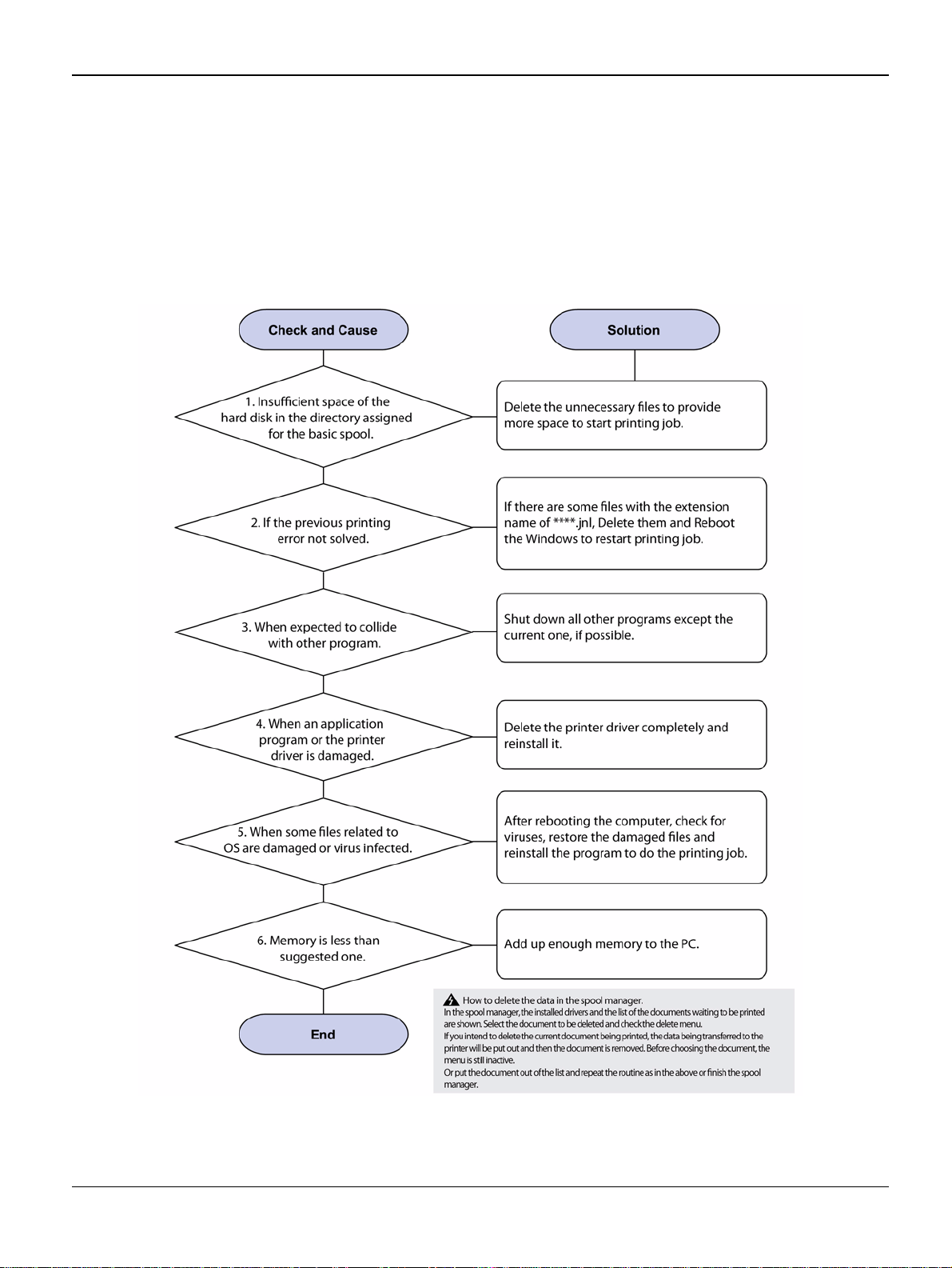
RAP 25 SPOOL Error
Description
To spool which stands for "simultaneous peripheral operations online" a computer document or
task list (or "job") is to read it and sto re it, usuall y on a hard di sk or larger storage medi um so that
it can be printed or otherwise processed at a more convenient time (for example, when a printer
is finished printing its current d oc ument).
Figure 1
2-40 5/08 Phaser 3435
Page 61
RAP 26 Multi-Feed Error
Status Indicator RAPs
Figure 1
Phaser 3435 5/08 2-41
Page 62

Status Indicator RAPs
RAP 27 No Paper/Add Paper Error
Figure 1
2-42 5/08 Phaser 3435
Page 63

RAP 28 Open Cover Error
Status Indicator RAPs
Figure 1
Phaser 3435 5/08 2-43
Page 64

Status Indicator RAPs
RAP 29 Fuser Door Open
Figure 1
2-44 5/08 Phaser 3435
Page 65

RAP 30 Audible Noise
Status Indicator RAPs
Figure 1
Phaser 3435 5/08 2-45
Page 66

Status Indicator RAPs
RAP 31 Scan Lock Error
Figure 1
2-46 5/08 Phaser 3435
Page 67

Image Quality
3 Image Quality
IQ 1 Test Patterns .................................................................................................................... 3-3
IQ 2 Abnormal Image Printing and Defective Roller ................................................................. 3-5
IQ 3 Vertical Black Line and Band ................... ..... ..... ............................ .... ..... .......................... 3-6
IQ 4 Vertical White Line ............................................................................................................ 3-7
IQ 5 Horizontal Black Band ...................................................................................................... 3-8
IQ 6 Black/White Spot .............................................................................................................. 3-9
IQ 7 Light Image ..................................................................................................................... 3-10
IQ 8 Dark Image or a Black Page ........................................................................................... 3-11
IQ 9 Uneven Density .............................................................................................................. 3-12
IQ 10 Background .................................................................................................................. 3-13
IQ 11 Ghost (1) ....................................................................................................................... 3-14
IQ 12 Ghost (2) ....................................................................................................................... 3-16
IQ 13 Ghost (3): Fuser ........................................................................................................... 3-17
IQ 14 Stains on the Face of Page .......................................................................................... 3-18
IQ 15 Stains on Back of Page ................................................................................................ 3-19
IQ 16 Blank Page Print Out (1) ............................................................................................... 3-20
IQ 17 Blank Page Print Out (2) ............................................................................................... 3-21
IQ 18 Wrong Print Position ..................................................................................................... 3-22
IQ 19 Curved Vertical Line ..................................................................................................... 3-23
IQ 20 Signs and Measures of Poor Toner Cartridge .............................................................. 3-24
IQ 21 Low Toner ..................................................................................................................... 3-27
Phaser 3435 5/08 3-1
Page 68

Image Quality
This page is intentionally blank
3-2 5/08 Phaser 3435
Page 69
Image Quality
IQ 1 Test Patterns
This product has the several sample patterns for maintenance. With the sample patterns, check
the existence of the abnormal ity. The patterns help to regularly mainta i n the product.
Printing a Demo Page
Print a demo page or a configuration sheet to make sure that the printer is operating correctly.
Press the Menu button to select (Information -> Demo Page).
Figure 1
Phaser 3435 5/08 3-3
Page 70

Image Quality
Sample Tests Patterns
The sample patterns shown below are the standard test patterns u sed in the factory.The life of the
print cartridge, d eveloper cartridge and printing speed are meas ured with the pattern show n below
(5%). The A4 ISO 197 52 stan dard patte rn samp les are repro duced re duced to 70% of the actual
A4size.
Figure 2
3-4 5/08 Phaser 3435
Page 71

IQ 2 Abnormal Image Printing and Defective Roller
If abnormal image prints periodically, check the parts shown below.
Image Quality
Figure 1
No Roller Abnormal imag e period Kind of abnormal image
1 OPC Drum 75.5mm White spot, Block spot
2 Charge Roller 37.7mm Black spot
3 Supply Roller 44.9mm Horizontal density band
4 Develop Roller 35.2mm Horizontal density band
5 Transfer Roller 47.1mm Black side contamination/transfer fault
6 Heat Roller 77.8mm Black spot and fuser ghost
7 Pressure Roller 62.8mm / 50.24mm Black side contamination
Phaser 3435 5/08 3-5
Page 72
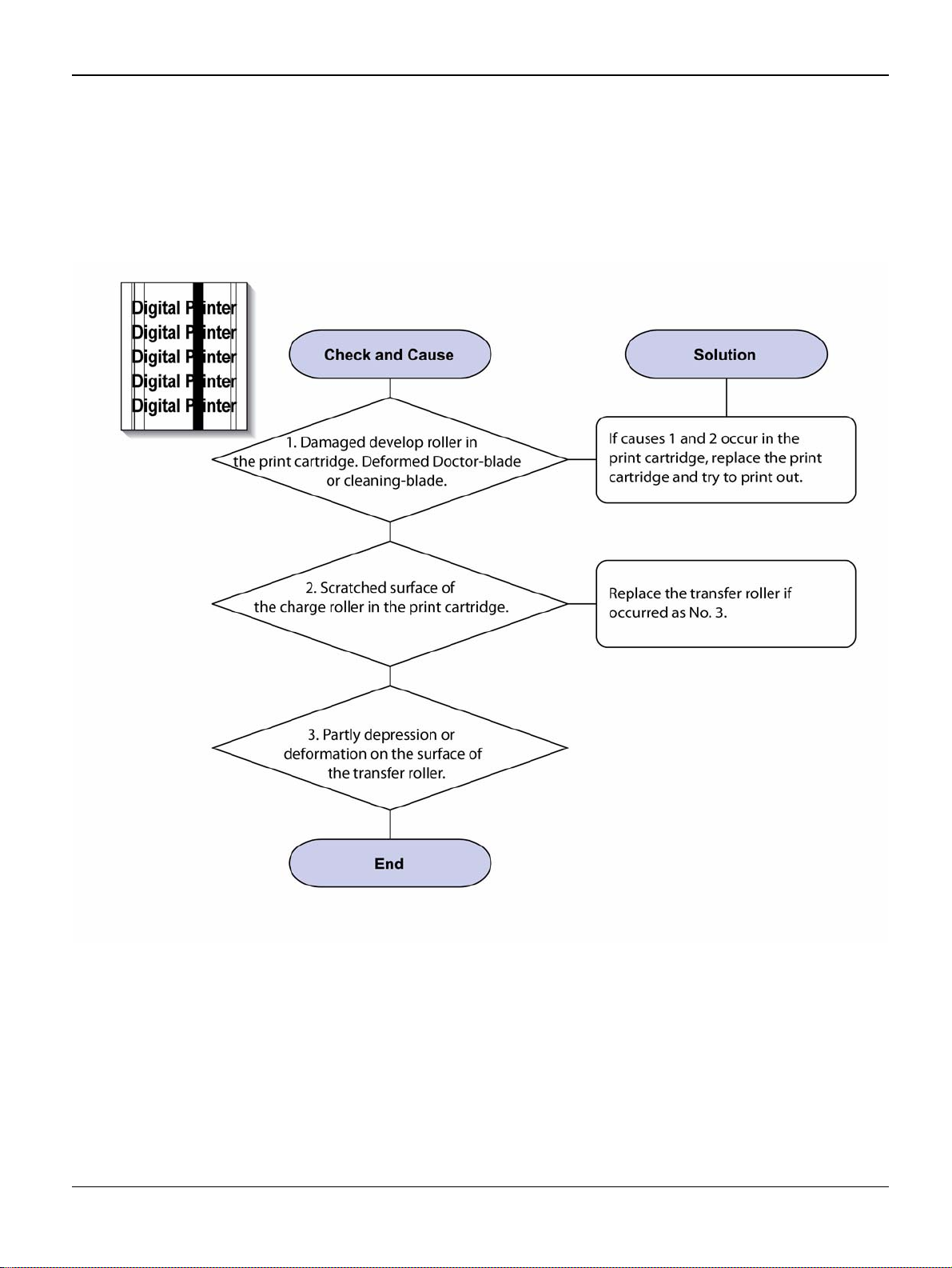
Image Quality
IQ 3 Vertical Black Line and Band
Description
1. Straight t hin black vertical line occurs in the printing.
2. Dark black vertical band occur in the printing.
Figure 1
3-6 5/08 Phaser 3435
Page 73
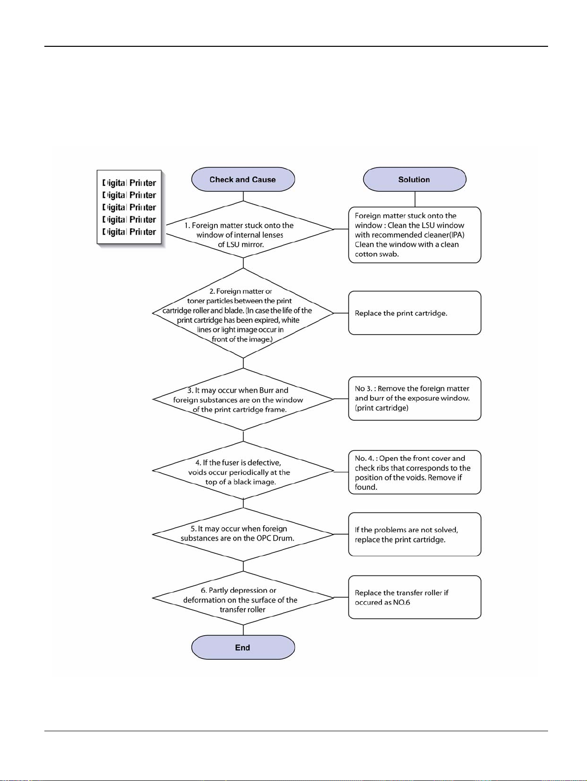
IQ 4 Vertical White Line
Description
White vertical voids in the image.
Image Quality
Figure 1
Phaser 3435 5/08 3-7
Page 74

Image Quality
IQ 5 Horizontal Black Band
Description
Dark or blurry horizontal stripes occur in the printing.
Figure 1
3-8 5/08 Phaser 3435
Page 75

IQ 6 Black/White Spot
Description
1. Dark or blurry spots occur periodically in the printing
2. White spots occur periodically in the printing.
Image Quality
Figure 1
Phaser 3435 5/08 3-9
Page 76
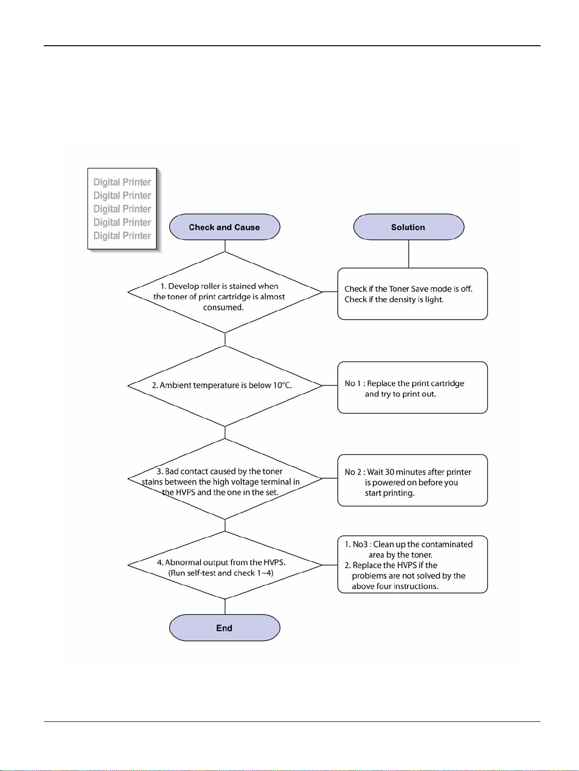
Image Quality
IQ 7 Light Image
Description
The printed image is light, with no ghost.
Figure 1
3-10 5/08 Phaser 3435
Page 77

IQ 8 Dark Image or a Black Page
Description
The printed imag e is dark.
Image Quality
Figure 1
Phaser 3435 5/08 3-11
Page 78

Image Quality
IQ 9 Uneven Density
Description
Print density is uneven between left and right.
Figure 1
3-12 5/08 Phaser 3435
Page 79

IQ 10 Background
Description
Light dark background appears in whole area of the printing.
Image Quality
Figure 1
Phaser 3435 5/08 3-13
Page 80

Image Quality
IQ 11 Ghost (1)
Description
Ghost occurs at 95 mm intervals of the OPC drum in the whole printing.
Figure 1
3-14 5/08 Phaser 3435
Page 81

Figure 2
Image Quality
Phaser 3435 5/08 3-15
Page 82

Image Quality
IQ 12 Ghost (2)
Description
Ghost occurs at 95 mm intervals of the OPC drum in the whole printing. (When printing on card
stock or transparencies using manual feeder)
Figure 1
3-16 5/08 Phaser 3435
Page 83
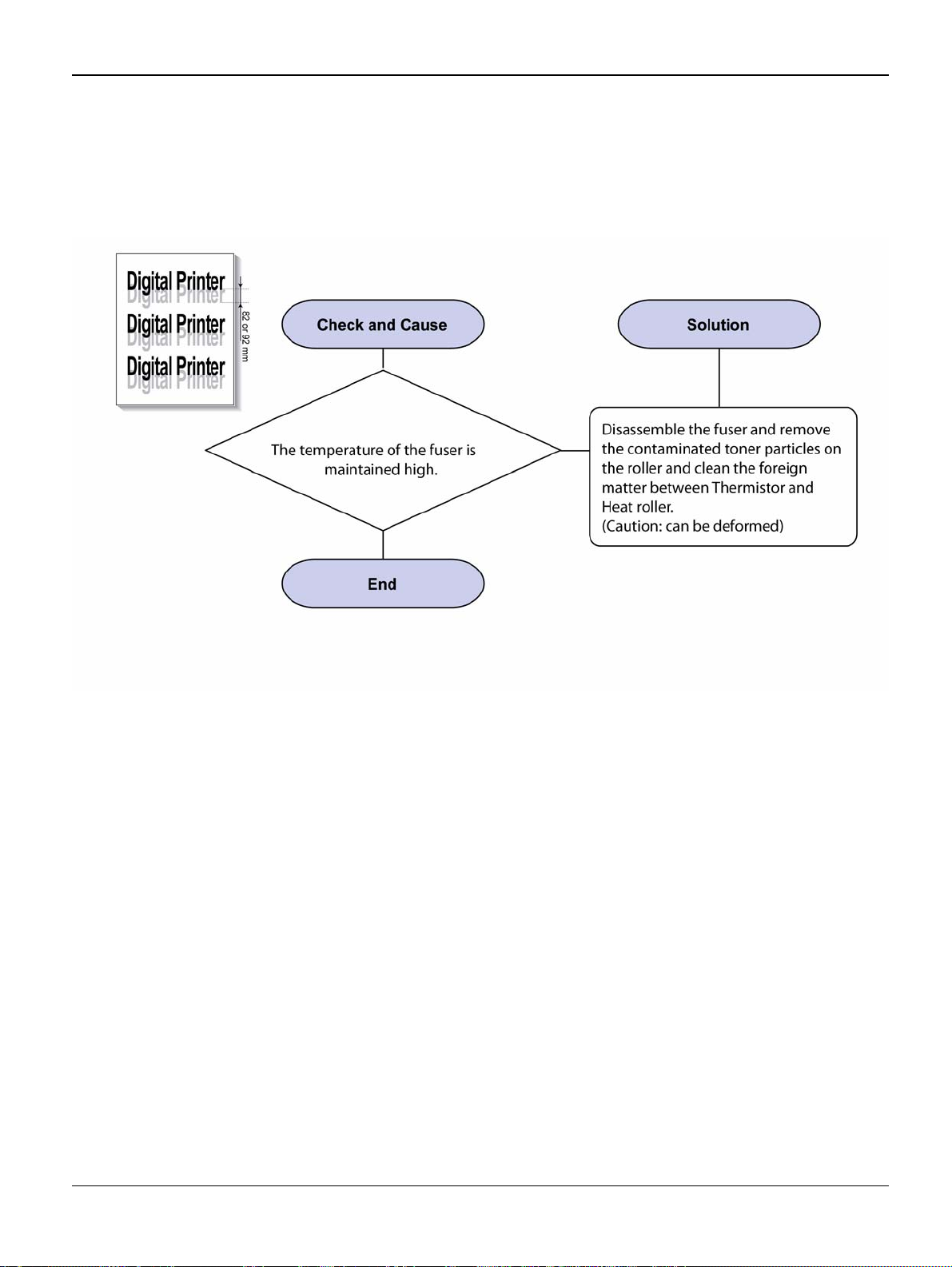
IQ 13 Ghost (3): Fuser
Description
Ghost occurs at 82 or 92 mm intervals.
Image Quality
Figure 1
Phaser 3435 5/08 3-17
Page 84

Image Quality
IQ 14 Stains on the Face of Page
Description
The background on the face of the printed page is stained.
Figure 1
3-18 5/08 Phaser 3435
Page 85

IQ 15 Stains on Back of Page
Description
The back of the page is stained at 57 or 92 mm intervals.
Image Quality
Figure 1
Phaser 3435 5/08 3-19
Page 86

Image Quality
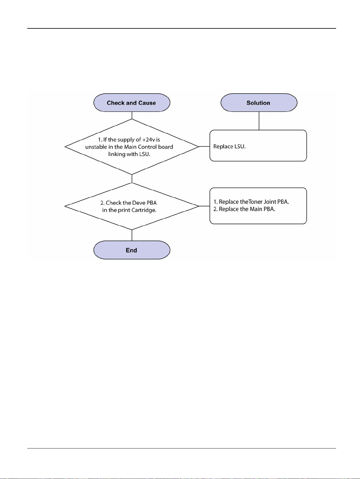
IQ 16 Blank Page Print Out (1)
Description
Blank page is printed.
Figure 1
3-20 5/08 Phaser 3435
Page 87

IQ 17 Blank Page Print Out (2)
Description
1. Blank page is printed.
2. One or several blank pages are printed
3. When the printer turns on, several blank pages print.
Image Quality
Figure 1
Phaser 3435 5/08 3-21
Page 88

Image Quality
IQ 18 Wrong Print Position
Description
Printing begins at wrong position on the paper.
3-22 5/08 Phaser 3435
Page 89
IQ 19 Curved Vertical Line
Description
When printing, vertical line get curved.
Image Quality
Figure 1
Phaser 3435 5/08 3-23
Page 90

Image Quality
IQ 20 Signs and Measures of Poor Print Cartridge
Table 1:
Fault Signs Cause & Check Solution
Light image and partially blank image
(The life is ended.)
• The printed image
is light or unclean
and untidy.
• Some part of the
image is not printed.
• Periodically a noise
as "tick tick" occurs.
1. If the image is light or
unclean and untidy printed
image -Shake the print cartridge and then recheck.
(1)NG: Check the weight of
the print cartridge
(2)OK: Lack of toner, so the
life is nearly closed.
2. Some part of image is not
printed -Shake the print cartridge and then recheck.
(1)NG: Check the weight of
the print cartridge and clean
the LSU window with a cotton
swab, then recheck.
(2)OK: Lack of toner, so the
life is nearly closed.
3. Periodically a noise as "tick
tick" occurs - Measure the
cycle and the weight of the
print cartridge.
4. White vertical stripes on the
whole screen or partly: Check
the weight of the print cartridge.
1. All of 1, 2, 3 above-If it
become better by shaking,
replace with a new print cartridge after 50-100 sheets in the
closing state of the life span.
2. In case of 2-If it becomes better after cleaning the LSU window, then the print cartridge is
normal. (Because of foreign
substance on the LSU window,
the image has not been printed
partly.)
3. In case of 3-If the cycle of
noise is about 2 seconds, the
toner inside the print cartridge
has been nearly exhausted.
(Purchase and replace with a
new print cartridge after using
about 200 sheets at the point of
occurrence)
4. In case of 3-This is a phenomenon caused by lack of
toner, so replace with a new
print cartridge.
Toner Contamination
3-24 5/08 Phaser 3435
• Toner is fallen on
the papers periodically.
• Contaminated with
toner on prints partly
or over the whole
surface.
1. Toner is fall en on th e paper
periodically.
(1)Check the cycle of the falling of the toner.
(2)Check the appearance of
both ends of the print cartridge OPC drum.
2.The centre of the printed
matter is contaminated with
toner.
(1)Check whether foreign
substances or toner are stuck
to the terminal (contact point)
of the print cartridge.
(2)Check whether the state of
the terminal assembly is normal.
1. If both ends of the OPC drum
are contaminated with toner:
Check the life of the print cartridge.
2. Check whether it could be
recycled.
3. If it cannot be recycled:
Replace the print cartridge.
Page 91

Image Quality
Table 1:
Fault Signs Cause & Check Solution
White Black spot • Light or dark black
dots on the image
occur periodically. •
White spots occur in
the image periodically.
1. If light or dark periodical
black dots occur, this is
because the print cartridge
rollers are contaminated with
foreign substance or paper
particles.
(1)38mm interval: Charge d
roller
(2)95mm interval: OPC cycle
2. If white spots occur in a
black image at intervals of
95mm, or black spots occur
elsewhere, the OPC drum is
damaged or foreign substance is stuck to the surface.
3. If a black and white or
graphic image is partially broken at irregular intervals, the
transfer roller's life has been
expired or the transfer voltage
is abnormal.
1. In case of 1 above -Run OPC
Cleaning Mode Print 4-5 times
repeatedly to remove, refer to
GP 5
. Especially check foreign
substance on the OPC surface,
then remove them with a clean
gauze moistened with IPA (Isopropyl Alcohol) not to damage
OPC if necessary. Never use
usual alcohol.
2. In case of 2 If they are not
disappeared by running OPC
Cleaning Mode Print 4-5 times.:
at intervals of 38mm -Replace
the print cartridge.: at intervals
of 95mm - Remove foreign substance.: Broken image -Replace
the print cartridge according to
carelessness.
3. In case of 3 -Exchange the
transfer roller because the life of
the transfer roller in use has
been expired. (Check the transfer voltage and readjust if different.)
Recycled product • Poor appearance
of the print cartridge.
• Unclean and rough
printouts. • Bad
background in the
image.
1. Poor appearance of the
print cartridge.
(1)Check the damage to label
and whether different materials are used .
(2)Check the appearance of
parts of the print cartridge,
such as frame, hopper.
2. Unclean and rough printouts.
(1)Check whether foreign
substance or toner are stuck
to the terminal (contact point)
of the print cartridge.
(2)Check whether the state of
the terminal assembly is normal.
1. In case of 1
(1)If there is an evidence of disassembling the print cart ridge .
(2)If materials other than normal
parts of the print cartridge are
added or substituted.
2. In case of 2 -If there are any
abnormality in connection with
the situation of 1.
(1)It occurs when the print cartridge is recycled over 2 times.
(2)If toner nearly being expired
are collected to use, it is judged
as the recycled print cartridge.
Phaser 3435 5/08 3-25
Page 92

Image Quality
Fault Signs Cause & Check Solution
Table 1:
Ghost & Image Contamination
• The printed image
is too light or dark, or
partially contaminated black. • Totally
contaminated black.
(Black image printed
out) • The density of
printouts is too dark
and ghost occurs.
1. The printed image is too
light or dark, or partially contaminated black.
(1)Check whether foreign
substance or toner are stuck
to the terminal (point of contact) of the print cartridge.
(2)Check whether the terminal
assembly is normal.
2. Totally contaminated black.
(Black image printed out)
(1)Check whether foreign
substances are stuck to the
terminal (point of contact) of
the print cartridge and the
state of assembly. (Especially check the charged roller
terminal.)
3. The printed image is dark
and ghost occurs.
(1)Check foreign substance
attached to the terminal (point
of contact) of the print cartridge and the state of assembly. (Especially check the
developing roller terminal.)
1. All of 1, 2, 3 above
(1)Remove toner and foreign
substances adhered to the contact point of the print cartridge.
(2)The contact point of the unit
facing that of the print cartridge
also must be cleaned.
(3)If the terminal assembly is
unsafe: • Fully stick the terminal
to or reassemble it after disassembling. • Disassemble the
side plate and push the terminal
to be stuck, then reassemble it.
2. In case of 2 It is a phenomenon when the OPC drum of the
print cartridge is not electrically
charged. Clean the terminals of
the charged roller, then recheck
it.
3. In case of 3 It is a phenomenon as the developing bias voltage of the print cartridge. Clean
the terminals of the developing
roller, then recheck it.
3-26 5/08 Phaser 3435
Page 93

IQ 21 Low Toner
Image Quality
Figure 1
Phaser 3435 5/08 3-27
Page 94

Image Quality
This page is intentionally blank
3-28 5/08 Phaser 3435
Page 95

Repairs and Adjustments
4 Repairs and Adjustments
REP 1 Front Cover ........................ ............................ .... ..... ..... ............................ .... ..... ............ 4-3
REP 2 MP Tray Assembly ....................................................................................................... 4-6
REP 3 Rear Cover ................................................................................................................... 4-8
REP 4 Fuser Assembly ......................................................................................................... 4-11
REP 5 Top Cover ............................................................................ ..... .... ............................. 4-17
REP 6 OPE Unit .................................................................................................................... 4-19
REP 7 Side Cover (Left, Right) ............................................................................................. 4-21
REP 8 Shield Controller Assembly ........................................................................................ 4-25
REP 9 Drive Assembly ..................... ..... ..... ............................ .... ..... ..... ............................ ..... 4-28
REP 10 Duplex Drive Assembly ............................................................................................ 4-30
REP 11 Shield SMPS Assembly ........................................................................................... 4-32
REP 12 Connection PCB ...................................................................................................... 4-34
REP 13 Fuser Drive Assembly ............................................................................................... 4-36
REP 14 Fans .......................................................................................................................... 4-38
REP 15 Pick-up Roller Assembly ........................................................................................... 4-40
REP 16 Duplex Guide Housing (With Feed Roller) ................................................................ 4-42
REP 17 HVPS Housing ......................................................................................................... 4-44
REP 18 Cover Mid Front ....................................................................................................... 4-46
REP 19 MPF Housing ........................................................................................................... 4-47
REP 20 Feed Roller Parts ..................................................................................................... 4-49
REP 21 Pick Up Gear Assembly & Solenoids ........................................................................ 4-53
REP 22 Exit Roller ................................................................................................................. 4-55
REP 23 LSU .......................................................................................................................... 4-56
REP 24 Terminal ................................................................................................................... 4-57
REP 25 Transfer Roller Parts ................................................................................................ 4-58
Phaser 3435 5/08 4-1
Page 96

Repairs and Adjustments
This page is intentionally blank
4-2 5/08 Phaser 3435
Page 97
Repairs and Adjustments
REP 1 Front Cover
Parts List on: PL 3
WARNING
Switch off the electricity to the machine. Disconnect the power cord from the customer supply
while performing tasks that do not need electricity. Electricity can cause death or injury. Moving
parts can cause injury.
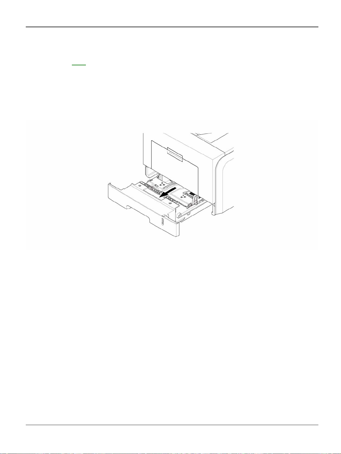
1. Take out the Cassette.
Figure 1
Phaser 3435 5/08 4-3
Page 98
Repairs and Adjustments
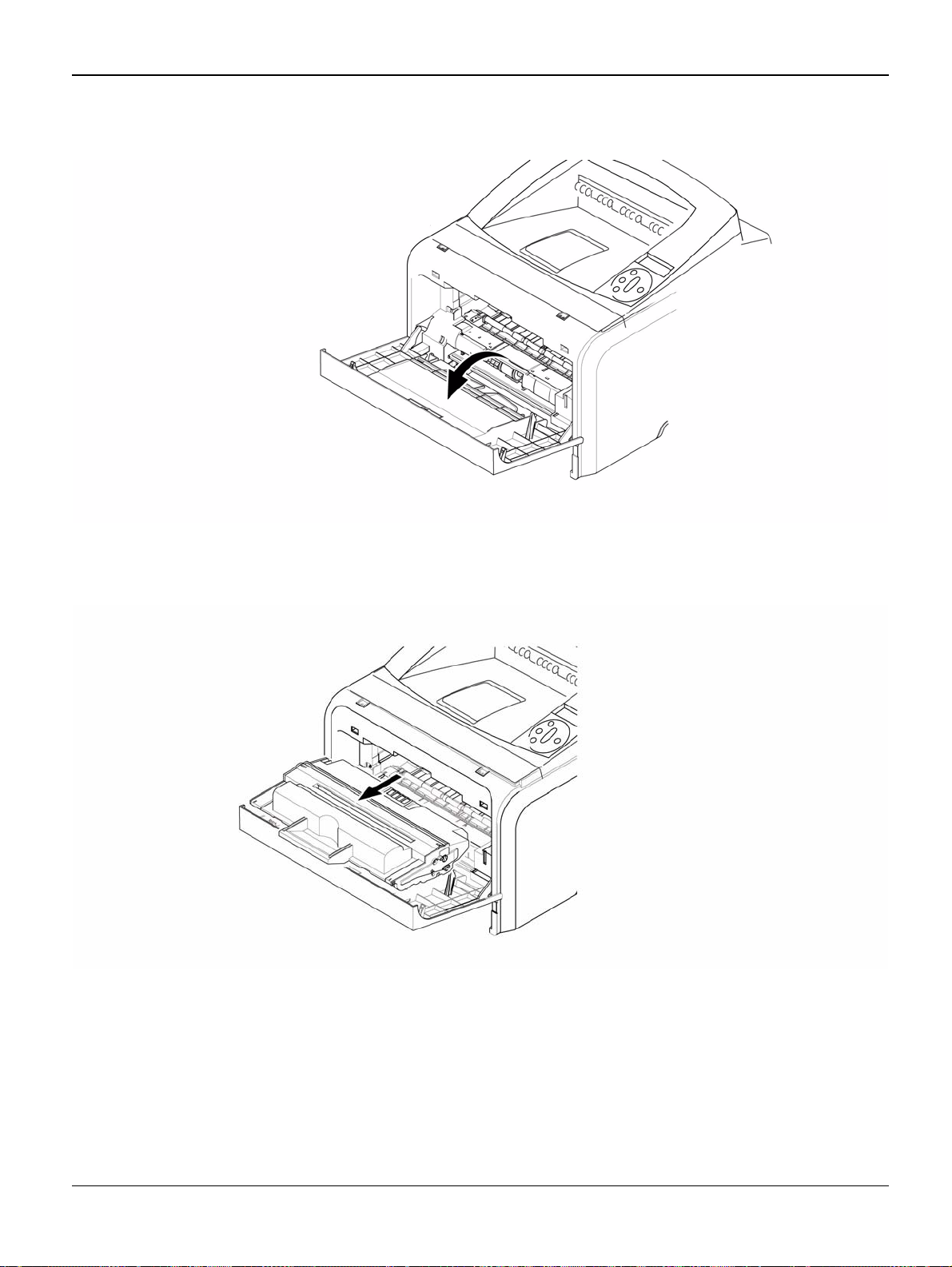
2. Open the Cover.
3. If necessary, remove the print cartridge.
Figure 2
Figure 3
4-4 5/08 Phaser 3435
Page 99
Repairs and Adjustments
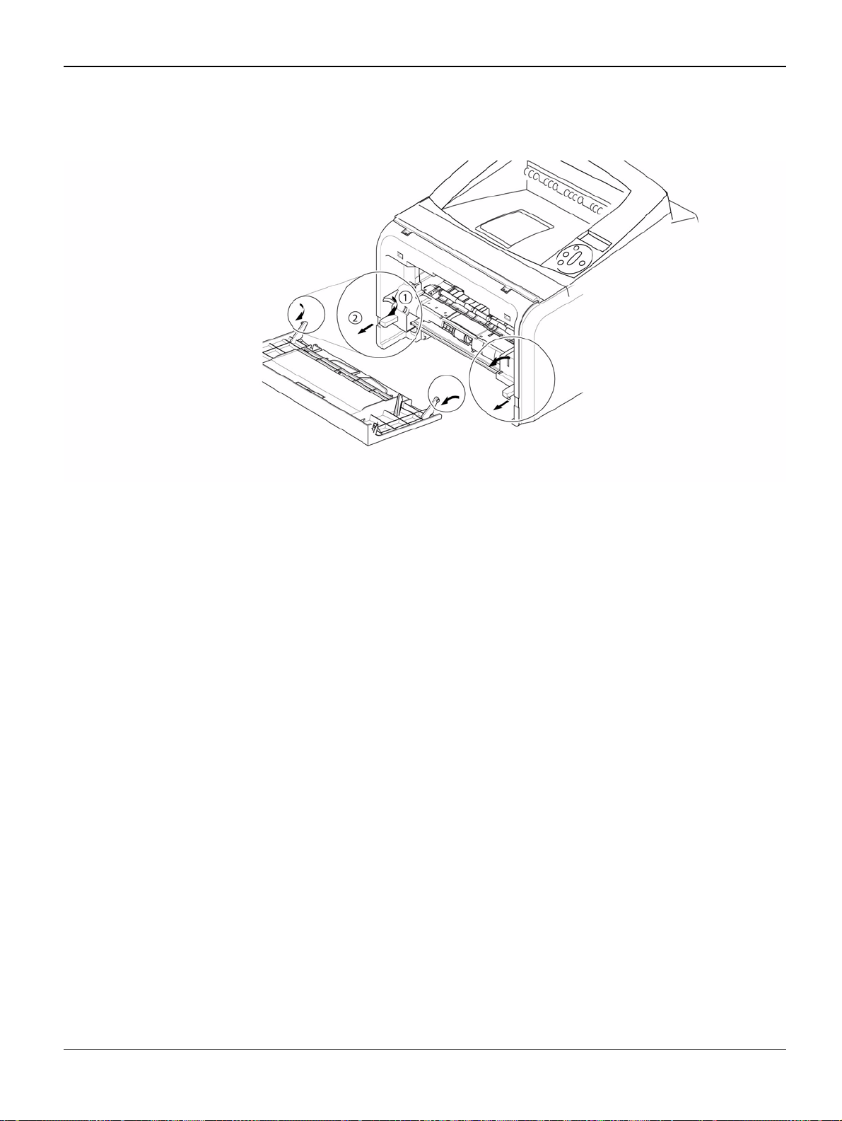
4. To remove the Front Cover, first pull the part below the both side of the Front Cover with a
light pressure to the direction of arrow.
Figure 4
Phaser 3435 5/08 4-5
Page 100

Repairs and Adjustments
REP 2 MP Tray Assembly
Parts List on: PL 3
WARNING
Switch off the electricity to the machine. Disconnect the power cord from the customer supply
while performing tasks that do not need electricity. Electricity can cause death or injury. Moving
parts can cause injury.
1. Open the MP Tray Assembly
MP tray assembly
Figure 1
4-6 5/08 Phaser 3435
 Loading...