

Page 1
Smart choice for power
Fuse Block
Installation Guide
TFB110/TFB110C
TFB200/TFB200C
TFB300/TFB300C
TFB350/TFB350C
TFB400/TFB400C
www.xantrex.com
Page 2

About Xantrex
Trademarks
Notice of Copyright
Disclaimer
Xantrex Technology Inc., is a world-leading supplier of
advanced power electronics and controls with products
from 50 watt mobile units to 1 MW utility-scale systems
for wind, solar, batteries, fuel cells, microturbines, and
backup power applications in both grid-connected and
stand-alone systems. Xantrex products include
inverters, battery chargers, programmable power
supplies, and variable speed drives that convert, supply,
control, clean, and distribute electrical power.
Trace and Xantrex are registered trademarks of Xantrex
International.
Fuse Block Installation Guide ©June 2002 Xantrex
Technology Inc. All rights reserved.
Since the use of this guide and the conditions or
methods of installation, operation, use and
maintenance of the unit are beyond the control of
Xantrex Technology Inc., the company does not assume
responsibility and expressly disclaims liability for loss,
damage, or expense arising out of or any way connected
with such installation, operation, use, or maintenance.
See pages 12 through 18 in this guide for specific
warranty information.
Installation Guide
Date and Revision
Document Number
Contact Information
2
June 2002, Revision A
973-0019-01-02
Web: www.xantrex.com
Phone: 1.888.608.0721
Fax: 360.435.2229
©2002 Xantrex Technology Inc. All Rights Reserved
P/N 973-0019-01-02 Rev A 06/2002
Page 3

Table of Contents
About Xantrex .............................................................................................. 2
Trademarks ....................................................................................................... 2
Notice of Copyright ..........................................................................................2
Disclaimer......................................................................................................... 2
Date and Revision ............................................................................................ 2
Document Number ........................................................................................... 2
Contact Information ........................................................................................ 2
Introduction .................................................................................................5
Tools/Materials Required .................................................................................. 5
Installation .................................................................................................... 6
Mounting.......................................................................................................... 6
Cable Installation into Fuse Block ................................................................... 7
For Fuse Blocks designed for Series-C Battery Cables .................................. 7
For Fuse Blocks designed for Ring-lugged Battery Cables ........................... 8
Wiring TFBs to the Battery, DC Disconnect, and Inverter ................................9
Care and Maintenance ............................................................................... 10
Fuse Replacement ........................................................................................... 10
Replacement Fuses ..................................................................................... 11
Limited Warranty ....................................................................................... 12
What does this warranty cover and how long does it last? .........................12
What will Xantrex do? ................................................................................... 12
How do you get service? ................................................................................ 13
What does this warranty not cover? ............................................................. 14
DISCLAIMER ....................................................................................................15
Product....................................................................................................... 15
Exclusions ................................................................................................... 16
Information ................................................................................................ 16
WARNING: LIMITATIONS ON USE ................................................................ 17
Return Material Authorization Policy ...........................................................17
Shipping Instructions ................................................................................. 18
If you are returning a product from outside of the USA or Canada..... 18
If you are returning a product to a Xantrex Authorized Service Center
(ASC) ................................................................................................... 18
Service Information.................................................................................... 19
©2002 Xantrex Technology Inc. All Rights Reserved
P/N 973-0019-01-02 Rev A 06/2002
3
Page 4

List of Figures
Figure 1 Fuse Block for Type-C Battery Cables (TFBxxxC)............................... 5
Figure 1a Fuse Block for Ring-lugged Battery Cables(TFBxxx) ........................ 5
Figure 2 Fuse Block Dimensional Drawing .................................................... 6
Figure 3 Installation for Type-C Battery Cables............................................. 7
Figure 4 Installation for Ring-lugged Battery Cables ................................... 8
Figure 5 Wiring TFB’s to the Battery, DC Disconnect, and Inverter .............. 9
Figure 6 Remove the Two Nuts and Washers and Replace Fuse .................. 10
List of Tables
Table 1 Bolt and Nut Sizes ........................................................................... 6
Table 2 Replacement Fuses and Cable Sizes .............................................. 11
Installation Guide
4
©2002 Xantrex Technology Inc. All Rights Reserved
P/N 973-0019-01-02 Rev A 06/2002
Page 5
Introduction
NOTE: These fuse
blocks meet the
National
Electrical Code
requirements for
overcurrent
protection.
Xantrex offers
the DC175 and
DC250 in an
enclosure for
applications
requiring NEC
compliance for
both overcurrent
protection and a
DC disconnect.
Tools/Materials Required
The Trace™ brand fuse block (TFB) protects the power
system’s DC wiring should an overcurrent condition
occur. The fuse block is placed between the battery’s
ungrounded conductor (usually the positive cable) and
the DC input terminal of the inverter.
The TFBs include a fast acting, current limiting class-T
fuse providing extremely fast protection when a short
circuit occurs. When the fuse is properly matched to the
system current, its time delay allows the inverter to
surge to full power without blowing the fuse. A plastic
cover prevents accidental short circuits to the fuse
terminals. Fuse sizes include 110, 200, 300, 350 and
400 amps.
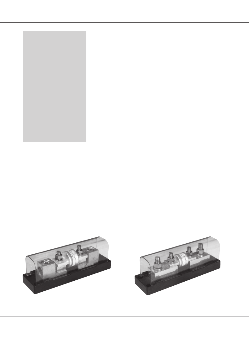
There are two types of fuse blocks available. The
TFBxxxC fuse block has “set” screw lugs for cables with
no terminal connector’s on the ends (hereto referred to
as C-type battery cables). The TFBxxx fuse block has
stainless steel bolt connections for cables with ring
terminals (hereto referred to as ring-lugged battery
cables). Both fuse blocks include a black polycarbonate,
fiberglass reinforced base and a clear polycarbonate
snap-on cover.
• 4 screws (type depending on mounting material)
• 5/16 inch allen wrench (for C-type fuse blocks only)
• 9/16 inch socket for 3/8" hex nuts
• 1/2 inch socket for 5/16" hex nuts
• assorted screwdrivers
• knife
Figure 1
Fuse Block for C-type
Battery Cables (TFBxxxC)
©2002 Xantrex Technology Inc. All Rights Reserved
P/N 973-0019-01-02 Rev A 06/2002
Figure 1a
Fuse Block for Ring-lugged
Battery Cables (TFBxxx)
5
Page 6
Installation
Mounting
NOTE: It is not
recommended to
locate the fuse
block inside the
enclosure with
the batteries
where explosive
gases may exist.
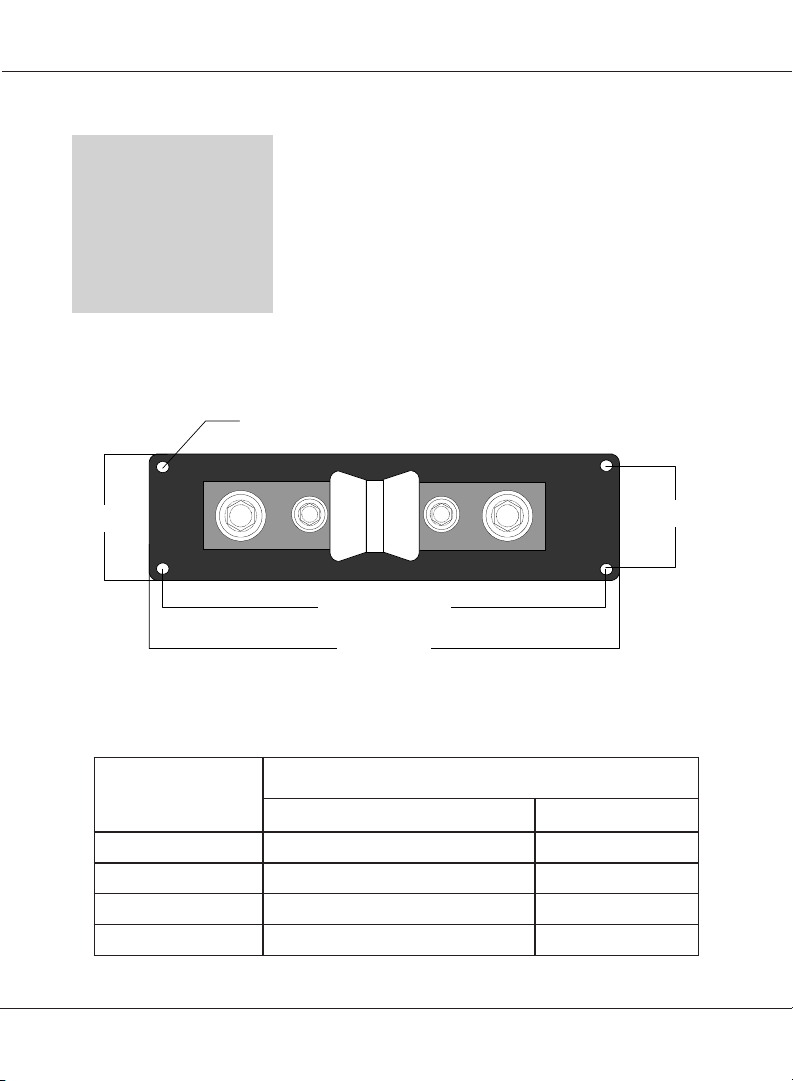
2.00"
(50.6 cm)
Locate the fuse block within 18 inches (45 cm) of the
battery. It should be placed in a location where it is
easily accessible should the fuse need replacing.
1. Squeeze the clear plastic protective cover and
remove it from the fuse block base.
2. Use the fuse block base as a template for location of
the four mounting holes. The fuse block should be
mounted to a secure surface. Allow at least 6 inches
(15 cm) from the fuse contacts to allow for removal
without shorting to a grounded object.
3. Use appropriate hardware (not supplied) to mount
the fuse block.
X4 holes for #10 screws
A
6.250" (158.75 cm)
7.0" (177.8 cm)
BB
A
Installation Guide
Figure 2
Fuse Block Dimensional Drawing
(Not to scale)
1.32"
(33.53 cm)
epyTkcolBesuF
eziSguL/tloB
)tun/tlob(xxxBFT
)wercstes(CxxxBFT
002,011BFTtunxehhtiwtlob81-8/3tunxehhtiwtlob01-61/5
004,053,003BFTtunxehhtiwtlob81-8/3tunxehhtiwtlob81-8/3
C002,C011BFTselbactuc0/2-4#rofsgul0/2#tunxehhtiwtlob01-61/5
C004,C053,C003BFTselbactucMCM052-4#rofsgulMCM052tunxehhtiwtlob81-8/3
AB
Table 1
Bolt and Nut Sizes
6
©2002 Xantrex Technology Inc. All Rights Reserved
P/N 973-0019-01-02 Rev A 06/2002
Page 7

Installation (continued)
Cable Installation into Fuse Block
For Fuse Blocks designed for C-Type Battery Cables (TFBxxxC)
1. Strip back 1 inch (2.5 cm) of the insulation on the
battery cable.
2. Insert the cable into the terminal block (ensure all
conductor strands are in the block)
See Figure 3.
3. Tighten the hex screws to 10-15 ft/lbs.
4. Repeat Steps 2 and 3 for the connection to the other
end of the fuse block.
Stripped
back 1 inch
Installation for C-Type Battery Cables
©2002 Xantrex Technology Inc. All Rights Reserved
P/N 973-0019-01-02 Rev A 06/2002
Figure 3
7
Page 8

Installation (continued)
Cable Installation into Fuse Block (continued)
For Fuse Blocks designed for Ring-lugged Battery Cables (TFBxxx)
NOTE: Do not place
anything
between the
ring-lug on the
battery cable
and the terminal
surface.
A. If necessary, install the ring-lugs (not supplied) onto
the battery cables. Ensure the terminal connector’s
have a 3/8" diameter opening for placement over the
stud connector on the fuse block.
1. Remove the 3/8" hex nut and split washers from the
fuse block.
2. Place the cable ring lugs over the 3/8-18 bolt on the
fuse block assembly and reinstall the split washer
and hex nut.
See Figure 4.
3. Tighten the hex nuts to 10-15 ft/lbs.
4. Repeat Steps 2, 3, and 4 for connection to the other
end of the fuse block.
Ring-lug on
Battery Cables
8
hex nut
Terminal surface
3/8-18
bolt
split-
washers
split-
washers
3/8-18
bolt
Installation Guide
Terminal surface
Figure 4
Installation for Ring-lugged Battery Cables
©2002 Xantrex Technology Inc. All Rights Reserved
hex nut
Ring-lug on
Battery Cables
P/N 973-0019-01-02 Rev A 06/2002
Page 9

Installation (continued)
Wiring TFBs to the Battery, DC Disconnect, and Inverter
300 AMP
FUSE CLASS T
TFB FUSE BLOCK FOR
C-TYPE
BATTERY CABLES
300 AMP
FUSE CLASS T
+
BATTERY
+
BATTERY
-
*DC
DISCONNECT
-
INVERTER
*DC DISCONNECT MAY NOT
BE REQUIRED IN ALL
APPLICATIONS
INVERTER
TFB FUSE BLOCK
FOR RING-LUGGED
BATTERY CABLES
Wiring TFBs to the Battery, DC Disconnect, and Inverter
©2002 Xantrex Technology Inc. All Rights Reserved
P/N 973-0019-01-02 Rev A 06/2002
*DC
DISCONNECT
Figure 5
*DC DISCONNECT MA Y NOT
BE REQUIRED IN ALL
APPLICATIONS
9
Page 10

Care and Maintenance
Fuse Replacement
WARNING:
BEFORE
REPLACING
THE FUSE,
DISCONNECT ALL
POWER SOURCES
AND TURN OFF
ALL LOADS.
NOTE: If the system
also contains a
DC disconnect,
switch it to OFF
before replacing
the fuse.
NOTE: Fuses are NOT
covered under the
limited warranty.
split-washer
Before replacing the fuse, determine and correct the
cause of the overcurrent condition.
1. Use a hex socket and remove the two nuts (and split
washers) securing the fuse. Note the hardware
installed and the order of how it is stacked. This is
important to prevent excess heat which can cause
the fuse to open again.
2. Remove the open fuse and replace it with a known
good one.
3. Reinstall the hardware as it was originally stacked on
the fuse.
4. Tighten the hex nuts securing the fuse to
10-15 ft/lbs.
5. Double-check the battery cable connections and
verify all connections are properly tightened .
hex nut
bolt
fuse
300 AMP
FUSE CLASS T
hex nut
split-washer
bolt
Installation Guide
10
hex nut
split-washer
bolt
fuse
300 AMP
FUSE CLASS T
hex nut
split-washer
bolt
Figure 6
Remove the Two Nuts and Washers and Replace Fuse
©2002 Xantrex Technology Inc. All Rights Reserved
P/N 973-0019-01-02 Rev A 06/2002
Page 11

Care and Maintenance (continued)
Replacement Fuses
WARNING:
REPLACE FUSE
WITH ONLY THE
SAME TYPE
(CLASS T) AND
RATING
(AMPERAGE/
VOLTAGE).
NOTE: The temperature
rating of the
cable sizes
specified in
Table 2 are 75 °C
in free-air based
on an ambient air
temperature of
30 °C (86 °F).
Replacement fuses are available from Xantrex
Technology Inc. These fuses fit either the TFBxxx or
TFBxxxC models (of the same rating only).
See Table 2 for part numbers for replacement fuses.
#BFTegarepmA
C011FBT/011BFTspma011011FTmm2.12/GWA4#
C002FBT/002BFTspma002002FTmm4.76/GWA0/2#
C003FBT/003BFTspma003003FTmm701/GWA0/4#
C053FBT/053BFTspma053053FTmm701/GWA0/4#
C004FBT/004BFTspma004004FTmm701/GWA0/4#
Replacement Fuses and Cable Sizes
©2002 Xantrex Technology Inc. All Rights Reserved
P/N 973-0019-01-02 Rev A 06/2002
Table 2
tnemecalpeR
esuF
eziSelbaC
2
2
2
2
2
11
Page 12

Limited Warranty
What does this warranty cover and how long does it last?
NOTE: Fuses are NOT
covered under the
limited warranty.
What will Xantrex do?
This Limited Warranty is provided by Xantrex
Technology, Inc. (“Xantrex”) and covers defects in
workmanship and materials in your Fuse Block. This
warranty lasts for a Warranty Period of two years from
the date of purchase at point of sale to you, the original
end user customer.
Xantrex will, at its option, repair or replace the defective
product free of charge, provided that you notify Xantrex
of the product defect within the Warranty Period, and
provided that Xantrex through inspection establishes
the existence of such a defect and that it is covered by
this Limited Warranty.
Xantrex will, at its option, use new and/or reconditioned
parts in performing warranty repair and building
replacement products. Xantrex reserves the right to use
parts or products of original or improved design in the
repair or replacement. If Xantrex repairs or replaces a
product, its warranty continues for the remaining
portion of the original Warranty Period or 90 days from
the date of the return shipment to the customer,
whichever is greater. All replaced products and all parts
removed from repaired products become the property
of Xantrex.
Xantrex covers both parts and labor necessary to repair
the product, and return shipment to the customer via a
Xantrex-selected non-expedited surface freight within
the contiguous United States and Canada. Alaska and
Hawaii are excluded. Contact Xantrex Customer Service
for details on freight policy for return shipments outside
of the contiguous United States and Canada.
Installation Guide
12
©2002 Xantrex Technology Inc. All Rights Reserved
P/N 973-0019-01-02 Rev A 06/2002
Page 13

Limited Warranty (continued)
How do you get service?
If your product requires troubleshooting or warranty
service, contact your merchant. If you are unable to
contact your merchant, or the merchant is unable to
provide service, contact Xantrex directly at:
Phone: 360.435.8826
Fax: 360.474.0616
Email: Tracewarranty@xantrex.com
Direct returns may be performed according to the
Xantrex Return Material Authorization Policy described
in your product manual. For some products, Xantrex
maintains a network of regional Authorized Service
Centers. Call Xantrex or check our website to see if your
product can be repaired at one of these facilities.
In any warranty claim, dated proof of purchase must
accompany the product and the product must not have
been disassembled or modified without prior written
authorization by Xantrex.
Proof of purchase may be in any one of the following
forms:
• the dated purchase receipt from the original purchase
of the product at point of sale to the end user, or
• the dated dealer invoice or purchase receipt showing
• the dated invoice or purchase receipt showing the
©2002 Xantrex Technology Inc. All Rights Reserved
P/N 973-0019-01-02 Rev A 06/2002
original equipment manufacturer (OEM) status, or
product exchanged under warranty.
13
Page 14

Limited Warranty (continued)
What does this warranty not cover?
NOTE: Fuses are NOT
covered under the
limited warranty.
This Limited Warranty does not cover normal wear and
tear of the product or costs related to the removal,
installation, or troubleshooting of the customer’s
electrical systems. This warranty does not apply to and
Xantrex will not be responsible for any defect in or
damage to:
a) the product if it has been misused, neglected,
improperly installed, physically damaged or altered,
either internally or externally, or damaged from
improper use or use in an unsuitable environment;
b) the product if it has been subjected to fire, water,
generalized corrosion, biological infestations, or
input voltage that creates operating conditions
beyond the maximum or minimum limits listed in
the Xantrex product specifications including high
input voltage from generators and lightning strikes;
c) the product if repairs have been done to it other than
by Xantrex or its authorized service centers
(hereafter “ASCs”);
d) the product if it is used as a component part of a
product expressly warranted by another
manufacturer;
e) the product if its original identification (trademark,
serial number) markings have been defaced,
altered, or removed.
Installation Guide
14
©2002 Xantrex Technology Inc. All Rights Reserved
P/N 973-0019-01-02 Rev A 06/2002
Page 15

Limited Warranty (continued)
DISCLAIMER
Product
THIS LIMITED WARRANTY IS THE SOLE AND
EXCLUSIVE WARRANTY PROVIDED BY XANTREX IN
CONNECTION WITH YOUR XANTREX PRODUCT AND
IS, WHERE PERMITTED BY LAW, IN LIEU OF ALL OTHER
WARRANTIES, CONDITIONS, GUARANTEES,
REPRESENTATIONS, OBLIGATIONS AND LIABILITIES,
EXPRESS OR IMPLIED, STATUTORY OR OTHERWISE IN
CONNECTION WITH THE PRODUCT, HOWEVER
ARISING (WHETHER BY CONTRACT, TORT,
NEGLIGENCE, PRINCIPLES OF MANUFACTURER’S
LIABILITY, OPERATION OF LAW, CONDUCT,
STATEMENT OR OTHERWISE), INCLUDING WITHOUT
RESTRICTION ANY IMPLIED WARRANTY OR
CONDITION OF QUALITY, MERCHANTABILITY OR
FITNESS FOR A PARTICULAR PURPOSE. ANY IMPLIED
WARRANTY OF MERCHANTABILITY OR FITNESS FOR A
PARTICULAR PURPOSE TO THE EXTENT REQUIRED
UNDER APPLICABLE LAW TO APPLY TO THE
PRODUCT SHALL BE LIMITED IN DURATION TO THE
PERIOD STIPULATED UNDER THIS LIMITED
WARRANTY.
IN NO EVENT WILL XANTREX BE LIABLE FOR ANY
SPECIAL, DIRECT, INDIRECT, INCIDENTAL OR
CONSEQUENTIAL DAMAGES, LOSSES, COSTS OR
EXPENSES HOWEVER ARISING WHETHER IN
CONTRACT OR TORT INCLUDING WITHOUT
RESTRICTION ANY ECONOMIC LOSSES OF ANY KIND,
ANY LOSS OR DAMAGE TO PROPERTY, ANY PERSONAL
INJURY, ANY DAMAGE OR INJURY ARISING FROM OR
AS A RESULT OF MISUSE OR ABUSE, OR THE
INCORRECT INSTALLATION, INTEGRATION OR
OPERATION OF THE PRODUCT.
©2002 Xantrex Technology Inc. All Rights Reserved
P/N 973-0019-01-02 Rev A 06/2002
15
Page 16

Limited Warranty (continued)
Exclusions
If this product is a consumer product, federal law does
not allow an exclusion of implied warranties. To the
extent you are entitled to implied warranties under
federal law, to the extent permitted by applicable law
they are limited to the duration of this Limited Warranty.
Some states and provinces do not allow limitations or
exclusions on implied warranties or on the duration of an
implied warranty or on the limitation or exclusion of
incidental or consequential damages, so the above
limitation(s) or exclusion(s) may not apply to you. This
Limited Warranty gives you specific legal rights. You may
have other rights which may vary from state to state or
province to province.
Information
WITHOUT LIMITING THE GENERALITY OF THE
FOREGOING, UNLESS SPECIFICALLY AGREED TO BY IT
IN WRITING, XANTREX
(a) MAKES NO WARRANTY AS TO THE ACCURACY,
SUFFICIENCY OR SUITABILITY OF ANY TECHNICAL OR
OTHER INFORMATION PROVIDED IN MANUALS OR
OTHER DOCUMENTATION PROVIDED BY IT IN
CONNECTION WITH THE PRODUCT; AND
16
(b) ASSUMES NO RESPONSIBILITY OR LIABILITY FOR
LOSSES, DAMAGES, COSTS OR EXPENSES, WHETHER
SPECIAL, DIRECT, INDIRECT, CONSEQUENTIAL OR
INCIDENTAL, WHICH MIGHT ARISE OUT OF THE USE
OF SUCH INFORMATION.
THE USE OF ANY SUCH INFORMATION WILL BE
ENTIRELY AT THE USER’S RISK.
Installation Guide
©2002 Xantrex Technology Inc. All Rights Reserved
P/N 973-0019-01-02 Rev A 06/2002
Page 17

Limited Warranty (continued)
WARNING: LIMITATIONS ON USE
NOTE: DO NOT RETURN
PRODUCTS TO
THIS ADDRESS.
Please call your
Xantrex Customer
Service Representative for
return mailing
instructions.
The Fuse Block is not intended for use in connection
with life support systems and Xantrex makes no
warranty or representation in connection with any use of
the product for such purposes.
Xantrex Technology, Inc.
8999 Nelson Way
Burnaby, British Columbia
Canada
V5A 4B5
Return Material Authorization Policy
Before returning a product directly to Xantrex you must
obtain a Return Material Authorization (RMA) number
and the correct factory “Ship To” address. Products
must also be shipped prepaid. Product shipments will
be refused and returned at your expense if they are
unauthorized, returned without an RMA number clearly
marked on the outside of the shipping box, if they are
shipped collect, or if they are shipped to the wrong
location.
When you contact Xantrex to obtain service, please have
your instruction manual ready for reference and be
prepared to supply:
• The part number of your product
• Information about the installation and use of the unit
• Information about the failure and/or reason for the
• A copy of your dated proof of purchase
©2002 Xantrex Technology Inc. All Rights Reserved
P/N 973-0019-01-02 Rev A 06/2002
return
17
Page 18

Limited Warranty (continued)
Shipping Instructions
1. Package the unit safely, preferably using the original
2. Include the following:
3. Ship the unit prepaid to the address provided by
box and packing materials. Please ensure that your
product is shipped fully insured in the original
packaging or equivalent. This warranty will not apply
where the product is damaged due to improper
packaging.
• the RMA number supplied by Xantrex
Technology Inc clearly marked on the outside
of the box,
• a return address where the unit can be shipped
(post office boxes are not acceptable),
• a contact telephone number where you can be
reached during work hours, and
• a brief description of the problem.
your Xantrex customer service representative.
If you are returning a product from outside of the USA or Canada
In addition to the above, you MUST include return
freight funds and are fully responsible for all
documents, duties, tariffs, and deposits.
Installation Guide
If you are returning a product to a Xantrex Authorized Service Center (ASC)
A Xantrex return material authorization (RMA) number
is not required. However, you must contact the ASC prior
to returning the product or presenting the unit to verify
any return procedures that may apply to that particular
facility.
18
©2002 Xantrex Technology Inc. All Rights Reserved
P/N 973-0019-01-02 Rev A 06/2002
Page 19

Service Information
Part Number:
Purchase Date:
Problem:
Include a telephone number where you can be reached
during business hours and a complete return shipping
address (P.O. Box numbers are not acceptable).
Name:
Address:
City:
State / Province:
Zip / Postal Code:
Country:
Phone:
FAX :
Email Address:
©2002 Xantrex Technology Inc. All Rights Reserved
P/N 973-0019-01-02 Rev A 06/2002
19
Page 20

Xantrex Technology Inc.
1 888 608 0721 Phone
1 360 435 2229 Fax
www.xantrex.com
Installation Guide
973-0019-01-02 Rev A 06/2002
Printed in the USA
 Loading...