

Page 1
Sine Wave Plus AC Conduit Box (ACCB) Owner’s Guide
ACCB
Owner’s Guide
Page 2

Page 3

Sine Wave Plus AC Conduit Box
(ACCB)
Installation Guide
Page 4

About Xantrex
Xantrex Technology Inc. is a world-leading supplier of advanced power electronics and controls with products from
50 watt mobile units to one MW utility-scale systems for wind, solar, batteries, fuel cells, microturbines, and backup
power applications in both grid-connected and stand-alone systems. Xantrex products include inverters, battery
chargers, programmable power supplies, and variable speed drives that convert, supply, control, clean, and distribute
electrical power.
Trademarks
Sine Wave Plus AC Conduit Box is a trademark of Xantrex International. Xantrex is a registered trademark of
Xantrex International.
Other trademarks, registered trademarks, and product names are the property of their respective owners and are used
herein for identification purposes only.
Notice of Copyright
Sine Wave Plus AC Conduit Box (ACCB) Installation Guide © August 2003 Xantrex International. All rights
reserved.
Disclaimer
UNLESS SPECIFICALLY AGREED TO IN WRITING, XANTREX TECHNOLOGY INC. (“XANTREX”)
(a) MAKES NO WARRANTY AS TO THE ACCURACY, SUFFICIENCY OR SUITABILITY OF ANY
TECHNICAL OR OTHER INFORMATION PROVIDED IN ITS MANUALS OR OTHER DOCUMENTATION.
(b) ASSUMES NO RESPONSIBILITY OR LIABILITY FOR LOSS OR DAMAGE, WHETHER DIRECT,
INDIRECT, CONSEQUENTIAL OR INCIDENTAL, WHICH MIGHT ARISE OUT OF THE USE OF SUCH
INFORMATION. THE USE OF ANY SUCH INFORMATION WILL BE ENTIRELY AT THE USER’S RISK.
Date and Revision
August 2003 Revision A
Part Number
975-0046-01-01
Contact Information
Telephone: 1-800-670-0707 (toll free in North America)
1-360-435-8826 (direct)
Fax: 1-360-435-3547
Email: CustomerService@xantrex.com
Web: www.xantrex.com
Page 5

About This Guide
Purpose
The purpose of this Installation Guide is to provide explanations and
procedures for installing and operating the Sine Wave Plus AC Conduit
Box (ACCB).
Scope
The Sine Wave Plus AC Conduit Box (ACCB) Installation Guide
provides safety guidelines and procedures for installing and operating the
ACCB.
Audience
This Guide is intended for those who need to install and operate the Sine
Wave Plus AC Conduit Box. Only skilled personnel, such as certified
electricians and solar technicians should attempt installation of this
equipment. Skills required include the ability to read and understand how
to follow single line wiring diagrams.
Organization
This Guide is organized into two chapters.
Chapter 1, “Installation” provides installation and wiring instructions for
the Sine Wave Plus AC Conduit Box (ACCB).
Chapter 2, “Operating the ACCB” describes the different modes and
operation of the Bypass Switch on the ACCB.
Warranty and product information is provided at the end of the guide.
975-0046-01-01 iii
Page 6
About This Guide
Conventions Used
The following conventions are used in this guide.
WARNING
Warnings identify conditions that could result in personal injury or loss of life.
CAUTION
Cautions identify conditions or practices that could result in damage to
the unit or other equipment.
Important:
to know, but not as serious as a caution or warning.
These notes describe things which are important for you
Abbreviations and Acronyms
AC Alternating Current
ACCB AC Conduit Box
ALM Auxiliary Load Module
ASC Authorized Service Center
AWG American Wire Gauge
DC Direct Current
EPO Emergency Power Off
GSM Generator Start Module
ICA Inverter Communications Adapter
ICM Inverter Control Module
ISC-S Inverter Stacking Control – Series
RMA Return Material Authorization
SP-1 Safety Plate
SEMS Screw Screw with a captive lockwasher
Related Information
You can find more information about Xantrex Technology Inc. as well as
its products and services at www.xantrex.com
iv 975-0046-01-01
Page 7

Important Safety Instructions
WARNING
This chapter contains important safety and operating instructions for Sine Wave
Plus AC Conduit Boxes (ACCB). Read and keep this Sine Wave Plus AC
Conduit Box (ACCB) Installation Guide for future reference.
1. Before installing the ACCB, read all instructions and cautionary
markings on the ACCB and all appropriate sections of this guide.
2. Do not expose the ACCB to rain, snow, or spray. To reduce risk of
fire hazard, do not cover or obstruct the ventilation openings. Do not
install the ACCB in a zero-clearance compartment. Overheating may
result. Minimum clearance for ventilation around the unit must be six
inches at the end and three inches top and bottom.
3. Use only attachments recommended or sold by the manufacturer.
Doing otherwise may result in a risk of fire, electric shock, or injury
to persons.
4. The ACCB is designed to be permanently connected to your inverter.
It can be mounted on a vertical surface (or wall) or on a shelf. Xantrex
recommends that all wiring be done by a certified technician or
electrician to ensure adherence to the local and national electrical
codes applicable in your application.
5. To avoid a risk of fire and electric shock, make sure that existing
wiring is in good condition and that wire is not undersized. Do not
operate the ACCB, or inverter, with damaged or substandard wiring.
6. Do not install the ACCB if it has received a sharp blow, been
dropped, or otherwise damaged in any way. If the unit is damaged,
see the Warranty section at the end of this guide.
7. To reduce the risk of electrical shock, disconnect all power to the
ACCB and the Sine Wave Plus Inverter/Charger before attempting
any maintenance or cleaning or working on the ACCB.
8. The ACCB is provided with an equipment-grounding conductor
which must be connected to the inverter/system equipment ground.
975-0046-01-01 v
Page 8

Important Safety Instructions
Explosive gas precautions
1. Working in the vicinity of lead-acid batteries is dangerous. Batteries
generate explosive gases during normal operation. Therefore, you
must read this guide and follow the instructions exactly before
installing the ACCB.
2. To reduce the risk of battery explosion, follow these instructions and
those published by the battery manufacturer and the manufacturer of
the equipment in which the battery is installed.
vi 975-0046-01-01
Page 9

Contents
Important Safety Instructions
1
Installation
Introduction - - - - - - - - - - - - - - - - - - - - - - - - - - - - - - - - - - - - - - - - - - - - - - - - - - - - -1–2
Specifications- - - - - - - - - - - - - - - - - - - - - - - - - - - - - - - - - - - - - - - - - - - - - - - - - - - -1–3
Bypass Switch Assembly - - - - - - - - - - - - - - - - - - - - - - - - - - - - - - - - - - - - - - - - - - - -1–4
Safety Plate (SP-1) - - - - - - - - - - - - - - - - - - - - - - - - - - - - - - - - - - - - - - - - - - - - - - - -1–4
Code Compliance - - - - - - - - - - - - - - - - - - - - - - - - - - - - - - - - - - - - - - - - - - - - - - - - -1–5
Installation Tools and Materials- - - - - - - - - - - - - - - - - - - - - - - - - - - - - - - - - - - - - - - -1–5
Wiring Scenarios - - - - - - - - - - - - - - - - - - - - - - - - - - - - - - - - - - - - - - - - - - - - - - - - -1–6
Off-Grid Applications - - - - - - - - - - - - - - - - - - - - - - - - - - - - - - - - - - - - - - - - - - -1–6
On-Grid Applications - - - - - - - - - - - - - - - - - - - - - - - - - - - - - - - - - - - - - - - - - - - -1–6
Pre-installation - - - - - - - - - - - - - - - - - - - - - - - - - - - - - - - - - - - - - - - - - - - - - - - - - - -1–7
Location - - - - - - - - - - - - - - - - - - - - - - - - - - - - - - - - - - - - - - - - - - - - - - - - - - - - -1–7
Ventilation Requirements - - - - - - - - - - - - - - - - - - - - - - - - - - - - - - - - - - - - - - - - -1–7
Knockout Preparation - - - - - - - - - - - - - - - - - - - - - - - - - - - - - - - - - - - - - - - - - - - -1–8
Accessory Cable Slots - - - - - - - - - - - - - - - - - - - - - - - - - - - - - - - - - - - - - - - - - - -1–9
Removing and Replacing the ACCB Cover - - - - - - - - - - - - - - - - - - - - - - - - - - - -1–11
Installing Additional Breakers - - - - - - - - - - - - - - - - - - - - - - - - - - - - - - - - - - - - -1–13
Mounting the ACCB to the Inverter - - - - - - - - - - - - - - - - - - - - - - - - - - - - - - - - - - - -1–14
Pre-Wiring Preparation - - - - - - - - - - - - - - - - - - - - - - - - - - - - - - - - - - - - - - - - - - - - 1–15
Accessing the Terminal Blocks - - - - - - - - - - - - - - - - - - - - - - - - - - - - - - - - - - - -1–15
Wire Sizes and Disconnect Requirements - - - - - - - - - - - - - - - - - - - - - - - - - -1–15
Wiring for Off-Grid Applications Using an AC Distribution Panel
and an External Generator Disconnect - - - - - - - - - - - - - - - - - - - - - - - - - - - - - - - - - -1–18
Wiring for Off-Grid Applications using an AC Distribution Panel
and an Internal Generator Disconnect- - - - - - - - - - - - - - - - - - - - - - - - - - - - - - - - - - -1–22
Wiring for Off-Grid Applications Using Additional Circuit Breakers in the ACCB Only 1–26
Wiring for On-Grid Applications Using an AC Distribution Panel
and an Internal Generator Disconnect Breaker - - - - - - - - - - - - - - - - - - - - - - - - - - - - -1–30
Wiring for On-Grid Applications Using Additional Circuit Breakers in the ACCB Only 1–34
Additional Accessory Wiring - - - - - - - - - - - - - - - - - - - - - - - - - - - - - - - - - - - - - - - - 1–38
Wiring for Dual Inverter Configurations - - - - - - - - - - - - - - - - - - - - - - - - - - - - - - - - -1–39
Installing the ISC-S Cable - - - - - - - - - - - - - - - - - - - - - - - - - - - - - - - - - - - - - - - -1–39
AC Neutral Wiring for Dual Configurations - - - - - - - - - - - - - - - - - - - - - - - - - - - -1–39
Installing the Safety Plate- - - - - - - - - - - - - - - - - - - - - - - - - - - - - - - - - - - - - - - - - - -1–40
975-0046-01-01 vii
Page 10

Contents
2
Operating the ACCB
The Bypass Switch- - - - - - - - - - - - - - - - - - - - - - - - - - - - - - - - - - - - - - - - - - - - - - - - 2–2
Operating the Bypass Switch - - - - - - - - - - - - - - - - - - - - - - - - - - - - - - - - - - - - - - - - - 2–2
Normal Operation - - - - - - - - - - - - - - - - - - - - - - - - - - - - - - - - - - - - - - - - - - - - - - 2–3
Bypass Operation - - - - - - - - - - - - - - - - - - - - - - - - - - - - - - - - - - - - - - - - - - - - - - 2–3
AC Input/Output Off - - - - - - - - - - - - - - - - - - - - - - - - - - - - - - - - - - - - - - - - - - - - 2–4
Dual Inverters: 240 Vac Loads - - - - - - - - - - - - - - - - - - - - - - - - - - - - - - - - - - - - - - - - 2–4
Warranty and Product Information
Warranty - - - - - - - - - - - - - - - - - - - - - - - - - - - - - - - - - - - - - - - - - - - - - - - - - - - - WA–1
Return Material Authorization Policy - - - - - - - - - - - - - - - - - - - - - - - - - - - - - - - - - WA–3
Out of Warranty Service - - - - - - - - - - - - - - - - - - - - - - - - - - - - - - - - - - - - - - - - - - WA–4
Information About Your System- - - - - - - - - - - - - - - - - - - - - - - - - - - - - - - - - - - - - WA–4
Index
- - - - - - - - - - - - - - - - - - - - - - - - - - - - - - - - - - - - - - - - - - - - - - - - - - - - - - - - - - IX–1
- - - - - - - - - - - - - - - - - - - - - - - - - - - - - WA–1
viii 975-0046-01-01
Page 11

Figures
Figure 1-1 AC Conduit Box, Front View - - - - - - - - - - - - - - - - - - - - - - - - - - - - - - - -1–2
Figure 1-2 ACCB Dimensions (not to scale) - - - - - - - - - - - - - - - - - - - - - - - - - - - - - -1–3
Figure 1-3 Safety Plate SP-1 - - - - - - - - - - - - - - - - - - - - - - - - - - - - - - - - - - - - - - - -1–4
Figure 1-4 Clearance Requirements for Ventilation - - - - - - - - - - - - - - - - - - - - - - - - -1–7
Figure 1-5 SW Plus Inverter, AC Side Showing Knockout Location- - - - - - - - - - - - - -1–8
Figure 1-6 Knockouts on ACCB Top Cover for Additional Circuit Breakers - - - - - - - -1–9
Figure 1-7 ACCB Knockout Locations - - - - - - - - - - - - - - - - - - - - - - - - - - - - - - - - 1–10
Figure 1-8 ACCB Cover Removal - - - - - - - - - - - - - - - - - - - - - - - - - - - - - - - - - - -1–12
Figure 1-9 Installing Additional Breakers on the DIN rail - - - - - - - - - - - - - - - - - - - - 1–13
Figure 1-10 Installing the ACCB on the Sine Wave Plus Inverter Charger- - - - - - - - - -1–14
Figure 1-11 ACCB AC Terminal Block Distribution Blocks - - - - - - - - - - - - - - - - - - -1–16
Figure 1-12 ACCB Internal Components and Factory-installed Wiring- - - - - - - - - - - - 1–17
Figure 1-13 ACCB AC Terminal Block For Customer-installed Wiring - - - - - - - - - - -1–17
Figure 1-14 Wiring an Off-Grid Application Using an AC Distribution Panel
and an External Generator Disconnect Switch - - - - - - - - - - - - - - - - - - - - 1–18
Figure 1-15 Ground Connections for an Off-Grid Application with an AC Distribution
Panel and an External Generator Disconnect - - - - - - - - - - - - - - - - - - - - -1–19
Figure 1-16 Neutral Connections for an Off-Grid Application with an AC Distribution
Panel and an External Generator Disconnect - - - - - - - - - - - - - - - - - - - - -1–20
Figure 1-17 Hot Connections for an Off-grid Application with an AC Distribution
Panel and an External Generator Disconnect - - - - - - - - - - - - - - - - - - - - -1–21
Figure 1-18 Wiring an Off-grid Application Using an AC Distribution Panel
and an Internal Generator Disconnect Breaker - - - - - - - - - - - - - - - - - - - -1–22
Figure 1-19 Ground Connections for an Off-Grid Application with an AC Distribution
Panel and an Internal Generator Disconnect Breaker- - - - - - - - - - - - - - - - 1–23
Figure 1-20 Neutral Connections for an Off-Grid Application with an AC Distribution
Panel and an Internal Generator Disconnect - - - - - - - - - - - - - - - - - - - - - 1–24
Figure 1-21 Hot Connections for an Off-Grid Application with an AC Distribution
Panel and an Internal Generator Disconnect - - - - - - - - - - - - - - - - - - - - - 1–25
Figure 1-22 Wiring an Off-Grid Application Using Additional Circuit Breakers
in the ACCB Only- - - - - - - - - - - - - - - - - - - - - - - - - - - - - - - - - - - - - - -1–26
Figure 1-23 Ground Connections for an Off-Grid Application with Additional Circuit
Breakers in the ACCB - - - - - - - - - - - - - - - - - - - - - - - - - - - - - - - - - - - -1–27
Figure 1-24 Neutral Connections for an Off-grid Application with Additional Circuit
Breakers in the ACCB - - - - - - - - - - - - - - - - - - - - - - - - - - - - - - - - - - - - 1–28
Figure 1-25 Hot Connections for an Off-grid Application with Additional Circuit Breakers
in the ACCB1–29
Figure 1-26 Wiring an On-grid Application USING an AC Distribution Panel- - - - - - - 1–30
975-0046-01-01 ix
Page 12

Figures
Figure 1-27 Ground Connections for an On-Grid Application with an AC Distribution
Panel (sub panel) and a Generator Disconnect Breaker in the ACCB - - - - 1–31
Figure 1-28 Neutral Connections for an On-grid Application with an AC Distribution
Panel and internal Generator Disconnect Breaker in the ACCB - - - - - - - - 1–32
Figure 1-29 Hot Connections for an On-Grid Application with an AC Distribution
Panel and an Internal Generator Disconnect - - - - - - - - - - - - - - - - - - - - - 1–33
Figure 1-30 Wiring an On-Grid Application Using Additional Circuit Breakers
in the ACCB Only - - - - - - - - - - - - - - - - - - - - - - - - - - - - - - - - - - - - - - 1–34
Figure 1-31 Ground Connections for an On-grid Application Using Additional Circuit
Breakers in the ACCB Only- - - - - - - - - - - - - - - - - - - - - - - - - - - - - - - - 1–35
Figure 1-32 Neutral Connections for an On-Grid Application Using Additional Circuit
Breakers in the ACCB Only- - - - - - - - - - - - - - - - - - - - - - - - - - - - - - - - 1–36
Figure 1-33 Hot Connections for an On-Grid Application Using Additional Circuit Breakers
in the ACCB Only - - - - - - - - - - - - - - - - - - - - - - - - - - - - - - - - - - - - - - 1–37
Figure 1-34 ISC-S Cable in an ISC-S/ICM Cable Slot of the ACCB - - - - - - - - - - - - - 1–39
Figure 1-35 Removing the Sems Screws From the ACCB Top Cover - - - - - - - - - - - - 1–40
Figure 1-36 Installing the Safety Plate SP-1 on the ACCB- - - - - - - - - - - - - - - - - - - - 1–41
Figure 2-1 Bypass Switch Mode Summary - - - - - - - - - - - - - - - - - - - - - - - - - - - - - - 2–2
Figure 2-2 Normal Operation - - - - - - - - - - - - - - - - - - - - - - - - - - - - - - - - - - - - - - - 2–3
Figure 2-3 Bypass Operation- - - - - - - - - - - - - - - - - - - - - - - - - - - - - - - - - - - - - - - - 2–3
Figure 2-4 AC Output OFF - - - - - - - - - - - - - - - - - - - - - - - - - - - - - - - - - - - - - - - - - 2–4
x 975-0046-01-01
Page 13

1
Installation
Chapter 1, “Installation” provides installation and wiring
instructions for the Sine Wave Plus AC Conduit Box (ACCB).
The following topics are covered in this chapter.
For this topic: See:
“Introduction” page 1–2
“Specifications” page 1–3
“Bypass Switch Assembly” page 1–4
“Code Compliance” page 1–5
“Installation Tools and Materials” page 1–5
“Wiring Scenarios” page 1–6
“Pre-installation” page 1–7
“Mounting the ACCB to the Inverter” page 1–14
“Pre-Wiring Preparation” page 1–15
“Off-Grid Wiring” page 1–18
through
page 1–29
“On-Grid Wiring” page 1–30
through
page 1–37
“Wiring for Dual Inverter Configurations” page 1–39
Page 14
Installation
Introduction
The ACCB connects to the AC side of a Sine Wave Plus inverter and
accepts AC conduit runs. It protects the cable connections to the inverter
and provides an inverter bypass (for a single AC source) and AC
disconnect breakers.
Additional circuit breakers may be added to the ACCB. Use Square D,
Type QOU, DIN rail mounted breakers which can be readily purchased
from most electrical suppliers.
Square D filler plates (QOFP) may be used to refill a knockout panel if
the knockout is no longer used or removed in error.
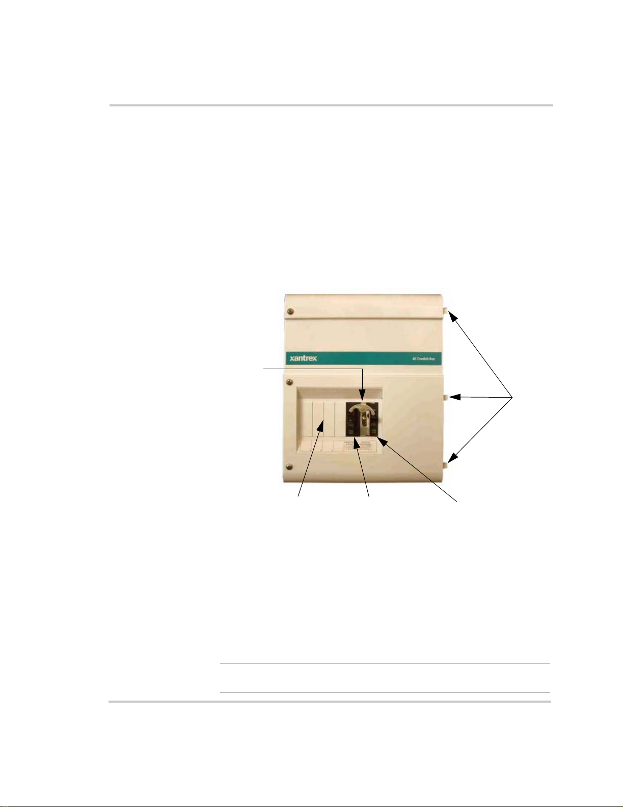
Outer Side
Bypass
Switch
Assembly
Knockout panels for
additional circuit
breakers (x4)
Figure 1-1
AC Conduit Box, Front View
Inverter Bypass
Circuit Breaker
Inverter Side
Cover
tabs
AC Disconnect
Circuit Breaker
The ACCB comes pre-wired for connection to a Sine Wave Plus inverter;
You must provide wires for connection from the AC distribution panel
and from a generator and/or utility to the ACCB. This guide provides
instructions for installing additional circuit breakers into the ACCB and
for connecting the ACCB to the inverter and other system components
(i.e., utility panel, AC distribution panel, grounding, and generator).
Important:
Before installing the ACCB, read all instructions and
cautionary markings located in this guide and in your inverter manual.
1–2 975-0046-01-01
Page 15

Specifications
8 7/8"
(225 mm)
Specifications
Dimensions 15 1/8" (H) x 10 3/4" (W) x 8 7/8" (D)
(384 mm x 273 mm x 225 mm)
Weigh t 12 pounds (5 kg)
Shipping Weight 15 pounds (7 kg)
Operating Voltage 120 Vac
Breakers:
Bypass 60 Amp (SPST)
Inverter Input/Output 60 Amp (DPST)
Operating Temperature -10 to 60 °C (14 to 140 °F)
Storage Temperature -55 to +100 °C (-67 to 212 °F)
Enclosure Indoor rated
Finish Powdercoat
Color White
Regulatory Certified by CSA to UL 1741 and CSA
107.1-01
10 3/4"
(273 mm)
5 3/8"
(137 mm)
15 1/8"
(384 mm)
13 5/8"
(346 mm)
DD
Figure 1-2
3/4"
(20 mm)
1 5/8"
(41 mm)
ACCB Dimensions (not to scale)
7 9/16"
(192 mm)
9 3/16"
(234 mm)
975-0046-01-01 1–3
Page 16

Installation
Bypass Switch Assembly
The bypass switch assembly in the ACCB is designed for 120 Vac
applications and comes with two 60-amp circuit breakers (one SPST and
one DPST). The breaker pair is equipped with a lockout rocker that
allows only one breaker to be ON at any given time.
The bypass switch allows the generator or grid to provide power to the
inverter loads in the event that the inverter is disabled or removed for
service.
For more information see Chapter 2, “Operating the ACCB”, in this
guide.
WARNING: Electrical Hazard
If the inverter is removed from service while the bypass is used, live circuits
inside the ACCB will not be guarded from accidental touch. Be sure to install the
Safety Plate (SP-1) to prevent accidental electrocution if the inverter is removed
from the system.
Safety Plate (SP-1)
A Safety Plate (SP-1) is provided to enclose the ACCB to prevent
accidental contact with any AC power within the ACCB if the inverter is
ever removed from the system configuration. The safety plate is not used
in the initial installation and should be stored in a convenient location.
See page 1–40 for installation instructions for the Safety Plate.
Figure 1-3
Safety Plate SP-1
1–4 975-0046-01-01
Page 17

Code Compliance
Governing installation codes vary depending on the location and type of
installation. Electrical installations must meet local and national wiring
codes. Installations of this equipment should only be performed by skilled
personnel such as qualified electricians and Certified Renewable Energy
(RE) System Installers. For a list of Xantrex Certified RE dealers, please
visit our website at www.XantrexREdealers.com.
Code Compliance
Important:
to starting this installation.
Be sure to obtain the appropriate permits, if necessary, prior
Installation Tools and Materials
Tools Required The following tools may be required for installing this equipment.
❐ Wire strippers
❐ Assorted open-end wrenches or socket wrench and fittings
❐ Torque wrench
❐ Electrical tape
❐ Multi meter (AC/DC volts, frequency)
❐ Assorted Phillips screw drivers
❐ 3/16" Allen/Hex head driver
❐ Slotted screw driver
❐ Level
❐ Pencil
❐ Utility knife
Hardware /
Materials Required
975-0046-01-01 1–5
The following materials may be required for completing this installation.
❐ Conduits, bushings, and appropriate fittings for wire runs
❐ Wire nuts
❐ Electrical wire of appropriate size and length
❐ Breaker Panels
❐ Ground busses, bars, and/or rods
❐ Six #10 wood screws or ¼ inch (6 mm) lag bolts and washers.
Page 18

Installation
Wiring Scenarios
Wiring scenarios will depend upon the configuration of the overall system
(i.e., Off Grid or On Grid). Pre-installation and mounting instructions
apply to all configurations. Follow the instructions from page 1–7 to
page 1–17 for all installations.
After the pre-installation procedures have been completed, select the
wiring scenario that applies to your configuration. Once you have
completed the wiring instructions for your specific application, proceed to
the Operation section.
Off-Grid Applications
The following Off-Grid scenarios are covered in this guide:
• Off-Grid Applications using an AC distribution panel (sub-panel) and
• Off-Grid Applications using an additional circuit breaker in the
• Off-Grid Applications using additional circuit breakers in the ACCB
an external generator disconnect switch.
See page 1–18 for wiring instructions for this application.
ACCB for a generator disconnect.
See page 1–22 for wiring instructions for this application.
for AC loads and a generator disconnect.
See page 1–26 for wiring instructions for this application.
On-Grid Applications
The following On-Grid scenarios are covered in this guide:
• On-Grid Applications with generator backup using an AC
Distribution Panel and an additional circuit breaker in the ACCB for a
generator disconnect.
See page 1–30 for wiring instructions for this application.
• On-Grid Applications using additional circuit breakers in the ACCB
for AC distribution (i.e., no sub panel).
See page 1–34 for wiring instructions for this application.
1–6 975-0046-01-01
Page 19

Pre-installation
WARNING
Ensure that no DC voltage is being supplied to the inverter and that no AC
voltage is present on the AC wiring. Failure to do so could cause serious injury or
death.
Location
Be sure to allow sufficient space for the ACCB to be mounted directly
adjacent to the inverter’s AC side. Also consider the additional weight
and ventilation space requirements of the ACCB.
Ventilation Requirements
Minimum clearance for ventilation around ACCB must be at least
6 inches (152 mm) at the end and at the top. The minimum clearance is
needed to prevent recirculating hot air from the inverter’s exhaust (DC
side) from going back into the inverter’s intake (AC side).
Pre-installation
For maximum ventilation, 12 inches (305 mm) is recommended around
the top.
Please refer to the Sine Wave Plus Inverter/Charger Owner’s Guide for
additional location considerations.
12" (305 mm)
Recommended
6" (152 mm)
Minimum Required
Figure 1-4
6" (152 mm)
Minimum Required
AC Condui t Box
ON
DD
OFFONOFF
Sine W ave Plu s Inve rter / C harger
Clearance Requirements for Ventilation
Set Inverter
OFF SRCH ON CHG
975-0046-01-01 1–7
Page 20
Installation
Knockout Preparation
Knockout preparation should be done before mounting either the inverter
or the ACCB.
1. Remove the appropriate knockouts from the AC side of the inverter,
2. Remove the appropriate knockouts from the ACCB for wire runs
3. If additional circuit breakers are to be added to the ACCB, remove
4. Ensure that there are no metal shavings in the ACCB or inverter
5. Install bushings in knockouts provided to protect the wires from
for cabling from the ACCB terminal block to the inverter terminal
block. See Figure 1-5 for the size and locations of the knockouts on
the Sine Wave Plus Inverter Charger.
from utility and/or inverter panels, a generator, and/or additional
inverters. See Figure 1-7 for the locations of the knockouts on the
ACCB.
one knockout on the top cover for each additional circuit breaker to
be installed. See Figure 1-6 for the locations of the knockouts on the
ACCB top cover.
before proceeding with the rest of the installation.
damage.
Slots for ACCB
Cover Tabs
3/4" and 1"
(19 mm and 25 mm)
Dual Knockouts
Figure 1-5
Important:
may be used for larger size knockout holes if necessary.
1–8 975-0046-01-01
SW Plus Inverter, AC Side Showing Knockout Location
If larger knockouts are required, an electricians knockout punch
Page 21

Knockout Locations
for four additional
circuit breakers
Pre-installation
Figure 1-6
Knockouts on ACCB Top Cover for Additional Circuit
Breakers
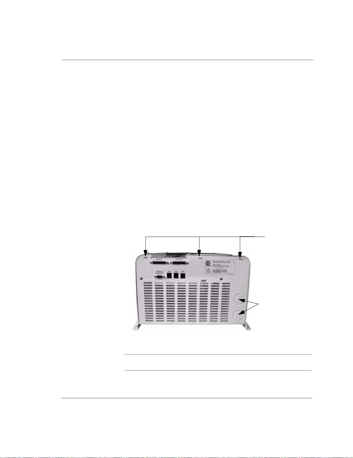
Accessory Cable Slots
Two slots on the top and bottom of the ACCB base are provided to route
the cables for the Inverter Stacking Cable - Series (ISC-S) and the remote
Inverter Control Module (ICM) if used. These slots are covered by small
hole plugs if these accessories are not used.
If your configuration will include the use of the ISC-S or remote ICM
accessories, then determine which slot(s) will be needed and remove the
hole plug(s) for that slot only. Do not remove any hole plugs from slots
that will not be used.
975-0046-01-01 1–9
Page 22

Installation
1/2" and 3/4"
(13 mm and 19 mm)
Dual Knockout
See below for location of
knockouts on vented end.
1/2" and 3/4"
(13mm and 19 mm)
Dual Knockout
3/4" and 1"
(19 mm and 25 mm)
Dual Knockouts (x2)
3/4" and 1"
(19 mm and 25 mm)
Dual Knockouts (x2)
1/2" and 3/4"
(13 mm and 19 mm)
Dual Knockout
3/4" and 1"
(19 mm and 25 mm)
Dual Knockout
Figure 1-7
ACCB Knockout Locations
Slots for optional ISC-S
and ICM cables
Slots for optional
ISC-S and ICM cables
Vented End Knockouts
1/2" and 3/4"
(13 mm and 19 mm)
Dual Knockout
3/4" and 1"
(19 mm and 25 mm)
Dual Knockout
1–10 975-0046-01-01
Page 23

Removing and Replacing the ACCB Cover
Remove the top cover to install additional breakers and to connect the AC
wiring of the inverter to the ACCB.
See Figure 1-8 for the locations of screws and cover tabs.
To r e mov e t he ACCB cover:
1. Remove the three #12 Phillips screws and lock washers from the front
of the cover and the two #8 Phillips head, Sems screws from the top
and bottom of the cover.
Place the loose screws and washers somewhere safe where they will
not be lost.
2. Lift the cover off the ACCB.
If the ACCB is already installed on the inverter, then slide the cover
away from the inverter before lifting, to remove the ACCB cover tabs
from the inverter slots.
To replace the ACCB cover:
1. Place the cover on top of the ACCB with the screw holes lined up.
If the ACCB is already installed on the inverter, then first insert the
three cover tabs into the appropriate slots on the AC side of the
inverter.
Pre-installation
2. Replace the #12 Phillips screws and lock washers that were removed
from the front and tighten into place.
3. Torque the #12 Phillips screws to 26-28 in-lbs.
4. Replace the #8 Phillips head, Sems screws from the top and bottom of
the chassis.
5. Torque the #8 Phillips head, Sems screws to 19-21in-lbs.
975-0046-01-01 1–11
Page 24

Installation
Remove these #12 Phillips screws and lock
washers from the front of the chassis. When
replaced, torque to 26-28 in-lbs.
Remove these #8 Phillips head, Sems
screws and washers from the top and
bottom of the chassis. When replaced,
torque to 19-21 in-lbs.
Top Cover
Cover Tabs
Knockout panels
for additional circuit
breakers
ACCB Base
Hole Plugs for the ISC-S
and ICM cable slots
Figure 1-8
ACCB Cover Removal
ISC-S and ICM
cable slots
ISC-S and ICM
cable slots
AC Terminal Block
Hole Plugs for the
ISC-S and ICM
cable slots
1–12 975-0046-01-01
Page 25

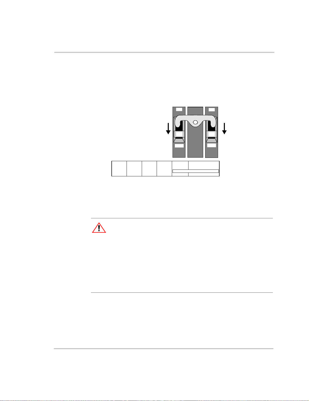
Installing Additional Breakers
If additional AC circuit breakers are to be installed for specific AC loads
or a generator disconnect, then install them per the manufacturer’s
instructions in the space to the left of the inverter bypass and AC
disconnect breakers.
Note: The ACCB DIN-Rail accepts Square-D, Type QOU
circuit breakers.
To install additional Square-D, Type QOU, circuit breakers:
1. Remove the top cover as described on page 1–11.
2. Loosen the screw in the DIN Rail End Clamp and slide the clamp to
the left to make room for the additional circuit breaker(s).
3. Install the circuit breaker(s) on the DIN rail to the left of the bypass
switch. Be sure to align them to fit into the spaces made by the
knockouts that were removed on the top cover.
4. Slide the clamp tight against the last circuit breaker on the right and
tighten the screw to secure the clamp on the DIN Rail.
Pre-installation
These factory-installed wires will be
routed and connected to the inverter.
DIN Rail
DIN Rail
End Clamp
Figure 1-9
975-0046-01-01 1–13
Installing Additional Breakers on the DIN rail
Page 26

Installation
Mounting the ACCB to the Inverter
Mounting holes
and keyhole
slots for ACCB
Important:
Ensure that the factory installed cables in the ACCB are not
pinched, crushed, removed, or damaged during the installation to the
inverter.
To install the ACCB on the inverter:
1. Mount the inverter into place, either wall-mounted or shelf-mounted,
and secure with appropriate lag bolts. See the Sine Wave Plus
Inverter/Charger Owner’s Manual for specific mounting instructions
for the inverter.
2. Line up the ACCB at the AC end of the inverter, so that the mounting
rails are aligned together and the ACCB base is as close to the
inverter as possible. The gap between the ACCB and the inverter
should be no more than 1/16 inch.
3. Secure the ACCB in place with six #10 wood screws of an
appropriate length (or lag bolts) in the six mounting and keyhole slots
on the mounting rails of the ACCB.
4. Leave the top cover off the ACCB to proceed with wire connections.
Mounting Rails
Set Inverter
OFF SRCH ON CHG
ACCB Base
with top cover
removed
Mounting holes
and keyhole
slots for ACCB
Figure 1-10
DD
Installing the ACCB on the Sine Wave Plus Inverter Charger
Sine Wave Pl us Inv ert er / Ch arg er
Sine Wave Plus Inverter/Charger
1–14 975-0046-01-01
Page 27
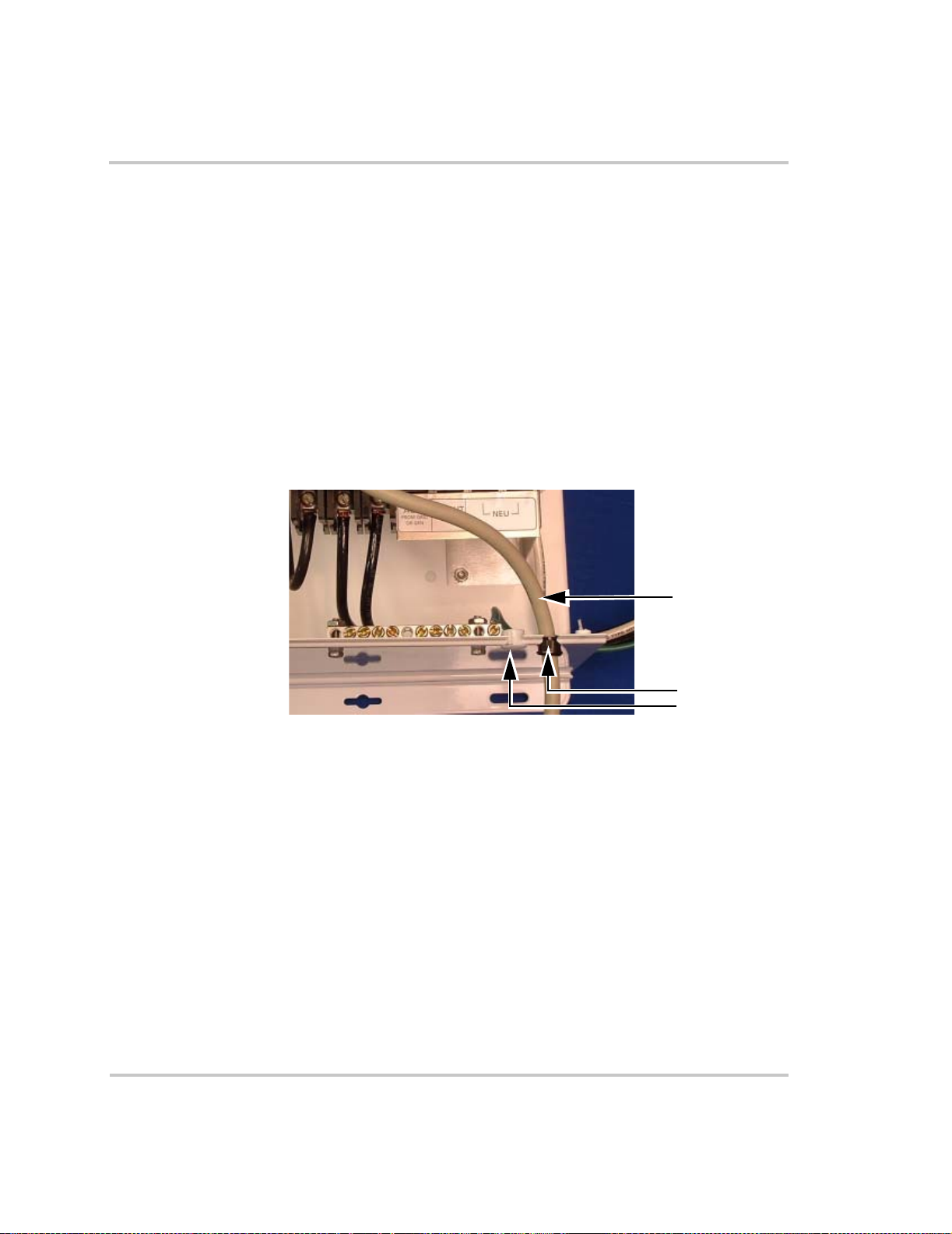
Pre-Wiring Preparation
The ACCB is pre-wired at the factory and ready for connection to the
Sine Wave Plus Inverter/Charger. The factory-installed wires are labeled
to assist with the installation procedure.
WARNING: Electrical Hazard
Do not remove or alter in any way the pre-installed factory wiring. Any changes
can result in personal injury and/or equipment damage, and will void your
warranty.
WARNING: Fire Hazard
A possible fire hazard can exist if 120 Vac only sources (such as inverters and
generators) are wired incorrectly into 120/240 Vac distribution panels containing
multiwire branch circuits.
Accessing the Terminal Blocks
Consult the Sine Wave Plus Inverter/Charger Owner’s Manual for
additional information on wire and disconnect requirements.
To prepare the ACCB and Inverter for wiring installation:
Pre-Wiring Preparation
1. Expose the terminal block in the ACCB by removing the ACCB
cover, as described on page 1–11.
2. Expose the terminal block in the inverter by removing the AC access
cover, as described in your inverter’s owner’s guide.
Wire Sizes and Disconnect Requirements
◆ Determine the wire sizes and disconnect sizes required for the
installation. See Table 1-1 for disconnects and wire sizes and Tabl e
1-2 for torque values.
Important:
Table 1-1
Full
Pass-Through
Capability
60 Amps 60 Amps #6 AWG (THHN)
975-0046-01-01 1–15
Only use copper conductors rated for 75 °C (167 °F).
AC Disconnect and Wire Sizing
Maximum
Fuse/Breaker
Required
Cable Size
Required in
Conduit
Page 28

Installation
The distribution blocks in the ACCB AC terminal block accept the
following gauge wires.
• The 1:1 distribution blocks accept #2/0 - 14 AWG.
• The 1:4 distribution blocks accept #2/0 - 14 AWG on the single
terminal and #4-14 AWG on the quad terminals.
The ground bar in the ACCB accepts #4 to 14 AWG wires.
1:1 distribution block
Figure 1-11
Table 1-2
Wire Gauge To r qu e Va lu e
14 - 10 AWG 20 lb-in
8 AWG 25 lb-in
6 - 4 AWG 36 lb-in
4 - 2/0 AWG 50 lb-in
ACCB AC Terminal Block Distribution Blocks
Torque Values for Wiring
1:4 distribution block
(x3)
WARNING: Electrical Hazard
Be sure to connect the ground wires first when connecting AC wiring to prevent
a potential shock hazard.
CAUTION: Equipment Damage
The inverter’s AC output must never be wired to the utility or generator output.
This will cause severe damage to the inverter which is not covered under
warranty.
Important:
been made and that the system ground has already been established. Consult the
Sine Wave Plus Owner’s Manual for additional wiring information.
Important:
factory-installed wiring neat and tidy so it does not interfere with airflow through
the ACCB into the Sine Wave Plus Inverter/Charger.
1–16 975-0046-01-01
These instructions assume that the DC connections have already
Be sure to use wire-ties as needed to keep field and
Page 29
Bypass Switch
Assembly
DIN Rail
Pre-Wiring Preparation
AC Terminal
Block
Factory-installed
NEUTRAL Wire
(labeled TO INV -
AC1 NEU OR
AC2 NEU)
Factory-installed Hot
OUT Wire (labeled
TO INV - OUT)
Factory-installed
Hot IN Wire
(labeled TO INV -
AC1 GRID OR
AC2 GEN)
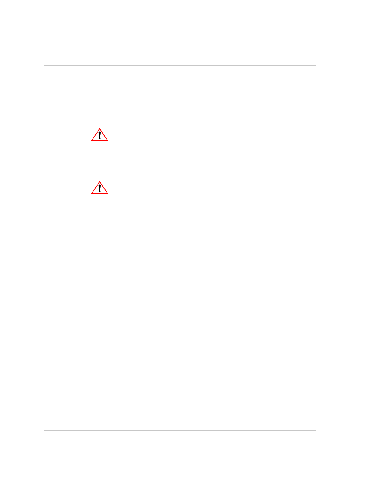
Figure 1-12
Bypass Switch
Assembly
includes: two
60-amp circuit
breakers and a
lockout rocker
Figure 1-13
ACCB Internal Components and Factory-installed Wiring
ACCB AC Terminal Block For Customer-installed Wiring
Ground Bar
NEU - Neutral In/Out
AC OUT - TO LOADS
AC IN - FROM GRID OR GEN
Factory-installed
Ground Wire
975-0046-01-01 1–17
Page 30
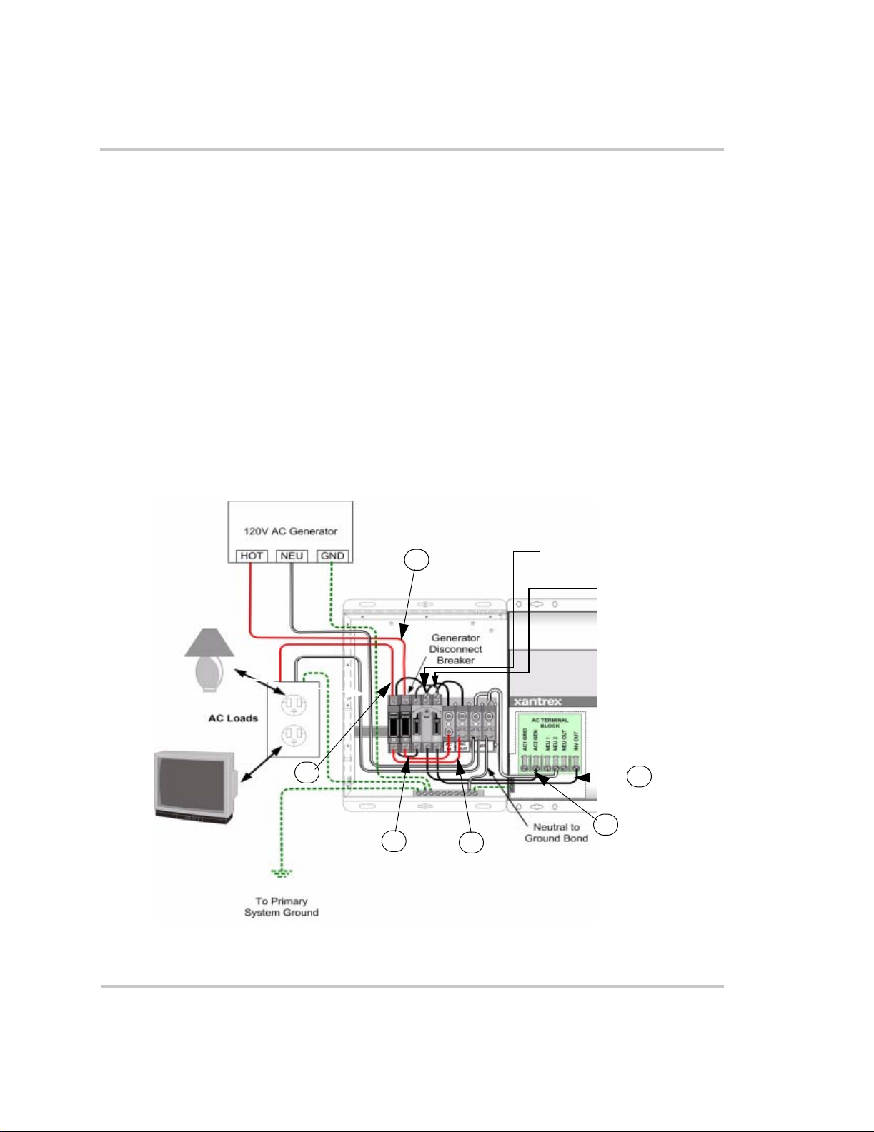
Installation
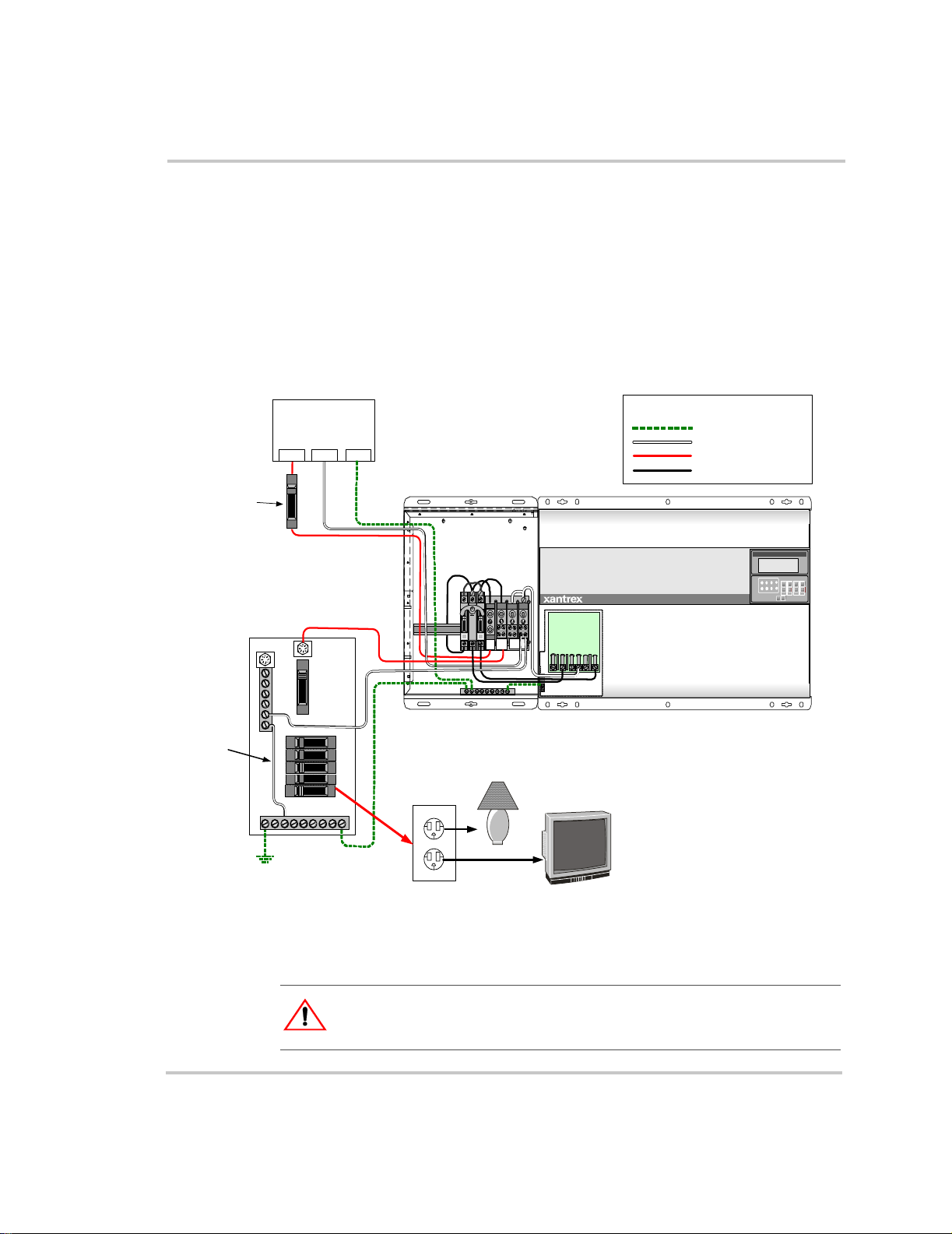
Wiring for Off-Grid Applications Using an A C Distribution
Panel and an External Generator Disconnect
The following diagram shows the complete wiring diagram for wiring the
ACCB and Sine Wave Plus Inverter inputs and outputs in an off-grid
application using an AC distribution panel for the outputs and a 120 Vac
generator for input. Wiring instructions are provided for making ground
connections first (page 1–19), neutral connections second (page 1–20),
and hot connections last (page 1–21).
LEGEND
Ground
Neutral
HOT (Owner supplied)
HOT (Factory installed)
Set Inverter
OFF SRCH ON C HG
External
Generator
Disconnect
Switch
120V AC Generator
HOT NEU GND
AC Distribution Panel
(120 Vac Only)
Neutr al to
Ground
Bond
System Ground
Figure 1-14
NEUTRAL
To Primary
Wiring an Off-Grid Application Using an AC Distribution Panel and an External
HOT
GROUND
Generator Disconnect Switch
WARNING: Shock Hazard
Ensure that all AC and DC power is not “live” before proceeding.
AC Loads
Sine Wave P lus Inverte r / Charger
AC TERMINAL
DD
ACINAC
NEU
OUT
BLOCK
INV OUT
NEU OUT
NEU 2
NEU 1
AC1 GRID
AC2 GEN
1–18 975-0046-01-01
Page 31
Wiring for Off-Grid Applications Using an AC Distribution Panel andan External Generator Disconnect
To make the ground connections:
1. Prepare the primary system ground and connect it to the ground bar in
the main AC distribution panel. See the Sine Wave Plus Inverter/
Charger Owner’s Manual for information regarding preparing the
primary system ground.
2. Route cable(s) (hot, neutral, and ground) from the AC distribution
panel through one of the knockouts prepared in the ACCB and
connect the ground wire (green) to the ground bar in the ACCB.
3. Connect the factory-installed ground wire (green) in the ACCB to the
AC ground bar in the inverter.
4. Prepare the cabling from the generator.
a) Route the hot wire (black) from the generator through a discon-
nect switch.
b) Route cable(s) (hot, neutral, and ground) from the generator and
generator disconnect switch into one of the knockouts prepared in
the ACCB. Connect the ground wire (green) from the generator
to the ground bar in the ACCB.
Figure 1-15
4a
1
Ground Connections for an Off-Grid Application with an ACDistribution Panel
4b
2
3
and an External Generator Disconnect
975-0046-01-01 1–19
Page 32

Installation
To make the neutral connections:
1. Create only one neutral-to-ground bond in the system. In this case, it
would be in the main AC distribution panel.
Important:
system. See the Sine Wave Plus Inverter/Charger Owner’s Manual for additional
information regarding the neutral-to-ground bond requirements.
Ensure there is only one neutral-to-ground bond in the entire
2. Connect the neutral (white) wire from neutral bar in the AC
distribution panel to one of the neutral terminals in the ACCB.
3. Connect the factory-installed neutral wire (white) in the ACCB to the
NEU2 terminal in the inverter.
4. Connect the neutral (white) wire from the generator and connect it to
one of the neutral terminals in the ACCB.
4
1
Figure 1-16
2
Neutral Connections for an Off-Grid Application with an AC Distribution Panel
3
and an External Generator Disconnect
1–20 975-0046-01-01
Page 33

Wiring for Off-Grid Applications Using an AC Distribution Panel andan External Generator Disconnect
To make the hot connections:
1. Connect the factory-installed hot (black) wire from the Inverter Input
Breaker in the ACCB to the AC2 GEN terminal in the inverter.
2. Connect the factory-installed hot wire (black) from the Inverter
Output Breaker in the ACCB to the INV OUT terminal in the inverter.
3. Connect a HOT (Black) wire AC OUT in the ACCB to the HOT IN in
the AC Distribution Panel.
4. Connect a hot (black) wire from the generator disconnect to the
AC IN terminal in the ACCB.
Figure 1-17
Hot Connections for an Off-grid Application with an ACDistribution Panel
and an External Generator Disconnect
4
3
1
2
975-0046-01-01 1–21
Page 34

Installation
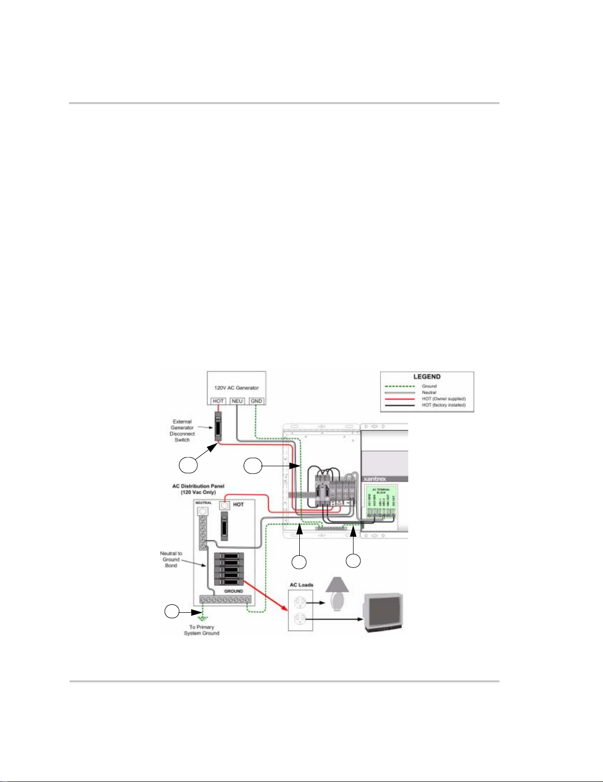
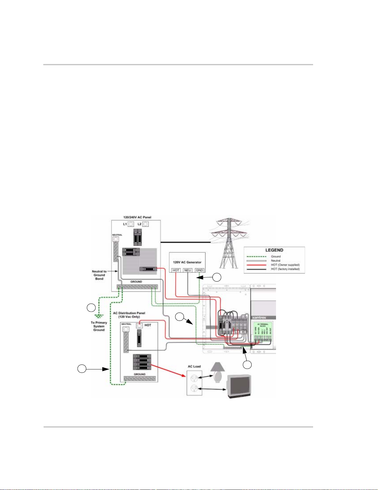
Wiring for Off-Grid Applications using an A C Distribution
Panel and an Internal Generator Disconnect
The following diagram shows the complete wiring diagram for wiring the
ACCB and Sine Wave Plus Inverter inputs and outputs in an off-grid
application using an AC distribution panel for the outputs and a 120 Vac
generator for input. This diagram also includes the use of a generator
disconnect breaker in the ACCB. Wiring instructions are provided for
making ground connections first (page 1–23), neutral connections second
(page 1–24), and hot connections last (page 1–25).
LEGEND
120V AC Generator
HOT NEU GND
AC Distributi on Panel
(120 Vac Only)
NEUT RAL
HOT
D
Generator
Disconnect
Breaker
DD
AC
AC
OUT
IN
Sine W ave Plus Inver ter / Cha rger
AC TE RM INA L
BLOCK
NEU
INV OUT
NEU OU T
NEU 2
NEU 1
AC1 GR ID
AC2 GE N
Ground
Neutr al
HOT (Owner supplied)
HOT (Factory i nstalled)
Set Inverter
OFF SRCH ON CHG
Neutral to
Ground
Bond
AC Load
GROUND
To Primary
System Ground
Figure 1-18
Wiring an Off-grid Application Using an AC Distribution Panel and an Internal
Generator Disconnect Breaker
WARNING: Shock Hazard
Ensure that all AC and DC power is not “live” before proceeding.
1–22 975-0046-01-01
Page 35

Wiring for Off-Grid Applications using an AC Distribution Panel andan Internal Generator Disconnect
To make the ground connections:
1. Prepare the primary system ground and connect it to the ground bar in
the main AC distribution panel. See the Sine Wave Plus Inverter/
Charger Owner’s Manual for information regarding preparing the
primary system ground.
2. Route cable(s) (hot, neutral, and ground) from the AC distribution
panel through one of the knockouts prepared in the ACCB and
connect the ground wire (green) to the ground bar in the ACCB.
3. Connect the factory-installed ground wire (green) in the ACCB to the
AC ground bar in the inverter.
4. Prepare the cabling from the generator. Route cable(s) (hot, neutral,
and ground) from the generator into one of the knockouts prepared in
the ACCB. Connect the ground wire (green) from the generator to the
ground bar in the ACCB.
4
Figure 1-19
2
1
Ground Connections for an Off-Grid Application with an AC Distribution P anel and
3
an Internal Generator Disconnect Breaker
975-0046-01-01 1–23
Page 36

Installation
To make the neutral connections:
1. Create only one neutral-to-ground bond in the system. In this case, it
would be in the main AC distribution panel.
Important:
system. See the Sine Wave Plus Inverter/Charger Owner’s Manual for additional
information regarding the neutral-to-ground bond requirements.
Ensure there is only one neutral-to-ground bond in the entire
2. Connect the neutral (white) wire from the neutral bar in the AC
distirbution palen to one of the neutral terminals in the ACCB.
3. Connect the factory-installed neutral wire (white) in the ACCB to the
NEU2 terminal in the inverter.
4. Connect the neutral (white) wire from the generator and connect it to
one of the neutral terminals in the ACCB.
4
1
Figure 1-20
2
Neutral Connections for an Off-Grid Application with an AC Distribution Panel and
3
an Internal Generator Disconnect
1–24 975-0046-01-01
Page 37

Wiring for Off-Grid Applications using an AC Distribution Panel andan Internal Generator Disconnect
To make the hot connections:
1. Connect the factory-installed hot (black) wire from the Inverter Input
Breaker in the ACCB to the AC2 GEN terminal in the inverter.
2. Connect the factory-installed hot wire (black) from the Inverter
Output Breaker in the ACCB to the INV OUT terminal in the inverter.
3. Connect a hot (black) wire from the AC OUT in the ACCB to the
HOT IN on the AC distribution panel.
4. Connect another hot (black) wire from the generator disconnect
breaker to the AC IN terminal in the ACCB.
5. Connect the hot (black) wire from the generator to the top of the
generator disconnect breaker.
Inverter Input Breaker
Inverter Output
Breaker
5
3
4
1
2
Figure 1-21
Hot Connections for an Off-Grid Application with an ACDistribution Panel and an
Internal Generator Disconnect
975-0046-01-01 1–25
Page 38

Installation
Wiring for Off-Grid Applications Using Additional Circuit
Breakers in the ACCB Only
The following diagram shows the complete wiring diagram for wiring the
ACCB and Sine Wave Plus Inverter inputs and outputs in an off-grid
application using additional circuit breakers in the ACCB for the outputs
and a 120 Vac generator for input. This diagram also includes the use of a
generator disconnect breaker in the ACCB. Wiring instructions are
provided for making ground connections first (page 1–27), neutral
connections second (page 1–28), and hot connections last (page 1–29).
LEGEND
120V AC G enerator
HOT NEU GND
Additional AC Load
Circuit Breaker
Generator
Disconnect
Breaker
Ground
Neut ral
HOT (Owner supplied)
HOT (Factory installed)
Set Inverter
OFF SRCH ON CHG
Sine Wa ve Plu s Inv erter / Ch arge r
AC Loads
Figure 1-22
DD
D
D
To P rim a ry
System Ground
AC
AC
NEU
OUT
IN
Wiring an Off-Grid Application Using Additional Circuit Breakers in the ACCB Only
AC TE RM INA L
BLOCK
NEU OUT
NEU 2
NEU 1
AC1 GRID
AC2 GEN
Neutral to
Ground Bond
INV OUT
WARNING: Shock Hazard
Ensure that all AC and DC power is not “live” before proceeding.
1–26 975-0046-01-01
Page 39

Wiring for Off-Grid Applications Using Additional Circuit Breakers inthe ACCB Only
To make the ground connections:
1. Prepare the primary system ground and, routing it through one of the
knockouts prepared in the ACCB, connect it to the ground bar in the
ACCB. See the Sine Wave Plus Inverter/Charger Owner’s Manual for
information regarding preparing the primary system ground.
2. Connect the factory-installed ground wire (green) in the ACCB to the
AC ground bar in the inverter.
3. Prepare the cabling from the generator. Route cable(s) (hot, neutral,
and ground) from the generator into one of the knockouts prepared in
the ACCB. Connect the ground wire (green) from the generator to the
ground bar in the ACCB.
4. Route and connect a ground wire from the ground bar in the ACCB to
the outlet that will support the AC load.
3
4
Figure 1-23
1
Ground Connections for an Off-Grid Application with Additional Circuit Breakers
2
in the ACCB
975-0046-01-01 1–27
Page 40

Installation
To make the neutral connections:
1. Create only one neutral-to-ground bond in the system. In this case, it
would be in the ACCB.
Important:
system. See the Sine Wave Plus Inverter/Charger Owner’s Manual for additional
information regarding the neutral-to-ground bond requirements.
Ensure there is only one neutral-to-ground bond in the entire
2. Connect the factory-installed neutral wire (white) in the ACCB to the
NEU2 terminal in the inverter.
3. Connect the neutral (white) wire from the generator (or generator
disconnect) and connect it to one of the neutral terminals in the
ACCB.
4. Route and connect a neutral wire from one of the neutral connections
in the ACCB to the outlet that will support the AC load.
3
4
2
1
Figure 1-24
Neutral Connections for an Off-grid Application with Additional Circuit
Breakersin the ACCB
1–28 975-0046-01-01
Page 41
Wiring for Off-Grid Applications Using Additional Circuit Breakers inthe ACCB Only
To make the hot connections:
1. Connect the factory-installed hot (black) wire from the Inverter Input
Breaker in the ACCB to the AC2 GEN terminal in the inverter
2. Connect the factory-installed hot wire (black) from the Inverter
Output Breaker in the ACCB to the INV OUT terminal in the inverter.
3. Connect another hot (black) wire from the generator disconnect
breaker to the AC IN terminal in the ACCB. Connect the other end of
that same hot (black) wire to the bottom of the generator disconnect
breaker.
4. Connect another hot (black) wire from the AC OUT terminal in the
ACCB to the bottom of the new circuit breaker.
5. Connect the hot (black) wire from the generator to the top of the
generator disconnect breaker.
6. Connect another hot (black) wire from the top of the additional circuit
breaker to the outlet that will support the AC load.
Figure 1-25
in the ACCB
5
6
3
4
Inverter Input
Breaker
Inverter Output
Breaker
2
1
Hot Connections for an Off-grid Application with Additional Circuit Breakers
975-0046-01-01 1–29
Page 42

Installation
Wiring for On-Grid Applications Using an AC Distribution
Panel and an Internal Generator Disconnect Breaker
The following diagram shows the complete wiring diagram for wiring the
ACCB and Sine Wave Plus Inverter inputs and outputs in an on-grid
application using an AC distribution panel for the outputs and a 120 Vac
generator for input. This diagram also uses an internal generator
disconnect breaker in the ACCB. Wiring instructions are provided for
making ground connections first (page 1–31), neutral connections second
(page 1–32), and hot connections last (page 1–33).
Figure 1-26
120/240V AC Panel
L1 L2
NEUTR AL
120V AC G enerator
Neutra l to
Ground
Bond
To Prim ary
System
Ground
GROUND
AC D istr ibuti on P anel
(120 Vac Only)
NEUTRAL
GROUND
HOT
HOT NEU GND
AC Load
AC TERMINAL
DD
D
AC
AC
OUT
IN
BLOC K
NEU
NEU 2
NEU 1
AC1 G RID
AC2 G EN
Sine Wave Pl us Invert er / Ch arger
INV OUT
NEU OUT
Wiring an On-grid Application USING an AC Distribution Panel
LEGEND
Ground
Neutral
HOT (Owner supplied)
HOT (Factory installed)
Set Inverter
OFF SRCH ON CHG
WARNING: Shock Hazard
Ensure that all AC and DC power is not “live” before proceeding.
Important:
and work with, a single AC source. In a system that has multiple AC sources, you
must decide which AC source will be wired through the inverter bypass circuit
breaker and which will not. The following illustrations assume that the primary
AC input source will be the utility grid.
1–30 975-0046-01-01
The inverter bypass circuit breaker can only be wired directly to,
Page 43
Main AC Distribution
Panel
Wiring for On-Grid Applications Using an AC Distribution P anel
To make the ground connections:
1. Prepare the primary system ground and connect it to the ground bar in
the main AC distribution panel. See the Sine Wave Plus Inverter/
Charger Owner’s Manual for information regarding preparing the
primary system ground.
2. Connect a ground wire (green) from the main AC distribution panel
to the ground bar in the sub panel.
3. Route cable(s) (hot, neutral, and ground) from the main AC
distribution panel through one of the knockouts prepared in the
ACCB and connect the ground wire (green) to the ground bar in the
ACCB.
4. Connect the factory-installed ground wire (green) in the ACCB to the
AC ground bar in the inverter.
5. Connect the ground wire (green) from the generator to the ground bar
in the main AC distribution panel.
5
1
3
SubPanel
4
Figure 1-27
2
Ground Connections for an On-Grid Application with an AC Distribution P anel (sub
panel) and a Generator Disconnect Breaker in the ACCB
975-0046-01-01 1–31
Page 44

Installation
To make the neutral connections:
1. Ensure there is only one neutral-to-ground bond in the system. In this
case, it would be in the main AC distribution panel.
Main AC Distribution
Panel
1
Important:
system. See the Sine Wave Plus Inverter/Charger Owner’s Manual for additional
information regarding the neutral-to-ground bond requirements.
Ensure there is only one neutral-to-ground bond in the entire
2. Connect the neutral (white) wire from the neutral bar in the main AC
distribution panel to one of the neutral terminals in the ACCB.
3. Connect a neutral (white) wire from the sub panel to one of the
neutral terminals in the ACCB.
4. Connect the factory-installed neutral wire (white) in the ACCB to the
NEU1 terminal in the inverter.
5. Connect the neutral (white) wire from the generator (or generator
disconnect) and connect it to one of the neutral terminals in the
ACCB.
2
5
3
4
Figure 1-28
SubPanel
Neutral Connections for an On-grid Application with an AC Distribution Panel and
internal Generator Disconnect Breaker in the ACCB
1–32 975-0046-01-01
Page 45

Main AC
Distribution
Panel
Wiring for On-Grid Applications Using an AC Distribution P anel
To make the hot connections:
1. Connect the factory-installed hot (black) wire from the Inverter Input
Breaker in the ACCB to the AC1 GRID terminal in the inverter
2. Connect the factory-installed hot wire (black) from the Inverter
Output Breaker in the ACCB to the INV OUT terminal in the inverter.
3. Connect the hot (black) wire from the main AC distribution panel to
the AC IN terminal in the ACCB.
4. Connect the hot (black) wire from the generator to the top of the
generator disconnect breaker in the ACCB.
5. Connect another hot (black) wire from the bottom of that same
generator disconnect breaker in the ACCB to the AC2 GEN terminal.
6. Connect a hot (black) wire from the AC OUT terminal in the ACCB
to the sub panel.
Generator
Disconnect Breaker
Inverter Input Breaker
SubPanel
Figure 1-29
4
3
6
1
Hot Connections for an On-Grid Application with an AC Distribution Panel and an
Inverter Output Breaker
5
2
Internal Generator Disconnect
975-0046-01-01 1–33
Page 46

Installation
Wiring for On-Grid Applications Using Additional Circuit
Breakers in the ACCB Only
The following diagram shows the complete wiring diagram for wiring the
ACCB and Sine Wave Plus Inverter inputs and outputs in an on-grid
application using an AC distribution panel for the outputs and a 120 Vac
generator for input. This diagram also uses an internal generator
disconnect breaker in the ACCB. Wiring instructions are provided for
making ground connections first (page 1–35), neutral connections second
(page 1–36), and hot connections last (page 1–37).
NEUT RAL
Neut ral t o
Ground
Bond
To Primary
System
Groun d
Figure 1-30
120/240V AC Panel
L1 L2
GROUND
AC Load
120V AC Generator
HOT NEU GN D
DD
Generator
Disconnect
Breaker
DD
Additional AC Load
Circuit Breaker
AC
AC
NEU
OUT
IN
AC TERMINAL
BLOCK
AC1 GRID
AC2 GEN
INV OUT
NEU OUT
NEU 2
NEU 1
LEGEND
Ground
Neut ral
HOT (Owner supplied)
HOT (Fac tory inst all ed)
Sine Wave Plus Inverter / Charger
Set Inverter
OFF SRCH ON CHG
Wiring an On-Grid Application Using Additional Circuit Breakers in the ACCB Only
WARNING: Shock Hazard
Ensure that all AC and DC power is not “live” before proceeding.
Important:
and work with, a single AC source. In a system that has multiple AC sources, you
must decide which AC source will be wired through the inverter bypass circuit
breaker and which will not. The following illustrations assume that the primary
AC input source will be the utility grid.
1–34 975-0046-01-01
The inverter bypass circuit breaker can only be wired directly to,
Page 47

Wiring for On-Grid Applications Using Additional Circuit Breakers inthe ACCB Only
To make the ground connections:
1. Prepare the primary system ground and connect it to the ground bar in
the main AC distribution panel. See the Sine Wave Plus Inverter/
Charger Owner’s Manual for information regarding preparing the
primary system ground.
2. Route cable(s) (hot, neutral, and ground) from the main AC
distribution panel through one of the knockouts prepared in the
ACCB and connect the ground wire (green) to the ground bar in the
ACCB.
3. Connect the factory-installed ground wire (green) in the ACCB to the
AC ground bar in the inverter.
4. Connect the ground wire (green) from the generator to the ground bar
in the main AC distribution panel.
5. Route and connect a ground wire to the outlet that will be supporting
the AC load.
4
2
1
3
Figure 1-31
5
Ground Connections for an On-grid Application Using Additional Circuit Breakers
in the ACCB Only
975-0046-01-01 1–35
Page 48

Installation
To make the neutral connections:
1. Ensure there is only one neutral-to-ground bond in the system. In this
case, it would be in the main AC distribution panel.
Important:
system. See the Sine Wave Plus Inverter/Charger Owner’s Manual for additional
information regarding the neutral-to-ground bond requirements.
Ensure there is only one neutral-to-ground bond in the entire
2. Connect the neutral (white) wire from the neutral bar in the main AC
distribution panel to one of the neutral terminals in the ACCB.
3. Connect the factory-installed neutral wire (white) in the ACCB to the
NEU1 terminal in the inverter.
4. Connect the neutral (white) wire from the generator and connect it to
one of the neutral terminals in the ACCB.
5. Route and connect a neutral (white) wire from one of the neutral
terminals in the ACCB to the outlet that will be supporting the
AC load.
1
4
2
3
5
Figure 1-32
Neutral Connections for an On-Grid Application Using Additional Circuit Breakers
in the ACCB Only
1–36 975-0046-01-01
Page 49

Wiring for On-Grid Applications Using Additional Circuit Breakers inthe ACCB Only
To make the hot connections:
1. Connect the factory-installed hot (black) wire from the Inverter Input
Breaker in the ACCB to the AC1 GRID terminal in the inverter
2. Connect the factory-installed hot wire (black) from the Inverter
Output Breaker in the ACCB to the INV OUT terminal in the inverter.
3. Connect the hot (black) wire from the main AC distribution panel to
the AC IN terminal in the ACCB.
4. Connect the hot (black) wire from the generator to the top of the
generator disconnect breaker in the ACCB.
5. Connect another hot (black) wire from the bottom of that same
generator disconnect breaker in the ACCB to the AC2 GEN terminal.
6. Connect a hot (black) wire from the AC OUT terminal in the ACCB
to the bottom of the additional circuit breaker installed in the ACCB
7. Connect another hot (black) wire from the top of that same additional
circuit breaker in the ACCB and route to the outlet that will be
supporting the AC load.
4
3
7
Figure 1-33
Additional AC Load
Circuit Breaker
5
6
Hot Connections for an On-Grid Application Using Additional Circuit Breakers in
2
1
the ACCB Only
975-0046-01-01 1–37
Page 50

Installation
Additional Accessory Wiring
If you have any of the following accessories connected (or to be
connected) to your inverter, then you will also need to pass their
connecting cables through the ACCB to the AC side of the inverter:
• Generator Start Module (GSM) for automatic generator control
• Auxiliary Load Module (ALM) for controlling auxiliary loads such as
alarms, water pumps or ventilator fans
• Emergency Power Off (EPO) switch, Inverter Control Module (ICM),
or an Inverter Communications Adapter (ICA) for remote control and
monitoring of the inverter
• Inverter Stacking Control – Series (ISC-S) Cable for connecting to
another inverter in a dual inverter configuration.
See your inverter owner’s guide and the appropriate accessory guide for
further information about the installation and configuration of these
accessories.
1–38 975-0046-01-01
Page 51
Wiring for Dual Inverter Configurations
Wiring for Dual Inverter Configurations
Series stacked Sine Wave Plus inverters with ACCBs installed are wired
essentially the same as single inverters, with the following differences.
Installing the ISC-S Cable
The ISC-S cable must be run through one of the ISC-S/ICM cable slots
provided on the sides of the ACCB (see Figure 1-7 on page 1–10). The
cable slots are blocked with hole plugs. These hole plugs must be
removed before inserting the ISC-S cable.
Remove the hole plug for the slot to be used by the cable only. Do not
remove any other hole plugs. Ensure that the all the other hole plugs are
still in place as shown in Figure 1-34).
ISC-S Cable
Grommet
Hole Plug
Figure 1-34
ISC-S Cable in an ISC-S/ICM Cable Slot of the ACCB
AC Neutral Wiring for Dual Configurations
All of the AC wiring for dual Sine Wave Plus inverters remains the same,
except for two changes in the neutral wiring:
1. All NEUTRAL IN wiring goes only to the neutral terminals in the L1
ACCB (attached to the L1 Sine Wave Plus inverter).
2. A neutral bond between the inverters is created by connecting an
owner supplied #6 AWG THHN neutral wire (white) from the ACCB
neutral terminal attached to the L1 Sine Wave Plus inverter to the
ACCB neutral terminal attached to the L2 Sine Wave Plus inverter.
This wire should be long enough to pass from the L2 inverter AC
terminal block, through adjacent knockouts on both ACCBs, to the
L1 inverter ACCB terminal block.
975-0046-01-01 1–39
Page 52

Installation
Installing the Safety Plate
The purpose of the Safety Plate (SP-1) is to prevent accidental contact
with any live circuits or wires within the AC Conduit Box. The Safety
Plate only needs to be installed in the event that the Sine Wave Plus is
removed. The Safety Plate (SP-1) covers the open end of AC Conduit
Box on the inverter side. It attaches to the base of the conduit box and is
secured by the Sems screws that attach the top cover.
WARNING: Shock Hazard
Be sure to disconnect all DC and AC power before removing the
inverter and installing the safety plate.
To install the safety plate:
3. Remove the two #8 Sems screws on the top and bottom of the ACCB.
Put these screws is a safe place.
4. Slide the safety plate over the open end of the conduit box inserting
the cover tabs into the slots on the safety plate. Be sure to align the
holes for the screws for resecuring the top cover.
5. Replace the two #8 Sems screws on the top and bottom of the chassis
to secure the Safety Plate into place.
Remove these 2
#8 Sems Screws only
Cover Tabs
Inverter side
of ACCB
Figure 1-35
1–40 975-0046-01-01
Removing the Sems Screws From the ACCB Top Cover
Page 53

Top Cover
Installing the Safety Plate
A
C
C
o
n
d
u
i
t
B
o
x
Safety Plate
Ensure the top cover tabs
protrude through the
cover tab slots.
Replace the #8
Sems screw from
A
C
C
o
n
d
u
t
i
B
o
x
the top of the
chassis.
Replace the #8 Sems
screw from the bottom
of the chassis.
Figure 1-36
Installing the Safety Plate SP-1 on the ACCB
975-0046-01-01 1–41
Page 54

1–42
Page 55

2
Operating the ACCB
Chapter 2, “Operating the ACCB” describes the different
modes and operation of the Bypass Switch on the ACCB.
The following topics are covered in this chapter.
For this topic: See:
“The Bypass Switch” page 2–2
“Operating the Bypass Switch” page 2–2
“Dual Inverters: 240 Vac Loads” page 2–4
Page 56

Operating the ACCB
The Bypass Switch
During normal operation (Figure 2-2 on page 2–3), AC power passes
from the external AC source (generator or grid) through the inverter to the
AC loads. The inverter monitors the incoming power and can keep the
batteries charged.
When external sources of AC power are not available, the inverter
switches to external DC power (e.g., batteries, generator, solar, wind,
hydro fuel cell) and continues to power the load.
When performing inverter maintenance, the breakers can be switched to
the Bypass Operation (Figure 2-3 on page 2–3) which allows the AC
loads to be powered directly from the the external AC source without
affecting connected AC loads.
To de-energize both circuits, switch the breaker pair to the OFF position
(Figure 2-4 on page 2–4).
Operating the Bypass Switch
Once the AC voltage has been applied, the bypass switch is ready for
operation. Under normal operation the Inverter Output breaker is ON.
There are three possible modes of operation for the bypass switch:
• “Normal Operation”
• “Bypass Operation”
• “AC Input/Output Off”.
ON
60
OFF
INVERTER
BYPASS
BOTH OFF TO DISCONNECT AC OUTPUT
NORMAL OPERATION:
Left Breaker = ON
Right Breaker = OFF
Inverter AC power
available to Inverter
AC Distribution Panel
Figure 2-1
ON
60
OFF
INVERTER
DISCONNECT
Bypass Switch Mode Summary
ON
60
OFF
INVERTER
BYPASS
BOTH OFF TO DISCONNECT AC OUTPUT
BYPASS OPERATION:
Left Breaker = OFF
Right Breaker = ON
Utility or Generator AC
power available to Inverter
AC Distribution Panel
ON
OFF
INVERTER
DISCONNECT
60
2–2 975-0046-01-01
ON
60
OFF
INVERT ER
BYPASS
BOTH OFF TO DISCONNECT AC OUTPUT
AC O FF OPERATION :
Left Breaker = OFF
Right Breaker = OFF
Utility/Generator/Inverter AC
power disconnected to
Inverter AC Distribution Panel
ON
OFF
INVERTER
DISCONNECT
60
Page 57

Normal Operation
‘
Operating the Bypass Switch
Inverter AC power passes through the inverter to the load (Figure 2-2).
In this configuration, power passes through the inverter to the connected
load. When external AC power is not available, power from the external
DC source is used by the inverter to power the AC loads.
Bypass Operation
‘
Inverter in Circuit
Figure 2-2
INVERTER
1234
Normal Operation
ON
60
OFF
BYPASS
BOTH OFF TO DISCONNECT AC OUTPU T
ON
60
OFF
INVERTER
DISCONNECT
External AC power routed directly to the AC loads (Figure 2-3).
In this configuration, power passes directly to the connected load,
bypassing the inverter. This allows the inverter to be removed from
service without affecting the connected load. If the extenal source of AC
becomes unavailable while the Bypass Operation is selected, the load will
be dropped.
Inverter out of Circuit
Figure 2-3
1234
Bypass Operation
ON
60
OFF
INVERTER
BYPASS
BOTH OFF TO DISCONNECT AC OUTPUT
ON
OFF
INVERTER
DISCONNECT
60
975-0046-01-01 2–3
Page 58
Operating the ACCB
AC Input/Output Off
No power to the load or charger (Figure 2-4).
In this configuration, power from both the external sources of AC and the
inverter is removed from the loads. This allows the inverter, the connected
loads, or any other installed equipment beyond the ACCB to be serviced.
‘
Both external AC
source and Inverter OFF
AC Input
from Grid or Gen
Figure 2-4
AC Output OFF
Dual Inverters: 240 Vac Loads
WARNING: Fire Hazard
In a series-stacked, inverter installation (120/240 Vac) with a bypass switch for
each inverter, both bypass switches must be in the same position.
If the bypass switches are not in the same position, the resulting AC output of the
two bypass switches may not be 180° out-of-phase from each other. This can
result in excess current on the neutral wire creating a potential fire hazard.
ON
60 60
OFF
INVERTER
BYPASS
BOTH OFF TO DISCONNECT AC OUTPU T
1234
INVERTER
DISCONNECT
ON
OFF
AC Output
to Loads
This can also result in less than 240 Vac output. Loads requiring 240 Vac will not
run.
2–4 975-0046-01-01
Page 59

Warranty and Product
Information
Warranty
What does this warranty cover? This Limited Warranty is provided by Xantrex Technology, Inc.
("Xantrex") and covers defects in workmanship and materials in your Sine Wave Plus AC Conduit Box. This
warranty lasts for a Warranty Period of two (2) years from the date of purchase at point of sale to you, the
original end user customer.
This Limited Warranty is transferable to subsequent owners but only for the unexpired portion of the Warranty
Period.
What will Xantrex do? Xantrex will, at its option, repair or replace the defective product free of charge,
provided that you notify Xantrex of the product defect within the Warranty Period, and provided that Xantrex
through inspection establishes the existence of such a defect and that it is covered by this Limited Warranty.
Xantrex will, at its option, use new and/or reconditioned parts in performing warranty repair and building
replacement products. Xantrex reserves the right to use parts or products of original or improved design in the
repair or replacement. If Xantrex repairs or replaces a product, its warranty continues for the remaining
portion of the original Warranty Period or 90 days from the date of the return shipment to the customer,
whichever is greater. All replaced products and all parts removed from repaired products become the property
of Xantrex.
Xantrex covers both parts and labor necessary to repair the product, and return shipment to the customer via a
Xantrex-selected non-expedited surface freight within the contiguous United States and Canada. Alaska and
Hawaii are excluded. Contact Xantrex Customer Service for details on freight policy for return shipments
outside of the contiguous United States and Canada.
How do you get service? If your product requires troubleshooting or warranty service, contact your
merchant. If you are unable to contact your merchant, or the merchant is unable to provide service, contact
Xantrex directly at:
Phone: 1-800-670-0707 (toll free)
1-360-435-8826 (direct)
Fax: 1-360-435-3547
Email: CustomerService@xantrex.com
Direct returns may be performed according to the Xantrex Return Material Authorization Policy described in
your product manual. For some products, Xantrex maintains a network of regional Authorized Service
Centers. Call Xantrex or check our website to see if your product can be repaired at one of these facilities.
In any warranty claim, dated proof of purchase must accompany the product and the product must not have
been disassembled or modified without prior written authorization by Xantrex.
975-0046-01-01 WA–1
Page 60

Warranty and Product Information
Proof of purchase may be in any one of the following forms:
• The dated purchase receipt from the original purchase of the product at point of sale to the end user, or
• The dated dealer invoice or purchase receipt showing original equipment manufacturer (OEM) status, or
• The dated invoice or purchase receipt showing the product exchanged under warranty
What does this warranty not cover? This Limited Warranty does not cover normal wear and tear of the
product or costs related to the removal, installation, or troubleshooting of the customer's electrical systems.
This warranty does not apply to and Xantrex will not be responsible for any defect in or damage to:
a) the product if it has been misused, neglected, improperly installed, physically damaged or altered, either
internally or externally, or damaged from improper use or use in an unsuitable environment;
b) the product if it has been subjected to fire, water, generalized corrosion, biological infestations, or input
voltage that creates operating conditions beyond the maximum or minimum limits listed in the Xantrex
product specifications including high input voltage from generators and lightning strikes;
c) the product if repairs have been done to it other than by Xantrex or its authorized service centers (hereaf-
ter "ASCs");
d) the product if it is used as a component part of a product expressly warranted by another manufacturer;
e) the product if its original identification (trade-mark, serial number) markings have been defaced, altered,
or removed.
Disclaimer
Product
THIS LIMITED WARRANTY IS THE SOLE AND EXCLUSIVE WARRANTY PROVIDED BY XANTREX IN CONNECTION
WITH YOUR XANTREX PRODUCT AND IS, WHERE PERMITTED BY LAW, IN LIEU OF ALL OTHER WARRANTIES,
CONDITIONS, GUARANTEES, REPRESENTATIONS, OBLIGATIONS AND LIABILITIES, EXPRESS OR IMPLIED,
STATUTORY OR OTHERWISE IN CONNECTION WITH THE PRODUCT, HOWEVER ARISING (WHETHER BY CONTRACT,
TORT, NEGLIGENCE, PRINCIPLES OF MANUFACTURER'S LIABILITY, OPERATION OF LAW, CONDUCT, STATEMENT OR
OTHERWISE), INCLUDING WITHOUT RESTRICTION ANY IMPLIED WARRANTY OR CONDITION OF QUALITY,
MERCHANTABILITY OR FITNESS FOR A PARTICULAR PURPOSE. ANY IMPLIED WARRANTY OF MERCHANTABILITY
OR FITNESS FOR A PARTICULAR PURPOSE TO THE EXTENT REQUIRED UNDER APPLICABLE LAW TO APPLY TO THE
PRODUCT SHALL BE LIMITED IN DURATION TO THE PERIOD STIPULATED UNDER THIS LIMITED WARRANTY.
IN NO EVENT WILL XANTREX BE LIABLE FOR ANY SPECIAL, DIRECT, INDIRECT, INCIDENTAL OR CONSEQUENTIAL
DAMAGES, LOSSES, COSTS OR EXPENSES HOWEVER ARISING WHETHER IN CONTRACT OR TORT INCLUDING
WITHOUT RESTRICTION ANY ECONOMIC LOSSES OF ANY KIND, ANY LOSS OR DAMAGE TO PROPERTY, ANY
PERSONAL INJURY, ANY DAMAGE OR INJURY ARISING FROM OR AS A RESULT OF MISUSE OR ABUSE, OR THE
INCORRECT INSTALLATION, INTEGRATION OR OPERATION OF THE PRODUCT.
Exclusions
If this product is a consumer product, federal law does not allow an exclusion of implied warranties. To the
extent you are entitled to implied warranties under federal law, to the extent permitted by applicable law they
are limited to the duration of this Limited Warranty. Some states and provinces do not allow limitations or
exclusions on implied warranties or on the duration of an implied warranty or on the limitation or exclusion of
incidental or consequential damages, so the above limitation(s) or exclusion(s) may not apply to you. This
Limited Warranty gives you specific legal rights. You may have other rights which may vary from state to
state or province to province.
WA–2 975-0046-01-01
Page 61

Return Material Authorization Policy
Warning: Limitations On Use
Please refer to your product manual for limitations on uses of the product.
SPECIFICALLY, PLEASE NOTE THAT THE SINE WAVE PLUS AC CONDUIT BOX SHOULD NOT BE USED IN CONNECTION
WITH LIFE SUPPORT SYSTEMS OR OTHER MEDICAL EQUIPMENT OR DEVICES. WITHOUT LIMITING THE GENERALITY
OF THE FOREGOING, XANTREX MAKES NO REPRESENTATIONS OR WARRANTIES REGARDING THE USE OF THE
XANTREX SINE WAVE PLUS AC CONDUIT BOX IN CONNECTION WITH LIFE SUPPORT SYSTEMS OR OTHER MEDICAL
EQUIPMENT OR DEVICES.
Please note that the Sine Wave Plus AC Conduit Box is not intended for use as an uninterruptible power
supply and Xantrex makes no warranty or representation in connection with any use of the product for such
purposes.
Return Material Authorization Policy
Before returning a product directly to Xantrex you must obtain a Return Material Authorization (RMA)
number and the correct factory "Ship To" address. Products must also be shipped prepaid. Product shipments
will be refused and returned at your expense if they are unauthorized, returned without an RMA number
clearly marked on the outside of the shipping box, if they are shipped collect, or if they are shipped to the
wrong location.
When you contact Xantrex to obtain service, please have your instruction manual ready for reference and be
prepared to supply:
• The serial number of your product
• Information about the installation and use of the unit
• Information about the failure and/or reason for the return
• A copy of your dated proof of purchase
Record these details in on page WA–4.
Return Procedure
1. Package the unit safely, preferably using the original box and packing materials. Please ensure that your
product is shipped fully insured in the original packaging or equivalent. This warranty will not apply
where the product is damaged due to improper packaging.
2. Include the following:
• The RMA number supplied by Xantrex Technology, Inc. clearly marked on the outside of the box.
• A return address where the unit can be shipped. Post office boxes are not acceptable.
• A contact telephone number where you can be reached during work hours.
• A brief description of the problem.
3. Ship the unit prepaid to the address provided by your Xantrex customer service representative.
If you are returning a product from outside of the USA or Canada In addition to the above, you
MUST include return freight funds and are fully responsible for all documents, duties, tariffs, and deposits.
If you are returning a product to a Xantrex Authorized Service Center (ASC) A Xantrex return
material authorization (RMA) number is not required. However, you must contact the ASC prior to returning
the product or presenting the unit to verify any return procedures that may apply to that particular facility.
975-0046-01-01 WA–3
Page 62

Warranty and Product Information
Out of Warranty Service
If the warranty period for your Sine Wave Plus AC Conduit Box has expired, if the unit was damaged by
misuse or incorrect installation, if other conditions of the warranty have not been met, or if no dated proof of
purchase is available, your inverter may be serviced or replaced for a flat fee.
To return your Sine Wave Plus AC Conduit Box for out of warranty service, contact Xantrex Customer
Service for a Return Material Authorization (RMA) number and follow the other steps outlined in “Return
Procedure” on page WA–3.
Payment options such as credit card or money order will be explained by the Customer Service
Representative. In cases where the minimum flat fee does not apply, as with incomplete units or units with
excessive damage, an additional fee will be charged. If applicable, you will be contacted by Customer Service
once your unit has been received.
Information About Your System
As soon as you open your Sine Wave Plus AC Conduit Box package, record the following information and be
sure to keep your proof of purchase.
❐ Purchased From
❐ Purchase Date
_________________________________
_________________________________
WA–4 975-0046-01-01
Page 63

Index
A
abbreviations and acronyms iv
AC conduit box (ACCB)
introduction
specifications 1–3
AC load breakers 1–13
AC wiring for dual inverters 1–39
additional accessory wiring 1–38
additional breakers in the ACCB 1–13
Auxiliary Load Module (ALM), wiring for 1–38
1–2
B
breakers 1–3
DIN-rail 1–13
owner-installed 1–13
bypass switch 1–4
AC output OFF 2–4
bypass operation 2–3
normal operation 2–3
C
Customer Service
email
WA–1
fax number WA–1
phone number WA–1
I
Information about Your System form WA–4
installation
additional breakers in ACCB
codes 1–5
knockout preparation 1–8
materials 1–5
removing cover 1–12
tools 1–5
inverter
purchase date
Inverter Communications Adapter (ICA), wiring for
Inverter Control Module (ICM), wiring for 1–38
Inverter Stacking Control - Series (ISC-S) cable
ACCB slots for
additional accessory wiring 1–38
grommets for ACCB slots 1–12
install for dual inverters 1–39
ISC-S/ICM cable slots 1–12, 1–39
WA–4
1–38
1–10
1–13
K
knockouts
location on the ACCB
location on the inverter 1–8
preparation 1–8
1–10
D
DIN-rail 1–13
dual inverters
wiring for
1–39
E
email, contacting Customer Service by WA–1
Emergency Power Off (EPO), wiring for 1–38
F
fax number for Customer Service WA–1
G
Generator Start Module (GSM), wiring for 1–38
M
materials required for installation 1–5
N
neutral bond for dual inverters 1–39
O
operation of bypass switch 2–2
P
preparation for installation 1–2
proof of purchase WA–4
purchase date WA–4
Page 64

Index
R
return material authorization (RMA) policy WA–3
return procedure under warranty WA–3
RMA number WA–4
S
safety instructions v–vi
Safety Plate (SP-1) 1–40
series stacked inverters, see dual inverters
specifications for the ACCB 1–3
T
telephone number for Customer Service WA–1
tools required for installation 1–5
W
warranty
out of warranty service
return material authorization policy WA–3
return under warranty WA–3
terms and conditions WA–1
wiring
additional accessories
grounding the ACCB 1–19, 1–20, 1–21, 1–23,
1–24, 1–25, 1–27, 1–28, 1–29, 1–31,
1–32, 1–33, 1–35, 1–36, 1–37
WA–4
1–38
X
Xantrex
Authorized Service Center (ASC)
3
Customer Service WA–1, WA–4
web site iv
IX–2 975-0046-01-01
WA–1, WA–
Page 65

Page 66

Xantrex Technology Inc.
360 435 8826 Tel
360 435 3547 Fax
800 670 0707 Toll Free North America
customerservice@xantrex.com
www.xantrex.com
975-0046-01-01
Printed in usa
 Loading...