

Page 1
Xantrex Technology Inc.
1 800 670 0707 Tel toll free NA
1 360 925 5097 Tel direct
1 800 994 7828 Fax toll free NA
1 360 925 5143 Fax direct
customerservice@xantrex.com
www.xantrex.com
975-0264-01-01 Rev A
PC Printed USA
RC8 Remote
Control
M
RC8
Installation and Operations
Guide
Page 2

Page 3
RC8 Remote Control
Installation and Operations
Guide
Warranty and Return
20 975-0264-01-01 Rev A
Information About Your System
As soon as you open your RC8 Remote Control package, record the following information
and be sure to keep your proof of purchase.
If you need to contact Customer Service, please record the following details before
calling. This information will help our representatives give you better service.
❐ Serial Number (on DC end)
_______________________________
❐ Purchased From
_______________________________
❐ Purchase Date
_______________________________
❐ Type of installation [e.g.
RV, truck, vehicle, home]
_________________________________
❐ Length of time inverter has
been installed
_________________________________
❐ Battery/battery bank size
_________________________________
❐ DC wiring size and length
_________________________________
❐ Warning, Error or Panel
Fault Message
_________________________________
❐ Appliances operating when
problem occurred
_________________________________
❐ Description of problem
_________________________________
______________________________________________________________
______________________________________________________________
Page 4

About Xantrex
Xantrex Technology Inc. is a world-leading supplier of advanced power
electronics and controls with products from 50 watt mobile units to one MW
utility-scale systems for wind, solar, batteries, fuel cells, microturbines, and
backup power applications in both grid-connected and stand-alone systems.
Xantrex products include inverters, battery chargers, programmable power
supplies, and variable speed drives that convert, supply, control, clean, and
distribute electrical power.
Trademarks
RC8 Remote Control is a trademark of Xantrex International. Xantrex is a
registered trademark of Xantrex International.
Other trademarks, registered trademarks, and product names are the property of
their respective owners and are used herein for identification purposes only.
Notice of Copyright
RC8 Remote Control Installation and Operation Guide © October 2005 Xantrex
International. All rights reserved.
Disclaimer
UNLESS SPECIFICALLY AGREED TO IN WRITING, XANTREX TECHNOLOGY INC.
(“XANTREX”)
(a) MAKES NO WARRANTY AS TO THE ACCURACY, SUFFICIENCY OR SUITABILITY OF
ANY TECHNICAL OR OTHER INFORMATION PROVIDED IN ITS MANUALS OR OTHER
DOCUMENTATION.
(b) ASSUMES NO RESPONSIBILITY OR LIABILITY FOR LOSS OR DAMAGE, WHETHER
DIRECT, INDIRECT, CONSEQUEN TIAL OR INCIDENTAL, WHICH MIGHT ARISE OUT OF
THE USE OF SUCH INFORMATION. THE USE OF ANY SUCH INFORMATION WILL BE
ENTIRELY AT THE USER’S RISK.
Date and Revision
October 2005 Revision A
Part Number
975-0264-01-01 Rev A
Contact Information
Telephone: 1 800 670 0707 (toll free North America)
1 360 925 5097 (direct)
Fax: 1 800 994 7828 (toll free North America)
1 360 925 5143 (direct)
Email: customerservice@xantrex.com
Web: www.xantrex.com
Warranty and Return
975-0264-01-01 Rev A 19
Out of Warranty Service
If the warranty period for your RC8 Remote Control has expired, if the unit was damaged
by misuse or incorrect installation, if other conditions of the warranty have not been met,
or if no dated proof of purchase is available, your unit may be serviced or replaced for a
flat fee.
To return your RC8 Remote Control for out of warranty service, contact Xantrex
Customer Service for a Return Material Authorization (RMA) number and follow the
other steps outlined in “Return Procedure” on page 18.
Payment options such as credit card or money order will be explained by the Customer
Service Representative. In cases where the minimum flat fee does not apply, as with
incomplete units or units with excessive damage, an additional fee will be charged. If
applicable, you will be contacted by Customer Service once your unit has been received.
Page 5

Warranty and Return
18 975-0264-01-01 Rev A
Return Material Authorization Policy
Before returning a product directly to Xantrex you must obtain a Return Material
Authorization (RMA) number and the correct factory "Ship To" address. Products must
also be shipped prepaid. Product shipments will be refused and returned at your expense if
they are unauthorized, returned without an RMA number clearly marked on the outside of
the shipping box, if they are shipped collect, or if they are shipped to the wrong location.
When you contact Xantrex to obtain service, please have your instruction manual ready
for reference and be prepared to supply:
• The serial number of your product
• Information about the installation and use of the unit
• Information about the failure and/or reason for the return
• A copy of your dated proof of purchase
Record these details in “Information About Your System” on page 20.
Return Procedure
1. Package the unit safely, preferably using the original box and packing materials.
Please ensure that your product is shipped fully insured in the original packaging or
equivalent. This warranty will not apply where the product is damaged due to
improper packaging.
2. Include the following:
• The RMA number supplied by Xantrex Technology Inc. clearly marked on the
outside of the box.
• A return address where the unit can be shipped. Post office boxes are not
acceptable.
• A contact telephone number where you can be reached during work hours.
• A brief description of the problem.
3. Ship the unit prepaid to the address provided by your Xantrex customer service
representative.
If you are returning a product from outside of the USA or Canada In addition to the
above, you MUST include return freight funds and are fully responsible for all documents,
duties, tariffs, and deposits.
If you are returning a product to a Xantrex Authorized Service Center (ASC) A
Xantrex return material authorization (RMA) number is not required. However, you must
contact the ASC prior to returning the product or presenting the unit to verify any return
procedures that may apply to that particular facility.
975-0264-01-01 Rev A iii
About This Guide
Purpose
The purpose of this Installation and Operations Guide is to
provide explanations and procedures for installing, operating,
maintaining, and troubleshooting the RC8 Remote Control.
Scope
The Guide provides safety guidelines, detailed planning and
setup information, procedures for installing the inverter, as
well as information about operating and troubleshooting the
unit. It does not provide details about particular brands of
batteries. You need to consult individual battery
manufacturers for this information.
Audience
The Guide is intended for <audience members> anyone who
needs to install and operate the RC8 Remote Control.
Installers should be certified technicians or electricians.<Any
other information to identify the audience>
Organization
This Guide is organized into three chapters and one appendix.
Chapter 1, “Introduction” lists and describes the basic
features and parts of the RC8 Remote Control.
Chapter 2, “Installation” describes how to install the RC8
Remote Control.
Chapter 3, “Operation” describes the operation of the RC8
Remote Control.
Chapter A, “Specifications” provides the electrical and
physical specifications for the RC8 Remote Control.
Page 6

About This Guide
iv 975-0264-01-01 Rev A
Conventions Used
The following conventions are used in this guide.
Abbreviations and Acronyms
The following abbreviations and acronyms may be used in
this Guide.
Related Information
You can find more information about Xantrex Technology
Inc. as well as its products and services at www.xantrex.com
WARNING
Warnings identify conditions or practices that could result in
personal injury or loss of life.
CAUTION
Cautions identify conditions or practices that could result in
damage to the unit or to other equipment.
Important:
These notes describe an important action item or
an item that require your attention.
AUX Auxiliary
COM Communications Port
LED Light Emitting Diode
PV Photovoltaic
RC Remote Control
ROF Remote Override Function
Vdc Volts DC
Warranty and Return
975-0264-01-01 Rev A 17
Disclaimer
Product
THIS LIMITED WARRANTY IS THE SOLE AND EXCLUSIVE WARRANTY PROVIDED BY
XANTREX IN CONNECTION WITH YOUR XANTREX PRODUCT AND IS, WHERE
PERMITTED BY LAW, IN LIEU OF ALL OTHER WARRANTIES, CONDITIONS,
GUARANTEES, REPRESENTATIONS, OBLIGATIONS AND LIABILITIES, EXPRESS OR
IMPLIED, STATUTORY OR OTHERWISE IN CONNECTION WITH THE PRODUCT,
HOWEVER ARISING (WHETHER BY CONTRACT, TORT, NEGLIGENCE, PRINCIPLES OF
MANUFACTURER'S LIABILITY, OPERATION OF LAW, CONDUCT, STATEMENT OR
OTHERWISE), INCLUDING WITHOUT RESTRICTION ANY IMPLIED WARRANTY OR
CONDITION OF QUALITY, MERCHANTABILITY OR FITNESS FOR A PARTICULAR
PURPOSE. ANY IMPLIED WARRANTY OF MERCHANTABILITY OR FITNESS FOR A
PARTICULAR PURPOSE TO THE EXTENT REQUIRED UNDER A PPLICABLE LAW TO
APPLY TO THE PRODUCT SHALL BE LIMITED IN DURATION TO THE PERIOD
STIPULATED UNDER THIS LIMITED WARRANTY.
IN NO EVENT WILL XANTREX BE LIABLE FOR ANY SPECIAL, INDIRECT, INCIDENTAL
OR CONSEQUENTIAL DAMAGES, LOSSES, COSTS OR EXPENSES HOWEVER ARISING
WHETHER IN CONTRACT OR TORT INCLUDING WITHOUT RESTRICTION ANY
ECONOMIC LOSSES OF ANY KIND, ANY LOSS OR DAMAGE TO PROPERTY, ANY
PERSONAL INJURY, ANY DAMAGE OR INJURY ARISING FROM OR AS A RESULT OF
MISUSE OR ABUSE, OR THE INCORRECT INSTALLATION, INTEGRATION OR
OPERATION OF THE PRODUCT.
Exclusions
If this product is a consumer product, federal law does not allow an exclusion of implied
warranties. To the extent you are entitled to implied warranties under federal law, to the
extent permitted by applicable law they are limited to the duration of this Limited
Warranty. Some states and provinces do not allow limitations or exclusions on implied
warranties or on the duration of an implied warranty or on the limitation or exclusion of
incidental or consequential damages, so the above limitation(s) or exclusion(s) may not
apply to you. This Limited Warranty gives you specific legal rights. You may have other
rights which may vary from state to state or province to province.
Warning: Limitations On Use
Please refer to your product manual for limitations on uses of the product.
SPECIFICALLY, PLEASE NOTE THAT THE RC8 REMOTE CONTROL SHOULD NOT BE
USED IN CONNECTION WITH LIFE SUPPORT SYSTEMS OR OTHER MEDICAL
EQUIPMENT OR DEVICES. WITHOUT LIMITING THE GENERALITY OF THE FOREG OING,
XANTREX MAKES NO REPRESENTATIONS OR WARRANTIES REGARDING THE USE OF
THE XANTREX
RC8 REMOTE CONTROL IN CONNECTION WITH LIFE SUPPORT
SYSTEMS OR OTHER MEDICAL EQUIPMENT OR DEVICES.
Page 7

Warranty and Return
16 975-0264-01-01 Rev A
Direct returns may be performed according to the Xantrex Return Material Authorization
Policy described in this manual. For some products, Xantrex maintains a network of
regional Authorized Service Centers. Call Xantrex or check our website to see if your
product can be repaired at one of these facilities.
What proof of purchase is required? In any warranty claim, dated proof of purchase
must accompany the product and the product must not have been disassembled or
modified without prior written authorization by Xantrex.
Proof of purchase may be in any one of the following forms:
• The dated purchase receipt from the original purchase of the product at point of sale to
the end user, or
• The dated dealer invoice or purchase receipt showing original equipment
manufacturer (OEM) status, or
• The dated invoice or purchase receipt showing the product exchanged under warranty
What does this warranty not cover? This Limited Warranty does not cover normal
wear and tear of the product or costs related to the removal, installation, or troubleshooting
of the customer's electrical systems. This warranty does not apply to and Xantrex will not
be responsible for any defect in or damage to:
a) the product if it has been misused, neglected, improperly installed, physically
damaged or altered, either internally or externally, or damaged from improper use or
use in an unsuitable environment;
b) the product if it has been subjected to fire, water, generalized corrosion, biological
infestations, or input voltage that creates operating conditions beyond the maximum or
minimum limits listed in the Xantrex product specifications including high input voltage from generators and lightning strikes;
c) the product if repairs have been done to it other than by Xantrex or its authorized ser-
vice centers (hereafter "ASCs");
d) the product if it is used as a component part of a product expressly warranted by
another manufacturer;
e) the product if its original identification (trade-mark, serial number) markings have
been defaced, altered, or removed.
975-0264-01-01 Rev A v
Important Safety Instructions
This manual contains important safety instructions that
should be followed during the installation and maintenance of
this product.
To reduce the risk of electrical shock, and to ensure the safe
installation and operation of this product, the following safety
symbols have been placed throughout this manual to indicate
dangerous conditions and important safety instructions.
1. All electrical work must be done in accordance with
local, national, and/or international electrical codes.
2. Before installing or using this device, read all instructions
and cautionary markings located in (or on) the manual,
the controller, the batteries, and the PV array.
3. Do not expose this unit to rain, snow or liquids of any
type. This product is designed for indoor mounting only.
4. Use insulated tools to reduce the chance of short-circuits
when installing or working with the inverter, the
batteries, or the PV array.
5. Remove all jewelry such as rings, bracelets, necklaces,
etc., while installing this system. This will greatly reduce
the chance of accidental exposure to live circuits.
WARNING
Warnings identify conditions or practices that could result in
personal injury or loss of life.
CAUTION
Cautions identify conditions or practices that could result in
damage to the unit or to other equipment.
Important:
These notes describe an important action item or
an item that require your attention.
Page 8

Safety
vi 975-0264-01-01 Rev A
6. The inverter contains more than one live circuit (batteries
and PV array).
7. Power may be present at more than one source.
8. This product contains no user-serviceable parts. Do not
attempt to repair this unit.
SAVE THESE INSTRUCTIONS
975-0264-01-01 Rev A 15
Warranty and Return
Information
Warranty
What does this warranty cover? This Limited Warranty is provided by Xantrex
Technology Inc. ("Xantrex") and covers defects in workmanship and materials in your
RC8 Remote Control. This warranty period lasts for 2 years from the date of purchase at
the point of sale to you, the original end user customer. You require proof of purchase to
make warranty claims.
What will Xantrex do? Xantrex will, at its option, repair or replace the defective
product free of charge, provided that you notify Xantrex of the product defect within the
Warranty Period, and provided that Xantrex through inspection establishes the existence
of such a defect and that it is covered by this Limited Warranty.
Xantrex will, at its option, use new and/or reconditioned parts in performing warranty
repair and building replacement products. Xantrex reserves the right to use parts or
products of original or improved design in the repair or replacement. If Xantrex repairs or
replaces a product, its warranty continues for the remaining portion of the original
Warranty Period or 90 days from the date of the return shipment to the customer,
whichever is greater. All replaced products and all parts removed from repaired products
become the property of Xantrex.
Xantrex covers both parts and labor necessary to repair the product, and return shipment to
the customer via a Xantrex-selected non-expedited surface freight within the contiguous
United States and Canada. Alaska and Hawaii are excluded. Contact Xantrex Customer
Service for details on freight policy for return shipments outside of the contiguous United
States and Canada.
How do you get service? If your product requires troubleshooting or warranty service,
contact your merchant. If you are unable to contact your merchant, or the merchant is
unable to provide service, contact Xantrex directly at
:
Telephone: 1 800 670 0707 (toll free North America)
1 360 925 5097 (direct)
Fax: 1 800 994 7828 (toll free North America)
1 360 925 5143 (direct)
Email: customerservice@xantrex.com
Page 9

Specifications
14 975-0264-01-01 Rev A
Electrical Specifications
Physical Specifications
Inverter Compatibility
The RC8 Remote Control is compatible with the following
inverters.
• DR Series
• Legend Series I*
• Voyager Series*
• M1512/1524 Series*
• Truck Series I*
•TSSeries*
• UX Series
• PS Series inverters
*These inverters are no longer available for purchase.
Operating Voltage 12 VDC
Connector RJ-11 Modular (6-conductor phone type)
Indicator Red LED (Inverter, Search, Charge, and Error)
Switch ON / OFF (momentary)
Indicator Red LED (Inverter, Search, Charge, and Error)
Switch ON / OFF (momentary)
Operating Temp 0 to 50 °C
Dimensions
(WxHxD)
2.25” x 2.80” x 1.25”
(5.7 cm x 7.1 cm x 3.2 cm)
Weight 0.125 lbs. (0.05 kg)
Enclosure Indoor Rated
Finish Lexan
975-0264-01-01 Rev A vii
Important Safety Instructions
- - - - - - - - - - - - - - - - - - - - v
1
Introduction
Features - - - - - - - - - - - - - - - - - - - - - - - - - - - - - - - - - - - - - - - 2
2
Installation
Mounting the RC8 Remote Control - - - - - - - - - - - - - - - - - - - - - 3
Connecting the RC8 to the Inverter - - - - - - - - - - - - - - - - - - - - - 4
Remote Override Function (ROF) - - - - - - - - - - - - - - - - - - - - - 5
3
Operation
Startup and Test - - - - - - - - - - - - - - - - - - - - - - - - - - - - - - - - - - 7
Operation - - - - - - - - - - - - - - - - - - - - - - - - - - - - - - - - - - - - - - 7
Legend Series I, Truck Series I, and UX Series Inverters- - - - 8
DR Series, Voyager Series and M1512/1524 Series Inverters- 9
TS Series Inverters - - - - - - - - - - - - - - - - - - - - - - - - - - - - 10
PS Series Inverters - - - - - - - - - - - - - - - - - - - - - - - - - - - - 11
A
Specifications
Electrical Specifications - - - - - - - - - - - - - - - - - - - - - - - - - - - 14
Physical Specifications - - - - - - - - - - - - - - - - - - - - - - - - - - - - 14
Inverter Compatibility- - - - - - - - - - - - - - - - - - - - - - - - - - - - - 14
Warranty and Return Information
- - - - - - - - - - - - - - - 15
Contents
Page 10

viii
975-0264-01-01 Rev A 13
A
Specifications
Chapter A, “Specifications” provides the electrical and
physical specifications for the RC8 Remote Control.
Figure A
The RC8 Remote Control Specifications
2 ¾
(5.7 cm)
2¼”
(5.7 cm)
LED
ON/OFF
Switch
Mounting Holes
Mounting Holes
Page 11

12 975-0264-01-01 Rev A 1
1
Introduction
Chapter 1, “Introduction” lists and describes the basic
features and parts of the RC8 Remote Control.
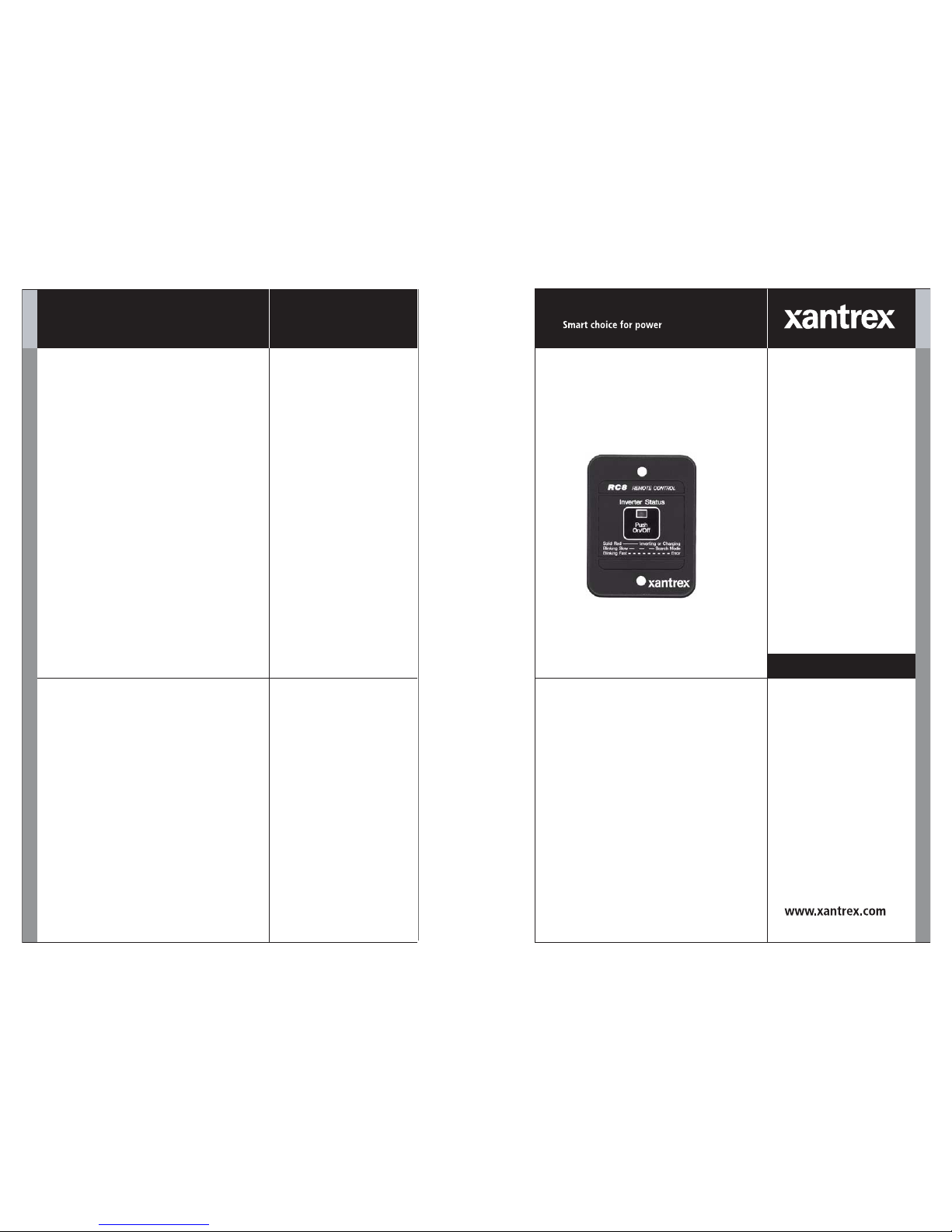
Figure 1
The RC8 Remote Control
Page 12

Introduction
2 975-0264-01-01 Rev A
Features
The RC8 Remote Control duplicates the ON/OFF power
switch on the inverter and displays general system operating
parameters.
The remote can operate the inverter from distances of up to
100 feet and connects directly to the inverter’s “RC8
Remote” or “COM” port using a special, tinned, 6-conductor
length of cable.
The RC8 Remote Control is compatible with DR Series,
Legend Series I, Voyager Series, M1512/1524 Series, Truck
Series I, TS Series, UX Series, and PS Series inverters.
The RC8 Remote Control includes the following features.
• Easy-to-Read LED
• Front Panel Control
• Plug-in Installation
• ROF - Remote Override Function (Legend Series I,
Truck Series I, and UX Series inverters only)
The following system operating parameters are displayed
with a single LED.
• Inverter Status (ON/OFF)
• Inverter/Charger Indicator
• Search Mode Indicator
• Error Indicator
Figure 2
The RC8 Remote Control Features
LED
ON/OFF Button
Operation
975-0264-01-01 Rev A 11
PS Series Inverters
When the RC8 is used with PS Series inverters, its red LED
will display the following.
• Solid
With AC line power present, the unit is charging the
batteries while directing AC to the load. With no AC line
power present, the inverter is running on the batteries and
supplying AC to the load.
• Blinking Slow (1 to 2 flashes @ 1 second intervals)
The inverter is in search mode (no load connected).
• Flickering*
The inverter has detected an overcurrent error. The LED
(and inverter) will turn OFF whenever an overcurrent
condition exceeds eight seconds.
• OFF*
The inverter is OFF or an error condition caused by
overheating, low battery voltage, or high battery voltage
has occurred.
Important:
If the LED does not come back on after pressing
the ON/OFF switch on the RC8, the error condition may not have
cleared. Check the inverter’s error indicator and consult the
operator’s manual for recommendations.
Page 13

Operation
10 975-0264-01-01 Rev A
TS Series Inverters
When the RC8 is used with TS Series inverters, its red LED
duplicates the POWER LED status display on the inverter.
• Solid
With AC line power present, the unit is charging the
batteries while directing AC to the load. With no AC line
power present, the inverter is running on the batteries and
supplying AC to the load.
• Blinking Slow (1 to 3 flashes @ 1 second intervals)
The inverter is in search mode (no load connected).
• Flickering*
The inverter has detected an overcurrent error. The LED
(and inverter) will turn OFF whenever an overcurrent
condition exceeds eight seconds.
• OFF*
The inverter is OFF or an error condition caused by
overheating, low battery voltage, or high battery voltage
has occurred.
Important:
If the LED does not come back on after pressing
the ON/OFF switch on the RC8, the error condition may not have
cleared. Check the inverter’s error indicator and consult the
operator’s manual for recommendations.
975-0264-01-01 Rev A 3
2
Installation
Chapter 2, “Installation” describes how to install the RC8
Remote Control.
Mounting the RC8 Remote Control
Mount the remote control in a clean, dry environment.
To mount the RC8 on a wall:
1. Drill a 1-7/8" diameter hole in a wall. There must be at
least 1-1/2" of clearance behind the hole. Remove any
wall insulation (if applicable) that may contact the back
of the remote.
2. Route the communications cable from the inverter up
into the opening in the wall. It is recommended that only
the 6-conductor, tinned cable (10, 25, 50 or 100 foot
length) provided with the remote be used. For optimum
performance, the distance should not exceed 100 feet.
Important:
Verify there are no electrical wires or other
hazards in the location where the unit is to be mounted.
Important:
Do not plug the cable into the inverter at this
time.
Page 14

Installation
4 975-0264-01-01 Rev A
Connecting the RC8 to the Inverter
To connect the RC8 to the inverter:
1. Connect the communications cable to the RJ11 Port on
the back of the RC8.
2. Position the remote into the opening in the wall and
secure it with the two screws provided.
3. Switch the inverter OFF. Plug the communications cable
into the “RC8 REMOTE or COM” port on the inverter.
Figure 3
Connecting the RC8 to the Inverter
+12V
RJ11 Port on the
Back of the RC8
Communications Cable
(10, 25, 50, or 100 ft.)
Mounting
holes
Connect the
Communications Cable to
the inverter at the COM Port
or RC8 Remote Port.
Note: The location of the COM port or the
RC8 Remote Port may vary depending on
the model of inverter used.
Mounting
holes
1
2
3
RJ11 Plug on
Communications
Cable
Operation
975-0264-01-01 Rev A 9
DR Series, Voyager Series and M1512/1524 Series
Inverters
When the RC8 is used with DR Series, Voyager Series, or
M1512/1524 Series inverters, its red LED will display the
following:
• Solid
With AC line power present, the unit is charging the
batteries while directing AC to the load. With no AC line
power present, the inverter is running on the batteries and
supplying AC to the load.
• Blinking Slow (1 to 3 flashes @ 1 second intervals)
The inverter is in search mode (no load connected).
• Blinking Fast (3 to 5 flashes @ 1 second intervals)
The inverter is charging the batteries.
• Flickering (3 to 5 flashes @ 1 second intervals)
The inverter has detected an overcurrent error. The LED
(and inverter) will turn OFF whenever an overcurrent
condition exceeds eight seconds.
• Erratic Blinking (0 to 3 and 2 to 5 flashes @ 2 second
intervals)
The inverter has detected an error condition caused by
overheating, low battery voltage, or high battery voltage.
•OFF
The inverter is OFF.
WARNING: Shock Hazard
On inverters equipped with a battery charger, the RC8 will not
necessarily control charging or AC pass-through. Some units will
always charge the batteries and pass AC power through to the
output whenever AC power is available. Refer to the appropriate
inverter owners manual for details. ALWAYS check the inverter’s
output to verify there is no voltage present before opening or
servicing the inverter.
Page 15

Operation
8 975-0264-01-01 Rev A
Legend Series I, Truck Series I, and UX Series
Inverters
When the RC8 is used with Legend Series I, Truck Series I,
or UX Series inverters, its red LED duplicates the LED status
display on the inverter.
• Solid
With AC line power present, the unit is charging the
batteries while directing AC to the load. With no AC line
power present, the inverter is running on the batteries and
supplying AC to the load.
• Blinking Slow (3 to 5 flashes @ 1 second intervals)
The inverter is in search mode (no load connected).
• Blinking Fast
The inverter has detected an error condition caused by
overheating, over-current, low battery voltage, or high
battery voltage. The LED (and inverter) will turn OFF
whenever an overcurrent condition exceeds eight
seconds.
• Erratic Blinking (0 to 3 and 2 to 5 flashes @ 2 second
intervals)
An error occurred while the inverter was in search mode,
usually caused by a low or high battery voltage
condition.
•OFF
The inverter is OFF.
WARNING: Shock Hazard
On inverters equipped with a battery charger, the RC8 will not
necessarily control charging or AC pass-through. Some units will
always charge the batteries and pass AC power through to the
output whenever AC power is available. Refer to the appropriate
inverter owners manual for details. ALWAYS check the inverter’s
output to verify there is no voltage present before opening or
servicing the inverter.
Remote Override Function (ROF)
975-0264-01-01 Rev A 5
Remote Override Function (ROF)
In certain installations, it may be desirable to turn a
connected 120 Vac load ON and OFF with the vehicle’s
ignition switch. For example: Many larger vehicles use a
rear-mounted 12 Vdc video camera with 120 Vac cabmounted monitor to aid in backing up. The ROF option
switches the inverter (monitor) ON at the same time the
camera is switched ON.
To prepare the RC8 for the Remote Override Function:
1. Carefully remove the RC8’s circular back cover to
expose the circuit board. The back cover can be removed
by squeezing in the latch on the white plastic standoffs on
the back of the cover.
2. Locate the pin jumper just below the RJ11 connector. It
should only be covering one pin. Lift the jumper and
reposition it over both pins. Replace the RC8’s back
cover.
3. Run a 12 volt DC wire from the vehicle’s ignition switch
(or fuse block), to the back of the RC8’s “AUX INPUT
+12 Vdc.” This wire must be protected with a properly
sized 12 volt fuse.
4. Follow the instructions on page 4 for connecting the RC8
to the inverter.
To Operate the Remote Override Function:
• Switch the vehicle’s ignition ON to start the inverter.
• Switch it OFF to stop the inverter.
CAUTION: Equipment Damage
This option is intended for use with Legend Series I, Truck
Series I, and UX Series INVERTERS only. Attempting to use
this feature with any other inverters will result in serious
damage to the inverter and remote.
Important:
When the ignition switch is OFF, the RC8 and
inverter function normally.
Page 16

Installation
6 975-0264-01-01 Rev A
Figure 4
Connecting the RC8 to the Inverter
+12V
Connect the Communications
Cable to the inverter at the
COM Port or RC8 Remote Port.
Note: The location of the COM port or
the RC8 Remote Port may vary
depending on the model of inverter
used.
RJ11 Plug on
Communications
Cable
12 Vdc Fuse
Ignition Switch
12 Vdc Wire
Jumper Pin
AUX INPUT
+12 Vdc
Communications Cable
(10, 25, 50, or 100 ft.)
RJ11 Port on the
Back of the RC8
Plastic Standoffs
Plastic Standoffs
975-0264-01-01 Rev A 7
3
Operation
Chapter 3, “Operation” describes the operation of the RC8
Remote Control.
Startup and Test
To Start up and Test the RC8 Remote Control:
1. Switch the inverter ON using the inverter’s front panel
ON/OFF switch.
2. Verify the POWER LED is ON (both inverter and
remote).
3. Press the ON/OFF switch on the RC8 to turn the inverter
OFF. Press it again to restore power.
Operation
The RC8 Remote Control operates as described in the
following sections depending on which inverter is connected
to it.
 Loading...