

Page 1
Owner’s Manual
(
)
RC5 Remote Control and Display for Models M1512 and M1524 Inverters
SET POWER TO:
STANDBY
SPS
Version 1.1
P.N. 822-3
RC5MAN11.DOC
Trace Engineering Company, Inc.
5916 195th Street N.E.
Arlington, WA 98223
Fax (360) 435 - 2229
Tel (360) 435 - 8826
Page 2

Page 3

Trace Engineering RC5 Remote Control and Display Owner’s Manual - Version 1.1 - 4/23/99
Table of Contents
Product Overview .....................................................................................1
Remote Control Operation ....................................................................... 2
Self Test
............................................................................................. 2
Using the Status Menu ............................................................................. 3
Set Power To
System Status
Battery
DC Current
AC Input
AC Output
Alarm Buzzer
....................................................................................... 3
...................................................................................... 4
................................................................................................ 5
.......................................................................................... 5
..............................................................................................5
........................................................................................... 6
....................................................................................... 6
Using the Setup Menu .............................................................................. 7
Search Sense
Auto LBCO
Bat Capacity
Battery Type
.......................................................................................7
.......................................................................................... 7
........................................................................................ 8
........................................................................................ 8
Charge Rate
Vac Dropout
Shore Pwr Amps
RC5 Setup
LCD Contrast
........................................................................................ 8
.........................................................................................8
................................................................................... 9
...........................................................................................9
....................................................................................... 9
Installation ................................................................................................. 10
Inverter Control Settings
Extending the RC5’s Cable
Troubleshooting
.................................................................................... 12
...........................................................................10
......................................................................11
RC5 Menu Map ......................................................................................... 13
Page 4

Page 5

Trace Engineering RC5 Remote Control and Display Owner’s Manual - Version 1.1 - 7/5/95 - Page 1
Product Overview
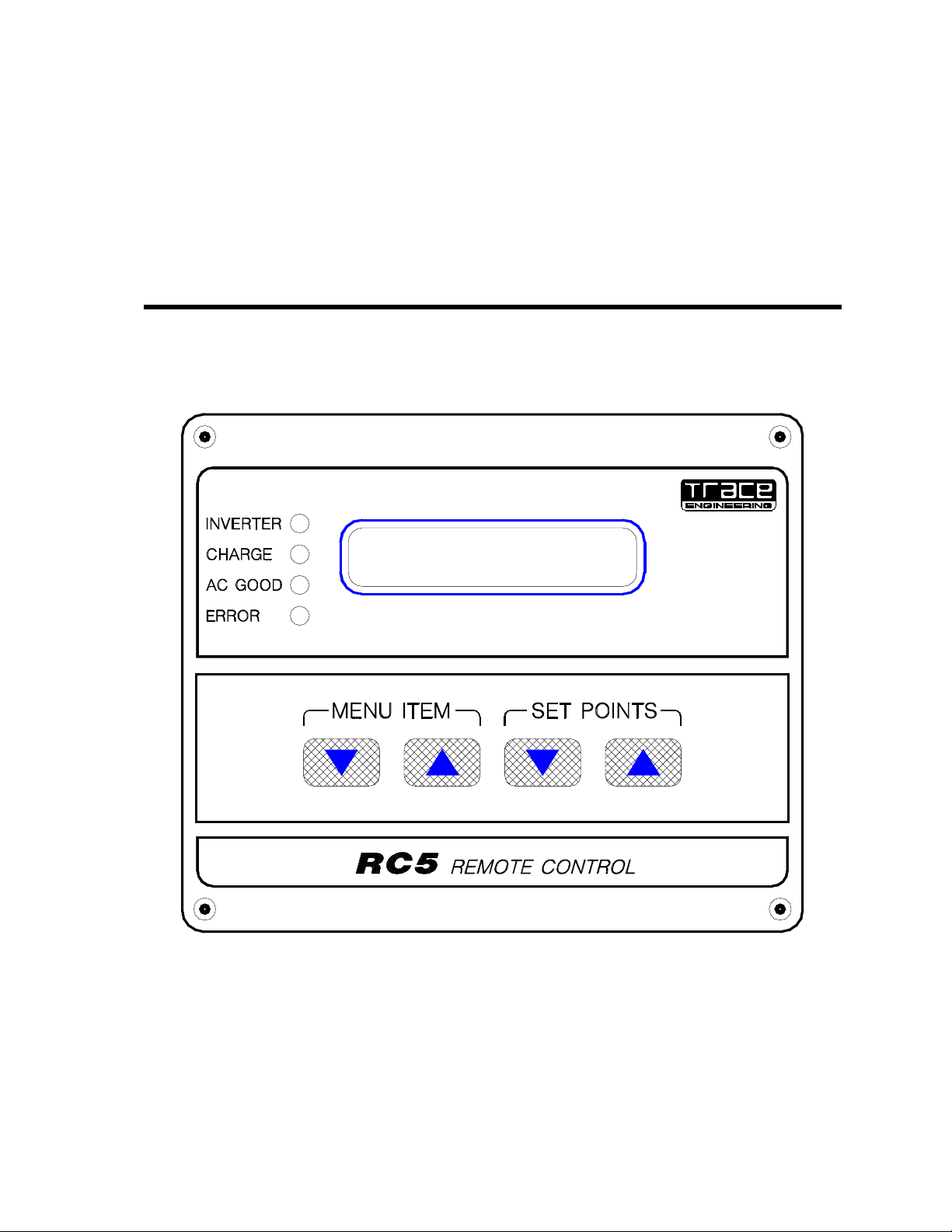
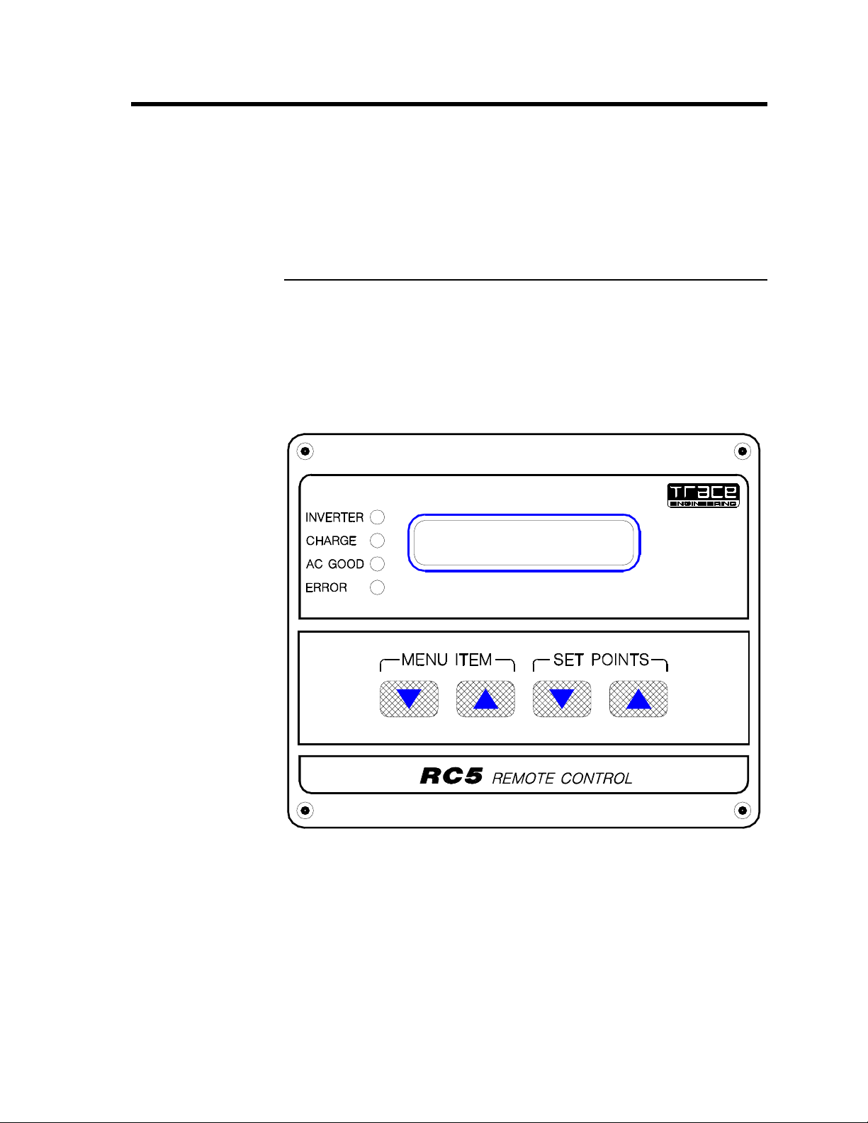
The Model RC5 is a microprocessor based remote control and display for
Trace Engineering’s Model M1512 and M1524 power inverters. Designed
for use in marine and RV applications, it provides complete remote control
and display of the inverter’s operating status and system conditions.
Features include a 32 character alphanumeric LCD display and water
resistant front panel with sealed membrane keys for use in marine
environments.
The RC5 incorporates a two level menu system, separated into a Status
Menu that provides the user with the operating information, and a Setup
Menu for use during the installation and adjustment of the system. The
remote control overrides the on/off power switch and ignores all the internal
control settings, except the “Search Watts” (see page 10).
The Status Menu provides:
•
Control of the inverter’s operating mode (off, standby and charger only).
•
Indication of the operating status (off, searching, inverting, charging, and
error condition).
•
Measurement of important system parameters (battery voltage, DC
current, and AC input and output voltages).
•
Indication of the battery’s approximate state of charge by a “gas gauge”
bar graph display.
The Setup Menu provides:
•
Adjustment of the energy saving load sensing search mode.
•
Control of the Low Battery Cut Out (LBCO) system to prevent battery
over-discharge and damage.
•
Adjustment of the battery capacity setting to improve accuracy of the
LBCO, the battery bar graph display and the charger’s return amps.
•
Selection of the battery type (gel cell or liquid lead acid).
•
Adjustment of the maximum charge rate for the battery charger.
•
Adjustment of the AC dropout voltage for the AC transfer switch.
•
Adjustment of the maximum shore power amperage available.
•
Control of the display mode (last key, power saver or rolling).
•
Adjustment of the LCD’s contrast for different lighting conditions.
The RC5 will only operate with the M1512 and M1524 inverters that include
the necessary internal software for communication. To check your inverter,
open the door and examine the labels on the integrated circuits (IC’s) on the
circuit board. The large 40 pin IC #1904-1 should be marked Rev. 120 or
higher. The small 16 pin IC #1916-1 should be marked 1.01 or higher.
Contact your Trace dealer if an upgrade of the inverter’s software is
required. The RC5 will not operate without the correct software installed.
We at Trace Engineering sincerely thank you for choosing our products and
hope that you will be completely satisfied with them.
Page 6
Trace Engineering RC5 Remote Control and Display Owner’s Manual - Version 1.1 - 7/5/95 - Page 2
(
)
Remote Control Operation
The RC5 should be connected with the inverter turned off. If the display
shows “recycle power to inverter”, turn the inverter off with the switch
located on the inverter. This is only required after the RC5 has been
disconnected from the inverter. If the display indicates this during normal
operation, check the connectors and/or replace the cable
Self Test
When the system is first powered up the display will enter the STATUS
MENU with the screen displaying a “Set Power To: Off” message. It is
normal for the RC5 to momentarily flash its multicolored LED indicators
when first turned on. This indicates that the remote display is properly
connected and ready to operate.
SET POWER TO:
STANDBY
SPS
Page 7

Trace Engineering RC5 Remote Control and Display Owner’s Manual - Version 1.1 - 7/5/95 - Page 3
Using the Status Menu
The Status Menu provides the user with the basic information and control
needed to operate the system. Use the MENU ITEM keys to move up and
down the menu. Use the SET POINTS keys to select the alternate settings.
Status Menu
Set Po wer To:___
Off
System Status:__
Inver t in g
Battery: ____
13.0 Volts
DC Current:_ __
-18 Amps
AC Input: ___
0 Vac 0 Vpk
AC Output:_ _ __
120 Vac
Use the
Use the
Values shown are typ ical du ring o perati on of the inve rter
Set Power To:
Set Power To: __
Standby (SPS )
Battery: _ ___
E F
MENU ITE M
SET POI NT S
Set Power To:___
Charger Only
keys to move up and down vertically
keys to sele ct alte rna te se ttin gs
The factory default setting is to start with the inverter turned off. To turn the
inverter on, press the down arrow SET POINTS key once to select
Standby (SPS). The inverter is now ready to operate AC loads. If operation
of only the battery charger is desired, set the display to Charger Only. This
mode is often used for systems which are left on charge and unattended for
long periods of time, such as a boat docked at a marina.
Page 8

Trace Engineering RC5 Remote Control and Display Owner’s Manual - Version 1.1 - 7/5/95 - Page 4
System Status:
To display the operating status of the system, press the down arrow MENU
ITEM key once. If you had set the inverter to the Standby (SPS) mode, it
will display either Inverting or Charging, depending upon whether AC
power is available to the battery charger’s AC input.
When AC power is available and connected to the inverter’s AC input, the
inverter will enter its battery charging mode. The first stage of the recharging
process is called Bulk Charging. In this mode the charger will provide the
full charging current to the battery. Once the battery reaches a fully charged
condition, the battery charger will switch to the next stage, called
Absorption Charging. In this mode the charger will maintain the battery at
a constant voltage level for a limited period of time to assure that the battery
is fully charged. If power is still available to the inverter, the battery charger
will next switch to Float Charging the battery to keep the battery full without
overcharging it. The inverter will remain in the Float mode until the power is
removed from the battery charger’s AC input. For more information on the
operation of the battery charger, see the owner’s manual.
If a problem occurs while the inverter is operating, the system status will
display what has occurred and what action should be taken to correct the
problem. There are four error conditions:
Hibat/Stop Chrg - The battery voltage has exceeded the operating range of
the inverter. You should turn off your charging sources to allow the voltage
level to drop. The inverter will automatically reset and begin operation when
the battery reaches a safe voltage level.
Lobat/Start Chrg - The inverter has shut off to prevent damage to the
battery. To reset the inverter, either start your generator or connect to shore
power to start charging the battery.
Otemp/Less Load - The inverter’s transformer or power components has
exceeded a safe operating temperature level. You can reduce the load on
the inverter to prevent this from occurring. When the inverter has cooled,
the inverter will automatically reset and begin operation. If this occurs often,
you should make sure the inverter is in a cool location and that it has
adequate air flow available for cooling.
Oload/Less Load - The inverter has reached its maximum design power
level and turned off. Reduce the amount of loads and restart the inverter.
Page 9

Trace Engineering RC5 Remote Control and Display Owner’s Manual - Version 1.1 - 7/5/95 - Page 5
Battery:
Information on the battery is provided by both the DC input voltage and a
“gas gauge” bar graph of the battery’s condition. To change to the bar graph
display, press the down arrow SET POINTS key once. The display will
remain in the gas gauge mode when the menu is cycled through again. To
return to the battery voltage display, press the down arrow SET POINTS key
again.
The gas gauge display compensates the battery voltage measurement for
the load and charging current flow. This provides a more accurate indication
of the battery’s condition than available from the voltage measurement
alone.
DC Current:
The DC input current is provided to indicate the inverter’s load on the battery
and the charger’s output. The DC current multiplied by the system voltage
will give an estimation’s of the load’s wattage, including the inverter’s
efficiency losses (Volts x Amps = Watts).
The value displayed will be negative while the inverter is operating,
indicating that power is flowing out of the batteries. When the battery
charger is operating, the current flow will be displayed as a positive value.
This indicates that the power is flowing into the battery.
AC Input:
The AC input voltage is provided to enable the user to check the AC power
source for battery charging. Both the average and peak voltage is
provided. The average voltage should be near 120 Vac (or 230 for “I” and
“E” export model inverters) and is a good indication of the power source’s
quality. The peak voltage should be over 160 Vac for the proper operation of
the battery charger.
Since the inverter passes through the power from the AC input to the AC
output while battery charging, the AC loads will actually be operating from
the generator or shore power.
Page 10

Trace Engineering RC5 Remote Control and Display Owner’s Manual - Version 1.1 - 7/5/95 - Page 6
AC Output:
The inverter’s output voltage regulation is indicated by the AC output voltage.
If the inverter is heavily loaded, the output voltage may drop. The display
will indicate that the inverter’s output is not within the regulation specification
by displaying <120 Vac.
When the inverter is in search mode and not operating any loads, the
display will show < 40 Vac.
Alarm Buzzer:
The RC5 includes an internal buzzer which will sound for up to five minutes
when an error condition has occurred. It will automatically reset after the
error condition is corrected.
Page 11

Trace Engineering RC5 Remote Control and Display Owner’s Manual - Version 1.1 - 7/5/95 - Page 7
Using the Setup Menu
The Setup Menu is accessed by holding down the two MENU ITEM keys at
the same time for approximately five seconds. To return to the Status
Menu, hold both of the MENU ITEM keys for approximately one second.
To get more information on any of the following control settings, see the
inverter’s owner manual. It includes detailed explanations of each control
and examples of appropriate settings for different applications.
The RC5 will override all of the inverter’s internal control settings, except for
the search watts. If the RC5 is disconnected, the inverter will use the
internal control settings after a one minute delay. If the inverter is
disconnected from the battery, or if the communication cable is
disconnected, the RC5’s settings will return to the factory default values.
You may want to note the settings chosen for your system on the “menu
map” included in the back of this manual.
Search Sense:
This setting controls the sensitivity of the inverter’s load sensing circuitry.
The circuit board mounted control inside the inverter must be set at 50
watts (or at 12 o’clock) for proper operation of the RC5 to occur. You
should check the search sense setting when you connect the RC5, before
you operate the system.
The factory default setting for the RC5 is to defeat the search mode. This
means that the inverter will not reduce its power consumption when there
are no loads connected. To adjust the setting, use the SET POINTS keys
to change the value shown.
Auto LBCO:
The low battery cut out (LBCO) circuit provides over-discharge protection to
the battery. It monitors both the battery voltage and the current being drawn
by the inverter to more accurately estimate the battery’s condition.
If the Auto LBCO control is set to off, the inverter will continue to operate
until the battery is fully discharged. This may cause damage to the battery.
The inverter will then shut off to protect itself. It will automatically be reset if
AC power is provided to the battery charger’s AC input.
You can de-activate the Auto LBCO control by pressing the down arrow
SET POINTS key once. It can be re-activated by pressing the SET POINTS
key again.
Page 12

Trace Engineering RC5 Remote Control and Display Owner’s Manual - Version 1.1 - 7/5/95 - Page 8
Bat Capacity:
The LBCO “load compensation” circuit, the “gas gauge” display and the
battery charger’s return amp setting require information on the battery bank
size to accurately operate. The battery bank size is adjustable from 50 to
1000 amp-hours. Use the SET POINTS keys to select the closest setting to
the size of your battery. Be sure that the battery’s rating you are using is not
the batteries “cold cranking amps” rating. for more information, see the
inverter’s owner manual section on batteries.
Battery Type:
The battery charger’s settings are optimized for two types of batteries. The
default battery type is Gel Cell. To select Liquid Lead Acid, press the
down arrow SET POINTS key once.
Charge Rate:
You can adjust the battery charger’s maximum output current level by
adjusting the Charge Rate %. The M1512 has a maximum charge rate of
70 amps and the M1524 is 35 amps. Use the SET POINTS keys to adjust
the charger’s output to fine tune the battery charger’s operation.
Vac Dropout:
The inverter constantly monitors the AC input’s voltage level. If it drops to a
low level, the inverter will disconnect the AC input, turn off the battery
charger and power the loads from the battery. The voltage level is
adjustable from 80 Vac to 105 Vac (160 Vac to 210 Vac for export models).
Use the SET POINTS keys to select the best setting for your application. A
lower setting will reduce transfers due to voltage fluctuations, but may result
in a slightly longer transfer time when the shore power fails or is
disconnected.
Page 13

Trace Engineering RC5 Remote Control and Display Owner’s Manual - Version 1.1 - 7/5/95 - Page 9
Shore Pwr Amps:
The shore power amperage setting is adjustable. The inverter monitors the
AC power being drawn by both the battery charger and the AC loads
connected to the inverter. If the level approaches the circuit breaker’s rating,
the battery charger will “back off” to prevent tripping and loss of power. For
this to operate properly, all of the AC loads should be connected to the
inverter’s output. Any loads which operate off of shore power directly will not
be included, which may result in nuisance tripping of the shore power circuit
breaker. Use the SET POINTS keys to adjust the setting for your
application.
This control can also be used to prevent overloading of backup generators if
they are used to charge the battery, as well. Adjust the setting to match the
generator’s maximum continuous output. This is usually lower than the
rating of the circuit breaker provided on the generator’s output.
RC5 Setup:
The RC5 has three display modes for the Status Menu to suit the
preferences of the system user:
Last Key - This is the default setting for the RC5. The display will remain
with the same menu item as when you last left it.
Power Saver - In this mode, both the LCD display and the LED’s will turn
off after five minutes to reduce power consumption. When any key is
pressed, the display will turn on with the same display as before (the first
key stroke is ignored). If an error condition occurs, the display will be turned
on until the problem is corrected.
Rolling Display - In this mode the display will begin to cycle through the
Status Menu after no keys have been pressed for five minutes. Each display
is shown for approximately three seconds. After a key is pressed, the
display will be stationary for five minutes, and then resume the rolling
display.
Use the SET POINTS keys to select the desired display mode.
LCD Contrast:
The display’s contrast is adjustable to improve readability in different lighting
conditions. Use the SET POINTS keys to set the contrast to the best level.
Page 14

Trace Engineering RC5 Remote Control and Display Owner’s Manual - Version 1.1 - 7/5/95 - Page 10
Installation
The RC5 is easy to install. The following is the recommended installation
procedure:
1. Select a location for the RC5 to be mounted.
2. Use the provided template to mark the cut-out required.
3. Install the cable from the inverter to the RC5’s location.
4. Protect the cable from physical damage by sharp edges, etc.
5. Route the cable away from potential sources of interference such as
high powered antennas.
6. Connect the phone type cable to the RC5 before installing into cut-out.
7. Install the RC5 into the cut-out opening and seal with foam rubber or
silicone sealant if required.
8. Turn off the inverter by the switch on the front of the cabinet.
9. Disconnect the inverter from the battery.
10. Open the cabinet’s door to access the main circuit board.
11. Plug the cable into the jack labeled “J4” on the door mounted circuit
board at the bottom. It is the left most jack of the 3 jacks provided.
12. Check the Search Watt setting - it must be set at 50 watts (at the 12
o’clock position). All other control settings are ignored when the RC5 is
connected to the inverter.
13. Reconnect the battery and turn on the inverter.
The RC5 is now operational and ready to use. If you are installing the RC5
in an area which may be exposed to direct spray or rain, you should seal the
back of the front panel to the mounting surface with either a soft foam rubber
gasket or silicone sealant.
Inverter Control Settings
The RC5 overrides all of the inverter’s internal control settings except the
search watts control. This must be set at 50 watts to allow the RC5 to
adjust the search mode circuitry remotely. This setting is straight up
or at the 12 o’clock position. The other control settings are all ignored
while the RC5 is connected. If the RC5 is disconnected, the inverter returns
to the control of the internal settings.
Note: the default setting for the search mode when the RC5 is connected is
to disable its operation. You must set the search sense to the appropriate
wattage level for it to operate. If the inverter is disconnected from the battery
or the RC5 is unplugged, you must reset the search sense setting and any
other settings you require. You can record the settings used on the menu
map provided at the end of this manual for future reference.
Page 15

Trace Engineering RC5 Remote Control and Display Owner’s Manual - Version 1.1 - 7/5/95 - Page 11
Extending the RC5’s Cable
The RC5 includes a 50 foot cable for connection to the inverter. The cable is
a specially made for Trace Engineering using stranded and tinned 26 gauge
wires. This should be long enough for most applications. If you require
additional cable length, the cable can be extended up to 150 feet with
standard phone cable and a female-to-female connector. Do not use a
second RC5 cable for the extension. Do not cut the cable if it is too long.
Bundle and tie off the additional cable at a convenient location.
If you want to make a your own custom length cable, it must be made up to
match the cable provided. The RC5 requires that the cable’s phone jack
connectors be flipped in orientation from each other. This only applies
when you are not using the cable provided, not when you are simply
extending the cable by adding a phone cable and a female-to-female
connector. Examine the cable provided and duplicate it exactly.
You must protect the cable from damage by sharp edges and abrasion.
SEARCH WATTS (R1)
must be set at the
12 o’clock position for
the RC5 to work right.
All other controls are
ignored by the RC5.
J1 is used only for the
RC4 remote on/off
switch. Both can be
used together.
Connect the cable from
the RC5 to the jack
labeled “J4”
M15JACKS.WMF
J2 is only used for
temperature
compensation sensor
Page 16

Trace Engineering RC5 Remote Control and Display Owner’s Manual - Version 1.1 - 7/5/95 - Page 12
Trouble Shooting
The display reads “Recycle Power to Inverter”.
If the inverter is operating, simply push the power switch on the front panel
of the inverter. The communication link will be re-established between the
inverter and the RC5. If the inverter ignores the RC5’s control settings,
simply push any key on the front panel of the RC5. The communication link
will be re-established between the RC5 and the inverter. The RC5 has
evidently become disconnected while operating the inverter.
Repeated problems with the RC5’s communication link with the inverter is a
sign of a either a poor connection or damaged cable. Check the cable for
breaks or cuts and reconnect. Replace the cable if the problem continues.
The display is blank.
Check the cable to the RC5 from the inverter. Make sure that the
connectors are fully inserted and in the correct jack (J4). Examine the cable
for damage such as cuts or breaks. Try replacing the cable with another
RC5 cable (a standard phone cable will not work).
The settings have changed back to the default values.
Either the inverter has been disconnected from the battery or the RC5 has
been disconnected from the inverter. You must reselect your settings on the
RC5.
Be sure that the inverter is not disconnected from the battery when you
select different battery banks by selecting the “BOTH” position and not the
“OFF” when changing.
You can also set the internal controls to your preferred settings to allow the
system to operate properly if the RC5 is disconnected or is not operational.
The inverter defaults to its internal controls.
I extended the cable and the RC5 does not work now.
You must use the provided cable together with any extension cables
required. A female to female connector will be required to connect the
cables together. You can also cut the provided cable and slice in additional
wire if you carefully match the wires back together.
Page 17

Trace Engineering RC5 Remote Control and Display Owner’s Manual - Version 1.1 - 7/5/95 - Page 13
 Loading...