

Xantrex PROSINE 1000i, PROSINE 1000, PROSINE 1800, PROSINE 1800i Owner's Manual

1000
1000i
1800
1800i
Owner’s Manual
Xantrex Prosine
Sine Wave Inverter
1000/1800


English
Xantrex Prosine Inverter Owner’s Manual
Table of Contents
Important Safety Instructions .......................................................................................................................................................................................... 1
1. Introduction ................................................................................................................................................................................................................ 3
1.1 Prosine Inverter Key Features .......................................................................................................................................................................... 3
2. Installation.................................................................................................................................................................................................................. 4
2.1 Requirements for Installation ............................................................................................................................................................................ 4
2.2 Locating the Prosine Inverter ............................................................................................................................................................................ 4
2.3 Mounting the Prosine Inverter........................................................................................................................................................................... 4
2.4 Wiring the Prosine Inverter ............................................................................................................................................................................... 5
2.4.1 Input and Output Protection ..............................................................................................................................................................................................5
2.4.2 Making AC Wiring Connections ........................................................................................................................................................................................6
2.4.3 Ground Fault Circuit Interrupters (GFCIs) ........................................................................................................................................................................7
2.4.4 Making DC Wiring Connections ........................................................................................................................................................................................7
3. Prosine Inverter Operation ......................................................................................................................................................................................... 9
3.1 Principles of Operation ...................................................................................................................................................................................... 9
3.2 Output Waveform ............................................................................................................................................................................................. 9
3.3 Control Panel ...................................................................................................................................................................................................10
3.4 Prosine POWERSAVE Mode...........................................................................................................................................................................10
3.5 Inverter Operating Limits and Protection Features ..........................................................................................................................................11
4. Testing........................................................................................................................................................................................................................11
5. Troubleshooting Guide..............................................................................................................................................................................................12
5.1 Fault Conditions and Indicators........................................................................................................................................................................12
6. Warranty ...................................................................................................................................................................................................................13
7. Appendices................................................................................................................................................................................................................14
7.1 Battery Type......................................................................................................................................................................................................14
7.2 Battery Size......................................................................................................................................................................................................15
8. Performance Graphs.................................................................................................................................................................................................16
8.1 Power Derating Curve.......................................................................................................................................................................................16
8.2 Efficiency Curve...............................................................................................................................................................................................17
9. Specifications............................................................................................................................................................................................................18

English
SUPERIOR, PACER are registered trademarks of TROJAN BATTER Y Company
SEA VOL T , SEAGEL are registered trademarks of WEST MARINE PRODUCTS
VOYAGER is a registered trademark of DELCO-REMY
GENESIS is a registered trademark of GATES ENERGY PRODUCTS (HA WKER ENERGY)
EVOLYTE is a registered trademark of GNB INDUSTRIAL BA TTER Y CO.
PREV AILER is a registered trademark of SONNENSCHEIN
Xantrex Prosine Inverter Owner’s Manual
Trademarks
Xantrex, Prosine, and Smart Choice For Power are trademarks of Schneider Electric Services International sprl, registered
in the U.S. and other countries.
Other trademarks, registered trademarks, and product names are the property of their respective owners and are used
herein for identification purposes only.
Notice of Copyright
Xantrex Prosine Sine Wave Inverter 1000, 1000i/1800, 1800i Owner’s Manual © January 2009, 2005-2008 Xantrex
Technology Inc. All rights reserved. No part of this document may be reproduced in any form or disclosed to third parties
without the express written consent of: Xantrex Technology Inc., 161-G South Vasco Road, Livermore, California USA
94551.
Xantrex Technology Inc. reserves the right to revise this document and to periodically make changes to the content hereof
without obligation or organization of such revisions or changes unless required to do so by prior arrangement.
Exclusion for Documentation
UNLESS SPECIFICALLY AGREED TO IN WRITING, XANTREX TECHNOLOGY INC., (“XANTREX TECHNOLOGY”)
(A) MAKES NO WARRANTY AS T O THE ACCURACY, SUFFICIENCY OR SUIT ABILITY OF ANY TECHNICAL OR OTHER INFORMATION PROVIDED
IN ITS MANUALS OR OTHER DOCUMENTATION.
(B) ASSUMES NO RESPONSIBILITY OR LIABILITY FOR LOSSES, DAMAGES, COSTS OR EXPENSES, WHETHER SPECIAL, DIRECT, INDIRECT,
CONSEQUENTIAL OR INCIDENTAL, WHICH MIGHT ARISE OUT OF THE USE OF SUCH INFORMATION. THE USE OF ANY SUCH
INFORMATION WILL BE ENTIRELY AT THE USER’S RISK; AND
(C) REMINDS YOU THAT IF THIS MANUAL IS IN ANY LANGUAGE OTHER THAN ENGLISH, ALTHOUGH STEPS HA VE BEEN TAKEN T O MAINTAIN
THE ACCURACY OF THE TRANSLATION, THE ACCURACY CANNOT BE GUARANTEED. APPROVED CONTENT IS CONTAINED WITH THE
ENGLISH LANGUAGE VERSION WHICH IS POSTED AT WWW.XANTREX.COM.
Date and Revision
January 2009, Revision B
Part Number
445-0049-01-01
Contact Information
Web: www.xantrex.com
Email: customerservice@xantrex.com
Phone: 1-800-670-0707 (in North America), 1-408-987-6030 (direct)
Fax: 1-800-994-7828 (in North America), 1-604-422-2756 (direct)
English 1
Important Safety Instructions
General Safety Precautions
1. SA VE THESE INSTRUCTIONS. This OWNER’S
MANUAL contains important safety and operating
information for the Prosine Inverter.
2. Do not expose the Prosine Inverter to rain, snow,
spray, bilge or dust. To reduce risk of fire hazard,
do not cover or obstruct the ventilation openings.
Do not install the Prosine Inverter in a zeroclearance compartment. Overheating may result.
3. Do not use attachments not recommended or sold
by Xantrex. Doing so may result in a risk of fire,
electric shock, or injury to persons.
4. The Prosine Inverter is designed to be permanently
connected to your DC electrical systems (and for
hardwire versions, permanently connected to your
AC electrical system). To ensure adherence to
proper electrical wiring regulations all wiring must
be done by a certified technician or electrician.
5. To avoid a risk of fire and electric shock, make
sure that existing wiring is in good electrical
condition; and that wire size is not undersized. Do
not operate the Prosine Inverter with damaged or
substandard wiring.
6. Do not operate the Prosine Inverter if it has received
a sharp blow, been dropped, or otherwise damaged
in any way. If the Prosine Inverter has been
damaged, refer to Section 6 of this manual.
7. Do not disassemble the Prosine Inverter; refer to
Section 6 of this manual for instructions on
obtaining service for the Prosine Inverter.
Attempting to service the unit yourself may result
in a risk of electrical shock or fire.
8. To reduce risk of electrical shock, disconnect the
DC power (and AC power if applicable on hardwire
versions) from the Prosine Inverter before
attempting any maintenance or cleaning or working
on any equipment and circuits connected to the
Prosine Inverter. T urning off controls will not reduce
this risk.
9. Grounding: The Prosine Inverter must be provided
with an equipment-grounding conductor connected
to the AC input ground terminal. Grounding and
all other wiring must comply with local codes and
ordinances.
10. For marine applications, special installation codes
may apply. For example, in the U.S., the installation
shall comply with the United States Coast Guard
Electrical Regulations (33CFR183, Sub part 1).
Explosive Gas Precautions
1. This equipment contains components which can
produce arcs or sparks. To prevent fire or explosion
do not install in compartments containing batteries
or flammable materials or in locations which require
ignition protected equipment.This includes any
space containing gasoline-powered machinery, fuel
tanks, or joints, fittings, or other connection between
components of the fuel system.
2. Working in the vicinity of a lead-acid battery is
dangerous. Batteries generate explosive gases
during normal battery operation.
3. To reduce the risk of battery explosion, follow these
instructions and those published by the battery
manufacturer and the manufacturer of the
equipment in which the battery is installed.
Precautions When Working With
Batteries
1. Someone should be within range of your voice or
close enough to come to your aid when you work
near a lead-acid battery.
2. Have plenty of fresh water and soap nearby in case
battery acid contacts skin, clothing, or eyes.
3. Wear complete eye protection and clothing
protection. A void touching eyes while working near
batteries.
4. Clean battery terminals before making connections.
Wear eye protection to keep corrosion from coming
in contact with eyes.
5. If battery acid contacts skin or clothing, wash
immediately with soap and water. If acid enters eye,
immediately flood eye with running cold water for
at least 20 minutes and get medical attention
immediately.
6. NEVER smoke or allow a spark or flame in vicinity
of battery or engine.
7. Do not drop a metal tool on the battery. The resulting
spark or short-circuit on the battery or other
electrical part may cause an explosion.
8. Remove personal metal items such as rings,
bracelets, necklaces, and watches when working
with a lead-acid battery. A lead-acid battery
produces a short-circuit current high enough to weld
a ring or the like to metal, causing a severe burn.
WARNING
Before you install and use your Prosine
Inverter, be sure to read and save these safety
instructions.
Xantrex Prosine Inverter Owner’s Manual

2 English
Xantrex Prosine Inverter Owner’s Manual
English 3
1. Introduction
Thank you for your purchase of this Prosine Sine
Wave Inverter. As a high quality, true sine wave output
inverter, you can expect exceptional performance and
years of dependable operation. The true sine wave AC
output from the inverter ensures all AC loads operating
from the unit perform efficiently and correctly. Since
these loads were designed to operate from true sine wave
voltage, you can expect these loads to operate the same
as if operating from grid/utility supplied power. In some
cases, the true sine wave output from the Xantrex inverter
is even superior to the power supplied by your utility
company.
To get the most out of your Prosine Inverter, carefully
read and follow the instructions in this guide. Pay special
attention to the Important Safety Instructions and to the
CAUTION and WARNING statements found
throughout the manual and on the product. Please retain
all packaging.
Should you have any questions before, during, or after
installation, please contact Xantrex.
Phone: 1-800-670-0707, 1-408-987-6030 (direct)
Fax: 1-800-994-7828, 1-604-422-2756 (direct)
Email: customerservice@xantrex.com
We b: www.xantrex.com
1.1 Prosine Inverter Key Features
The Prosine Inverter utilizes advanced high frequency
switching technology in the power conversion process.
The circuits are similar to those used in power supplies
for computers and other electronic equipment. This
technology offers several benefits:
• Light weight: for easy installation
• Totally silent: for quiet operation
• High surge capability: for “hard-to-start” AC loads
See Section 10 (Specifications) for complete product
specifications.
1.1.1 Inverter Function
When connected properly and the power switch is turned
to the (I) position, the inverter draws power from a battery
and delivers a true sine wave AC output voltage. If the
battery voltage is within the operating range of the unit,
the inverter will continue to deliver AC power to the
loads connected. High and low battery shutdowns will
engage if the battery voltage falls out of the specified
range of operation (10–16 VDC on 12 V models, 20–32
VDC on 24 V models).
1.1.2 Control Panel
The Control Panel displays operating information so you
can monitor the status of the Inverter and your batteries.
This panel can be removed and re-attached in different
orientations so the information is directed at you in the
most convenient fashion, for all recommended mounting
configurations. With the optional Interface Panel, the
display can be fully removed from the base chassis and
remotely located in the place of your choice (e.g. on the
dash of your vehicle).
1.1.3 Automatic Transfer Switch
Your Prosi ne Inverter may be equipped with a transfer
relay if specified prior to purchase. The transfer relay serves
two purposes: 1) allows the AC output of the inverter to
be wired into an existing AC system as a source of power
and 2) allows the Prosine Inverter to automatically
become the source of power should your utility source
fail.
When utility AC power fails, the transfer relay is deenergized and the load is automatically transferred to the
inverter output within 20–30 milliseconds. With the
POWERSAVE feature enabled (recommended for
reducing standby power consumption), AC output from
the inverter may be delayed for up to 2½ seconds. Once
AC utility is restored, the relay energizes and the load is
automatically reconnected to AC utility.
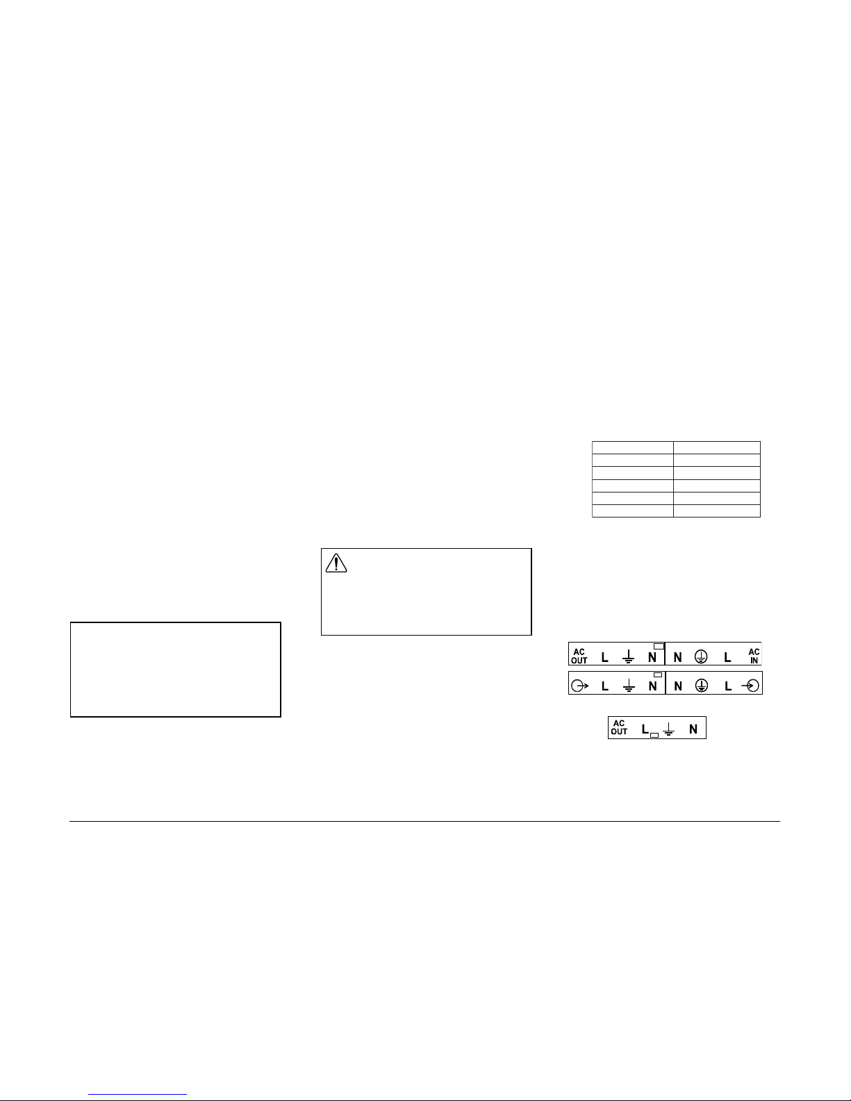
Identifying Models With Transfer Switches
1) Check the UPC code on the product box. Units with
transfer switches have UPC codes that end with these five
digits:
2) If there is an AC outlet on the front of the unit, it is
not equipped with an internal transfer switch.
3) For Prosine Inverters with hardwire connections, you
can identify whether your unit has an internal transfer
switch by removing the cover on the AC wiring
compartment and checking the label above the terminal
block inside.
If your unit has a label similar to one of these two
labels, it has an internal transfer switch:
Units with this label do not have an internal transfer
switch:
i0001/0001ledoMi0081/0081ledoM
4801648816
4701647816
2501625816
8001680816
2001620816
WARNING
Note that in (
##
##
#) (Bypass) position the front panel
switch does NOT turn off all voltages inside the
unit. This control only deactivates the AC
conversion circuitry. On AC hardwire/transfer relay versions any utility voltage present on the AC
input terminals will be present on the AC output
terminals.
Please record the following information if you need
to contact Xantrex for servicing of the unit.
Serial No.: ___________________________
Place of purchase: ___________________________
Date of purchase: ___________________________
Xantrex Prosine Inverter Owner’s Manual

4 English
Xantrex Prosine Inverter Owner’s Manual
2. Installation
This section contains instructions for installing the
Xantrex Prosine Inverter. After securing the unit and
making wiring connections, do not turn the unit on.
Proceed to the next section of the manual which provides
operating instructions.
2.1 Requirements for Installation
Installation Regulations: Depending on the type of
location in which you are installing the Prosine Inverter,
there are different codes and regulations that the
installation must meet such as your national and local
electrical codes for residential installations. Other examples
of codes and regulations for North American installations
include:
• US Coast Guard and ABYC requirements for
installations on marine vessels
• RV Industry Association (RVIA), CSA, and UL
requirements for installations in recreational vehicles.
It is the installer´s responsibility to ensure that all
applicable installation requirements are met.
What You Need to Install the Prosine Inverter
You need the following tools and hardware to properly
install the inverter:
• wire stripper
• mounting screws/bolts (¼” or 6mm diameter screws)
• small flat blade screwdriver (for hardwire versions)
• small Phillips screwdriver
• wrench for DC terminals (½” or 13mm)
• AC wiring for hardwire configured models (see AC
wiring section for details)
• DC cables (see DC wiring section for details)
• Wire connectors and crimp tool for your DC cables
• AC and DC disconnects and over-current protective
devices (see section 2.4.1 for details)
2.2 Locating the Prosine Inverter
The inverter utilizes complex electronic circuits, and
although design precautions have been made for protection
of these circuits, they can be susceptible to damage from
use in extreme environments. The Prosine Inverter should
only be installed in a location that meets the following
requirements:
• Dry:do not allow water or other fluids to drip or splash
on the Prosine Inverter. Do not mount the inverter in an
area subject to splashing or dripping water or bilge.
• Cool: normal ambient air temperature should be between
0°C (32°F) and 25°C (77°F)—the cooler the better within
this range. Refer to the operating temperature information
in section 9 (specifications) for more details.
• V entilated: allow at least 5 inches (13 cm) of clearance
all around the unit. Ensure the ventilation openings on the
unit are not obstructed. If mounting in a compartment,
ventilate with louvers or cut-outs.
• Safe: do not install the Prosine Inverter in the same
compartment as batteries or in any compartment capable
of storing flammable liquids such as gasoline. Do not
install the inverter in an engine compartment or other
location where ignition protected equipment is required.
• Dust-free: do not install the Prosine Inverter in a dusty
environment where either dust, wood particles or other
filings/shavings are present. These can be pulled into the
unit when the cooling fan is operating.
• Close to AC junction box: avoid the use of extended
wire lengths if possible.
• Close to battery/batteries: Avoid excessive cable
lengths but do not install the Prosine Inverter in the same
compartment as batteries. Use the recommended wire
lengths and sizes (see section 2.4.4). Also do not mount
the inverter where it will be exposed to the gases
produced by the battery. These gases are very corrosive
and prolonged exposure will damage the inverter.
• Protected from battery acid: never allow battery acid
to drip on the Prosine Inverter or its wiring when reading
specific gravity or filling the battery.
2.3 Mounting the Prosine Inverter
Before mounting the Prosine Inverter, test the chosen
location for adequate space around the unit to allow for
connections and ventilation. Mounting hardware should
be corrosion resistant and ¼” or 6mm diameter screws.
Your mounting system should be able to support three
times the weight of the inverter, which weighs
approximately 16 lbs (7.3Kg). The more clearance for
ventilation around the unit, the better the performance.
At a minimum, have 5” of free space on all sides of the
inverter.
To mount the Prosine Inverter
1. Mount the Prosine Inverter on either a horizontal or
vertical surface (such as a bulkhead) using the
mounting holes provided. For secure, permanent
mounting, use all eight mounting holes. To meet
regulatory requirements, the inverter must be
mounted in one of the three orientations shown.
CAUTION
The Pro sine Inverter is designed to be
permanently connected to your DC electrical
system. When Configured as an AC hardwire
version, the inverter is also designed to be
permanently connected to your AC electrical
system. T o ensure adherence to proper electrical
wiring regulations, all wiring must be done by a
certified technician or electrician.
WARNING
Review the Important Safety Instructions found
at the beginning of this manual and read this
entire section, paying particular attention to the
CAUTION and WARNING statements, before
proceeding with the installation.
Figure 1. Approved orientations for
inverter mounting
 Loading...