

Page 1
MS2000 Sine Wave Inverter/Charger
Operation Guide
MS2000
Page 2

Page 3

MS2000 Sine Wave Inverter/Charger
Operation Guide
Page 4

About Xantrex
Xantrex Technology Inc. is a world-leading supplier of advanced power electronics and controls with products from
50 watt mobile units to one MW utility -s cale systems for wind, solar, batteries, fuel cel ls, microturbines, and backup
power applications in both grid-connec ted and stand-alone syst em s . Xantrex products include inverters, battery
chargers, programmable power supplies, and variable speed drives that convert, supply, control, clean, and distribute
electri cal pow er.
T rademarks
MS2000 Sine Wave Inverte r/Charger is a trad emark of Xantrex International. Xantrex and Xanbus are regis tered
trademarks of Xantrex International.
Other trademarks, registered trademarks, and product names ar e the property of their respective owners and are used
herein for identi fication purposes onl y.
Notice of Copyright
MS2000 Sine Wave Inv erter/Charger Operation Guide © August 2004 Xant rex International. All rights reserved.
Disclaimer
UNLESS SPECIFICALLY AGREED TO IN WRITING, XANTREX TECHNOLOGY INC. (“XANTREX”)
(a) MAKES NO WARRANTY AS TO THE ACCURACY, SUFFICIENCY OR SUITABILITY OF ANY
TECHNICAL OR OTHER INFORMAT ION PROVIDED IN ITS MANUALS OR OTHER DOCUMENTATION.
(b) ASSUMES NO RESPONSIBILITY OR LIABILITY FOR LOSS OR DAMAGE, WHETHER DIRECT,
INDIRECT, CONSEQUENTIAL OR INCIDENTAL, WHICH MIGHT ARISE OUT OF THE USE OF SUCH
INFORMATION. THE USE OF ANY SUCH INFORMATION WILL BE ENTIREL Y AT THE USER’S RISK.
Date and Revision
August 2004 Rev A
Part Number
975-0125-02-01
Contact Information
Telephone: 1 800 670 0707 (toll free North America )
1 360 925 5097 (direct)
Fax: 1 800 994 7828 (toll free North America)
1 360 925 5143 (direct)
Email: customerservice@xantrex.com
Web: www.xantrex.com
Page 5

975-0125-02-01 iii
About This Guide
Purpose
The MS2000 Sine Wave Inverter/Charger Operation Guide provides explanations
and procedures for operating, configuring, and troubleshooting the MS2000 Sine
Wave Inverter/Charger (MS2000).
Scope
The guide provides safety guide line s and information about operatin g,
configuring, and troubleshooting the unit. It does not include installation
information or battery information. Refer to the MS2000 Sine Wave Inverter/
Charger Installation Guide.
For detailed information about particular brands of batteries, you will need to
consult individua l battery manufacturers.
Audience
The guide is intended for users who need to operate, configure, and troubleshoot
the MS2000 Sine Wave Inverter/Charger.
Organization
This guide is organized into four chapters and three appendixes.
Chapter 1, “Introduction”, outlines the main p erfo rm an c e an d safe ty fea tures of
the MS2000 Sine Wave Inverter/Charger. Reading this chapter will give you a
clear understanding of the inverter/charger’s capabilities.
Chapter 2, “Operation”, provides information about operating the MS2000.
Details are provided on how to read the front panel indicators to monitor the
MS2000.
Chapter 3, “Configuration”, explains how to configure the MS2000 from the
control panel.
Chapter 4, “Troubleshooting”, explains how to identify and solve problems that
can occur with the MS2000.
Appendix A, “Specifications” provides electr ical, physical, and performance
specifications f or the inverter/charger. It also provides Echo Charger
specifications.
Appendix B, “Battery Charging Refere n ce for the Main Charger ” provides
information on three-stage charging, two-stage charging, and charging times.
Appendix C, “Terminology” provides a glossary and a listing of commonly used
abbrevations and acro nyms.
Page 6
About This Guide
iv 975-0125-02-01
“W arranty and Product Infor mation” contains the product warranty, explains how
to return a product for service, and describes what to prepare for a call to Xantrex
Customer Se rvice.
Conv en t io n s Used
The following conventions are used in this guide.
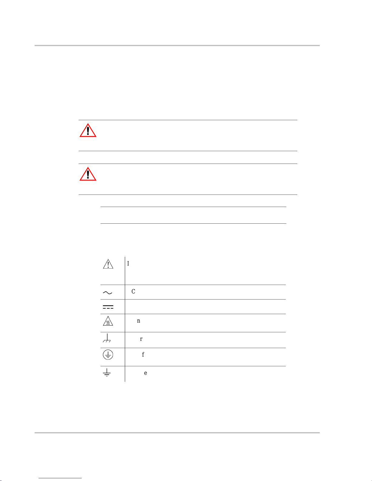
Symbols Used
The following symbols are used on the product labels or in this guide.
WARNING
Warnings iden tify conditions or prac tices that could resu lt in personal injury or
loss of life.
CAUTION
Cautions i dentif y co ndit ion s or pra ctic es th at cou ld r esult in damage t o t he unit or
other equipment.
Important:
These notes describe an important action item or an item that
you must pay attention to.
&
In this guide: Important information, warnings or cautions.
On the product: Important information, warnings or cautions
with further expla nation in the product guides.
AC – Alternating current
(
DC – Direct current
%
Warning: Hot su rf ace. Do not touch.
DC ground connection point
AC safety ground connection point from incoming AC source
AC safety ground connection point for AC output (to AC loads)
Page 7

About This Guide
975-0125-02-01 v
Relat ed Inf o rmation
For related materials on this product and its available accessor ies, see also:
MS2000 Sine Wave Inverter/Charger Installation Guide (975-0126-02-01)
System Control Panel Owner’s Guide (975-0083-01-01)
Automatic Generator Start Owner’s Guide (975-0082-01-01)
Xanbus System Installation Guide (975-0136-01-01)
More information about Xantr ex Technology Inc. as well as its products and
services, including a complete list of Xanbus-enabled devices, is available at
www.xantrex.com
Contact Inform ation
Telephone: 1 800 670 0707 (toll free North America)
1 360 925 5097 (direct)
Fax: 1 800 994 7828 (toll free North America)
1 360 925 5143 (direct)
Email: customerservice@xantrex.com
Web: www.xantrex.com
Page 8

vi
Page 9
975-0125-02-01 vii
Important Safety Instructions
READ AND SAVE THESE INSTRUCTIONS
The MS2000 Sine Wave Inverter/Charger Operation Guide contains important
safety instructions.
Before you install and use your MS2000 Sine Wa ve Inverter/Charger, be sure to
read, understand and save these safety instructions and those in the othe r product
guides.
Read all instructions and cautionary markings on the inverter/charger, the
batteries and all appr opriate sections of this guide.
1. Use of accessories not recommended or sold by Xantrex Technology, Inc.
may result in a risk of fire, electric shock, or injury to persons.
2. The inverter/charger is designed to be permanen tly connected to your AC and
DC electrical systems. Xantrex recommends that a ll wiring be done by a
certified technician or electrician to ensure adherence to the local and national
electrical code s applicable in your application.
3. To a void a risk of fir e and electric shock, make sure that the existing wiring is
in good condition and that the wire is not undersized. Do not operate the
inverter/charger with damaged or substandard wiring.
4. To reduce ri sk of damage and injury, charge only recharge able
lead-acid batter ies: flooded, gel, or absorbed glass mat (AGM) types. Other
types of batteries may burst causing personal injury and damage.
5. Do not operate the inverter/charger if it has received a sharp blow, been
dropped, or otherwise damaged in any way. If the unit is damaged, see the
“W arranty and Product Informat ion” section in the MS2000 Sine Wave
Inverter/Charger Operation Guide.
6. Do not disassemble the inverter/charger; it does not contain user servic eable
parts. Take it to a qualified service person when service or repair is requi red.
Incorrect reassembly may result in a risk of electrical shock or fire. Internal
WARNING: Risk of injury or loss of life
The MS2000 Sine Wave Inverter/Charger shall not be used in connection with
life support systems or other medical equipment or devices.
WARNING
The following warnings identify conditions or practices that could result in
personal injury or loss of life.
Page 10
Safety
viii 975-0125-02-01
capacitors rem ain charged after all power is disconne cted. For instructions on
obtaining service, see the “Warranty and Product Information” section in the
MS2000 Sine Wave Inverter/Charger Operation Guide.
7. Do not expose the inverter/charger to rain, snow , or splashing bilge water.
8. To reduce ri sk of electric shock, disconnect all sour ces of AC and DC power
from the inverter/charger attempting any maintenance or cleaning. Turning
off controls will not r educe this risk.
9. The inverter/charger must be provided with equipment grounding conductors
connected to the AC input ground and chassis ground terminals.
To reduce the risk of overheating, keep the ventilation openings clear and do not
install the invert er/charger in a compartment with limited airflow or inadequate
clearances around the unit. Refer to the MS2000 Sine Wave Inverter/Charge r
Installation Guide for required clearance.
CAUTION
Cautions i dentif y co ndit ion s or pra ctic es th at cou ld r esult in damage t o t he unit or
other equipment.
Page 11
Safety
975-0125-02-01 ix
Explosiv e Gas Precaut ions
1. To reduce ri sk of battery explosion, follow these instructions and those
published by the batt ery manufa ctur er and the manuf acturer of any equipment
you intend to use in the vicinity of a batte ry. Review cautionary markings on
these products and on the engine.
2. This equipment contains components which tend to produce arcs or spark. To
prevent fire or explosion, do not install the inverter/charger in compartments
containing batteries or flammable materials or in locations that require
ignition-prot ected equipment. This includes any space conta ining gasolinepower machinery, fuel tanks, as well as joints, fittings, or other connections
between components of the fuel system.
Personal Precautions When Working With Batteries
1. Someone should be within range of your voice or close enough to come to
your aid when you work near a lead-acid battery.
2. Have plenty of fresh water and soap nearby in case battery acid cont acts your
skin, clothing, or eyes.
3. Wear complete eye protection and clothing protection. Avoid touching your
eyes while wo rki ng near batteries.
4. If battery acid conta cts you r skin or cl othing, wa sh immedi atel y with soa p and
water. If acid enters your eye, immediately flood the eye with running cold
water for at least ten minutes and get medical attention immediately.
5. Never smoke or allow a spark or flame in the vicinity of the battery or engine .
6. Be extra cautious to reduce risk of dropping a metal tool onto a batter y. It
might spark or short-cir cuit battery or other electrical parts that may cause
explosion.
7. Remove personal metal items such as rings, bracele ts, necklaces, and watches
when working with a lead-acid battery. A lead-acid battery can produce a
short-circuit c urrent high enough to we ld a ring or the like to metal, causing a
severe burn.
8. Never charge a frozen battery.
WARNING: Risk of explosive gases
Working in the vicinity of a lead-acid battery is dangerous. Batteries generate
explosive gases during normal battery operat ion. For this reason, it is of utm os t
importance that you must read this guide and follow its instructions closely each
time befor e you service equipment in the vicinity of the batt er y.
Page 12

Safety
x 975-0125-02-01
9. If it is necessary to remove a battery, always remove the grounded terminal
from the battery first. Make sure all accessories are off, so as not to cause an
arc.
10. Be sure area around battery is well ventilated.
11. Clean the battery terminals. Be careful to keep corrosion from coming in
contact with your eyes.
12. Study all battery manufacturer’s specific precauti ons such as removing or not
removing cell caps while charging and the recommended rates of charge.
13. For refillable (flooded) batteries, add distilled water in each cell until the
battery acid reac hes the lev el spec ifie d by the b attery manufactu rer. This helps
to purge excessive gas from cells. Do not overfill. Carefully follow the
manufacturer’s recharging instruc tions.
FCC Information to the User
This equipment has been teste d and found to comply with the limits fo r a Class B
digital device, pursuant to part 15 of the FCC Rules. These limits are designed to
provide reasona ble protection a gainst harmful int erference when the equipment is
operated in a residential environment. This equipment generates, uses and can
radiate radio freque nc y energy and, if not installed and used in accorda nce with
the instruction guide , may cause harmful interference to radio communications.
However, there is no guarantee that interference will not occur in a particular
installati on. I f this equipment does cause harmful interference to radio or
television reception, which can be determined by turning the equipment off and
on, the user is encouraged to try to corre ct the interference by one or more of the
following measures:
• Reorient or relocate the rece iving antenna.
• Increase the separation between the equipment and the receiver.
• Connect the equipment into an outlet on a circuit different from that to which
the receiver is connected.
• Consult the dealer or an experie nced r adio/TV technician for help.
Page 13

975-0125-02-01 xi
Important Safety In str uctions
- - - - - - - - - - - - - - - - - - - - - - - - - - - - - - - - - - - - - - - - - - -vii
1
Introduction
About the MS2000 Sine Wave Inverter/Charge r- - - - - - - - - - - - - - - - - - - - - - - - - - - - - - - - - - 1–2
Premium Power and Ease of Use - - - - - - - - - - - - - - - - - - - - - - - - - - - - - - - - - - - - - - - - - 1–2
How MS2000 Works - - - - - - - - - - - - - - - - - - - - - - - - - - - - - - - - - - - - - - - - - - - - - - - - - 1–3
Inverting - - - - - - - - - - - - - - - - - - - - - - - - - - - - - - - - - - - - - - - - - - - - - - - - - - - - - - - 1–3
Charging - - - - - - - - - - - - - - - - - - - - - - - - - - - - - - - - - - - - - - - - - - - - - - - - - - - - - - - 1–3
Xanbus System - - - - - - - - - - - - - - - - - - - - - - - - - - - - - - - - - - - - - - - - - - - - - - - - - - - - - 1–5
Xanbus Enabled - - - - - - - - - - - - - - - - - - - - - - - - - - - - - - - - - - - - - - - - - - - - - - - - - - - - - 1–5
Comprehensive Electronic Protection - - - - - - - - - - - - - - - - - - - - - - - - - - - - - - - - - - - - - - - - - 1–6
MS2000 Features - - - - - - - - - - - - - - - - - - - - - - - - - - - - - - - - - - - - - - - - - - - - - - - - - - - - - - 1–7
Front Panel Features - - - - - - - - - - - - - - - - - - - - - - - - - - - - - - - - - - - - - - - - - - - - - - - - - - 1–7
Side Panel Features - - - - - - - - - - - - - - - - - - - - - - - - - - - - - - - - - - - - - - - - - - - - - - - - - - 1–9
DC Terminal Covers and Battery Temperature Sensor - - - - - - - - - - - - - - - - - - - - - - - - - - 1–11
DC Terminal Covers - - - - - - - - - - - - - - - - - - - - - - - - - - - - - - - - - - - - - - - - - - - - - - 1–11
Battery Temperature Sensor - - - - - - - - - - - - - - - - - - - - - - - - - - - - - - - - - - - - - - - - - 1–11
System Accessories and Network Compone nts- - - - - - - - - - - - - - - - - - - - - - - - - - - - - - - - - - 1–12
2
Operation
Operating the MS2000 with the System Control Panel- - - - - - - - - - - - - - - - - - - - - - - - - - - - - - 2–2
Using the System Control Panel- - - - - - - - - - - - - - - - - - - - - - - - - - - - - - - - - - - - - - - - - - - - - 2–3
On Start Up - - - - - - - - - - - - - - - - - - - - - - - - - - - - - - - - - - - - - - - - - - - - - - - - - - - - - - - - - - 2–4
Power On Reset - - - - - - - - - - - - - - - - - - - - - - - - - - - - - - - - - - - - - - - - - - - - - - - - - - - - - - - 2–4
System Start-up Check - - - - - - - - - - - - - - - - - - - - - - - - - - - - - - - - - - - - - - - - - - - - - - - - - - - 2–5
System Modes - - - - - - - - - - - - - - - - - - - - - - - - - - - - - - - - - - - - - - - - - - - - - - - - - - - - - - - - 2–6
Operate Mode - - - - - - - - - - - - - - - - - - - - - - - - - - - - - - - - - - - - - - - - - - - - - - - - - - - - - - 2–7
Power Save Mode - - - - - - - - - - - - - - - - - - - - - - - - - - - - - - - - - - - - - - - - - - - - - - - - - - - 2–7
Safe Mode - - - - - - - - - - - - - - - - - - - - - - - - - - - - - - - - - - - - - - - - - - - - - - - - - - - - - - - - 2–8
Putting the System into Safe Mode - - - - - - - - - - - - - - - - - - - - - - - - - - - - - - - - - - - - - 2–9
Hibernate mode - - - - - - - - - - - - - - - - - - - - - - - - - - - - - - - - - - - - - - - - - - - - - - - - - - - - 2–10
Operating in Invert Mode - - - - - - - - - - - - - - - - - - - - - - - - - - - - - - - - - - - - - - - - - - - - - - - - 2–12
Load Sense Mode - - - - - - - - - - - - - - - - - - - - - - - - - - - - - - - - - - - - - - - - - - - - - - - - - - - 2–12
Operating Limits for Inverter Operation - - - - - - - - - - - - - - - - - - - - - - - - - - - - - - - - - - - - 2–13
Power Output - - - - - - - - - - - - - - - - - - - - - - - - - - - - - - - - - - - - - - - - - - - - - - - - - - - 2–13
Operating in Charger Mode- - - - - - - - - - - - - - - - - - - - - - - - - - - - - - - - - - - - - - - - - - - - - - - 2–14
Echo Charger Operation - - - - - - - - - - - - - - - - - - - - - - - - - - - - - - - - - - - - - - - - - - - - - - 2–15
Enabling and Disabling Operation from the System Control Panel - - - - - - - - - - - - - - - 2–15
Contents
Page 14

Contents
xii 975-0125-02-01
Charger Operation with Battery Temperature Sensor - - - - - - - - - - - - - - - - - - - - - - - - - - -2–17
Operating in Equalization Mode - - - - - - - - - - - - - - - - - - - - - - - - - - - - - - - - - - - - - - - - - - - -2–18
Equalizing Batteries - - - - - - - - - - - - - - - - - - - - - - - - - - - - - - - - - - - - - - - - - - - - - - - - -2–19
Terminating the Equalization Process - - - - - - - - - - - - - - - - - - - - - - - - - - - - - - - - - - - - - -2–22
Operating Limits for Charger Operation - - - - - - - - - - - - - - - - - - - - - - - - - - - - - - - - - - - -2–22
Power Share - - - - - - - - - - - - - - - - - - - - - - - - - - - - - - - - - - - - - - - - - - - - - - - - - - - - - - -2–22
Monitoring the MS2000 Indicat or Lights - - - - - - - - - - - - - - - - - - - - - - - - - - - - - - - - - - - - - -2–23
Faults and Warnings - - - - - - - - - - - - - - - - - - - - - - - - - - - - - - - - - - - - - - - - - - - - - - - - - - - -2–24
Monitoring Status Messages on the System Control Panel- - - - - - - - - - - - - - - - - - - - - - - - - - -2–24
3
Configuration
General Configuration Information - - - - - - - - - - - - - - - - - - - - - - - - - - - - - - - - - - - - - - - - - - 3–2
System Control - - - - - - - - - - - - - - - - - - - - - - - - - - - - - - - - - - - - - - - - - - - - - - - - - - - - - 3–2
System Menu Map - - - - - - - - - - - - - - - - - - - - - - - - - - - - - - - - - - - - - - - - - - - - - - - - - - - - - 3–3
Viewing the System Screen - - - - - - - - - - - - - - - - - - - - - - - - - - - - - - - - - - - - - - - - - - - - 3–4
Viewing the Select Device Menu - - - - - - - - - - - - - - - - - - - - - - - - - - - - - - - - - - - - - - - - - 3–4
Selecting the MS2000 Basic Menu - - - - - - - - - - - - - - - - - - - - - - - - - - - - - - - - - - - - - - - - 3–5
Selecting and Adjusting the Configurable settings - - - - - - - - - - - - - - - - - - - - - - - - - - - - - 3–5
MS2000 Configuration Menus - - - - - - - - - - - - - - - - - - - - - - - - - - - - - - - - - - - - - - - - - - - - - 3–6
MS2000 Device Menu- - - - - - - - - - - - - - - - - - - - - - - - - - - - - - - - - - - - - - - - - - - - - - - - - - - 3–8
Mode - - - - - - - - - - - - - - - - - - - - - - - - - - - - - - - - - - - - - - - - - - - - - - - - - - - - - - - - - - - 3–8
Battery - - - - - - - - - - - - - - - - - - - - - - - - - - - - - - - - - - - - - - - - - - - - - - - - - - - - - - - - - - 3–9
AC Input - - - - - - - - - - - - - - - - - - - - - - - - - - - - - - - - - - - - - - - - - - - - - - - - - - - - - - - - - 3–9
AC Out - - - - - - - - - - - - - - - - - - - - - - - - - - - - - - - - - - - - - - - - - - - - - - - - - - - - - - - - - - 3–9
Echo Chg Out - - - - - - - - - - - - - - - - - - - - - - - - - - - - - - - - - - - - - - - - - - - - - - - - - - - - - - 3–9
MS2000 Menu (Basic) - - - - - - - - - - - - - - - - - - - - - - - - - - - - - - - - - - - - - - - - - - - - - - - - - -3–10
Inverter - - - - - - - - - - - - - - - - - - - - - - - - - - - - - - - - - - - - - - - - - - - - - - - - - - - - - - - - - -3–10
Charger - - - - - - - - - - - - - - - - - - - - - - - - - - - - - - - - - - - - - - - - - - - - - - - - - - - - - - - - - -3–11
Power Share - - - - - - - - - - - - - - - - - - - - - - - - - - - - - - - - - - - - - - - - - - - - - - - - - - - - - - -3–12
Equalize - - - - - - - - - - - - - - - - - - - - - - - - - - - - - - - - - - - - - - - - - - - - - - - - - - - - - - - - -3–12
Batt Type - - - - - - - - - - - - - - - - - - - - - - - - - - - - - - - - - - - - - - - - - - - - - - - - - - - - - - - - -3–15
Batt Size - - - - - - - - - - - - - - - - - - - - - - - - - - - - - - - - - - - - - - - - - - - - - - - - - - - - - - - - -3–15
Clear Faults - - - - - - - - - - - - - - - - - - - - - - - - - - - - - - - - - - - - - - - - - - - - - - - - - - - - - - -3–16
MS2000 Menu (Advanced) - - - - - - - - - - - - - - - - - - - - - - - - - - - - - - - - - - - - - - - - - - - - - - -3–17
Inverter - - - - - - - - - - - - - - - - - - - - - - - - - - - - - - - - - - - - - - - - - - - - - - - - - - - - - - - - - -3–17
Charger - - - - - - - - - - - - - - - - - - - - - - - - - - - - - - - - - - - - - - - - - - - - - - - - - - - - - - - - - -3–17
Power Share - - - - - - - - - - - - - - - - - - - - - - - - - - - - - - - - - - - - - - - - - - - - - - - - - - - - - - -3–17
Configure Inv/Chg (Configure Inverter/Charger) - - - - - - - - - - - - - - - - - - - - - - - - - - - - - -3–17
Max Chg Rate - - - - - - - - - - - - - - - - - - - - - - - - - - - - - - - - - - - - - - - - - - - - - - - - - - - - -3–18
Echo Chg - - - - - - - - - - - - - - - - - - - - - - - - - - - - - - - - - - - - - - - - - - - - - - - - - - - - - - - - -3–18
Load Sense - - - - - - - - - - - - - - - - - - - - - - - - - - - - - - - - - - - - - - - - - - - - - - - - - - - - - - - -3–19
Equalize - - - - - - - - - - - - - - - - - - - - - - - - - - - - - - - - - - - - - - - - - - - - - - - - - - - - - - - - -3–19
Page 15

Contents
975-0125-02-01 xiii
Clear Faults - - - - - - - - - - - - - - - - - - - - - - - - - - - - - - - - - - - - - - - - - - - - - - - - - - - - - - - 3–19
View Device Info - - - - - - - - - - - - - - - - - - - - - - - - - - - - - - - - - - - - - - - - - - - - - - - - - - - 3–19
Basic Menu - - - - - - - - - - - - - - - - - - - - - - - - - - - - - - - - - - - - - - - - - - - - - - - - - - - - - - - 3–19
Selecting the MS2000 Advanced Menu - - - - - - - - - - - - - - - - - - - - - - - - - - - - - - - - - - - - 3–20
Returning to MS2000 Basic Menu - - - - - - - - - - - - - - - - - - - - - - - - - - - - - - - - - - - - - - - 3–21
Sub-Menus- - - - - - - - - - - - - - - - - - - - - - - - - - - - - - - - - - - - - - - - - - - - - - - - - - - - - - - - - - 3–22
Configure Inv/Chg Menu (Configure Inverter/Charger Menu) - - - - - - - - - - - - - - - - - - - - - 3–22
Lo DC Volt - - - - - - - - - - - - - - - - - - - - - - - - - - - - - - - - - - - - - - - - - - - - - - - - - - - - 3–22
Batt Type - - - - - - - - - - - - - - - - - - - - - - - - - - - - - - - - - - - - - - - - - - - - - - - - - - - - - 3–22
Batt Size - - - - - - - - - - - - - - - - - - - - - - - - - - - - - - - - - - - - - - - - - - - - - - - - - - - - - - 3–22
Sense Below - - - - - - - - - - - - - - - - - - - - - - - - - - - - - - - - - - - - - - - - - - - - - - - - - - - 3–22
Sense Interval - - - - - - - - - - - - - - - - - - - - - - - - - - - - - - - - - - - - - - - - - - - - - - - - - - 3–23
Cfg AC Lim its (Co nfi g ure A C L imi t s) - - - - - - - - - - - - - - - - - - - - - - - - - - - - - - - - - - 3–23
# Chg Stages - - - - - - - - - - - - - - - - - - - - - - - - - - - - - - - - - - - - - - - - - - - - - - - - - - - 3–23
Eqz Volts - - - - - - - - - - - - - - - - - - - - - - - - - - - - - - - - - - - - - - - - - - - - - - - - - - - - - 3–24
Force Charge - - - - - - - - - - - - - - - - - - - - - - - - - - - - - - - - - - - - - - - - - - - - - - - - - - - 3–24
Cfg AC Limits (Configure AC Limits) - - - - - - - - - - - - - - - - - - - - - - - - - - - - - - - - - - - - 3–25
Lo AC Volt - - - - - - - - - - - - - - - - - - - - - - - - - - - - - - - - - - - - - - - - - - - - - - - - - - - - 3–25
Lo AC Freq - - - - - - - - - - - - - - - - - - - - - - - - - - - - - - - - - - - - - - - - - - - - - - - - - - - - 3–25
Hi AC Volt - - - - - - - - - - - - - - - - - - - - - - - - - - - - - - - - - - - - - - - - - - - - - - - - - - - - 3–26
Hi AC Freq - - - - - - - - - - - - - - - - - - - - - - - - - - - - - - - - - - - - - - - - - - - - - - - - - - - - 3–26
View Device Info Menu (Device Information Menu) - - - - - - - - - - - - - - - - - - - - - - - - - - - 3–27
View Fault Log - - - - - - - - - - - - - - - - - - - - - - - - - - - - - - - - - - - - - - - - - - - - - - - - - 3–27
View Warning Log - - - - - - - - - - - - - - - - - - - - - - - - - - - - - - - - - - - - - - - - - - - - - - - 3–27
View Event Log - - - - - - - - - - - - - - - - - - - - - - - - - - - - - - - - - - - - - - - - - - - - - - - - - 3–27
Restore Defaults - - - - - - - - - - - - - - - - - - - - - - - - - - - - - - - - - - - - - - - - - - - - - - - - - 3–28
4
Troubleshooting
Faults and Warnings - - - - - - - - - - - - - - - - - - - - - - - - - - - - - - - - - - - - - - - - - - - - - - - - - - - - 4–2
Fault Types - - - - - - - - - - - - - - - - - - - - - - - - - - - - - - - - - - - - - - - - - - - - - - - - - - - - - - - - 4–2
Warning Types - - - - - - - - - - - - - - - - - - - - - - - - - - - - - - - - - - - - - - - - - - - - - - - - - - - - - 4–3
Troubleshooting Reference - - - - - - - - - - - - - - - - - - - - - - - - - - - - - - - - - - - - - - - - - - - - - - - - 4–4
General Troubleshoot ing Guidelines- - - - - - - - - - - - - - - - - - - - - - - - - - - - - - - - - - - - - - - - - - 4–5
Warning Messages- - - - - - - - - - - - - - - - - - - - - - - - - - - - - - - - - - - - - - - - - - - - - - - - - - - - - - 4–6
Fault Messages - - - - - - - - - - - - - - - - - - - - - - - - - - - - - - - - - - - - - - - - - - - - - - - - - - - - - - - - 4–9
Inverter Applications - - - - - - - - - - - - - - - - - - - - - - - - - - - - - - - - - - - - - - - - - - - - - - - - - - - 4–15
Resistive Loads - - - - - - - - - - - - - - - - - - - - - - - - - - - - - - - - - - - - - - - - - - - - - - - - - - - - 4–15
Motor Loads - - - - - - - - - - - - - - - - - - - - - - - - - - - - - - - - - - - - - - - - - - - - - - - - - - - - - - 4–15
Problem Loads - - - - - - - - - - - - - - - - - - - - - - - - - - - - - - - - - - - - - - - - - - - - - - - - - - - - - 4–15
Very Small Loads - - - - - - - - - - - - - - - - - - - - - - - - - - - - - - - - - - - - - - - - - - - - - - - - 4–15
Fluorescent Lights & Power Supplies - - - - - - - - - - - - - - - - - - - - - - - - - - - - - - - - - - 4–15
Clocks - - - - - - - - - - - - - - - - - - - - - - - - - - - - - - - - - - - - - - - - - - - - - - - - - - - - - - - 4–16
Searching - - - - - - - - - - - - - - - - - - - - - - - - - - - - - - - - - - - - - - - - - - - - - - - - - - - - - 4–16
Page 16

Contents
xiv 975-0125-02-01
A
Specifications
Inverter Specifications- - - - - - - - - - - - - - - - - - - - - - - - - - - - - - - - - - - - - - - - - - - - - - - - - - - A–2
Main Charger Specifications - - - - - - - - - - - - - - - - - - - - - - - - - - - - - - - - - - - - - - - - - - - - - - A–3
Echo Charger Specifications- - - - - - - - - - - - - - - - - - - - - - - - - - - - - - - - - - - - - - - - - - - - - - - A–4
Transfer and General Specifications - - - - - - - - - - - - - - - - - - - - - - - - - - - - - - - - - - - - - - - - - A–4
Environmental Specifications - - - - - - - - - - - - - - - - - - - - - - - - - - - - - - - - - - - - - - - - - - - - - - A–5
Physical Specifications with Projections- - - - - - - - - - - - - - - - - - - - - - - - - - - - - - - - - - - - - - - A–5
Regulatory Approvals - - - - - - - - - - - - - - - - - - - - - - - - - - - - - - - - - - - - - - - - - - - - - - - - - - - A–5
Fan Operation - - - - - - - - - - - - - - - - - - - - - - - - - - - - - - - - - - - - - - - - - - - - - - - - - - - - - - - - A–5
Invert Power Derating vs Ambient Temperature - - - - - - - - - - - - - - - - - - - - - - - - - - - - - - - - - A–6
Charger Mode - - - - - - - - - - - - - - - - - - - - - - - - - - - - - - - - - - - - - - - - - - - - - - - - - - - - - - - - A–6
B
Battery Charging Reference for the Main Charger
Charging Algorithms (Formulas) - - - - - - - - - - - - - - - - - - - - - - - - - - - - - - - - - - - - - - - - - - - B–2
Battery Type - - - - - - - - - - - - - - - - - - - - - - - - - - - - - - - - - - - - - - - - - - - - - - - - - - - - - - B–2
Charge Algorithm Stages- - - - - - - - - - - - - - - - - - - - - - - - - - - - - - - - - - - - - - - - - - - - - - - - - B–2
Three-stage charging - - - - - - - - - - - - - - - - - - - - - - - - - - - - - - - - - - - - - - - - - - - - - - - - - B–2
Bulk Charge - - - - - - - - - - - - - - - - - - - - - - - - - - - - - - - - - - - - - - - - - - - - - - - - - - - - B–3
Absorption Charge - - - - - - - - - - - - - - - - - - - - - - - - - - - - - - - - - - - - - - - - - - - - - - - - B–3
Float Charge - - - - - - - - - - - - - - - - - - - - - - - - - - - - - - - - - - - - - - - - - - - - - - - - - - - - B–3
Equalization Charge - - - - - - - - - - - - - - - - - - - - - - - - - - - - - - - - - - - - - - - - - - - - - - - B–4
Two-Stage Charging - - - - - - - - - - - - - - - - - - - - - - - - - - - - - - - - - - - - - - - - - - - - - - - - - B–4
Charge Algorithm Graph - - - - - - - - - - - - - - - - - - - - - - - - - - - - - - - - - - - - - - - - - - - - - - - - - B–5
Charge Algorithm Definitions - - - - - - - - - - - - - - - - - - - - - - - - - - - - - - - - - - - - - - - - - - - - - B–5
AC Reconnect Summary - - - - - - - - - - - - - - - - - - - - - - - - - - - - - - - - - - - - - - - - - - - - - - - - - B–6
C
Terminology
Glossary - - - - - - - - - - - - - - - - - - - - - - - - - - - - - - - - - - - - - - - - - - - - - - - - - - - - - - - - - - - - C–2
Abbreviations - - - - - - - - - - - - - - - - - - - - - - - - - - - - - - - - - - - - - - - - - - - - - - - - - - - - - - - - C–5
Warranty and Product Information
- - - - - - - - - - - - - - - - - - - - - - - - - - - - - - - - - - WA–1
Warranty- - - - - - - - - - - - - - - - - - - - - - - - - - - - - - - - - - - - - - - - - - - - - - - - - - - - - - - - - - WA–1
Return Procedure - - - - - - - - - - - - - - - - - - - - - - - - - - - - - - - - - - - - - - - - - - - - - - - - - - - - WA–3
Out of Warranty Service - - - - - - - - - - - - - - - - - - - - - - - - - - - - - - - - - - - - - - - - - - - - - - - WA–3
Information About Your System- - - - - - - - - - - - - - - - - - - - - - - - - - - - - - - - - - - - - - - - - - WA–4
Index
- - - - - - - - - - - - - - - - - - - - - - - - - - - - - - - - - - - - - - - - - - - - - - - - - - - - - - - - - - - - - - - IX–1
Page 17

975-0125-02-01 xv
Figure 1-1 Typical Xanbus System Diagram - - - - - - - - - - - - - - - - - - - - - - - - - - - - - - - - - - - - - 1–5
Figure 1-2 Front Panel of the MS2000- - - - - - - - - - - - - - - - - - - - - - - - - - - - - - - - - - - - - - - - - - 1–7
Figure 1-3 Front Panel Lights and Buttons - - - - - - - - - - - - - - - - - - - - - - - - - - - - - - - - - - - - - - - 1–8
Figure 1-4 Completed Connections on Side Panel - - - - - - - - - - - - - - - - - - - - - - - - - - - - - - - - - - 1–9
Figure 1-5 DC Grounding Completed - - - - - - - - - - - - - - - - - - - - - - - - - - - - - - - - - - - - - - - - - 1–10
Figure 1-6 Battery Terminal Covers - - - - - - - - - - - - - - - - - - - - - - - - - - - - - - - - - - - - - - - - - - 1–11
Figure 1-7 Battery Temperature Sensor - - - - - - - - - - - - - - - - - - - - - - - - - - - - - - - - - - - - - - - - 1–11
Figure 2-1 System Control Panel - - - - - - - - - - - - - - - - - - - - - - - - - - - - - - - - - - - - - - - - - - - - - 2–3
Figure 2-2 System Control Panel - - - - - - - - - - - - - - - - - - - - - - - - - - - - - - - - - - - - - - - - - - - - - 2–6
Figure 2-3 Operate Mode - - - - - - - - - - - - - - - - - - - - - - - - - - - - - - - - - - - - - - - - - - - - - - - - - - 2–7
Figure 2-4 Power Save Mode- - - - - - - - - - - - - - - - - - - - - - - - - - - - - - - - - - - - - - - - - - - - - - - - 2–8
Figure 2-5 Select Device Menu - - - - - - - - - - - - - - - - - - - - - - - - - - - - - - - - - - - - - - - - - - - - - - 2–9
Figure 2-6 System Settings Menu - - - - - - - - - - - - - - - - - - - - - - - - - - - - - - - - - - - - - - - - - - - - - 2–9
Figure 2-7 Safe Mode- - - - - - - - - - - - - - - - - - - - - - - - - - - - - - - - - - - - - - - - - - - - - - - - - - - - 2–10
Figure 2-8 Select Device Menu - - - - - - - - - - - - - - - - - - - - - - - - - - - - - - - - - - - - - - - - - - - - - 2–15
Figure 2-9 Echo Charger- - - - - - - - - - - - - - - - - - - - - - - - - - - - - - - - - - - - - - - - - - - - - - - - - - 2–16
Figure 2-10 Echo Charger Enabled- - - - - - - - - - - - - - - - - - - - - - - - - - - - - - - - - - - - - - - - - - - - 2–16
Figure 2-11 Battery Temperature Sensor - - - - - - - - - - - - - - - - - - - - - - - - - - - - - - - - - - - - - - - - 2–17
Figure 2-12 Equalize On- - - - - - - - - - - - - - - - - - - - - - - - - - - - - - - - - - - - - - - - - - - - - - - - - - - 2–19
Figure 2-13 Equalize Confirmation Warning - - - - - - - - - - - - - - - - - - - - - - - - - - - - - - - - - - - - - 2–20
Figure 2-14 Equalization Home Screen - - - - - - - - - - - - - - - - - - - - - - - - - - - - - - - - - - - - - - - - - 2–20
Figure 2-15 Equalize Cancellation Warning- - - - - - - - - - - - - - - - - - - - - - - - - - - - - - - - - - - - - - 2–21
Figure 3-1 System Menu Map - - - - - - - - - - - - - - - - - - - - - - - - - - - - - - - - - - - - - - - - - - - - - - - 3–3
Figure 3-2 MS2000 Float System Screen ( Example) - - - - - - - - - - - - - - - - - - - - - - - - - - - - - - - - 3–4
Figure 3-3 Select Device Menu - - - - - - - - - - - - - - - - - - - - - - - - - - - - - - - - - - - - - - - - - - - - - - 3–4
Figure 3-4 MS2000 Basic Menu in Invert Mode - - - - - - - - - - - - - - - - - - - - - - - - - - - - - - - - - - - 3–5
Figure 3-5 MS2000 Menu - - - - - - - - - - - - - - - - - - - - - - - - - - - - - - - - - - - - - - - - - - - - - - - - - - 3–6
Figure 3-6 MS2000 Menu Structure — Overview - - - - - - - - - - - - - - - - - - - - - - - - - - - - - - - - - - 3–7
Figure 3-7 Invert Mode - Basic Menu - - - - - - - - - - - - - - - - - - - - - - - - - - - - - - - - - - - - - - - - - - 3–8
Figure 3-8 Equalize On- - - - - - - - - - - - - - - - - - - - - - - - - - - - - - - - - - - - - - - - - - - - - - - - - - - 3–13
Figure 3-9 Equalize Confirmation Warning - - - - - - - - - - - - - - - - - - - - - - - - - - - - - - - - - - - - - 3–13
Figure 3-10 Equalization System Home Screen - - - - - - - - - - - - - - - - - - - - - - - - - - - - - - - - - - - 3–13
Figure 3-11 Equalize Cancellation Warning- - - - - - - - - - - - - - - - - - - - - - - - - - - - - - - - - - - - - - 3–14
Figure 3-12 Highlighting System on the Select Device Menu - - - - - - - - - - - - - - - - - - - - - - - - - - 3–20
Figure 3-13 Highlighting Global Menus - - - - - - - - - - - - - - - - - - - - - - - - - - - - - - - - - - - - - - - - 3–20
Figure 3-14 Restore Defaults Warning - - - - - - - - - - - - - - - - - - - - - - - - - - - - - - - - - - - - - - - - - 3–28
Figure A-1 Inverter Output Power vs Ambient Temperature - - - - - - - - - - - - - - - - - - - - - - - - - - - A–6
Figure B-1 Three-Stage Charging Profile - - - - - - - - - - - - - - - - - - - - - - - - - - - - - - - - - - - - - - - - B–5
Figures
Page 18

xvi
Page 19

1
Introduction
Congratulations on your purchase of the MS2000 Sine Wave Inverter/
Charger.
The MS2000 has been designed to give you premium power, ease of
use, and outstanding reliability .
Please read this chapter to familiarize yourself with the main
performance and protection features of the MS2000.
Page 20

Introduction
1–2 975-0125-02-01
About the MS2000 Sine Wave Inverter/Charger
The MS2000 Sine Wave Inverter/Charger is a convenient combination of an
inverter, multistage battery charger, transfer switch, and Echo Char ger in one
electronic d evi ce.
• As an inverter, the MS2000 provides sine wave power for your microwave,
entertainment system, computer, and other loads. This power is identical to
the AC source provided from the utility gr id (power company).
Some of the benefits of sine wave power include consistent cooking in your
microwave, handling of sensitiv e loads such as your TV set, dimmer switches,
and appliances with speed cont ro ls.
• As a 100 amp charger , the MS2000 quickly and completely recharges your
batteries.
• The built-in tr ans fer sw i tch aut o ma tica lly tr ans fers b et ween inv er te r power
and incoming qualified AC power.
• The Echo Charger all ows you to charge an engine battery. The engine battery
is the battery connected to the Echo Charger output. Typically, this will be an
engine starting batte ry or an auxiliary battery for loads other than the inverter.
Premium Power and Ease of Use
For managing your onboard power system, the MS2000 provides superior
features and rugged durability combined with ease of use:
• 2000 watt inverter/charger with 5000 watt surge for 5 seconds
• Three-stage cha rge with 100 amps of output and charge for mulas for flooded,
gel, and AGM deep cycle batteries plus equalization for flooded batteries
• Echo Charger provide s a maximum of 10 amps charge current
• Sine wave output safely powers sensitive entertainment electronics
• Built-in 30 amp tra nsfer swi tch pr ovides automati c transf er between AC input
and inverter power
• Easy-to-read indicator lights on the front panel
• Automatic cooling fans
• Power sharing reduces char ging current to prevent tripping of AC input
breaker
Page 21

Introduction
975-0125-02-01 1–3
How MS2000 Works
The MS2000 is designed to:
• invert
• charge
With AC input availa ble from the utility grid or a generator, power is passed
through the MS2000 Sine Wave Inverter/Charger to operate connected AC loads.
The remaining AC power not used by loads is converte d to DC power and used to
charge batteries.
If AC input power be comes disconnected, fails, or falls out of specification and is
no longer qualified as good AC, a quick transfer takes place and the MS2000
begins converting DC power from the batt eries into AC power, with no
interruption in power supplied to the AC loads.
Inverting
The MS2000’s inverting function:
• produces 120 volts AC from your batterie s
• delivers 2000 watts of power on a continuous basis and 5000 watts of surge
power to start loads like pumps and refrigerators.
T o prevent power being drawn needlessly from the bat teries, Xantrex® has
included the load sensing feature.
Load Sense Mode T o reduce battery draw, you can turn on Load Sense Mode
with the System Control Panel. In Load Sense Mode, the inverter periodically
sends out a search pulse to see whether a load is present. If it finds a load, the
inverter will turn on. You can adjust the interval between load sense pulses, and
you can also adju st the loa d pow er at which the inverter will turn on. If no loa d is
found, then the inverter will continue in Load Sense mode, which reduces the
inverter draw from the battery to a minimum.
In Load Sense mode, there’s a short delay—up to the interval you’ve set—
between the time you turn on a load and the time the inverter/charger delivers
power . Load Sense mode can be disabled at any time if you find the delay to be
inconvenient.
Charging
The MS2000’s charging function:
• produces 100 amps to charge your batteries
• equalizes flooded , le ad aci d batteries
Page 22

Introduction
1–4 975-0125-02-01
Built-in Charge Formulas For the inverter to perform at the highe st level, the
batteries must be charged correctly. The MS2000 has optimized algorithms for
flooded, gel, and AGM batteries.
Battery Temperature Sensor Since battery temperature is a key factor in
correct charging, the charging formula must be adjusted (automatically and
continuously) accor ding to the actual battery temperature to ensure that batteries
are fully charge d, but not overcharged. For this reason, Xantrex has included a
battery temperatu re sensor with your MS2000 Sine W ave Inverter/Charger and
has temperature compensated the charge formula.
Manual Equalization Over a period of time, the cells in a flooded battery can
develop uneven chemical sta tes. This can result in a weak (underchar ged) cell
which, in turn, can reduce the overall capacity of the battery. To improve the life
and performance of a non-sealed, flooded battery, the MS2000’s mul ti-stage
charging c ycle in cl udes a m anual equaliz e mode that c an be u sed , if recommende d
by the battery manufactur er.
Dead Battery Charging Another feature that the MS2000 includes is dead
battery char ging. The MS2000—unlike many chargers— has the ability to
recharge batte ries even if the battery voltage is very low.
Load Management The MS2000 has a built-in transfer relay that connects AC
input from the utility grid, generator , or inverter output to your loads. Because the
usual AC power sources such as marinas or small generators often have limited
current availability, having the capability to manage your AC loads is ext remely
valuable. The MS2000 provides a number of features to facilitate this:
• The charger is power factor corrected to use AC current as efficiently as
possible and only requires 15 amps to provide rated charger output.
Minimizin g the A C current used by the ch arger means more current is
available for your AC loads.
• MS2000 uses a power share feature which monitors the AC load on the
system. It reduces the charge current and gives priority to the AC load to
avoid nuisance tripping of the breaker.
• Occasionally, AC input sources have low voltage. To avoid loading these
weak sources any further, the charger automatically reduces its AC current
draw as the AC vo ltage approaches the mi ni mu m acce ptab le l ev el.
Echo Charger By default, the built-in Echo Char ger is enabled by the MS2000
to charge an engine batt ery whe n the main charger is enabled and operating in
bulk or absorption mode. The Echo Charger may be disabled through the System
Control Panel.
Page 23

Introduction
975-0125-02-01 1–5
Xanbus System
Xanbus is a network communications pro tocol, developed by Xantrex. In a
Xanbus® system, the MS2000 is the device that typically provides network
power—800 mA at 15 volts DC. All of the Xanbus-enabled devices, such as the
MS2000, the System Control Panel (SCP), and the Automatic Generator Start
(AGS) are able to communicate their settings and activity to each other. See
Figure 1-1.
Xanbus Enabled
The Xanbus-enabled designa tion means that this product works on a Xanbus
network. Xanbus-enabled products are:
• Easy to use. The Xanbus network simplifies operation and automates routine
tasks.
• Reliable. Software control eliminates errors due to analog signalling.
• Accurate. Digital information is less susceptibl e to interference and line loss.
• Upgradeable. Software upgrades mean your purchase will remain up to date.
For detailed instructions and a complete list of Xanbus-enabled devices, visit
www.xantrex.com
Figure 1-1
Typical Xanbus System Diagram
Page 24
Introduction
1–6 975-0125-02-01
Comprehensive Electronic Protection
MS2000 is CSA approved to UL 458 (including the Marine Supplement) and
CSA C22.2 No. 107.1, and it is designed to American Boat and Yacht Council
(ABYC) recommended practices E-11 and A-25 for marine use. See “Regulatory
Approvals” on page A–5 for more information.
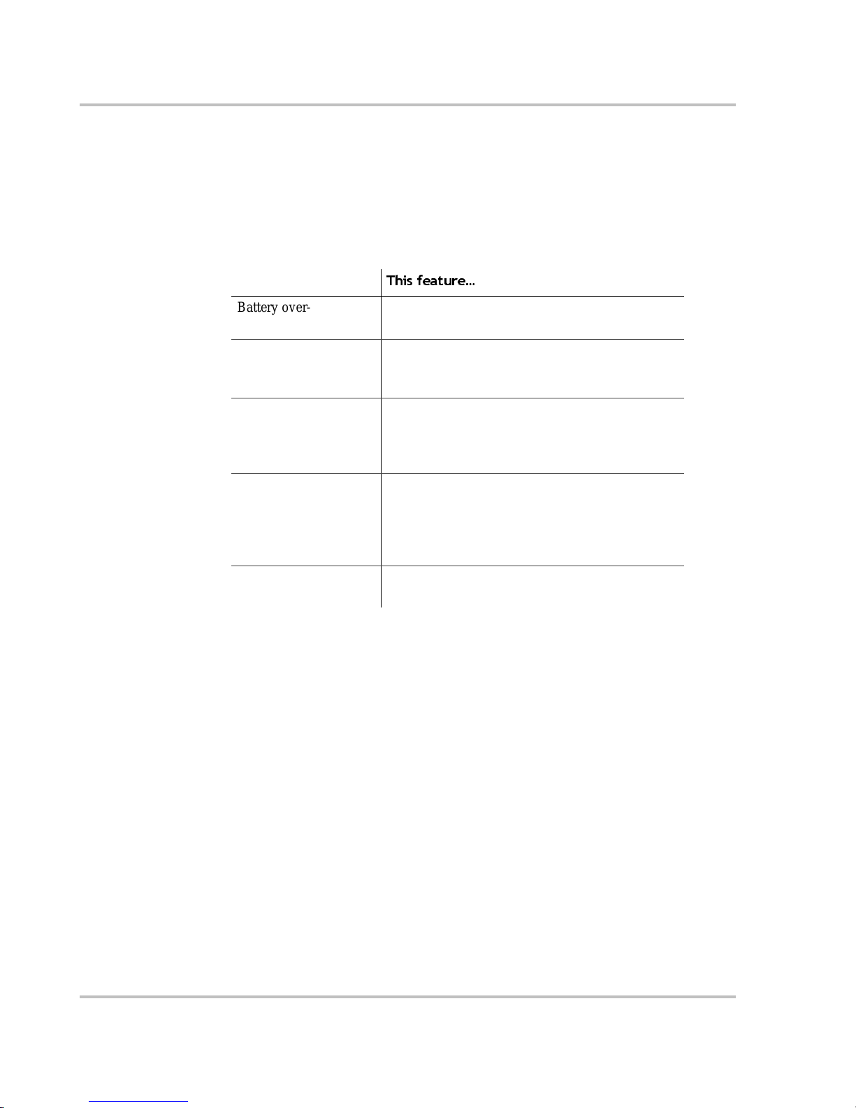
MS2000 is equipped with numerous protection features to ensure safe operation.
Protection feature
This feature…
Battery over- voltage
protection
Keeps the ba ttery voltage from getting too high in
charge mode. Shut s the inverter off in in vert mode.
Battery under-voltage
protection
Prevents inverter from discharging your batteries
too low . The inverte r doesn’t ru n if b att ery vo lta ge i s
too low.
Over-temperature
protection
Protects t he unit from ove rhe ating b y eithe r de ratin g
(charge mode) or by shutting down (invert mode).
See “Invert Power Derating vs Ambient
Temperature” on pag e A–6.
Automatic over load
protection
Protects the unit from excessive loads. The unit will
provide 5000 watts (2.5 times of the rated load) for
up to 5 seconds, and th en protect itself by shutting
down. See Specifications on page A–2 for more
information.
Short circuit protection Detects short circuits and protects the unit by
shutting it down.
Page 25
Introduction
975-0125-02-01 1–7
MS2000 Features
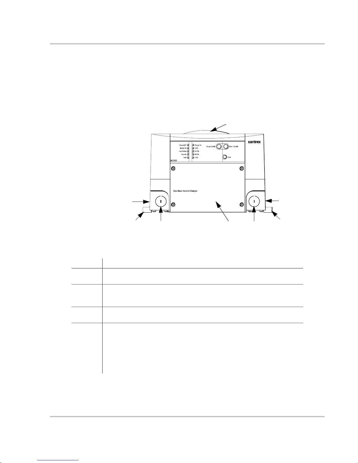
Front Panel Features
Before you begin to op erate the MS2000, revie w the front panel fe atures shown in
Figure 1-2 and des cribed i n Table 1-1. A detailed view of t he light s and butto ns on
the front panel is shown in Figure 1-3 and described in Ta ble 1-2.
Figure 1-2
Front Panel of the MS2000
Table 1-1
Front Panel Fea ture s
Feature Description
1 AC wiring compartment access panel provides access to the terminal block for
wiring the AC input and AC output.
2 AC knockouts provide access for AC input and AC output wiring. A total of four
knockouts are provided on the unit: two on the front and one on each side (not
shown).
3 Mounting flanges are used for mounting the unit. A total of six flanges are
provided on the unit.
4 Fans are located on the top of the unit and the bottom of the unit.
• T op external fan is an intake fan that activates when the internal temperat ure of
the inverter/charger increases. The fan speed varies with the internal temperature
and turns off when the inverter/charger cools down. (This internal temperature
may be caused by heat in the inverter/charger or by high ambient temperature.)
• Bottom internal fan (not shown) is an exhaust fa n and runs continuously if the
unit is inverting or charging.
2
3
2
1
2
4
2
3
Page 26
Introduction
1–8 975-0125-02-01
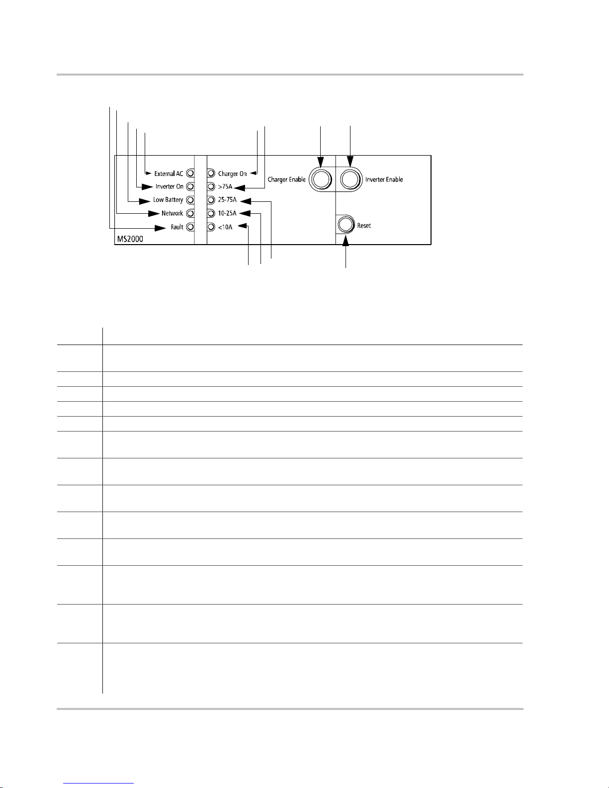
Figure 1-3
Front Panel Lights and Buttons
Table 1-2
Description of Front Panel Lights and Buttons
Feature Description
1 External AC light illuminates when you are conn ected to an AC source like the utility grid or a
generator and the AC is qualified.
2 Inverter ON light illuminates when the MS2000 is operating in invert mod e.
3 Low Battery light illuminates when the battery voltage is low.
4 Network light illuminates when there is activity on the network.
5 Fault light illuminates if a fault condition occurs .
6 Charger ON light illuminates when the main charger is in charge mode and is produ cing DC output to
charge your ba tteries.
7 >75A li ght illum inates when the tot al char ge curre nt of the mai n char ger and the Ec ho Char ger i s grea ter
than or equal to 75 amps DC.
8 25–75A light illuminates when the to tal char ge current of the main char ger and the Echo Charger is
greater than or equal to 25 amps DC and less than 75 amps DC.
9 10–25A light illuminates when the to tal char ge current of the main char ger and the Echo Charger is
greater than or equal to 10 amps DC and less than 25 amps DC.
10 <10A illuminates when the total charge current of the main charger and the Echo Charger is le ss than 10
amps DC.
11 Charger Enable button toggles between enab le (On) and disable (Off). When the ch arger is enabled, it
can produce DC output to charge your batteries. When the charger is disabled, it does not produce DC
output to charge your batteries, but still passe s AC input through to AC loads (if prese nt).
12 Inverter Enable button toggles between enable (On) and disable (Of f). When the inverter is enabled, it
can produce AC output to run your AC loads. When the inverter is dis abled, it does not produce AC
output to run your lo ads ; however, if qualified AC is present, the unit passes AC through to AC loads.
13 Reset button is used for se veral functions: to reset after a faul t, to perform a power on rese t, to wake the
MS2000 from Power Save mode or Hibernate mode. (See “System Modes” on page 2–6 for a
description of the different modes .) To perform a power on reset, hold the reset button for about 5
seconds. All front panel lights will illuminate to indicate the unit has rese t.
2
3
4
5
6
7
9
10
13
11
12
1
8
Page 27
Introduction
975-0125-02-01 1–9
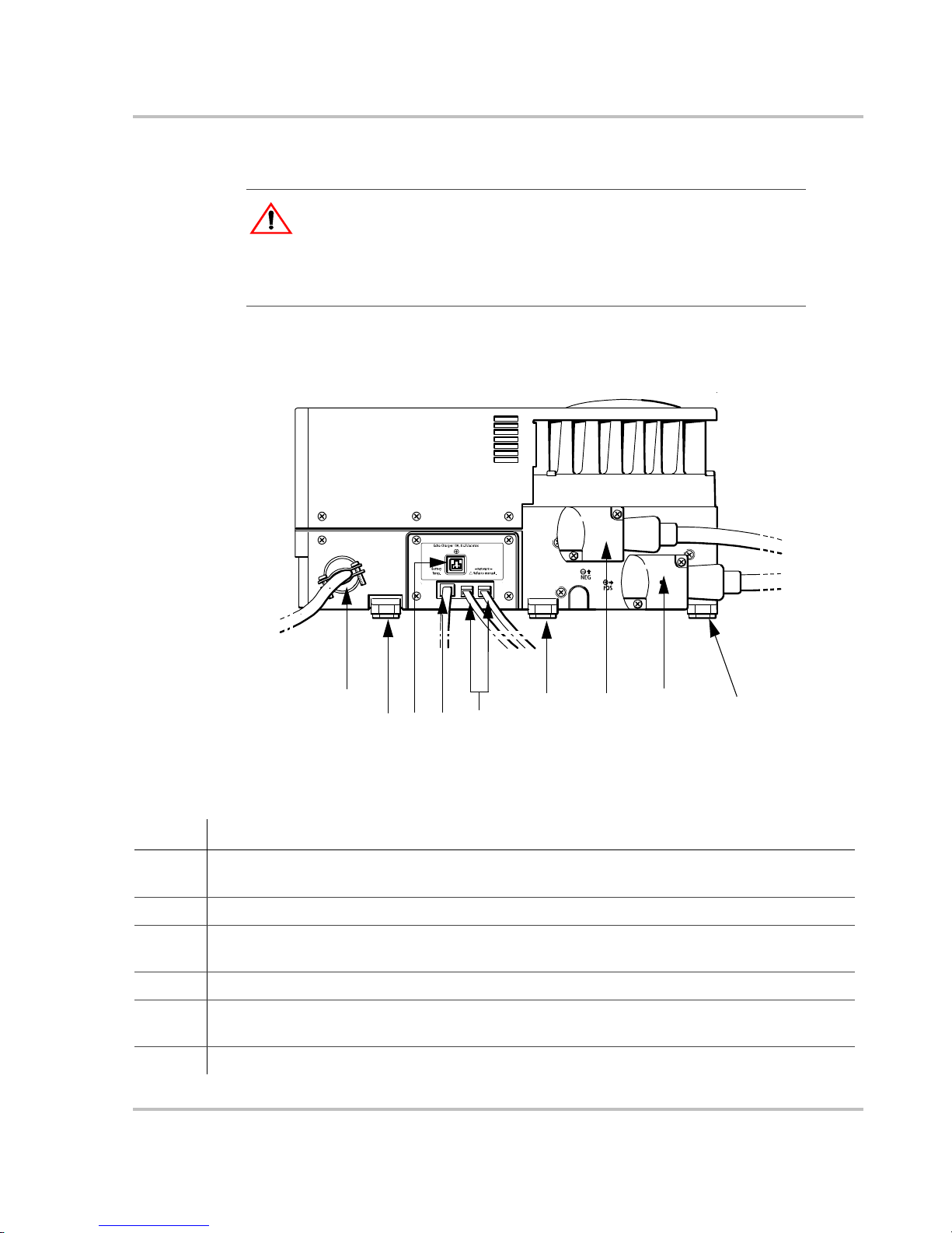
Side Panel Features
The side panel featur es with all c onnections c omple ted is shown in Figur e 1-4 and
Figure 1-5.
CAUTION: Equipment Damage
Connect only to other Xanbus compatible devi ce s. Although the cabling and
connectors us ed in this network system are the sam e as Ethernet con nec tors, this
network is not an Ethernet system. Equipment damage may result from
attempting to connect two dif ferent systems.
Figure 1-4
Completed Connections on Side Panel
Table 1-3
Description of Side Panel Features
Feature Description
1 AC knockout provides access for AC input and AC outpu t wiring (shown with strain-relief clamp
installed) . Th ere are four knockouts on the unit: two on the front and two on the sid e.
2, 6, 9 Mounting flanges are used for mounting the unit. A total of six flanges are on the unit.
3 Echo Ch a rg e r co nn e ct o r provides connection to the engine battery. Typically, this will be an engine
starting bat tery or an auxiliary battery for loads other than the inverter.
4 Battery temperature sensor jack provides connect ion for the battery temperature sensor .
5 Dual network jacks provide connec tion for network-enable d devices. (The number of connecti ons
depends on your layout. Your connections may not be the same as shown here.)
7 & 8 DC terminals – negative (black) (7) and positive (red) (8) —shown here with DC covers on.
!
2
9
3
7
6
5
8
1
4
Page 28
Introduction
1–10 975-0125-02-01
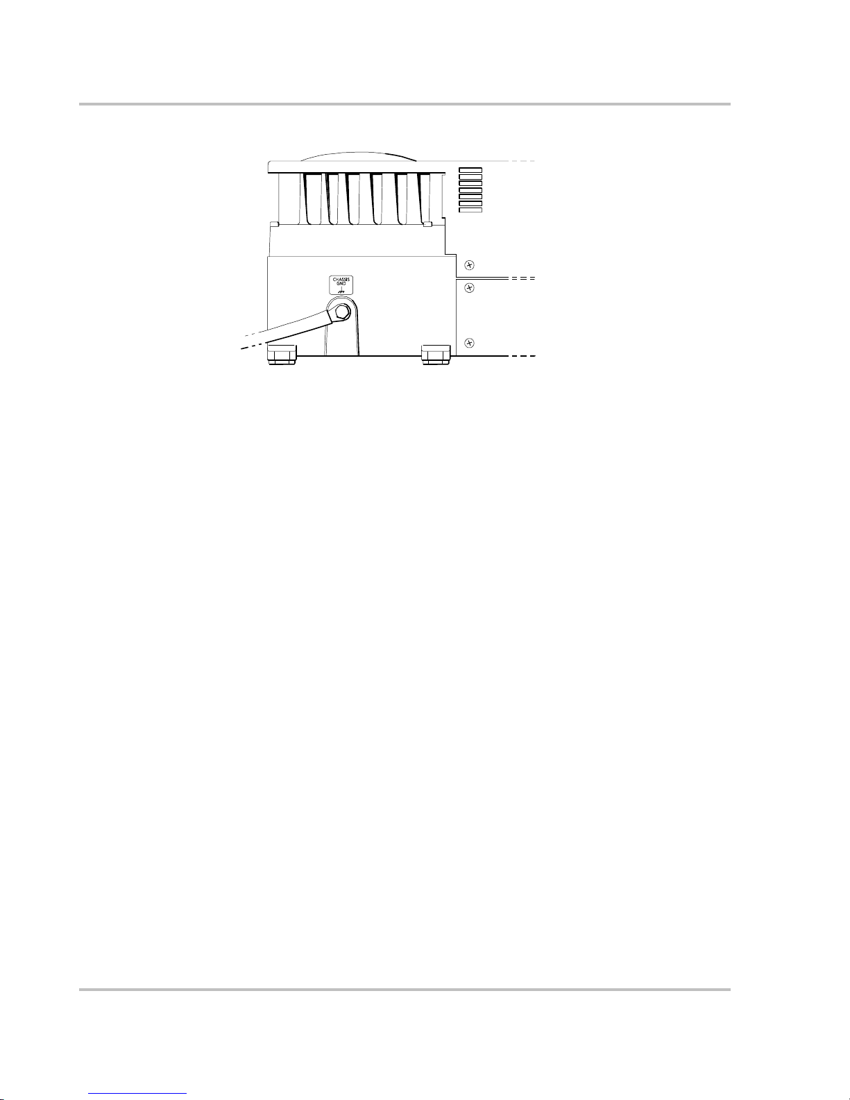
Figure 1-5
DC Grounding Completed
Page 29
Introduction
975-0125-02-01 1–11
DC Terminal Covers and Battery Temperature Sensor
DC Terminal Covers
T wo covers are supplied to prevent accidental contact with the cabling connectors
after installa tion. The red cover is for the positive cabling terminal, and the black
cover is for the negative cabling terminal.
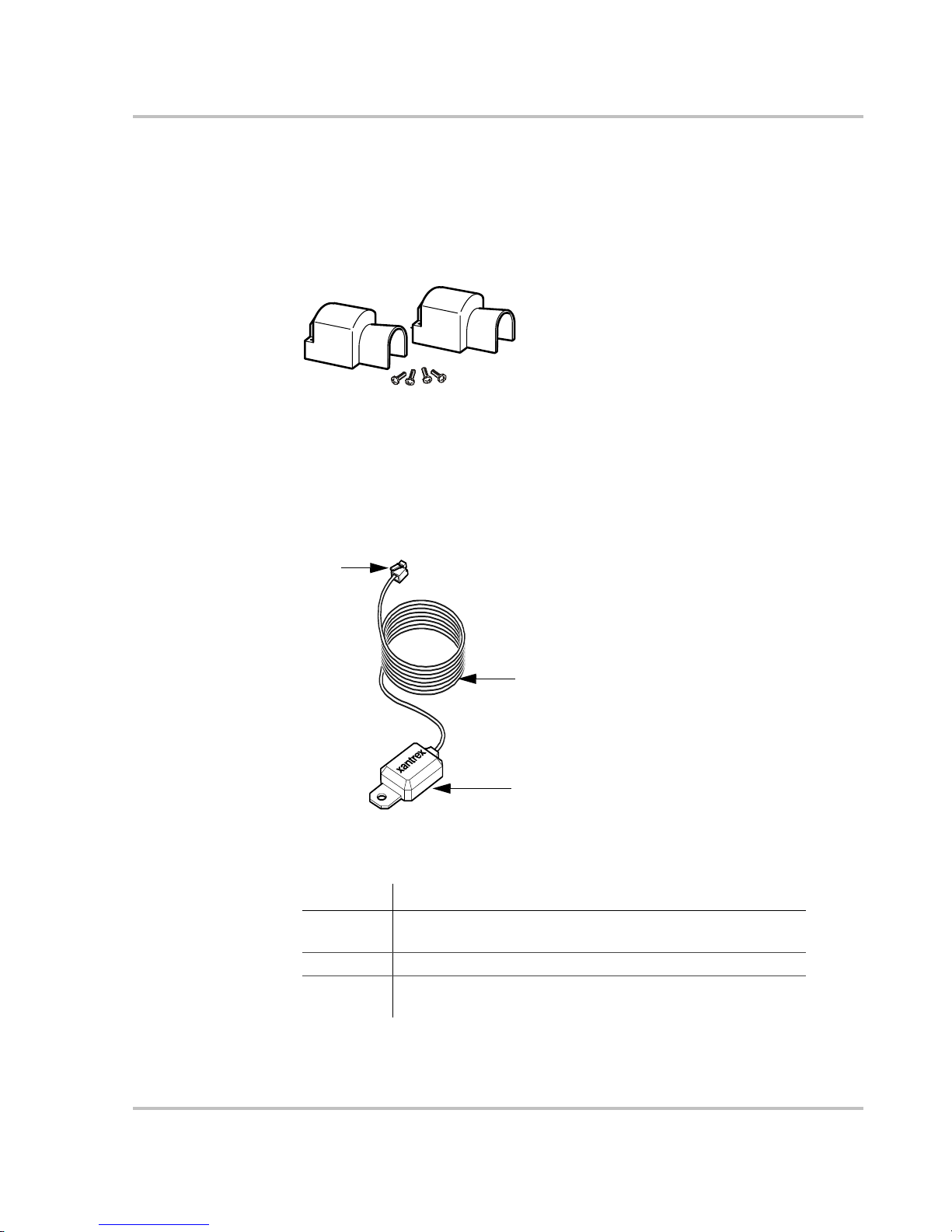
Battery Temperature Sensor
The battery temperatur e sensor continuously measures the temperature of the
battery and adj us ts the charg er o utpu t for a mor e accu ra te , temp e rat urecompensated charge.
Figure 1-6
Battery Terminal Covers
Figure 1-7
Battery Temperature Sensor
Table 1-4
Description of Battery Temperature Sensor Features
Feature Description
1 Sensor can be mounted on the side of the house battery case or
on the negative battery terminal.
2 Sensor cable is 25 feet (7.6 meters).
3 Connector plugs into the Battery Temp. jack (battery
temperature sensor) on the MS2000.
2
1
3
Page 30
Introduction
1–12 975-0125-02-01
System Accessories and Network Components
System accessories can be used with the MS2000 in a Xanbus system. The
System Control Panel (SCP) provi des configura tio n and monitoring capabil ity for
Xanbus-enabled devices such as the MS2000. Automatic Generator Start (AGS)
automatically starts and stops your generator. It continuously monitors your
battery system and thermosta ts and starts the generator if the battery state of
charge or t he volta ge r eaches pr eset lim its , or t he air condition er or he ater needs to
be run.
Table 1-5 provides the part numbers for the system accessories.
Consult with your local system designer to determine what network components
will be needed for your specifi c installation. Table 1-6 provides a list of network
components and part numbers. Pre-made cables are available in standard lengths
ranging from 3 feet to 75 feet.
These acces sor ie s and ne twork compo nen ts are avai l abl e fro m any aut hor iz ed
Xantrex dealer or at www.xantrex.com. Detailed information on planning and
installing your network is available in the Xanbus System Installation Guide. This
guide is available for downloading at www.xantrex.com
Table 1-5
System Accessories
Accessory Part number
System Control Panel (SCP) 809-0910
Automatic Generator Start (AGS) 809-0915
Table 1-6
Network Components and Part Numbers
Network Component Part Number
Network termination — Male (2 per pack) 809-0901
3-way network connector 809-0903
Network termination — Female (2 per pack) 809-0905
Network cable 3 ft. (0.9 m) 809-0935
Network cable 5 feet (1.5 m) 809-0936
Network cable 7 feet (2.0 m) 809-0937
Network cable 10 feet (3.0 m) 809-0938
Network cable 14 feet (4.3 m) 809-0939
Network cable 25 feet (7.6 m) 809-0940
Network cable 50 feet (15.2 m) 809-0941
Network cable 75 feet (22.9 m) 809-0942
Page 31
2
Operation
Chapter 2, “Operation” contains information and procedures for using
your MS2000. This chapter begins with a system startup check that
you carry out after installation and configuration to verify that the
MS2000 is operating correctly.
If you’re using the System Control Panel to operate or monitor the
status of the unit, also refer to the System Control Panel Owner’s
Guide.
WARNING: Restrictions on use
MS2000 Sine Wave Inverter/Charger shall not be used in connection with life
support syste ms or other medical equipment or de vices.
CAUTION
Read this chapter before operating the MS2000 Sine Wave Inverter/Charger.
Page 32

Operation
2–2 975-0125-02-01
Operating th e MS2000 with the Syste m Con trol Panel
The System Control Panel (SCP) provides operating, configuration, and
monitoring capability for your Xanbus system.
The System Control Panel:
• Monitors activity throughout your onboard power system.
• Displays the latest information about your inverter/charger, battery voltage
and current level, battery charge output, and generator start and stop activity.
• Displays the settings f or each Xanb us-enabled device in the system.
• Enables you to adjust the se ttings for each Xanbus-enabled device in the
system.
• Preserves all of its settings in non-volatile memory if system power is
interrupted. After power is restored, you don’t have to reconfigur e the SCP or
any of the Xanbus-enabled devic es connected to it.
This section provides information on operating the MS2000 with the System
Control Panel. Please refer to the System Control Panel Owner’s Guide for
complete information on using the System Control Panel.
Important:
Any MS2000 setting changed from the Syste m Control Pane l will
be saved if the unit is shut down by selecting Power S ave mode, Safe mode or
Hibernate mod e. See “System Modes” on page 2–6 for more information about
the different types of modes.
Page 33

Operation
975-0125-02-01 2–3
Using the System Control Panel
The System Control Panel has important featur es which you’ll want to be fami liar
with, as shown in Figure 2-1.
Display screen System information is shown on the display screen with an adjustable backlight.
Indicator lights Four indicator lights on the front panel indicate the oper ating sta tus of the Xanbus
system.
Push buttons Four push buttons allow you to select device menus and change or display
settings. The red System button toggles the System Control Panel and Xanbus-
enabled devices between Operate mode and Power Save mode. For more
information on the dif ferent system modes, see “System Modes” on page 2–6.
Figure 2-1
System Control Panel
Table 2-1
System Control Panel Features and Buttons
Feature Description
1 AC In/Charge light indi cates that qualified AC is present at
the input of the inverter/charger. When the MS2000 is
connected to a qualified AC source like the utility grid or a
generator, this light on the System Cont r ol Panel illuminates.
2 Inverter On light illuminat es wh en the MS2000 is enabled
(turned on).
3 Low Battery light illumi nates when the house battery v oltage
on the MS2000 is low.
4 Fault light indicates a condition that requires user attention
and intervention. The Fault light illuminates when any
Xanbus-enabled device connected to the network is in fault.
See “Faults and Warnings” on page 4–2 for the definitions of a
fault and warning.
5 Enter button
• Confirms selection of a menu item.
• Moves you to the next screen.
9
10
5
6
7
8
1
2
3
4
1
Page 34
Operation
2–4 975-0125-02-01
On Start Up
When the MS2000 is powered up or comes out of a reset state, all of the front
panel lights illumina te and remain on for a minimum of five seconds. After five
seconds, the lights remain illuminated until the front panel has status information
for all the lights.
The MS2000 is disabled e very time the unit is powered up. The inver ter must then
be enabled. When a function is disabled, it is not allowed to occur and if it is
occurring, it is te rminate d. Regardless of other conditions , the funct ion will not be
activated. For example, even if AC power is present, if the charger is disabled, the
unit will not charge .
When a function is enabled, it is allowed to occur but other conditions may have
to be met before the function is activated or turned on. For example, the charger
function on the MS2000 may be enabled, but it will not c harge unless qualified
AC power is pres ent .
Power On Reset
To perform a powe r on reset, hold the reset button on the front panel for about 5
seconds. All front panel lights will illuminate to indicate that the unit has reset.
6 Up arrow button
• Scrolls up one line of text.
• Incr ea ses a select ed va lu e .
7 Down arrow button
• Scrolls down one line of text.
• Decreases a selected value.
8 Exit button
• Cancels selecti on of a menu item.
• Returns you to the previous screen.
9 System button:
• T oggles a ll Xanbus-ena bled de vi ces on th e syste m bet ween
Operate mode and P ower Save mode. Se e “System Modes”
on page 2–6.
10 Screen displays menus, settings, and system information.
Table 2-1
System Control Panel Features and Buttons
Feature Description
Page 35
Operation
975-0125-02-01 2–5
System Start-up Check
To test the charging and inverting functions from the MS2000 front pane l:
1. Disconnect AC power from MS2000 AC input by opening the breaker or
disconnect. Press the Inverter Enable butt on on the MS2000. The Inverter On
light illuminates.
2. Place a load on the inverter. For example, plug a 100 watt light bulb into an
outlet that the inverter is powering and make sure it works. The inverter
should run the load using batter y power.
3. To test the charger, reconnect the AC input power to the AC input. The
Charger On light should illuminate after a brief delay. Any AC loads
previously powered by the inverter will also work at this time.
4. Remove the AC input power. The inverter/charger should transfer to invert
mode immediately. (The transfer relay will make a clicking sound and the
Inverter On light will illum inate.) Loads should continue to operate
uninterrupted.
To test the transfer switch:
1. If the inverter is enabled, press the Invert er Enab le button on the unit to
disable the inverte r function. The Inverter On light is not illuminate d.
2. Apply qualified AC power to the MS2000 input. After a brief delay, the
External AC light should ill uminate and AC loads on the output should
operate.
If any part of this procedure fails, determine the cause before using the
inverter/charger. Consult the “Troubleshooting” chapter starting on pa ge 4–1.
To test the Echo Charger:
1. Check the System screen on the System Control Panel and ensure the
MS2000 is in the Bulk or Absorption charge cycle.
2. From the MS2000 advanced menu on the System Control Panel, verify that
the Echo Charger is enabled.
3. If the Echo Charger is enabled, verify that the MS2000 advanced menu is
displaying the Echo Char ger current and voltage.
The current displayed will de pend on the voltage level of the house bank and the
voltage diff erence between the house battery bank and the engine batte ry.
WARNING
Review the “Important Safety Instructions” on page vii before operating the
inverter/charger.
Page 36

Operation
2–6 975-0125-02-01
System Modes
This section provides an overview of the four different system modes.
The system modes described in this section affect the performance and behavior
of the MS2000 and all other Xanbus-enabled devices on the Xanbus system.
You’ll have to change the system mode when putting your boat in storage, or
when installing a Xanbus-e nabled device.
You can change system modes using the System Settings menu on the System
Control Panel.
You can also use the red System button on the System Control Panel to put the
System Control Panel and all other Xanbus-e nabled devices into Power Save
mode only.
System modes are changed using the System Settings menu. The four system
modes are:
• Operate
• Power Save
• Safe
• Hibernate
Please read the section about each syste m mode to find out which mode is
appropriate for different conditions or situations.
Figure 2-2
System Control Panel
button
System
Page 37

Operation
975-0125-02-01 2–7
Operate Mode
Character isti cs In Operat e mod e, all co mm u nic at ions are enabl ed o n the Xan b us syst em . Al l
power conversion functions are enabled. Each Xanbus-enabled device is
monitoring and communicating its input.
The basic stat e of the Sy stem Co nt ro l Pan el is Oper ate mo d e. In O perat e mo de,
the System Control Panel communicates with other Xanbus-enabled devices and
displays all the network inf ormation which it is configured to display.
Whenever the System Control Panel or any othe r device on the Xanbus system is
powered on or reset, it will be in Operate mode.
P ow er Save M ode
Characteristics Power Save mode minimizes power draw by the System Control Panel and othe r
Xanbus-enabled device s on the Xanbus system. Power Save mode stops all
communication on the network, and disables the power conversion functi ons of
Xanbus devices. For example, in Power Save mode, the inver ter/charger will not
invert and an Automatic Generator Start will not start a generator.
When to use Use Power Save mode during periods when your power needs are minimal.
Putting the system in Power Save mode will help prese rve the charge in your
batteries during periods of minimal power usage.
Entering and exiting Power Save mode also serves as a “reset” command for the
system.
If there are active faults in the system, you cannot put the system into Power Save
mode. Clear any active fault, correct the condition that caused the fault, then put
the system into Power Save mode.
To ente r or exit Po w er Sav e m ode:
◆ Press and hold the System butto n on the System Co ntrol Panel for one second.
After you release the System button, the System Control Panel screen and
indicator lights will turn off.
Figure 2-3
Operate Mode
Page 38

Operation
2–8 975-0125-02-01
You can also enter or exit Power Save mode on the System Settings menu by
selecting Desire d Mode and scrolling to PowerSave as shown in Figure 2-4.
Returning to
Oper ate mode
If an inverter/charger supplies power to the network, applying AC input with
utility power or generator power au tomatically returns the system to Operate
mode.
Safe Mode
Characteristic s Selecting Safe mode stops the generator (if it is running) and puts the System
Control Panel (and all Xanbus- enable d devices) into Safe mode. While in Safe
mode, the System Control Panel remains power ed, “listening” to and reporting its
status to the network. Howe ver , the oupt ut power of all Xa nbus-e nabled de vices is
disabled and all inverting, charging, and generator starting activity stops. In Safe
mode, the MS2000 will not pass AC.
In Safe mode, the MS2000 continues to communicate, but the inverting and
charging functions are disabled.
When to use Use Safe mode when you are adding or removing devices from the network.
Authorized servic e perso nnel must also put the System Control Panel in Safe
mode before performing soft ware upgrades and diagnostics with the Xantrex
Diagnostic Tool.
If the System Control Panel is powered off while in Safe mode, it will be in Safe
mode when it is powered up again.
To return to Operate mode:
◆ On the System Settings menu, under Desired Mode, se lect “Operate.”
Figure 2-4
Power Save M ode
Operate
[Advanced]
CAUTION: Unexpected behavior
Before installing or removing a device on the network, put the network into S afe
mode. This prevents unexpected behavi our.
Page 39
Operation
975-0125-02-01 2–9
Putting the System into Safe Mode
When you are installing or removing dev ices from the Xanbus syst em, putting the
system into Safe mode prevents unexpected behavior.
To ente r Sa fe mo de :
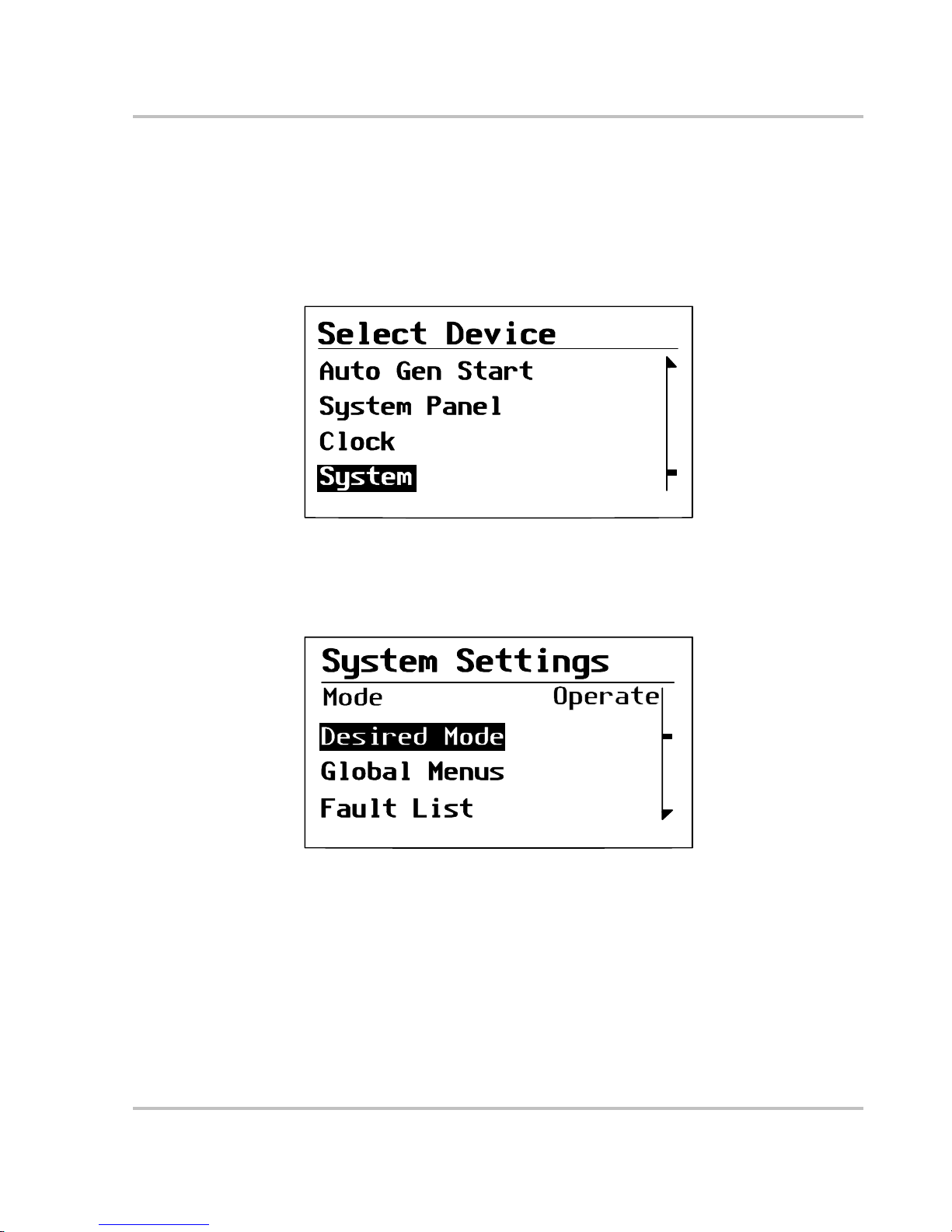
1. On the Select Device menu, use the down arrow button to highlight System.
The cursor on the right of the screen indi cate s where you are in the menu.
2. Press Enter.
The System Settings menu appears.
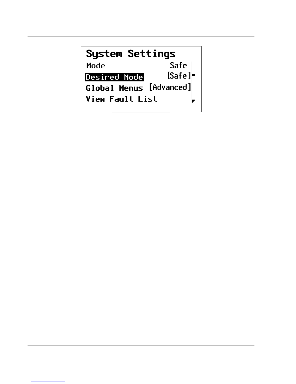
3. On the System Settings menu, with Desired Mode highlighted, press Enter.
4. Use the down arrow button to scroll through the other modes to select Safe
mode.
For more information on the different system modes: Operate, Power Save,
and Hibernate see “System Modes” on page 2–6.
Figure 2-5
Select Device Menu
Figure 2-6
System Settings Menu
Page 40
Operation
2–10 975-0125-02-01
5. Press Enter.
You are now in Safe mode.
6. Press Exit twice to return to the System Home Screen.
To exit Safe mode an d return to Operate mode:
1. On the System Settings menu, under Desired Mode, select “Operate.”
2. Press Enter.
Hibernate mode
Characteristics Hibernate mode removes network power from the System Control Panel and all
Xanbus-enabled device s on the Xanbus system. All operations are suspended
(including start ing and stopping the generator) until powe r is res tored to the
network. All Xanbus-enabled devices other than the MS2000 have no network
power.
When to use Use Hibernate mode when the Xanbus system is left unattended for long-periods
of time to prevent any unattended system activity and to prevent battery drai n
during long periods of inactivity.
The system will automatical ly enter Hibernate mode if it is in Power Save mode
for more than two hours.
If there are active faults in the system, you cannot force the system into Hibernate
mode. Clear any active faults, correct the condition that caused the fault, then put
the system into Hibernate mode.
Restoring power Onc e in Hibernate mode, the System Control Panel cannot ret urn the System to
Operate mode. You must restore power to the network by pressing the Reset
button on the MS2000 front panel for sever al seconds.
Figure 2-7
Safe Mode
Important:
To p revent any unatten d ed system activity, put the system into
Hibernate mode from the System Control Panel before putting your boat into
storage.
Page 41

Operation
975-0125-02-01 2–11
If an inverter/char ger suppli es power to the network , you can bring the system out
of Hibernate mode either by press ing the reset button on the inverter/c har ger front
panel or by applying AC input with utility powe r or generator power .
Page 42

Operation
2–12 975-0125-02-01
Operatin g in In v ert Mode
Once the inverter/charger is installed, you can operate it in invert mode.
To operate in invert mode from the front panel:
1. Press the Inverter Enable button on the MS2000.
2. If ex tern al AC is p res ent , the Extern al AC lig ht illum ina te s . If AC is pr esen t
and you want to run the inverter, remove AC so the inverter turns on.
Once the Inverter On light is on, the MS2000 inverter is ready to deliver AC
pow e r to the loads .
◆ To operate the inverter with the System Control Panel, refer to Chapter 3,
“Configuration”.
Load Sense Mode
The Load Sense m ode of t he MS2000 reduc es ba ttery power consumpt ion in or der
to conserve battery charge.
When the inve rter is en abl ed , the invert er /c harge r can be confi g ured to search for
an acceptable AC load. (It does this when you enabl e (turn on) “Load Sense” on
the MS2000 Advanced Menu on the System Control Panel and set the load sense
power threshold “Sense Below.”)
When the load sense feature is disable d (t urned off), the inverter is continuously
on. With load sense enabled, the inverter output consists of pulses if the unit
doesn’t detect a load that meets the load sense parameters. When an acceptable
load is detected, the inverte r output is turned on automatically and provides full
output power.
WARNING
Review the “Important Safety Instructions” on page vii before operating the
inverter/charger.
Important:
If you are having problems with an y of your loads, refer to
“Inverter Applications” on page 4–15.
Page 43

Operation
975-0125-02-01 2–13
Operating Limits for Inverter Operation
Power Output
Temperature The continuous output rating for the MS2000 is 2000 watts or 17 amps at 120
volts AC. The MS2000 can deliver this power in an ambient (surrounding)
temperature up to 122 °F (50 °C). Above this temperature, you must reduce the
power demand or the unit may shut down to protect itself against overheating.
As with all inverters, the amount of continuous power that the MS2000 can
deliver without overhe ating is limited by the ambient air temperature. The
MS2000 will operate and deliver its continuous power rating at higher
temperatures, but the ambient temperature as well as the input voltage from the
battery will limit the ext ent to which it can run continuously. Operating the
inverter/charger in conditions outside of power and te mperature limits will result
in thermal shutdown and/or sig nificantly decreased performance.
In addition, operati on in this range is outsi de the rati ngs covered by the regul atory
approvals of the product. See “Invert Power Derating vs Ambient Temperature”
on page A–6.
Difficulty on
starting loads
The inverter/charger should be able to operate all AC loads rated at or below its
power rating. Some high horsepower induction motors used in pumps and other
motor-opera ted equipment require very high surge currents to start, and the
inverter/charger may have difficulty starting these loads. See “Inverter
Applications” on page 4–15.
If you have problems starting certain loads, ensure that the:
• Battery connections a re tight and clean
• DC cabling is not longer than the recommended length. Refer to the MS2000
Sine Wave Inverter/Charger Installation Guide for this informati o n.
• AC wiring is of the recommended size. Refer to the MS2000 Sine Wave
Inverter/Charger Installation Guide for this information.
• Battery is of sufficient capacity and it is fully charged.
Page 44

Operation
2–14 975-0125-02-01
Operating in Ch arger Mode
To operate the MS2000 in charger mode from the front panel:
1. Connect AC input power.
House bank charging starts automatically when qualified AC power is
connected i f the charge r is enab l ed, o r the charg er is disab l ed but the Fo rc e
Charge enable ove rri d e is On. (See “Force Charge” on page 3–24.)
The Echo Charger operat es any time it is enabled and the main charger is
enabled and operating in bul k or absorption mode, and the house battery ban k
voltage is above 13.2 volts DC.
• The house battery bank is charged according to the two-stage or three-
stage formula you have selected on the System Control Panel. (See
“Battery Charging Ref erence for the Main Charger” on page B–1 for
more information on two-stage or thre e-stage charging.)
• You can interrupt the charge cycle any time you desire by disabling the
charger f rom the System Co ntrol Panel or by pressing the Ch arger Enable
button (on the front panel of the MS2000) so it is no longer illuminated.
• To maintain optimal performance in flooded batteries, an occasional
equalize cycl e may be required on the house battery only. See “Operating
in Equalization Mode” on page 2–18.
• While the house battery bank is being charged, you can monitor which
stage it is in from the System Control Panel.
◆ To operate the charger with the System Control Panel, refer to Chapter 3,
“Configuration”.
WARNING: Explosive Gases
Review the “Important Safety Instructions” on page vii before operating the
inverter/charger. During charging, batteries m ay generate explosive gases.
Thoroughly ventilate the areas around the batteries and ensure that there are no
sources of flames or spar k in the vicinity.
Study all battery manufacturer’s precautions such as removing or not removing
cell caps while charging and the recommended rates of charge.
Important:
If you are charging a non-sealed battery, ensure there is sufficient
distilled water in each cell. The battery acid should be at the level specified by
the battery manufacturer . This helps prevent over-heating and purges excessive
gases from the cells. Do not overfill. For a battery without cell caps, follow the
manufacturer’s rechargi ng in struct io ns carefully.
Important:
The Echo Charger doe s not operate when the main char ger is in Equalize
mode. Echo Charger operation is suspended in Equalize mode.
Page 45

Operation
975-0125-02-01 2–15
Echo Charger Operation
For the built-in Echo Char ger to operate, both the Echo Charger and the main
charger must be set to Enabled. By default, the Echo Charger is enabled by the
MS2000 to charge an en gine batte ry 10 sec onds af ter the main charger has en tered
Bulk or Absorption mode, and the house battery voltage is at 13.2 volts DC or
higher. The Echo Charger’s maximum charge current is 10 amps.
The Echo Charger stops char ging under the following condit ions:
• the maximum charge time of 8 hours is up.
• the current to the engine battery is less than 1 amp for more than 3 minutes.
• the engine ba ttery voltage is e qual to or greater than the house battery voltage.
Operation of the Echo Charger is shut down when:
• the MS2000 exits Absorptio n mode. The Echo C harge r doe s not ope rate when
the main charger is in Floa t or Equaliz e mode.
• you disable it from the System Control Pane l.
• it reaches a fault condition. See “Fault Messages” on page 4–9.
See “Echo Charger Specif ications” on page A–4 fo r more informat ion.
Enabling and Disabling Operation from the System Control Panel
You can enable or disable operation of the Echo Char ger in the MS2000 advanced
menu using the System Control Panel. By default, the System Control Panel
shows the MS2000 basic menu. To view the advanced menu, see “Selecting the
MS2000 Advanced Menu” on page 3–20.
To enable or disable the Echo Charger:
1. On the Select Device menu, highlight MS2000.
The cursor on the right of the screen indi cate s where you are in the menu.
2. Press Enter.
The MS 2000 me nu ap pears.
Figure 2-8
Select Device Menu
Page 46

Operation
2–16 975-0125-02-01
3. Use the down arrow button to scroll to Echo Chg.
4. Press Enter.
5. Use either arrow button to highlight Enabled and Disabled.
6. Press Enter.
7. Press E x it to ret u r n to the Se lect Devic e m enu.
Figure 2-9
Echo Charger
[30A]
[Enabled]
Max Chg Rate
[100%]
Figure 2-10
Echo Charger Enabled
[30A]
[Enabled]
Max Chg Rate
[100%]
Page 47

Operation
975-0125-02-01 2–17
Charger Operation with Battery Temperature Sensor
Since battery temperatur e is a key factor in optimal charging, the house battery
charger vol tage wi ll be adjusted ( automati call y and conti nuously ) acc ording t o the
actual batter y temperature to ensure that the house batte ry i s fully c har ged, but not
overcharge d. Fo r this reason, Xantrex has included a battery temperature sensor
(see Figure 2-11) with your MS2000 Sine Wave Inverter/Charger that allows the
main charger to pro vide this temperat u re-c o mpensated charg e formula. The Echo
Charger output bank is not temperature compensated.
The battery temperatur e sensor continuously measures the temperature of the
house battery and adjusts the main charger output for a more accurate,
temperature-compensated charge.
When batteries are cold, their chemical reaction is sluggish, meaning they don’t
absorb charge as easily. Thus a charge level optimized for room temperature will
not charge the batteries sufficiently if they are cold. The main charger must
compensate by increasing its voltage to achieve the compensated equiva lent of a
room temperature charge.
If the batteries are hot , the chemical reaction is hyperactive and they absorb
energy too easily; thus a standard room-temperature charge would tend to
overcharge a hot battery. Therefore, the main charger compensa tes by reduc ing its
voltage.
The battery temperatur e sensor automatically, and continuously, makes
adjustments to the main charger’s voltage setpoints to properly charge your
batteries. The actual charge compensation formula can be found on page A–3.
If a battery temperature sensor is not present, the MS2000 uses the cold, warm,
and hot settings. Charging may not be effective at extreme temperatures. See
“Main Charger Specifications” on page A–3.
Important:
It is normal to see a voltage th at is different than the specified
setpoint when charging if the batte ry case temperature is above or below 77 °F
(25 °C)
Figure 2-11
Battery Temperature Sensor
Page 48
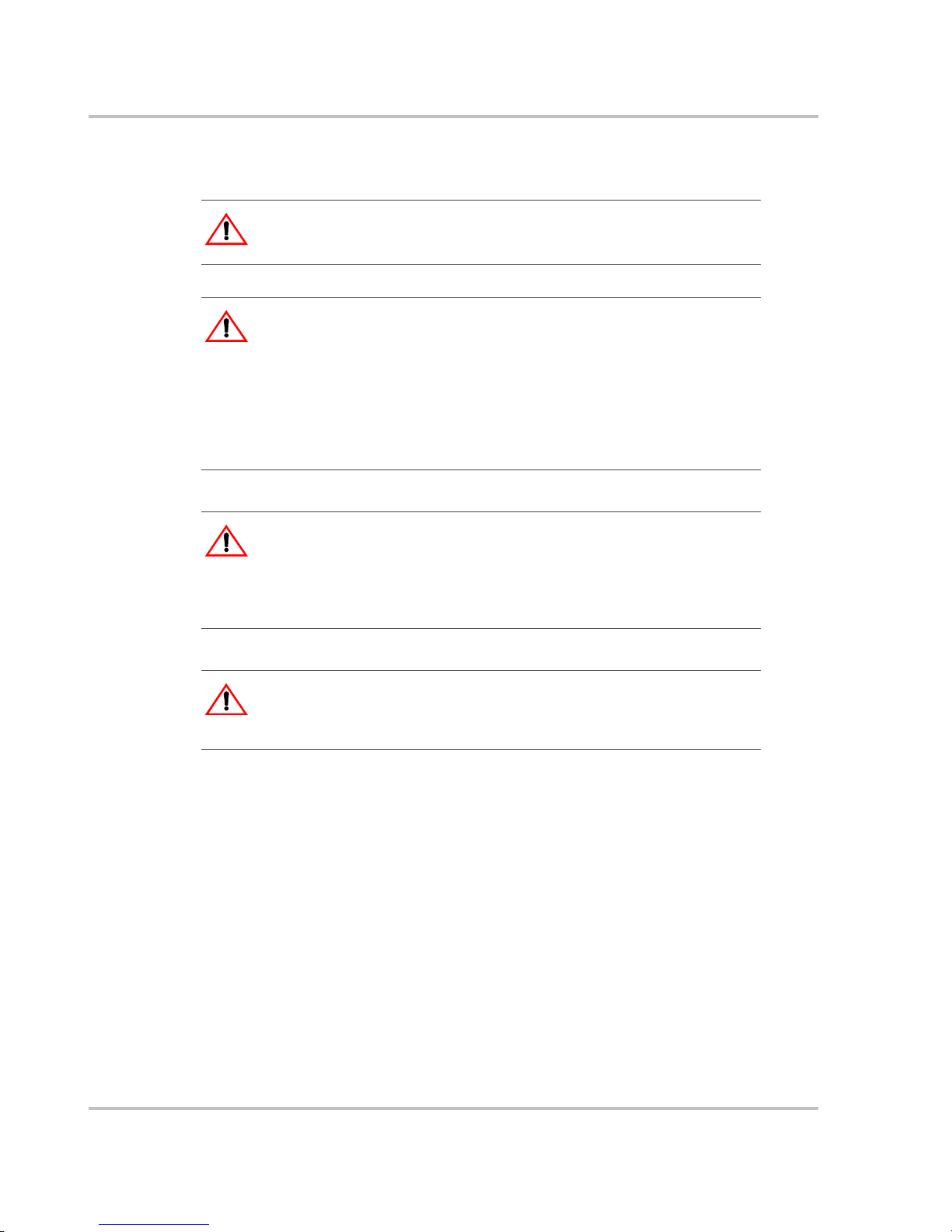
Operation
2–18 975-0125-02-01
Operating in Equ alization Mode
Follow the battery manuf actur er’s rec ommendat ions for equ alizing your batte ries.
As a guide, a heavi ly used floode d batt ery may need to b e equali zed o nce a m onth,
and a battery in light servic e may only need to be equaliz ed every two to four
months.
Measure the specific gravity (S.G.) of each cell using a hydrometer. For fully
charged lead-acid batterie s, the reading should be approximately 1.265. Low
specific gravity after charging or a 0.25 difference from cell to cell indicates the
need for equalization.
WARNING: Explosive gases
Equalization generates explosive gases. Ensure adequa te ventilation.
CAUT ION: Batteries may be damaged
Sealed lead-acid batteries and gel batteries must NEVER be equalized or
premature battery failure will resul t. Equalize mode is disable d if you have
selected “Gel” and “AGM” as the battery type.
Only flooded (wet) lead-acid batteri es should be equalized. As a general rule, do
not equali ze a battery unless there are provisions to add water to it and the
manufacturer recommends equalizati on.
CAUT ION: Batteries may be damaged
If carried out too frequently or done improperly, equalization can damage your
batteries. Never e quali ze a b atte ry more than ne cessa ry. Always check electrol yte
level before AND after equal iza tion. Fill with disti lled water per the battery
manufacturer’s recommendation.
CAUTION: Risk of damage to DC load equipment
Equalizatio n volt age ma y be as high a s 15.5 volt s DC. Disco nnect s ensiti ve l oads
from the battery befor e equ alizing.
Page 49

Operation
975-0125-02-01 2–19
Equalizing Batt eries
To equalize your batteries:
1. Turn off or disconnect a ll loads on the battery.
The voltage applied to the ba ttery during equalization may damage your
electronic eq ui pmen t . As well, eq ual izat i on won ’t proceed correctly if loads
are drawing current from the bat te ry.
2. Check electrolyte level.
Fill with distilled water if the electrolyte level is low.
3. To request the equalization charge, ensure the Charger switch is enabled, and
then scroll to the Equalize se tting on the System Control Panel.
4. In the MS2000 home menu, highlight Equaliz e, as shown in
Figure 2-12.
When you select On, the equalization confirmation warning appears, as shown in
Figure 2-13.
Important:
Equalization will be carried out after an absorption charge.
Equalization only runs for 60 minutes and may need to be restarted if the
specific gravity is still uneven.
Figure 2-12
Equalize On
[Enabled]
[10.0A]
[On]
[Flooded]
Page 50
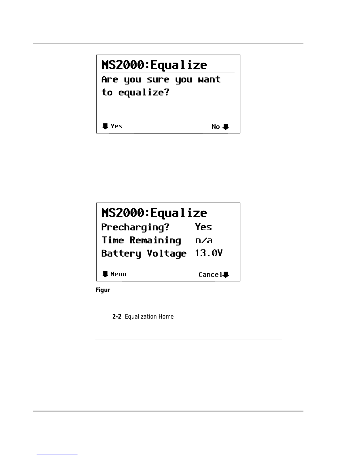
Operation
2–20 975-0125-02-01
Selecting Yes by pressing the Enter button takes you to the equalization system
home screen, as shown in Figure 2-14.
OR
Selecting No by pre ssing the Exit button on Figure 2-13 takes you to the MS2000
device screen.
See Table 2-2 for an explanation of the eq u ali ze h ome s cre en conten t .
Figure 2-13
Equalize Confirmation Warning
Yes
No
Figure 2-14
Equalization Home Screen
Menu
Cancel
Yes
n/a
13.0V
Table 2-2
Equalization Home Screen Content
Equalization Home
Screen content Exp lanation of items displayed
Precharging •“Yes”—precharging occ urs if batteries are not
fully charged before equalization. Batteries must
be fully charge d before equalization.
•“Done”—indicates the precharg e is complete or if
it was not required.
Page 51

Operation
975-0125-02-01 2–21
If you choose Yes, the equalization process is cancelle d and you are retur ned to
the MS2000 home menu.
0R
If you choose No and c ontinue wi th equa lization, the e qualizat ion home screen, a s
shown in Figure 2-14, appears.
5. When equalization is finished, check the battery electrolyte level. Top up as
necessary with distilled water only and recheck the specific gravity as
specified by the batter y manufac turer .
Time Remaining Indicates the time left for equalization. Equalization
runs for 60 minutes; time is counted down in 1
minutes increments until the Time Remaining
displays 0 min. (During a precha rge, the Time
Remaining displays “n/a”— not applicable.)
Battery Voltage Displays a range of 13.2 V to 18.0 with incre ments of
0.1V.
Menu Pressing Menu returns you to Select Device screen.
Cancel Pressin g Can ce l w il l dis pl ay a co nfir mat io n sc re en, as
shown in Figure 2-15, ask ing you to confirm that you
want to cancel equaliz ation.
Figure 2-15
Equalize Cancellation Warning
Table 2-2
Equalization Home Screen Content
Equalization Home
Screen content Exp lanation of items displayed
Yes
No
want
Equalization?
Page 52

Operation
2–22 975-0125-02-01
Terminating the Equalization Process
The equalization proce ss can be ter minated in three ways:
• user cancellation f rom the System Control Panel as shown in Figure 2-15
• inverter/cha rger cancellation if AC is removed or the charger is disabled
• successful completion of the equalization process
Operating Limits for Charger Operation
The maximum output current f or the MS2000 is 100 amps, spl it betwe en the main
charger (maxi mum 100 amps DC) and the Echo Charger (maximum 10 amps
DC). You can reduce the total output if you change the “Charge Rate” setting on
the MS2000 Advanced Menu or the maximum Power Share setting on the
MS2000 Basic Menu.
The charger can operate over an AC input range of 90–135 vo lt s AC. Th is is th e
default setting and can be adjust ed to 85–145 volts AC as a maximum range and
to 110–120 volts AC as a minimum range.This wide range allows the MS2000 to
charge your batt eries even when incoming AC voltage is less than ideal.
P ow er Sha r e
The MS 2000 charge r shar es incoming power w ith AC load s. T he A C loa ds h ave
priority, which means that the charger will reduce its output with la rge AC loads
and increase the output again when the AC load decreases. The regulatory
maximum for continuous AC loads is 80% of the breaker rating that the loads are
connected t o.
The MS2000 senses pass-through current going to the AC load. The difference
between the pass-t hrough (loa d) and 80% of the Power Share setti ng is the c urrent
that is available for charging the batteries.
For example, if the AC input of the MS2000 is from an AC panel with a 30A
breaker, the Power Share setting on the System Control Panel should be selected
as 30A. Based on this, the charge r will cont rol the charge current so that the tota l
current draw is equal to or less than 24A in this case. S hould the load current be
more than 24A, the charger output will reduce to 0A, but the MS2000 will
continue to su pply the loads. The MS2000 will continue to pass-through power to
the loads, even if the load current exceeds the Power Share setting. In this case, it
will be up to the user to remove/di sconnect loads if tripping the AC input breaker
supplying the MS2000 is to be avoided.
Important:
Changing the “Charge Rate” setting does not affect the Echo Charger’s
output current.
Page 53

Operation
975-0125-02-01 2–23
Monitoring th e MS 2000 Indica tor Lights
The ten indicator lights on the front panel show you the operating status of the
MS2000. A description of the lights is provided in Table 2-3.
If none of the front panel lights are on, see “Troubleshooting Reference” on
page 4–4.
t
Table 2-3
Front Panel Lights
Light
Illuminated Color Status Action or Status Item
External AC Green When the MS2000 is connected to a
qualified AC source or a generator, the
External AC light illuminates.
You can run your appliances from an
AC source like the utility grid or a
generator.
Inverter ON Green When the MS2000 is enabled (on) and
producing AC or load se ns ing, the
Inverter ON light illuminates. This light
is not illuminated if the unit is charging.
You can run your appliances from the
inverter.
Low Battery Yellow When the Low Battery light illuminates,
the batt er y level is low. The low voltage
shutdown leve l is adjustable from 10
volts DC (defaul t) to 13 volts DC. See
“Lo DC Volt” on page 3–22.
You can run your appliances but your
battery level is low. Charge your batte ry
or connect to an AC source or turn off
the inv er t er.
Network Green Indicates that ther e is activity on the
network.
Communication on the network
Fault Red A fault has occu rred on the network. Investigate and c lear the fault condition.
Charger ON Green When the MS2000 is in cha r ge mod e, the
Charger ON light is illuminated. If the
Charger ON light is off, the MS2000 is
not in any charge mode.
The main ch arger is active and charging
your batteries. Th e Charger ON light is
always illumi nated if charging, whether
the unit is putting out current or not.
>75A Green Indicat es that the tota l charge current of
the mai n cha r g er and t he E cho C har ge r is
greater than or equal to 75 amps DC.
These lights indicate the total amoun t of
charge current that the MS2000 is
producing.
25–75A Green Indicates that the total charge current of
the mai n cha r g er and t he E cho C har ge r is
greater than or equal to 25 amps DC and
less than 75 am ps DC .
10–25A Green Indicates that the total ch arge current of
the mai n cha r g er and t he E cho C har ge r is
greater than or equal to 10 amps DC and
less than 25 am ps DC .
<10A Green Indicat es that the tota l charge current of
the mai n cha r g er and t he E cho C har ge r is
less than 10 am ps DC .
Page 54

Operation
2–24 975-0125-02-01
Faults and Warnings
A fault affects the opera tion of the unit. A manual fault requires user intervention
by clearing the condition and then pressing the Reset button on the inverter/
charger’s front pan el. See the System Control Panel Owner’s Guide for
information on clearing faults from the System Control Panel.
A warning alerts you to a conditio n that coul d possibl y affec t operati on of the unit .
See “Faults and Warnings” on page 4–2 for more explanation on the difference
between faults and warnings.
Monitoring Status Messages on the System Control Panel
Refer to “System Menu Map” on page 3–3 of the Configuration chapter.
Page 55

3
Configuration
Chapter 3, “Configuration” contains information about all
configurable settings and procedures for the MS2000.
Page 56

Configuration
3–2 975-0125-02-01
Gener al Configu ration Informat ion
System Control
All changes to t he config urati on of th e MS2000 a re made wi th th e Syst em Control
Panel (SCP). The System Control Panel provides configuration and monitoring
capability for all Xanbus-enabled devices on the network.
The front panel of the MS2000 provides limited control, including reset; main
charger enable and disable; and inverter enable and disable. These functions can
also be controlled from the System Control Panel.
Page 57

Configuration
975-0125-02-01 3–3
System Menu Map
Figure 3-1 provides a map of how the menus are organized. The order of devices
appearing o n the System C ontrol Panel will vary, depending on the order in which
they’ve been connected to the network.
Figure 3-1
System Menu Map
Startup screen
Startup screen
Power Up
System scr een
System scr een
Select Device
menu
Select Device
menu
Inverter/Charger
menu
Inverter/Charger
menu
Clock menu
Clock menu
System Panel menu
System Panel menu
System Settings
menu
System Settings
menu
Enter
ExitExit
Enter
Device menus
Standby ChargingInverting Load SenseAC Bypass Equalize
Auto Gen Start menu
Auto Gen Start menu
Optional device. This menu will
appear if this device is installed.
=
Page 58
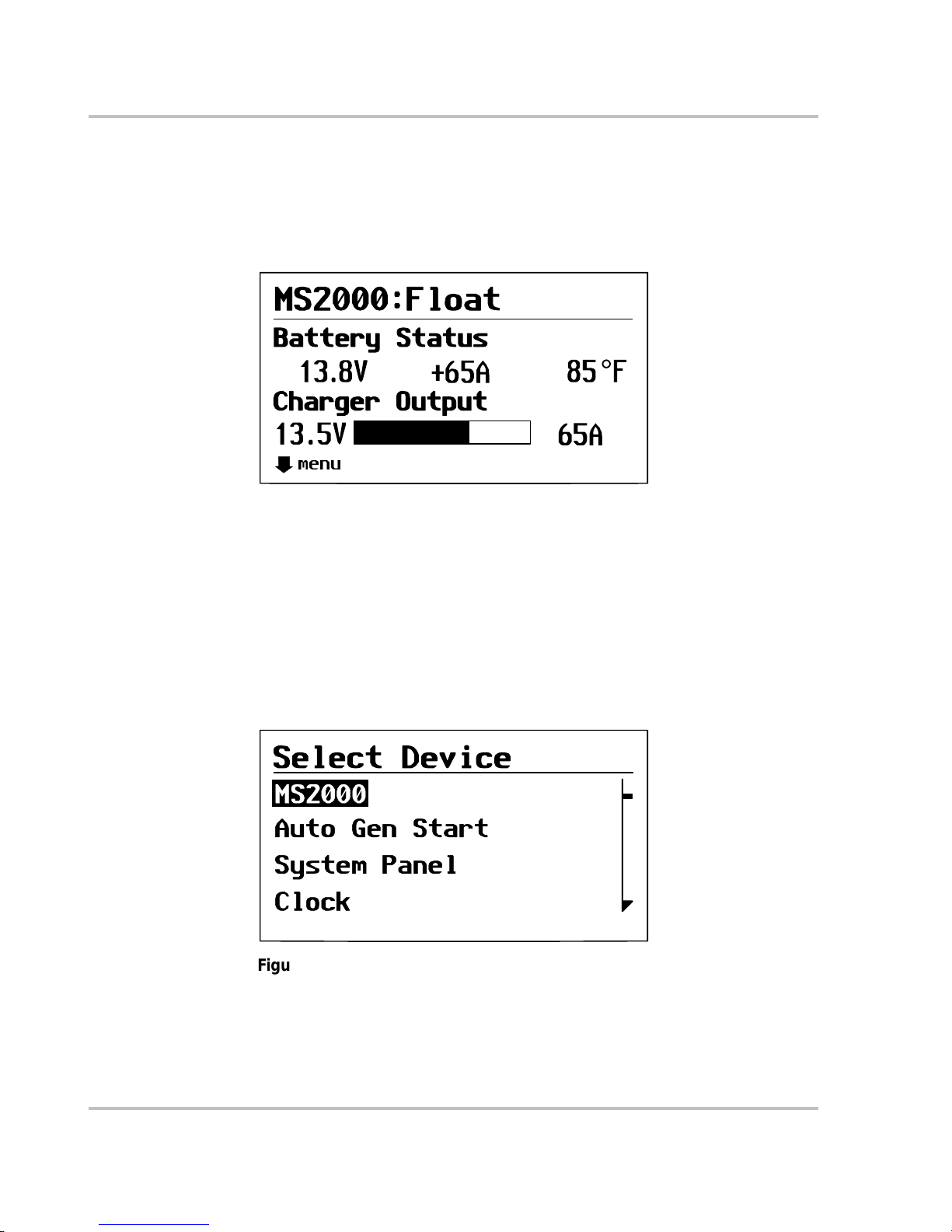
Configuration
3–4 975-0125-02-01
Viewing the System Screen
The System screen, as shown in Figure 3-2, is used to monitor system activity.
You cannot select or change any of the information on the System screen. If you
would like to view more detailed information, press Enter to go to the Select
Device menu.
Viewing the Select Device Menu
The Select Device menu is where you can view a list of all the Xanbus-enabled
devices in your power system. The number of items appearing on the Select
Device menu depends on how many devices are installed as part of your system.
To view the Select Device menu:
◆ On the System screen, press Enter.
The Select Device menu appears with MS2000 highl ighted.
Figure 3-2
MS2000 Float System Screen (Example)
menu
Figure 3-3
Select Device Menu
Page 59
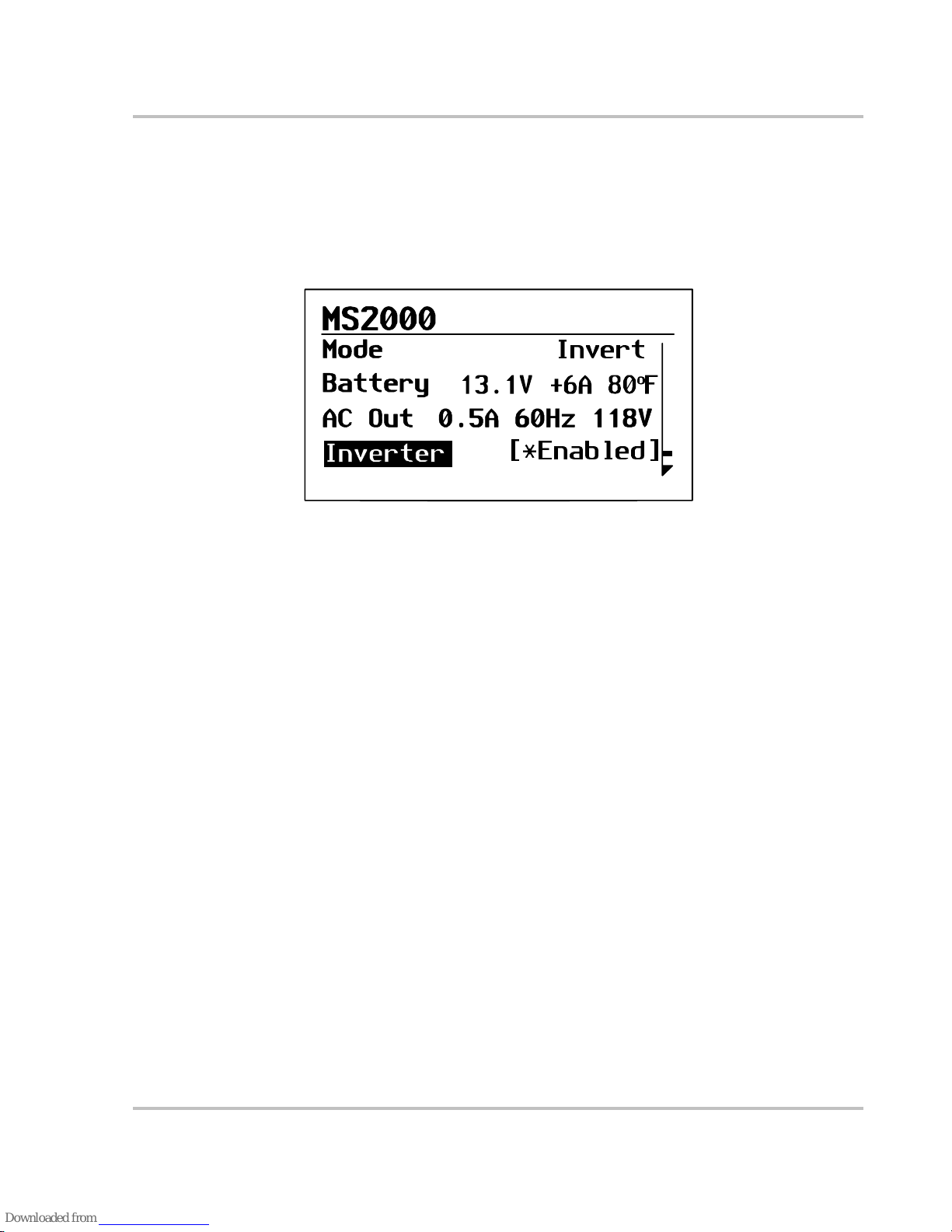
Configuration
975-0125-02-01 3–5
Selecting the MS2000 Basic Menu
To select the MS2000 from the Select Device menu:
1. On the Select Device menu, MS2000 appears highlighted.
2. Press Enter.
The MS2000 basic menu appears by default.
Selecting and Adjusting the Configur able settings
You can view MS2000 settings or change MS2000 settings from the MS2000
menu. Display settings show status items and cannot be changed. Configurabl e
settings are indicated by square brackets [ ] and can be adjusted, as shown in
Figure 3-4.
Follow these steps to change any MS2000 setting.
1. On the MS2000 menu, use the up arrow or down arrow butto n to highlight t he
setting you want to change.
2. Press Enter to highlight the value of that Configurable setting, indicated by
square brackets [ ].
The previously se t value a ppears wit h an ast erisk bes ide it, as shown i n Figure
3-4.
3. Use the up arrow or down arrow button to change the value. Holding down a
button lets you scroll thr ough values quickly.
4. Press Enter to select the value.
5. If you have another setting to change, return to step 1.
Or
If you have no more settings to change, press Exit to return to the Select
Device menu.
Figure 3-4
MS2000 Basic Menu in Invert Mode
Invert
[*Enabled]
Page 60

Configuration
3–6 975-0125-02-01
MS2000 Configuration Menus
The System Control Panel display s the MS2000 configuration menu in two
formats: basic and advanced. The System Control Panel shows the MS2000 basic
menu by default.
MS2000 basic menu list status infor mation and settings you may have to adjus t on
a routine basis. It provides access to basic control of the inverter/charger.
MS2000 advanced menu settings require that you understa nd and plan for the
changes you make. You may not have to adjust these settings as part of regular
operation. Advanced Menu can be enabled or disa bled through the System
Control Panel. See “Selecting the MS2000 Advanced Menu” on page 3–20.
To access the MS2000 configurations menus, select the MS2000 menu, as shown
in Figure 3-5.
Figure 3-5
MS2000 Menu
Invert
[Enabled]
Page 61

Configuration
975-0125-02-01 3–7
The MS2000 menu structure is shown in F igure 3-6. The first four lines a ppearing
in both menus: Mode, Battery, AC Input or AC Out, are status items only and are
not configurable. Echo Chg Out in the Advanced Menu is also a status item and is
not configurable.
-
Figure 3-6
MS2000 Menu Structure — Overview
Page 62
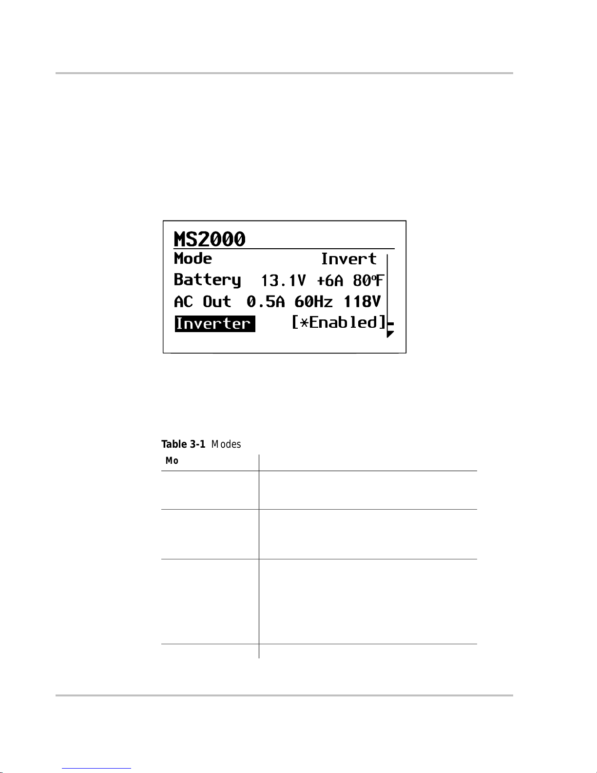
Configuration
3–8 975-0125-02-01
MS2000 Device Menu
The MS2000 device menu displays status information on the different modes of
the inverter/charger. The first three lines of the device screen displays dynamic
content that changes, depending on what operation mode that the MS2000 is in.
Status in formation is not configur able; configurable items are indicated by square
brackets [ ]. An asterisk indicates the value that was previously set.
For example, in Figure 3-7, the MS2000 is in invert mode with AC current going
out.
Mode
The first line indicat es which mode that the MS2000 is in. Table 3-1 defines the
different mod es.
Figure 3-7
Invert Mode - Basic Menu
Invert
[*Enabled]
Table 3-1
Modes
Mode Description
Bulk Charge The fi rst s t age o f t hre e- sta ge ba tt ery c har gi n g. Cu rre nt
is supplied to the batteries at a constant rate while
voltage gradually rises.
Absorption Charge The second stage of three-stage bat tery charging.
Voltage re mains constant and current red uces as the
battery becomes charged. This ensures complete
charging.
Float Charge The thir d stage of thr ee-stag e battery charging. After
batteries reach full charge, charging voltage is
reduced to a lower level to prevent gassing and to
prolong batter y li fe. This stage i s ofte n referr ed to as a
mainten anc e ch ar ge . Rath er than ch ar gi n g a bat ter y, it
keeps an already-charged battery from disch arging
while providing load current.
Invert The MS2000 is converting DC power to AC power.
Page 63
Configuration
975-0125-02-01 3–9
Battery
The second line of the device scr een indic ates t he status of the house ba tter y bank.
This line displays the voltage (V); the current (A) as either (+) positive amps
(indicating that the battery is charging) or (–) negative amps (indicating the
battery is dischar ging because you’re inverting), and the battery temperature in
either °F or °C.
For the status of the engine battery, see “Echo Chg Out”.
AC Input
When the MS2000 is in charge mode, this line indicates whether you have AC
input from the utility grid or from a generator. This line shows the values for
current (A), the frequency (Hz), and the A C vo ltag e in (V) .
AC Out
This line is displayed whe n the MS2000 is in invert mode or in AC bypass mode.
This line indicates the AC output and shows the values for current (A), the
frequency (Hz), and the AC voltage in (V).
Echo Chg Out
This line appears only in the MS2000 Advanced Menu and displays the status of
the Echo Charger. If the Echo Charger is enabled and operating, DC output
current (A) and voltage (V) are displayed. If the Echo Charger is disabled or not
operating, the line will display “Inactive”.
AC Bypass AC input from an AC source like the utility grid or
from a generator is all owed to pass through the unit to
operate connected AC loads. The charger is not
enabled but AC is qualified and passed through the
unit.
Equalize To improve the life and performance of a non-sealed,
flooded (or wet) battery, the MS2000’s multi-stage
charging cyc le includes a manual equalize mode that
can be used if recommended by th e bat tery
manufacturer.
Load Sense In order to minimize power draw from the battery , the
invert er w i ll periodically ch eck if a load is co nnected
when the inverter is enabled.
Table 3-1
Modes
Mode Description
Page 64
Configuration
3–10 975-0125-02-01
MS2000 Menu (Basic)
The MS2000 basic menu indicates the status of items and lists settings that you
may have to adjust on a routine basis.
If advanced menu is enabled, scroll through the MS2000 advanced menu items
until Basic Menu is highlighted and press enter.
This section describes each display item and configurable item in detail with an
example of the line ite m. Each it em is descri bed in terms of i ts purpose , whether it
is a display or configurable setting, when to use, and the outcome of changing a
setting.
Inverter
Configurable sett ing This setting lets you enabl e or disable the inverter. In the example shown, the
inverter is enabled. For an explanation of enable and disable, see “Te rminology”
on page C–1.
When to use Enable the inverter when you would like to have AC power from the inverter.
Outcome The inverter is enabled. The inverter provides power from the batteries unless
qualified AC input power is present.
Inverter [Enabled]
Value Default
Enabled
Disabled Disabled
Page 65

Configuration
975-0125-02-01 3–11
Charger
Configurable setting This setting lets you enab le or dis able the oper ation of the main cha rger. When the
main charger is enable d and AC is connected to the input, the house battery bank
will charge. The Echo Charger will charge if it is enabled separately in the Echo
Charger menu. See “Echo Chg” on page 3–18.
The Disabled set ting of this item will di sab le the main c harg er a nd can be disabled
at any time during the charge cycle.
If the char ger is enabled and the AC is not qualif ied as good, then the charger will
not operate until AC qualifie s as good.
The charger can be enabled or disabled from the front panel of the MS2000 or
from the System Control Panel (SCP). In the example shown, the charger is
enabled.
Outcome Use the default Enabled setting to ens ure batte ries are alwa ys being charge d when
connected t o an AC sou rc e. Di s ablin g the charg er will turn off the charge
function. Then the next time qualified AC power is connected, the charge r is
automatically enable d and charging will begin, if Force Charge is enabled. If
Force Charge is not enabl ed, charging will not occur until the Charger setting is
changed from disabled to enabled.
See “Force Charge” on page 3–24 for more inform at ion on this feat ure.
Important:
Both the main cha rger and the Echo Char ger must be set to enabled for the
Echo Charger to operate.
Charger [Enabled]
Value Default
Enabled Enabled
Disabled
Page 66
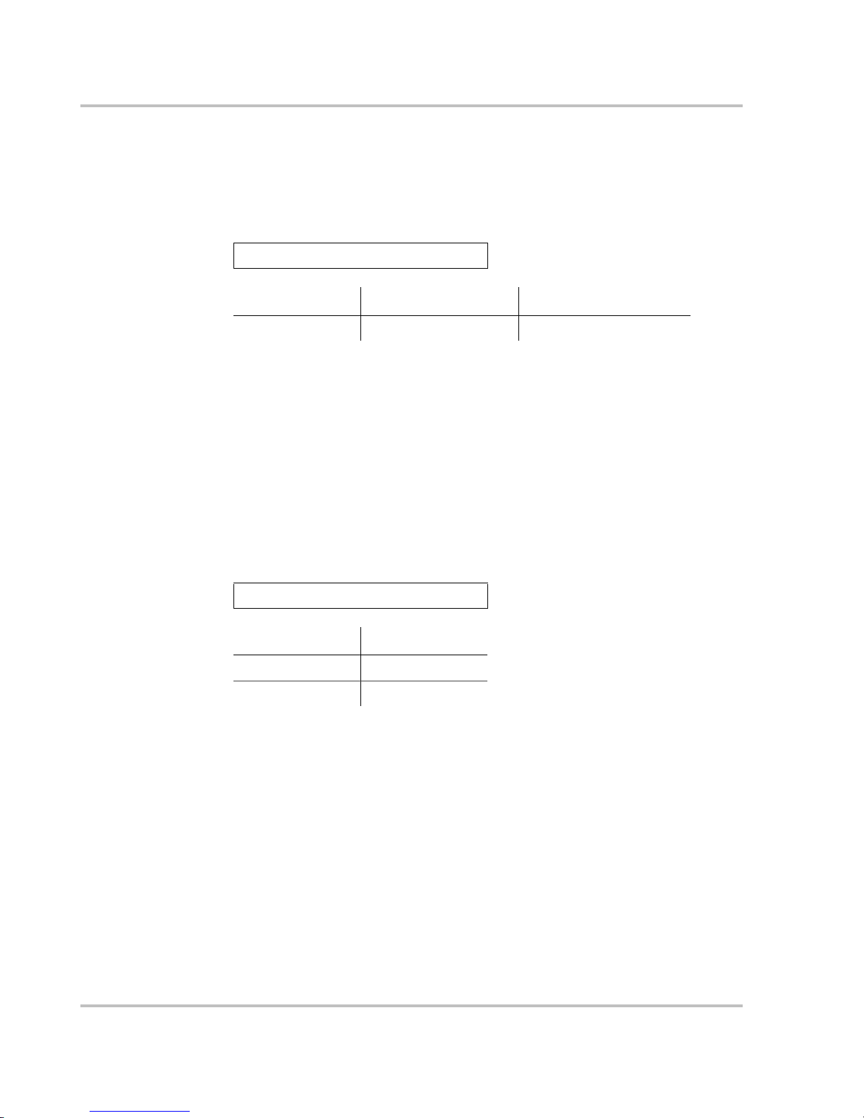
Configuration
3–12 975-0125-02-01
P ow er Sha r e
Configurable setting Power Share is a confi gurabl e setting that you se t to match to t he breake r ratin g on
the AC input. This setting is used to ensure that the charger limits its out put to try
to prevent nuisa nce trip ping of the AC input b reaker due to the total cur rent drawn
by the charger and your other AC loads. See also “Power Share” on page 2–22.
When to use Set the Power Share setting to match the AC input breaker. Use this setting when
connectin g to an AC s our ce. If usi ng mul t iple A C so ur ces v ia an AC tran s fer
switch, adjust this setting to the smaller AC breaker size.
Outcome Setting the value higher tha n the AC source’s external breaker could cause the
external breaker to trip.
Equalize
Configurable setting This setting le ts y ou enable or di sable char ger equaliz ation, on ly i f the battery type
is flooded (or wet ).
Equalization can be turned on (enabled) or off (disabled).
When to use Review the section, “Operating in Equalization Mode” on page 2–18 before
adjusting this setting. This menu item is displayed if the battery type allows
equalization.
Power Share [10A]
Range of values Increment Default
5 to 50 amps 5 amp increments 30 amps
Equalize [Off]
Value Default
On
Off Off
Page 67
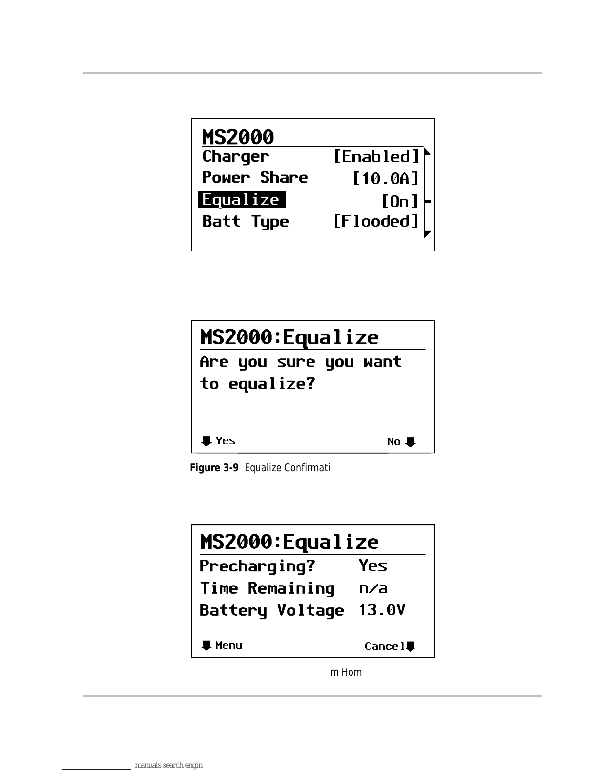
Configuration
975-0125-02-01 3–13
In the MS2000 home menu, highlight Equalize, as shown in Fi gure 3-8.
When you select On, the equalization confirmation warning appears, as shown in
Figure 3-9.
Selecting Yes takes you to the equalization system home screen, as shown in
Figure 3-10.
Figure 3-8
Equalize On
[Enabled]
[10.0A]
[On]
[Flooded]
Figure 3-9
Equalize Confirmation Warning
Yes
No
Figure 3-10
Equalization System Home Screen
Menu
Cancel
Yes
n/a
13.0V
Page 68

Configuration
3–14 975-0125-02-01
Batteries must be fully ch arge d before e qualiz ation . If th ey are not fully cha r ged, a
precharge occurs. During precharge, the T ime Remaining appears as “n/a”—not
applicable. When the equalization process begins, Time Remaining appears as a
value between 60 min and 1 min.
You can cancel the equalization process by select ing Cancel, in which case Figure
3-11 appea rs, asking if you want to cancel equalization.
If you choose Yes, the equalization process is cancelle d and you are retur ned to
the MS2000 home menu.
If you choose No, the equalization home screen as shown in Figure 3-10 appears.
Figure 3-11
Equalize Cancellation Warning
Yes
No
want
Equalization?
Page 69

Configuration
975-0125-02-01 3–15
Batt Type
Full name Battery Type
Configurable sett ing Select the type of battery for your house bat tery from Flooded, AGM, Gel or
Custom. If a battery temperatu re sensor is not present, the MS2000 uses cold,
warm or hot settings with the hot setting a s the def ault.
When to use This setting is adjusted for the type of house battery you have. It is important
during configuration to choose the correct setting (battery type) to optimize the
charge algor ithm for your battery and to properly enable or disable equalization.
See “Battery Cha rging Re fer en ce fo r the Mai n Ch arge r” on page B–1 for more
information.
The custom setting is selected to get the battery settings programmed by the
dealer.
Batt Size
Full name Battery size
Configurable sett ing This feature lets you sele ct the siz e of the house battery bank.
When to use Adjust this setting to match the amp-hour capacity of the house battery bank.
Outcome Reduces the main charger outp ut curr ent to protect against charging sm all er
battery banks too aggressively. This setting charges batteries appropriately based
on the amp-hour capacity of the house battery bank.
The Echo Charger is optimized to produce a maximum 10 amps DC output and is
not affected by this se tting. See “Battery Charging Re ference for the M ain
Charger” on page B–1 for more information.
Batt Type [Flooded]
Value Default Battery
Type
Flooded F looded
Custom
AGM
Gel
Important:
The Echo Charger is not affected by this setting.
Batt Size [440 Ah]
Range of values Increment Default
50 Ah to 2000 Ah 10 Ah 440 Ah
Page 70
Configuration
3–16 975-0125-02-01
Clear Faults
Purpose Clear Faults is a command which clears all active faults in the MS2000. When
faults are cleared, the device will resume normal operation. If the faul t condition
still exists, the fault will reoccur.
Clear Faults
Value Effect
Yes Faults ar e cle ar ed
No No action
Page 71

Configuration
975-0125-02-01 3–17
MS2000 Menu (Advanced)
The MS2000 advanced menu lists settings that provide you with additional
control over MS2000. However, you may not have to adjust these settings as part
of regular operatio n. For a listing of advanced menu items, see “MS2000 Menu
Structure — Overv iew” on page 3–7.
These settings are only vis ible if Advanced Menu is selected. To select the
MS2000 Advanced Menu, see “Selecti ng the MS2000 Advanced Menu” on
page 3–20.
In addition to several it ems from the basi c menu, the MS2000 advanced menu
contains the followi ng sub-menus and commands:
• Configure Inv/Chg (Configure Inverter/Charger)
• Cfg AC Limits (Configure AC Limits)
• Dev Info (Device Info)
When you select a sub-menu and press Enter, a list of menu items appears.
This section describes each display item and configurable item in detail. Each
item is described as a display or configurable setting, when to use the setting, and
the outcome of changing a setting.
Inverter
See a description of this featur e on page 3–10.
Charger
See a description of this featur e on page 3–11.
P ow er Sha r e
See a description of this featur e on page 3–12.
Configure In v/Chg (Configure Inverter/Charger)
Cfg Inv/Chg is a sub menu c ommand. If you selec t thi s item, you’ll access a list of
sub-menu items. See “Configure Inv/Chg Menu (Configure Inverter/Charger
Menu)” on page 3–22.
Page 72

Configuration
3–18 975-0125-02-01
Max Chg Rate
Full name Maximum charge rate
Configurable setting The actual battery char ge ra te is de termined by t wo things . Fir st, the MS 2000 uses
the house battery Batt Size setting (C) on page 3–15 divided by 5 (C÷5) to
determine that maximum total charger output. This value is then modified by t he
charge rate set ting.
For exampl e, if the hou se battery bank size is set to 300 Ah a nd the charge rate
was set at 100%, the calculation would be: 300 ÷ 5 or 60 amps × 100% which is a
60 amp charge rate. If the charge rate is adjusted to 50%, the resulting charge rate
would be 30 amps (60 amps × 50%) total.
Even though you can set a house battery bank size of 2000 Ah, where C÷5 is 400
amps, the MS2000 would still charge at 100 amp, the maximum total charge rate.
When to use Displayed only if in charger mode when you wish to control the m aximum charge
rate to your batteries.
Echo Chg
Configurable setting This setting lets you enable or disable the Echo Charger function.
When to use The MS2000 has a maximum total charge rate of 100 amps, split between the
main charger and the Echo Charger. The Echo Charger uses a maximum of 10
amps DC, which is not affected by the Max Chg Rate setting.
When the Echo Charger is enabled, 10 amps of the 100 amp charge output could
be delivered to the engine batte ry and 90 amps could be delivered to the house
battery bank. You must disable the Echo Charger if you want 100 am ps of charge
current going to the house battery bank.
For example, if the bank size is 500 Ah or more and the Max Chg Rate is set to
100%, the calculation would be: 500 ÷ 5 or 100 amps × 100%. The total output
would be 100 amps with 90 amps going to the house battery bank and 10 amps to
the engine battery.
Max Chg Rate [100%]
Range of values Increment Default
10% to 100% 10 100%
Echo Charger [Enabled]
Value Default
Enabled Enabled
Disabled
Page 73

Configuration
975-0125-02-01 3–19
In another example where the bank size is 500 Ah or more and the Max Chg rate
is set to 50%, the calculation would be: 500 ÷ 5 or 100 amps × 50%. The total
output would be 50 amps with 40 amps going to the house battery bank and 10
amps to the engine battery.
Load Sense
Configurable sett ing This setting lets you enabl e or disable the load sensing function.
When to use Enable this setting if you want the inverter to conserve battery power when there
are small loads or no loads applied.
Outcome A small load like a c lock display on a microwave may not get power. When loads
are below the load sense threshold, the inverter will turn off the output to save
battery power.
Equalize
See a description of this featur e on page 3–12.
Clear Faults
See a description of this featur e on page 3–15.
View Device Info
For more information on this sub menu, Device Information, see “View Device
Info Menu (Device Information Menu)” on page 3–27.
Basic Menu
Purpose Selecting Basic Menu takes you back to the basic menu of the MS2000 only.
Advanced menu items will no longer be visible on the System Control Panel.
When to use Use this setting when you want to return to the basic menu of the MS2000.
Load sense [ On]
Value Default
On
Off Off
Page 74

Configuration
3–20 975-0125-02-01
Selecting the MS2 000 Advanced Menu
The System Control Panel shows the MS2000 basic menu by default. If you
would like to view the advanced menu, you must go to the System Settings menu
and select Global Menus.
To select the MS2000 Advanced Menu:
1. On the Select Device menu with System highlighted, press Enter.
2. Scroll with the down arrow button to highlight Global Menus.
3. Press Enter to select Advanced.
4. Press Enter.
5. Press Exit to return to Select Device menu.
Important:
When you select Adv anced on t he Globa l Menu, t he Sys tem
Control Panel wil l di splay t he ad vanced m enus for all devices. To return to
viewing the basic menu for any Xanbus-enabled devices, select Basic
Menu from the advanced menu for that device.
Figure 3-12
Highlighting System on the Select Device Menu
System
Figure 3-13
Highlighting Global Menus
Page 75

Configuration
975-0125-02-01 3–21
Returning to MS2000 Basic Menu
You can return to viewing the MS2000 basic menu by selecting Basic Menu fr om
the MS2000 advanced menu. See “Basic Menu” on page 3–19.
Page 76

Configuration
3–22 975-0125-02-01
Sub-Menus
Configure Inv/Chg Menu (Configure Inverter/Charger Menu)
Cfg/Inv Chg is a sub-menu. If selected, a list of sub-menu items appears.
Lo DC Volt
Full name Low DC input voltage shutdown
Configurable sett ing This setting lets you set the low volt age shutdown level for the inverter.
When to use This setting limits the depth of dis charge on your house battery bank.
Batt Type
See a description of this featur e on page 3–15.
Batt Size
See a description of this featur e on page 3–15.
Sense Below
Configurable setting This setting lets you set the threshold for load sense power. This setting sa ves
battery consumption by keeping the inverter disabled (turned off) except when
load demand is present.
When to use Adjust this setting to control the inverter based on the load.
Outcome Sets the load thresh old at a power level whe re you want the inve rte r to stay on, f or
example, wh en a sufficie nt loa d is app lie d.
Lo DC Volt [10.0V]
Range Increment Default
10 to 13 volts 0.1 volt 10 volts
Sense Below [50W]
Range of values Increment Default
40 watts to 150 watts 10 watts 50 watts
Page 77

Configuration
975-0125-02-01 3–23
Sense Interval
Configurable sett ing This setting lets you adjust the interval of load sensing. The longer the inter val,
the more power you will save. However, the longer intervals may cause delays in
the inverter power up and start ing your loads.
Cfg AC Limits (Configure AC Limits)
Cfg AC Limits is a sub-menu. If selected, a list of sub-menu items appear. For
more information on this sub menu, Configure AC Limits, see page 3–25.
# Chg Stages
Full name Number of charge stages
Configurable sett ing These settings let you adjust the charger stages of your house battery bank to
either two-st age ch arging o r three -s tag e chargin g . See “Ba tter y Cha rgi ng
Reference for the Main Charger” on page B–1 for an explanation of two- st age and
three-stage charging.
Sense Interval [1s]
Range of values Increment Default
1 second to 25
seconds
1 second 1 second
# Chg Stages [3Stage]
Value Default
2StgNoFloat
3Stage 3Stage
Important:
The Echo Charger is not affected by this setting.
Page 78

Configuration
3–24 975-0125-02-01
Eqz Volts
Full name Equalization volta ge
Configurable setting This setting lets you set the desired equalization voltage. This menu is displayed
only if charger equalization is enabled on the house battery bank. Select a setting
based on the battery manufactur er’s recommendation. For more information, see
“Battery Charging Ref erence for the Main Charger” on page B–1.
Force Charge
Full name Force Charge
Configurable setting This setting forces the main charger to be enabled (On) whenever you have
qualified AC or reacquired qualified AC. If Force Enabled is not on, you must
turn it to On using the System Control Panel.
When to use If you want the main char ger to automatically st art when you connect to qualified
AC input.
Outcome The main charger starts whenever qualified AC input appears.
Eqz Volts [15.5V]
Range of values Increment Default
13.5 to 15.5 VDC 0.1 volts 15.5 VDC
Important:
The Echo Charger is not affected by this setting.
Force Charge [On]
Values Default
On On
Off
Page 79
Configuration
975-0125-02-01 3–25
Cfg AC Limits (Configure A C Limits)
Lo AC Volt
Full name Low AC Transfer volt age (AC under voltage level)
Configurable sett ing Low AC Transfer volt age is the voltage below which the inverter/c harger no
longer qualifies AC as “good”, opens the relay, and attempts to transfer to Invert
mode if Invert is enabled.
When to use This setting lets you adjust the AC paramete rs when AC supply is outside of the
lower voltage range required for electrical equipment.
Outcome The lower level of vol tage that will be accepted as “good” by the inverter/charge r
can be varied.
Lo AC Freq
Full name Low AC transfer frequency (AC under frequency level)
Configurable sett ing This setting lets you adjust the frequency at which the inverter/charger no longer
qualifies AC as “good” and attempts to transfer to invert mode.
When to use This setting lets you adjust the AC parameters when the AC supply is outside the
lower frequency range required for electrical equipment .
CAUT ION: Risk of damage to equipment
The following configuration settings adjust the quality of the AC input source that the
inverter/charger will qualify and pass through to your AC loads. Voltage or frequency that
is too high or too low for a particular piece of load equipment may cause damage to that
load.
Befor e ad ju s t i ng th e s e set ti n g s , r ef er to th e el ec tr i cal ratin g of co n n ect e d lo a d equipm en t .
Most equipment t hat is marked with a sing le voltage (120 VAC, for example ) rath er than a
range (110–125 VAC) can be expected to run properl y over the range of 108 VAC to 125
VAC, since this is the normal operating range of electrical utilities.
Lo AC Volt [90.0V]
Range of values Increment Default
85 to 110 VAC 1 volt 90 VAC
Lo AC Freq [55Hz]
Range of values Increment Default
55 to 58 Hz 1 Hz 55 Hz
Page 80

Configuration
3–26 975-0125-02-01
Outcome The lower frequency of voltage tha t will be qualified as “good” by the inverter/
charger can be varie d.
Hi AC Volt
Full name Hi AC transfer voltage (AC over voltage level)
Configurable setting This setting lets you adjust the volt age above which t he inverter /char ger no longer
qualifies AC as “good” and attempts to transfer to Inver t.
When to use This setting lets you adjust the AC paramete rs when AC supply is outside the
upper voltage range required for electrical equipment.
Outcome The upper level of voltage that will be qua lified as “good” by the inverter/charger
can be varied.
Hi AC Freq
Full name Hi AC transfer frequency (AC over frequency level)
Configurable setting This setting lets you adju st th e fre quency at which th e MS2000 no l onger qualif ies
AC as “good” and attempts to tran sfer to Invert.
When to use This setting lets you adjust the AC parameters when the AC supply is outside the
higher frequency range required for electrical equipment.
Outcome The higher frequency of voltage that will be qualified as “good” by the inverter/
charger can be varie d.
Hi AC Volt [135V]
Range of values Increment Default
120 to 145 VAC 1 volt 135 VAC
Hi AC Freq [65Hz]
Range of values Increment Default
62 to 70 Hz 1 Hz 65 Hz
Page 81

Configuration
975-0125-02-01 3–27
View Device Info Menu (Device Information Menu)
The View Device Info menu allows you to view the Fault, Warning and Event
logs. On the View Device Info menu, you can also restore the defa ult setting for
the MS2000.
For a definition of faults and warnings, see “Faults and Warnings” on page 4–2.
An event is an indicator of the system modes that the unit has been in.
View Fault Log
Display setting The Fault log displays the 20 most recent faults for your reference.
View Warning Log
Display setting The Warning log displays the 10 most recent warnings.
View Event Log
Display setting The Event log displa ys the 10 most recent events. Events can include:
• Changing the system mode
• Enabling or disabling the charger
When to use The list provides useful infor mation to a technical user about events on the
system, including an event ID, number ID, and the date and time of the event.
Page 82

Configuration
3–28 975-0125-02-01
Restore Defaults
Configurable sett ing The Restore Default command restores the default settings for each device.
When to use Adjust this setting when you wish to restor e your set tings to defaults.
When you sel ect Res t ore D efa ult s, a wa rni n g mes sa ge ap pe ars, as show n in
Figure 3-14:
If you select continue, your settings will be restored to defaul t.
If you select cancel, your existing settings will be retained and the Device Info
menu appears.
Defaults If your deale r has created a set of defaults tailored to your unit, those defaults will
automatically be used in pla ce of the fac tory defaults. The user cannot select
between these two sets of defaul ts.
Restore Defaults
Important:
Restoring to defaults will overwrite all of the stored values.
Figure 3-14
Restore Defaults Warning
continue cancel
Page 83

4
Troubleshooting
The MS2000 is designed for high reliability of operation and has a
number of protection features to provide trouble free operation. If,
however, y ou have any problems operating your inverter/charger r ead
this troubleshooting chapter.
If you cannot resolve the problem, record the necessary information
on the form, “Information About Your System” on page WA–4. This
information will help your dealer or Xantrex Customer Service to
assist you better when you contact them.
WARNING: Electrical shock and fire hazard
Do not disassemble the MS2000. It does not contain any user serviceable parts.
Attempting to se rvice the unit yourself coul d res ult in electrical shock or fire.
Page 84

Troubleshooting
4–2 975-0125-02-01
Faults and Warnings
When a fault or warning message appears, you can acknowledge the message to
clear the screen. To acknowledge a fault or warning message, press the Enter
button on the System Control Panel. This action does not clear the fault or
warning condition, so you should consult Table 4-3 and Table 4-4 for suggested
actions after you have acknowl edged the message. Refer to the System Control
Panel Owner’s G u i de for more information on faults and warnings.
Fault Types
There are three types of fault messages: automatic faults, manual faul ts, and
escalating automatic faults. Table 4-1 describes how they differ in their behavior
and how you can respond to them when they appear on the System Control Panel.
Table 4-1
Faults Types and Behaviors
Fault type Behaviour
Automatic faults Clear autom atically if the fault condition that
generated the message goes away . You can also
acknowledge automatic faults without waiting for
them to clear automatically.
Manual faults Require you to clear them by:
• selecti ng Clear Faults on the MS2000 or on the
devic e th at gen er ated th e faul t ( if th e faul t
condition still exists, the fault message
reappears)
• correcting the co ndition that caused the fault
Escalati ng automatic
faults
Clear automati call y i f th e f ault c onditi on go es a way,
just like an automatic fault.
However, if an escalating automatic fault occurs
several times with in a defined time period, the
escalating automatic fault becomes a manual fault,
requiring user intervention. For example, three
faults occur in one minute . It will no longer clear
itself but becomes a manual fault. Then you must
identify the problem, corr ect the f ault condit ion, and
clear th e fault or rese t th e devi ce .
Page 85

Troubleshooting
975-0125-02-01 4–3
Warning Types
There are two types of warnings: automatic and manual. When the MS2000
detects a warn ing condition, it displays a warning message on the System Control
Panel.
T able 4-2 describes how they dif fer in their behavior and in how you can respond
to them when they appear on the System Control Panel.
Table 4-2
Warning Ty pes and Behavior
Warning type Behaviour
Automatic warning Clear automatically if the fault condition that
generated the message goes away . You can also
acknowledge automatic warnings without waiti ng
for them to clear automatically.
Manual warning Require you to ac knowledge them before you can
proceed with configuring or operating the MS 2000.
Manual warnings are usually in the form of a Yes/
No question that you may acknowledge by pressing
the Enter button on the S ystem Control Panel for
Yes and the Exit button for No.
Refer to the System Contr ol Panel Owner’s Guid e
for more information.
Page 86

Troubleshooting
4–4 975-0125-02-01
Troubleshooting Reference
This chapter provides you with troubleshooting tips to identify and solve most
problems that can occur with the MS2000.
This chapter is divided into the following four sections:
Section
Page Number
General Tro ubleshooting Guidel ines See page 4–5.
Warning Messages See page 4–6.
Fault Messages See page 4–9.
Inverter Applicat ions (Loads) See page 4–15.
Page 87

Troubleshooting
975-0125-02-01 4–5
General Troubleshooting Guidelines
This section will help you narrow down the source of any problem you may
encounter. Please read the following tr oubleshooting steps:
1. Check for a Warning or Fault message on the System Control Panel. See
“W arning Messages” on page 4–6 and “Fault Messages” on page 4–9 for
descriptions of th ese messages and the spe cific act ions to take . If a message is
displayed, record it before doing anything further.
2. As soon as possible, record on the form, “Information About Your System” on
page WA–4, the conditions at the time the problem occurred. These details
should include the follo wing as well as any other information asked for on
page page WA–4:
• Loads the MS2000 was running or attempting to run
• Battery condition at the time of failure (voltage, state of charge, for
example), if known
• Recent seque nc e of even ts (fo r example, charging had just finis h ed, we
disconnected exte rnal AC as we were prepa ring to leave the dock, but the
inverter didn’t come on)
• Any known unusual AC input factors such as low voltage or unstable
generator output
• Extreme conditions which may have exist ed at the time (temperature,
vibrations, moisture, for example).
3. Attempt the solution indicated in Table 4-3 or Table 4-4.
4. If your MS2000 or System Control Panel is not displa ying a Fault light, c heck
the following list to make sure that the present state of the installation allows
proper operation of the unit:
❐ Is the inverter/charger located in a clean, dry, adequately ventilated pla ce?
❐ Are the battery cables adequately sized and short e nough?
❐ Is the battery in good condition and are all DC connections tight?
❐ Are the AC input and output connections and wiring in good condition?
❐ Are the configuration settings correct for your particular installation?
❐ Are the display panel and the communications cable properly connected and
undamaged?
❐ Is the battery temperature sensor and its cable properly connected and
undamaged?
5. Co nt act Xan t rex Cu s tom er Serv ice fo r fu rth er as sist an ce . Pleas e be prep ar ed
to describe details of your system installation and provide the model and
serial number of the unit. See “Contact Info rm at ion ” on page v for contact
information.
Page 88

Troubleshooting
4–6 975-0125-02-01
Warning Messages
Warning messages appear on the System Co ntr ol Pa ne l t o alert yo u to an
impending system change. You can retrieve and view the last ten warning
messages using the control pan el. The warnings have been recorded with a time
stamp to let you know the date and time that the warning appeared. See “Warning
Types” on page 4–3 for an explanation of automatic and manual warnings.
You can view the most recent fault messages of the MS2000 (up to 20) by
selecting Fault Log from the Device Info menu in the MS2000 Advanced Menu.
If several warning message s occur before you can acknowledge or clear them,
they are displayed togethe r on a warning list. This list contains messages from
every Xanbus-e nabled device, not just the MS20 00. You can select a message and
view its details from warning list.
To view a message from a warning list:
1. On the list, use the up arrow or down arrow button to highlight the message
you want to view.
2. Press Enter.
The complet e message appears.
After viewing the message, you can retu rn to the warning list by pressing Exit or
continue to the menu for the device that caused the fault by pressing Enter. Each
time you return to the list after viewing a complete message, the viewed message
is removed from the list.
If you have left the warning list, you can view them at any time from the System
Settings menu.
To view a fault list:
1. On the Select Device menu, highlight System and press Enter.
2. On the System Settings menu, highlight View Warning List.
3. Press Enter.
Page 89

Troubleshooting
975-0125-02-01 4–7
Table 4-3 provide s a detailed description of the warning messages and solutions.
Table 4-3
Warning Messages
Warning
Number Message
Warning
Type Cause Solution
W0 FET1 over-temp.
Check air flow
around it.
Automatic FET1 Over
Temperature Warning
Ensure adequate ventilation
around the MS2000. Reduce
the AC loads.
W1 FET2 over-temp.
Check air flow
around it.
Automatic FET2 Over
Temperature Warning
Ensure adequate ventilation
around the MS2000. Reduce
the AC loads.
W2 Bulk cap. over-temp.
Check air flow
around it.
Automatic DC Bulk Capacitor
Over Temperature
Warning
Ensure adequate ventilation
around the MS2000. Reduce
the AC loads.
W3 Transf’r over-te mp.
Check air flow
around it.
Automatic Tran sformer Over
Temperature Warning
Ensure adequate ventilation
around the MS2000. Reduce
the AC loads.
W4 Battery over-temp.
Check battery
settings.
Automatic Battery Over
Temperature Warning
Check battery vol tage and
battery cable conn ectio ns . Stop
charging, if necessary. Check
for excessive am bient
temperature and adequate
ventilation in the battery
compartment
W5 Over-temperature.
Check air flow
around it.
Automatic Ambient Over
Temperature Warning
Ensure adequate ventilation
around the MS2000. Reduce
charge rate or AC load.
W6 Too many AC loads.
Turn some off.
Automatic AC Overload Warning
(AC OUPUT)
Turn off s ome AC loads.
W7 You have enabled
system restart after
faults.
Automatic Auto Restart Afte r
Fault Feature Enabled.
(This parameter is not
accessi ble through the
System Control Panel.
In the future, this
feature may be
configurable with
advanced panels.)
If in invert mode, the unit ma y
start up unexpectedly.
W8 You have enabled
battery equali zation.
See manual.
Automatic Equalizati on Enabled
Warning
Make sure voltage sensitive
loads ar e d isc o nn e ct ed fro m
batteries.
Page 90
Troubleshooting
4–8 975-0125-02-01
W9 Battery temp sensor
not detected. Check
connections.
Automatic Battery Temperature
Sensor Not Present
Instal l a battery te m p er a tu r e
sensor (BTS). This warning
will continue to di spla y as long
as no BTS is connected.
W10 Battery temp sensor
failure.
Automatic Battery Temperature
Sensor Shorted
Replace batte ry te m p erature
sensor.
W11 Batt voltage too high.
Check DC wiring to
inverter/charger.
Automatic DC Over Voltage
Warning
Turn off or che ck additional
charging sources to batteries.
Check battery cables.
W12 Battery voltage is
getting low.
Recharge battery.
Automatic DC Under Voltage
Warning
Recharge ba tteries and check
battery cables fr om inverter to
batteries for loose connections.
W13 Line 1 AC voltage
too high. System may
shut down
Automatic AC Over Voltage
Warning (AC Line 1
input)
Check AC input voltage.
Check high AC input voltage
setting.
W14 Line 1 AC voltage
too low. System may
shut down.
Automatic AC Under Voltage
Warning (AC Line 1
input)
Check AC input voltage.
Check low AC input voltage
setting.
W15 Line 2 AC voltage
too high. System m ay
shut down.
Automatic AC Over Voltage
Warning (AC Line 2
input)
Not applicable to MS2000.
W16 Line 2 AC voltage
too low. System may
shut down.
Automatic AC Under Voltage
Warning (AC Line 2
input)
Not applicable to MS2000.
W18 Cannot Equalize Manual Cannot equalize Wrong batte r y type. Change
battery type only if the battery
type setting is not the same as
actual batt ery type. Cannot
equalize a gel or AGM battery.
W19 Equalization
terminated
abnormally
Manual Equalization
terminated abnormally
Investigate cause of problem.
W500 Lost network
connection
Automatic Lost network
connection
Check network cables or
terminators.
W501 Inv/Chg is trying to
fix a memory
problem
Manual Non-volatile memory
warning
Normal operation may return
or may go to fault. Push Reset
button if norma l opera ti on doe s
not resume.
Table 4-3
Warning Messages
Warning
Number Message
Warning
Type Cause Solution
Page 91

Troubleshooting
975-0125-02-01 4–9
Fault Messages
When the MS2000 detects a fault condition, the fault is displayed on the System
Control Panel and also is indicate d by the illuminated red Fault light on the
MS2000 front panel. A fault affects the operation of the unit. See “Fault Types”
on page 4–2 for an explanation of the different fault types.
You can view the 20 most recent fault messa ges of the MS2000 by selecting Faul t
Log from the Device Info menu in the MS2000 Advanced Menu.
If several faults occur before you can acknowledge or clear them, they are
displayed togethe r on a warning list. This list contains messages from every
Xanbus-enabled device , not just the MS2000. You can select a message and view
its details from the faul t list.
To view a message from a fault list:
1. On the list, use the up arrow or down arrow button to highlight the message
you want to view.
2. Press Enter.
The complet e message appears.
After viewing the message, you can retu rn to the fault list by pressing Exit or
continue to the menu for the device that caused the fault by pressing Enter. Each
time you return to the list after viewing a complete message, the viewed message
is removed from the list.
If you have left the fault list, you can view them at any time from the System
Settings menu.
To view a fault list:
1. On the Select Device menu, highlight System and press Enter.
2. On the System Settings menu, highlight View Fault List.
3. Press Enter.
Page 92

Troubleshooting
4–10 975-0125-02-01
Table 4-4 provide s a detailed description of the fault messages and solutions. If
you are unable to resolve the problem after referring to this table, contact your
dealer or Customer Service.
Table 4-4
Fault Messages
Fault
Number Message
Fault
Type Cause Solution
F0 is too hot and has
shut down. See
guide.
Automatic FET1 Over
Temperature Shutdown
Clear the fault and attempt
restart. Ensure adequate
ventilation around the
MS2000. Reduce AC loads .
F2 is too hot and has
shut down. See
guide.
Automatic FET2 Over
Temperature Shutdown
Clear the fault and attempt
restart. Ensure adequate
ventilation around the
MS2000. Reduce AC loads .
F3 is too hot and has
shut down. See
guide.
Automatic Transformer Over
Temperature Shutdown
Clear the fault and attempt
restart. Ensure adequate
ventilation around the
MS2000. Reduce AC loads .
F4 Battery over-temp.
Inv/Chg has shut
down. See guide.
Automatic Battery Over
Temperature Shutdown
Clear the fault and attempt
restart. Stop charging, check
battery voltage and
tempe rat u r e. C he ck f or
excess ive ambient temperature
and adequate ventilation in the
battery compartment.
F5 is too hot and has
shut down. See
guide.
Automatic Ambient Over
Temperature Shutdown
Clear the fault and attempt
restart. Ensure adequate
ventilation around MS2000.
Reduce AC lo ads.
F6 Too many AC loads.
Turn some off, clear
fault, try again.
Escalating
Auto Fault.
Must occur
3 times in
30 seconds
before
becoming
a manual
fault.
AC Overl o ad
Shutdown (AC
OUTPUT)
Clear the fault and attempt
restart. Reduce AC loads.
Page 93

Troubleshooting
975-0125-02-01 4–11
F7 Too many AC loads.
Turn some off, clear
fault, try again.
Escalating
Auto Fault.
Must occur
3 times in
30 seconds
before
becoming
a manual
fault.
AC Overload (PEAK
CURRENT) Shutd own
(AC OUTPUT)
Clear the fault and attempt
restart. Reduce AC loads.
F8 has lost input neutral
connection. See
guide.
Manual Neutral loss shutdown Clear the fault and attempt
restart. Check AC input wiring
for presence of a pr oper neut ral
connection and ground
connection. Check the AC
input source to m ake sure the
neutral is bonded to ground.
F9 Battery voltage is too
high. See guide.
Automatic DC Over Voltage
Shutdown
Clear the fault and attempt
restart. Ensure ba ttery voltage
is 10–16 VDC at MS2000
termin als. Check all oth e r
charg ing source outputs,
battery cables.
F10 Battery is too low,
can’t inver t.
Recharge battery.
Automatic DC Under Voltage
Shutdown (Immediate)
occurs if DC voltage i s
below 8 volts DC
Clear the fault and attempt
restart. Recharge batteries.
Check battery cable
connections.
F11 Battery is too low,
can’t inver t.
Recharge battery.
Automatic DC Under Voltage
Shutdown occu r s if
DC voltage is below
10 volts DC.
Clear the fault and attempt
restart. Recharge batteries.
Check battery cable
connections.
F12 Input AC too high.
Check source, clear
fault, try again.
Automatic AC Over Voltage
Shutdown (AC Line 1
input)
Clear the fault and attempt
restart. Check AC input
voltage. Check and adjust AC
input high voltage settings.
F13 Input AC too low.
Check source, clear
fault, try again.
Automatic AC Under Voltage
Shutdown (AC Line 1
input)
Clear the fault and attempt
restart. Check AC input
voltage. Check and adjust AC
input low voltage setting.
F14 Input AC too high.
Check source, clear
fault, try again.
Automatic AC Over Voltage
Shutdown (AC Line 2
input)
Not applicable for MS2000
Table 4-4
Fault Messages
Fault
Number Message
Fault
Type Cause Solution
Page 94
Troubleshooting
4–12 975-0125-02-01
F15 Input AC too low.
Check source, clear
fault, try again.
Automatic AC Under Voltage
Shutdown (AC Line 2
input)
Not applicable to MS2000.
F16 AC input frequency
problem. Check gen
for overspeed.
Automatic AC Over Frequency
Shutdown (AC Line 1
input)
Clear the fault and attempt
restart. Check AC input
frequency. Check and adjust
AC input high frequency
setting.
F17 AC input frequency
problem. Check gen
for underspeed.
Automatic AC Under Frequency
Shutdown (AC Line 1
input)
Clear the fault and attempt
restart. Check AC input
frequency. Check and adjust
AC input low frequency
setting.
F18 AC input frequency
problem. Check gen
for overspeed.
Automatic AC Over Frequency
Shutdown (AC Line 2
input)
Not applicable to MS2000.
F19 AC input frequency
problem. Check gen
for underspeed.
Automatic AC Under Frequency
Shutdown (AC Line 2
input)
Not applicable to MS2000.
F23 Reset the MS2000. If
problem persists , ca ll
customer serv ice.
Escalating
Auto Fault.
Must occur
3 times in
30 seconds
before
becoming
a manual
fault.
AC Over Voltage
Shutdown (Inverter
AC output)
Clear the fault and attempt
restart . If problem persists, call
customer service.
F24 Reset the MS2000. If
problem persists , ca ll
customer serv ice.
Escalating
Auto Fault.
Must occur
3 times in
60 seconds
before
becoming
a manual
fault.
AC Under Voltage
Shutdown (Inverter
AC output)
Clear the fault and attempt
restart . If problem persists, call
customer service.
Table 4-4
Fault Messages
Fault
Number Message
Fault
Type Cause Solution
Page 95
Troubleshooting
975-0125-02-01 4–13
F25 Reset the MS2000. If
problem persists , ca ll
customer serv ice.
Escalating
Auto Fault.
Must occur
3 times in
30 seconds
before
becoming
a manual
fault.
Auxiliary Power
Supply Over Voltage
Shutdown
Clear the fault and attempt
restart . If problem persists, call
customer service.
F26 Reset the MS2000. If
problem persists , ca ll
customer serv ice.
Escalating
Auto Fault.
Must occur
3 times in
30 seconds
before
becoming
a manual
fault.
Auxiliary Power
Supply Under Voltage
Shutdown
Clear the fault and attempt
restart . If problem persists, call
customer service.
F29 Reset the MS2000. If
problem persists , ca ll
customer serv ice.
Manual AC Backfeed
Shutdown
Clear the fault and attempt
restart . If problem persists, call
customer service.
F30 is too cold and has
shut down. See
guide.
Manual Battery Under
Temperature Fault
Clear the fault and attempt one
restar t. Try restar t again when
ambient tem per atu re is warm er
or gently warm the battery.
F31 Echo Charger fault.
Disable Echo
Charger.
Escalating
Automatic
Faults
Echo Charger Short
Circuit
Check wiring from Echo
Charger to engine battery.
F32 Echo Charger
disabled. Reverse
battery polarity.
Manual Echo Charger Reverse
Polarity
Check Echo Charger
connection to the battery.
F33 Echo Charger input
over voltage.
Automatic Echo Charger Input
Over Voltage
Clear the fault and attempt
restart. Ensure ba ttery voltage
is 10–16 VDC at MS2000
termin als. Check all oth e r
charging so urce outputs,
battery cables.
Table 4-4
Fault Messages
Fault
Number Message
Fault
Type Cause Solution
Page 96

Troubleshooting
4–14 975-0125-02-01
F37 Echo Charger fault.
Disable Echo
Charger.
Manual Echo Charger Not
Communicating
Disable Echo Charger to stop
this message from reappearing.
F40 Reset the MS2000. If
problem persists , ca ll
customer serv ice.
Man ua l No in te r n al
communication
Service required.
F41 Reset the MS2000. If
problem persists , ca ll
customer serv ice.
Manual Dead battery charger
timeout
Try restarting dead battery
charging once . T hen check the
condition of the bat tery and
replac e if ne ce s sary.
F500 Silicon Serial ID
Failure
Manual Silicon Serial ID
Failure
Service required.
F502 Watchdo g reset error Manual Watchdog reset error Service required.
F505 Controller fault Manual Controller fault Service required.
F506 Wrong fault
identifier
Manual Wrong fault identifier Service required.
F507 Wrong identifier Manual Wrong identifier Service required.
F508 Invalid interrupt Manual Invalid interrupt Service required.
Table 4-4
Fault Messages
Fault
Number Message
Fault
Type Cause Solution
Page 97

Troubleshooting
975-0125-02-01 4–15
Inverter Applications
The Xanbus system p erforms differently depending on the AC loads connected to
it. If you are having problems with any of your loads, read this section. The
Xanbus system perform diff erently based on differ ent loads.
Resistive Loads
These are the loads that the inverter finds the simplest and most efficient to drive.
Voltage and current are in phase, which means they are in step with one another.
Resistive loads usually generate heat in order to accomplish their tasks. Toasters,
coffee pots, and incandescent lights are typical resistive loads. It is usually
impractical to run larger resistive loads—such as electric stove and wa ter
heaters—from an inverter due to their high current requi rement s. Even though the
inverter may be able to accommodate the load, the size of battery bank required
would be impractical if the load is to be run for long periods.
Motor Loads
Induction motors (motors without brushes) require two to six times thei r running
current on start up. The most demanding are those that start under load (for
example, compressors and pumps). Of the capacitor start motors (typical in drill
presses, band sa ws for example), th e l arge st you can expec t to run is ½ to 1 hp ( the
30 amp transfer relay is rated at 1 ½ hp). Universal motors are generally easier to
start. Since motor characteristics vary, only testing will determine whether a
specific load can be started and how long it can be run.
If a motor fails to start within a few seconds or loses power after running for a
time, it should be turned off. When the inverter attempts to start a load that is
greater than it can handle, the inverter will turn itself off after a few seconds.
Problem Loads
Very Small Loads
If the power consumed by a device is less than the threshold of the Load Sense
mode circuitry, and load sense is enabled, the inve rte r will not run. Most like ly th e
solution will be to defeat the Load Sense mode feature or lower the sense
threshold. Refer to Xantrex Te ch Note TN3 (979-0003-01-01 Rev. A) for more
information.
Fluorescent Lights & Power Supplies
Some devices cannot be detected when scanned by Load Sense circuitry. Small
fluoresce nt ligh t s are the mo s t com mon ex am p le. So m e co mpu t ers an d
sophisticated el ectronics have power supplies that do not present a load until line
voltage is available. When this occurs, each unit waits for the other to begin. To
Page 98

Troubleshooting
4–16 975-0125-02-01
drive these loads, either a small companion load must be used to bring the inverter
out of its search mode, or the inverter may be programmed to remain on by
defeating the search mode feature.
Clocks
The inverter’s crystal-contr olle d oscillator keeps the fre quency accurate to within
a few seconds a day. Most clocks do not draw enough power to trigger the load
sensing circuit. In order to operate without other loads present, the load sensing
will have to be defeated. The best solution is to buy a battery-operated clock or a
clock that is not dependent on line fre quency and voltage.
Searching
If the amount of power which a load draws decreases after the load turns on, and if
this “on” load is less than the load sensing thr eshold, it will be turned on and off
by the inverter. Incandescent light bulbs may present this problem when the load
sensing threshold is set near the wattage rating of the bulb. The solution is to
reduce the load sense power thres hold.
Page 99

A
Specifications
Appendix A, “Specifications” contains the electrical and physical
specifications for the MS2000 Sine Wave Inverter/Charger.
All specifications are subject to change without notice.
Page 100
Specifications
A–2 975-0125-02-01
Inverter Specifications
All inverter spec ificat ions ar e at nominal c onditions: ambie nt temperat ure of 77 °F
(
25 °C), 2000 watt resist ive load, 12 volts DC inverting on the MS2000, 120 volts
AC, unless otherwise specified.
T ab le A- 1
Inverter Specifications
Output wave form Sine wave
Total harmonic voltage distortion <3%
Output power continuous 2000 W/2000 VA continuous
Surge rating 5000 W/5000 VA for 5 seconds
AC output voltage 120 VAC ± 5%
Input DC voltage ratin g 12 VDC nominal, 10 to 16 VDC
AC output frequency 60.0 ± 0.05 Hz
Power factor (lag or lead) 0 to 1.0
Peak effi ci en c y >89%
Efficiency at 2000W >85%
Load sense consumption <5 W
DC low voltage shutdown 10 volts
DC over voltage shutdown 16 volts
 Loading...