

Xantrex ICA Owner's Manual
Inverter
Communications
Adapter (ICA)
M
ICA
Owner’s Manual


Inverter
Communications
Adapter
Owner’s Manual

About Xantrex
Xantrex Technology Inc. is a world-leading supplier of advanced power
electronics and controls with products from 50 watt mobile units to one MW
utility-scale systems for wind, solar, batteries, fuel cells, microturbines, and
backup power applications in both grid-connected and stand-alone systems.
Xantrex products include inverters, battery chargers, programmable power
supplies, and variable speed drives that convert, supply, control, clean, and
distribute electrical power.
Trademarks
Inverter Communications Adapter is a trademark of Xantrex International.
Xantrex is a registered trademark of Xantrex International.
Other trademarks, registered trademarks, and product names are the property of
their respective owners and are used herein for identification purposes only.
Notice of Copyright
Inverter Communications Adapter (ICA) Owner’s Manual © June 2005 Xantrex
International. All rights reserved.
Disclaimer
UNLESS SPECIFICALLY AGREED TO IN WRITING, XANTREX TECHNOLOGY INC.
(“XANTREX”)
(a) MAKES NO WARRANTY AS TO THE ACCURACY, SUFFICIENCY OR SUITABILITY OF
ANY TECHNICAL OR OTHER INFORMATION PROVIDED IN ITS MANUALS OR OTHER
DOCUMENTATION.
(b) ASSUMES NO RESPONSIBILITY OR LIABILITY FOR LOSS OR DAMAGE, WHETHER
DIRECT, INDIRECT, CONSEQUENTIAL OR INCIDENTAL, WHICH MIGHT ARISE OUT OF
THE USE OF SUCH INFORMATION. THE USE OF ANY SUCH INFORMATION WILL BE
ENTIRELY AT THE USER’S RISK.
Date and Revision
June 2005 Revision A
Part Number
975-0052-01-01 Rev A
Contact Information
Telephone: 1 800 670 0707 (toll free North America)
1 360 925 5097 (direct)
Fax: 1 360 925 5143 (direct)
Email: customerservice@xantrex.com
Web: www.xantrex.com

iii
About This Manual
Purpose
The purpose of this Owner’s Manual is to provide
explanations and procedures for installing, operating,
maintaining, and troubleshooting the Inverter
Communications Adapter (ICA).
Scope
The Sine Wave Plus Inverter Communications Adapter (ICA)
Owner’s Manual provides safety guidelines, planning and
setup information, procedures for installing the ICA and its
software (ICAP), as well as information about operating and
troubleshooting the unit.
Audience
This Manual is intended for anyone who has a Sine Wave
Plus Inverter/Charger and needs to install and operate the
Inverter Communications Adapter (ICA) and its software.
Organization
This Manual is organized into three chapters.
Chapter 1, “Installation” describes how to install the ICA
cable with or without a modem. The following topics are
covered in this chapter.
Chapter 2, “Configuration” describes how to install the ICAP
software provided with the ICA and how to set up a modem
(if used).
Chapter 3, “Operation” describes how to operate the ICAP
software, change the ICAP settings, test, and troubleshoot the
connection.
Warranty and product information is provided at the end of
the Guide.
About This Manual
iv 975-0052-01-01 Rev A
Conventions Used
The following conventions are used in this guide.
Illustrations
Since software levels can change frequently to incorporate
upgrades and improvements, it is recommended that you visit
www.xantrex.com for the latest version of this software.
Therefore, please keep in mind that software levels shown in
the illustrations within this manual may not represent the
most current version.
WARNING
Warnings identify conditions that could result in personal injury or
loss of life.
CAUTION
Cautions identify conditions or practices that could result in
damage to the unit or to other equipment.
Important:
These notes describe an important action item or
an item that you must pay attention to.

About This Manual
975-0052-01-01 Rev A v
Abbreviations and Acronyms
AC Alternating Current
ASC Authorized Service Center
AHJ Authority Having Jurisdiction
COM COMmunications Port
DC Direct Current
DOS Disk Operating System
ICA Inverter Communications Adapter
ICAP Inverter Communications Adapter Program (software)
ICM Inverter Control Module
ID IDentification
LCD Liquid Crystal Display
LED Light Emitting Diode
PC Personal Computer
PV Photovoltaic
PVGFP PV Ground Fault Protection
RMA Return Material Authorization

About This Manual
vi 975-0052-01-01 Rev A
Related Information
You can find more information about Xantrex Technology
Inc. as well as its products and services at
www.xantrex.com.
vii
Important Safety Instructions
1. Before installing the ICA, read all instructions and
cautionary markings on the ICA, the inverter, the
batteries, and all appropriate sections of this guide.
2. Do not expose the ICA to rain, snow, or spray.
3. Use only attachments recommended or sold by the
manufacturer. Doing otherwise may result in a risk of
fire, electric shock, or injury to persons.
4. Do not install the ICA if it has been damaged in any way.
If the unit is damaged, see the Warranty section at the end
of this guide.
5. Do not disassemble the ICA. See “How do you get
service?” on page 45 for instructions on obtaining
service. Attempting to service the unit yourself may
result in a risk of electrical shock or fire.
6. To reduce the risk of electrical shock, disconnect both
AC and DC power from the inverter before attempting
any maintenance or cleaning or working on any circuits
associated with the ICA.
WARNING
This chapter contains important safety and operating instructions as
prescribed by UL and CSA standards for the Sine Wave Plus
Inverter Communications Adapters (ICA) used in residential, RV,
and marine applications. Read and keep this Owner’s Manual for
future reference.

viii

ix
Important Safety Instructions
- - - - - - - - - - - - - - - - - - - vii
1
Installation
Introduction- - - - - - - - - - - - - - - - - - - - - - - - - - - - - - - - - - - - - 2
Features/Components - - - - - - - - - - - - - - - - - - - - - - - - - - - - - - 2
Connecting the ICA Cable - - - - - - - - - - - - - - - - - - - - - - - - - - - 4
Connecting the ICA to a Computer using a Modem - - - - - - - 6
Connecting Multiple ICAs to a Single Computer - - - - - - - - - 8
Positive Ground or PV Ground Fault Protection Installations 10
Additional Possible Requirements- - - - - - - - - - - - - - - - - - - - - 12
Advanced Monitoring Software - - - - - - - - - - - - - - - - - - - - - - 12
2
Configuration
Installing the ICA Software: ICAP - - - - - - - - - - - - - - - - - - - - 14
Starting the Setup Program Using Autorun - - - - - - - - - - - - 14
Starting Setup Manually - - - - - - - - - - - - - - - - - - - - - - - - 19
Starting Setup From a Command Prompt - - - - - - - - - - - - - 20
Setting Up a Modem Connection - - - - - - - - - - - - - - - - - - - - - 21
Make a New Connection - - - - - - - - - - - - - - - - - - - - - - - - 21
Establish the Type of Connection - - - - - - - - - - - - - - - - - - 22
Enter COM Port Property Values - - - - - - - - - - - - - - - - - - 23
3
Operation
Starting ICAP - - - - - - - - - - - - - - - - - - - - - - - - - - - - - - - - - - 26
User Interface Features - - - - - - - - - - - - - - - - - - - - - - - - - - - - 27
ICAP Menu Bar - - - - - - - - - - - - - - - - - - - - - - - - - - - - - - 28
Exit- - - - - - - - - - - - - - - - - - - - - - - - - - - - - - - - - - - - 28
Go Past END MENU- - - - - - - - - - - - - - - - - - - - - - - - 29
ICA Commands - - - - - - - - - - - - - - - - - - - - - - - - - - - 29
Communications - - - - - - - - - - - - - - - - - - - - - - - - - - - 30
Contents

Contents
x 975-0052-01-01 Rev A
Help - - - - - - - - - - - - - - - - - - - - - - - - - - - - - - - - - - - 30
LEDs and LCD Display - - - - - - - - - - - - - - - - - - - - - - - - - 30
Multiple-Unit Drop-Down Box - - - - - - - - - - - - - - - - - - - - 30
Navigation Buttons - - - - - - - - - - - - - - - - - - - - - - - - - - - - 31
ICAP Keyboard and Terminal Emulation Keyboard Shortcut
Commands - - - - - - - - - - - - - - - - - - - - - - - - - - - - - - - - - - - - - - - 31
Changing ICAP Settings - - - - - - - - - - - - - - - - - - - - - - - - - - - 34
Identifying Single or Multiple ICAs- - - - - - - - - - - - - - - - - 35
Assigning ID Numbers to the ICA- - - - - - - - - - - - - - - - - - 36
Assigning Customer IDs (Optional) - - - - - - - - - - - - - - - - - 36
Reset to Defaults - - - - - - - - - - - - - - - - - - - - - - - - - - - - - 36
Advanced Configuration Settings - - - - - - - - - - - - - - - - - - 38
Changing the PC’s COM Port Number- - - - - - - - - - - - - - - 39
Testing the ICA - - - - - - - - - - - - - - - - - - - - - - - - - - - - - - - - - 40
Troubleshooting the ICA - - - - - - - - - - - - - - - - - - - - - - - - - - - 40
Troubleshooting if No Response comes from the ICA - - - - 41
Check ID - - - - - - - - - - - - - - - - - - - - - - - - - - - - - - - - 41
Reset Defaults - - - - - - - - - - - - - - - - - - - - - - - - - - - - 41
Check Settings - - - - - - - - - - - - - - - - - - - - - - - - - - - - 41
Reset Program - - - - - - - - - - - - - - - - - - - - - - - - - - - - 42
Phone Connections - - - - - - - - - - - - - - - - - - - - - - - - - 42
Hardware Connectors - - - - - - - - - - - - - - - - - - - - - - - 42
Check Configuration - - - - - - - - - - - - - - - - - - - - - - - - 43
Display Anomaly - - - - - - - - - - - - - - - - - - - - - - - - - - - - - 43
Warranty and Return Information
- - - - - - - - - - - - - - - 45
Index
- - - - - - - - - - - - - - - - - - - - - - - - - - - - - - - - - - - - - - - - - - 51

xi
Figure 1-1 Inverter Communications Adapter (ICA) - - - - - - - - - - 3
Figure 1-2 Connecting Directly to the Inverter - - - - - - - - - - - - - - 5
Figure 1-3 Connecting the ICA to a Computer using a Modem - - - 7
Figure 1-4 Connecting Multiple ICAs - - - - - - - - - - - - - - - - - - - - 9
Figure 1-5 Enlargements of pin assignments and color coding on ICA
cable and connectors11
Figure 2-1 ICAP Welcome Screen - - - - - - - - - - - - - - - - - - - - - 14
Figure 2-2 ICAP License Agreement Screen- - - - - - - - - - - - - - - 15
Figure 2-3 ICAP Important Information Screen- - - - - - - - - - - - - 15
Figure 2-4 ICAP Install Folder Screen- - - - - - - - - - - - - - - - - - - 16
Figure 2-5 ICAP Shortcut Folder Screen - - - - - - - - - - - - - - - - - 16
Figure 2-6 Ready to Install Screen - - - - - - - - - - - - - - - - - - - - - 17
Figure 2-7 Installing Files Screen - - - - - - - - - - - - - - - - - - - - - - 17
Figure 2-8 Installed Screen - - - - - - - - - - - - - - - - - - - - - - - - - - 18
Figure 2-9 Readme Option Screen - - - - - - - - - - - - - - - - - - - - - 18
Figure 2-10 Run Window - - - - - - - - - - - - - - - - - - - - - - - - - - - - 20
Figure 2-11 Making a New Connection - - - - - - - - - - - - - - - - - - - 21
Figure 2-12 Phone Number Dialog - - - - - - - - - - - - - - - - - - - - - - 22
Figure 2-13 COM Port Properties Dialog - - - - - - - - - - - - - - - - - - 23
Figure 3-1 ICAP Splash Screen - - - - - - - - - - - - - - - - - - - - - - - 26
Figure 3-2 ICAP User Interface Window - - - - - - - - - - - - - - - - - 27
Figure 3-3 Identifying the Number of ICAs attached - - - - - - - - - 35
Figure 3-4 Assigning ID Numbers to the ICA - - - - - - - - - - - - - - 37
Figure 3-5 Changing the Advanced Configuration Settings - - - - - 38
Figure 3-6 Changing the PC’s COM Port Number- - - - - - - - - - - 39
Figure 3-7 Screen Display Startup Anomaly #1- - - - - - - - - - - - - 43
Figure 3-8 Screen Display Startup Anomaly #2- - - - - - - - - - - - - 44
Figures

xii

xiii
Table 3-1 Keyboard Commands - - - - - - - - - - - - - - - - - - - - - - 32
Table 3-2 Keyboard Commands (ICAP Only) - - - - - - - - - - - - - 32
Table 3-3 Keyboard Commands
(Terminal Emulation Programs Only) - - - - - - - - - - - 33
Table 3-4 Troubleshooting the ICA - - - - - - - - - - - - - - - - - - - - 40
Tables

xiv

1
Installation
Chapter 1, “Installation” describes how to install the
ICA cable with or without a modem. The following
topics are covered in this chapter.
For this topic... See...
“Introduction” page 2
“Features/Components” page 2
“Connecting the ICA Cable” page 4
“Connecting the ICA to a Computer using
a Modem”
page 6
“Connecting Multiple ICAs to a Single
Computer”
page 8
“Positive Ground or PV Ground Fault
Protection Installations”
page 10
“Additional Possible Requirements” page 12
“Advanced Monitoring Software” page 12

Installation
2 975-0052-01-01 Rev A
Introduction
The Inverter Communications Adapter (ICA) allows any Sine
Wave Plus Inverter/Charger to be connected to a computer
serial port or directly to a modem to be controlled and
monitored over long distances. It uses the Inverter
Communications Adapter Program (ICAP) to communicate
with the inverters and emulates the inverter control module
on the inverter. Virtually everything that can be done with the
inverter’s control module can be emulated by ICAP. The
ICAP can also be used to monitor up to eight inverters within
the same system.
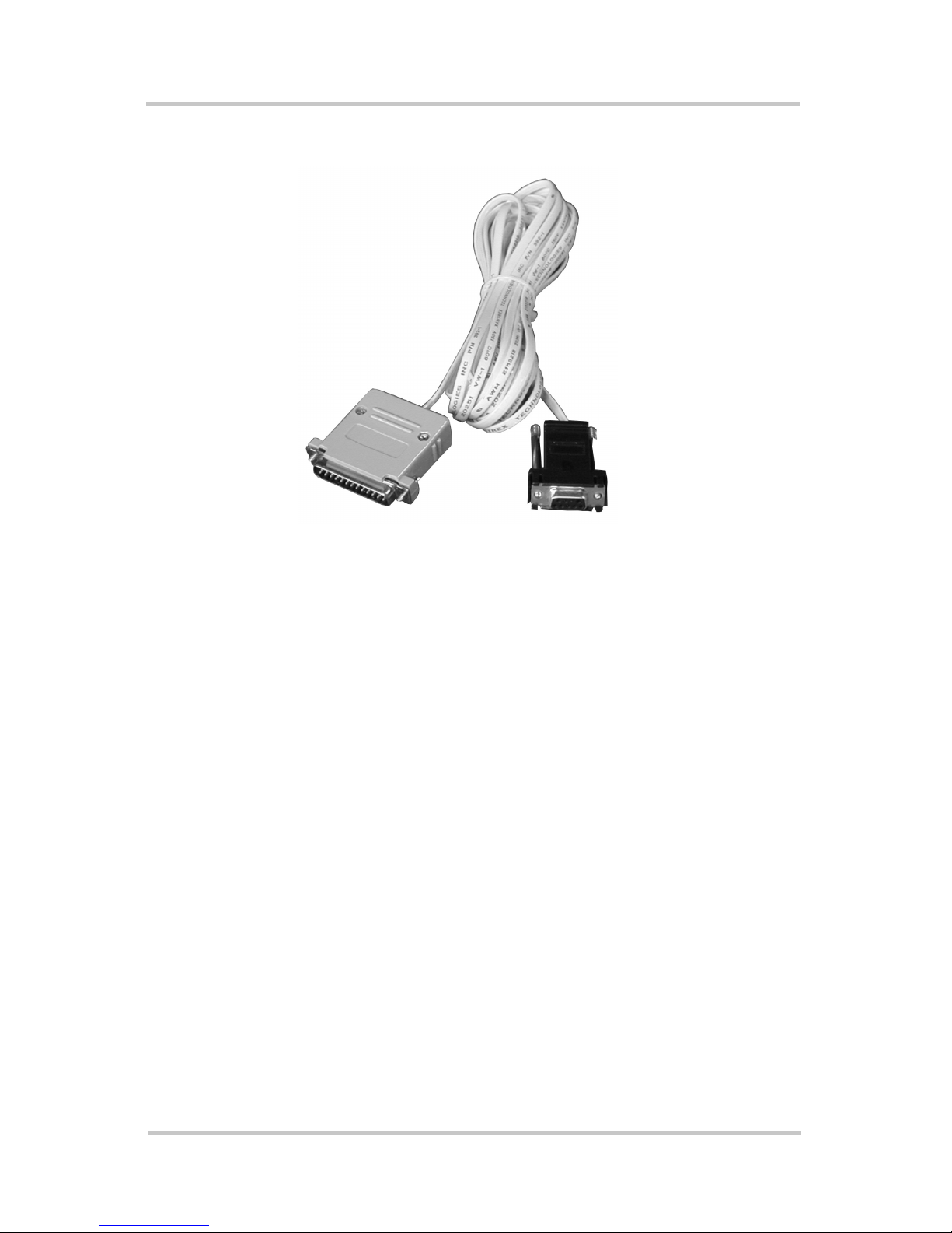
Features/Components
The ICA package includes the following items. See Figure 11 on page 3.
• ICA adapter: gray plastic housing with green LED, phone
(RJ11) jack and a 25-pin RS232 connector
• Serial Port Adapter: black plastic housing with RJ11 jack
and 9-pin connector. This part is custom-made. It is not
intended for use as a standard RJ11 to DB-9 adapter.
• 25-foot, 4-conductor phone cable, with RJ11 jacks on
each end (Telephone Standard)
• CD with the Windows™ based software program,
ICAP.exe, creating a simulation of the Sine Wave Plus
Inverter/Charger control panel
• This Inverter Communications Adapter (ICA) Owner’s
Manual
Please be sure all of these parts are included before trying to
use the ICA.
Features/Components
975-0052-01-01 Rev A 3
Figure 1-1
Inverter Communications Adapter (ICA)
ICA adapter
DB-9 Serial port
adapter
25’ phone cable

Installation
4 975-0052-01-01 Rev A
Connecting the ICA Cable
The ICA converts the REMOTE port on the Sine Wave Plus
Inverter/Charger into a standard RS232 type communications
port interface.
See Figure 1-2 for the location of the Remote Port on the Sine
Wave Plus Inverter/Charger.
To install the ICA:
1. Connect the ICA adapter to the Sine Wave Plus Inverter/
Charger remote port located on the left end of the
inverter, near the AC wiring compartment (Figure 1-2).
2. Connect the phone cable to the RJ11 jack on the gray
ICA adapter and to the black serial port adapter.
3. Plug the serial port adapter into the computer’s serial port
(Figure 1-2).
4. Check that the LED has illuminated to indicate that it can
communicate with the inverter.
Important:
There are two ports located on the inverter – one is
used for the stacking cable and the other is for the remote control
port. Make sure you connect the ICA to the correct port. If a
Remote Inverter Control Module (ICM-Remote) is being used, it
will have to be disconnected while the ICA is in use.
Important:
On some computers, a DB9-to-25-pin adapter may
be needed to allow connection.
Connecting the ICA Cable
975-0052-01-01 Rev A 5
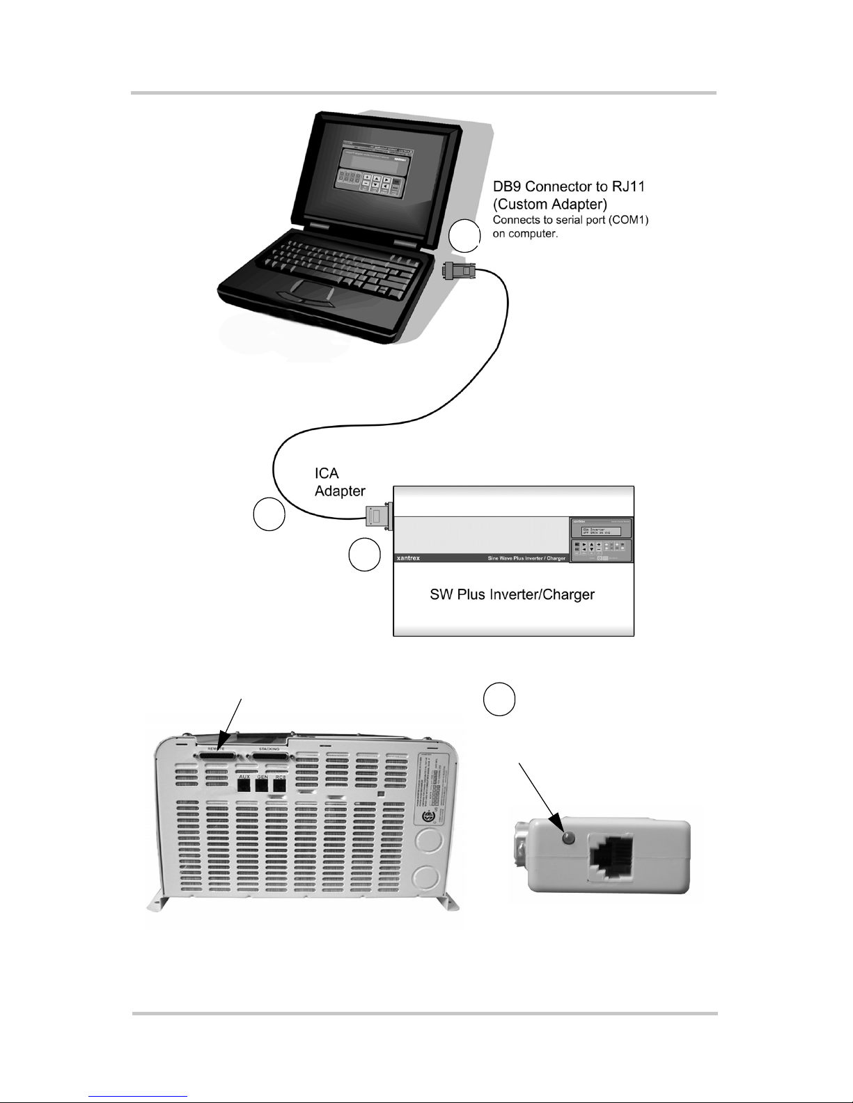
Figure 1-2
Connecting Directly to the Inverter
AC Side of Sine Wave Plus inverter
REMOTE Port
ICA Adapter
(LED and RJ11 port)
LED illuminates when the ICA
is able to communicate with
the inverter.
1
2
3
4
 Loading...