

Page 1
Erratum to GTI Owner’s Manual P/N 975-0041-01-02 Rev A
Section 2.0 INSTALLATION
The information in this erratum supersedes page 6 in the the GTI Owner’s
Manual, P/N 975-0041-01-02 Rev A.
Since the original release of this manual, mounting procedures for this unit
have changed to reflect design alterations that reduce potential noise issues.
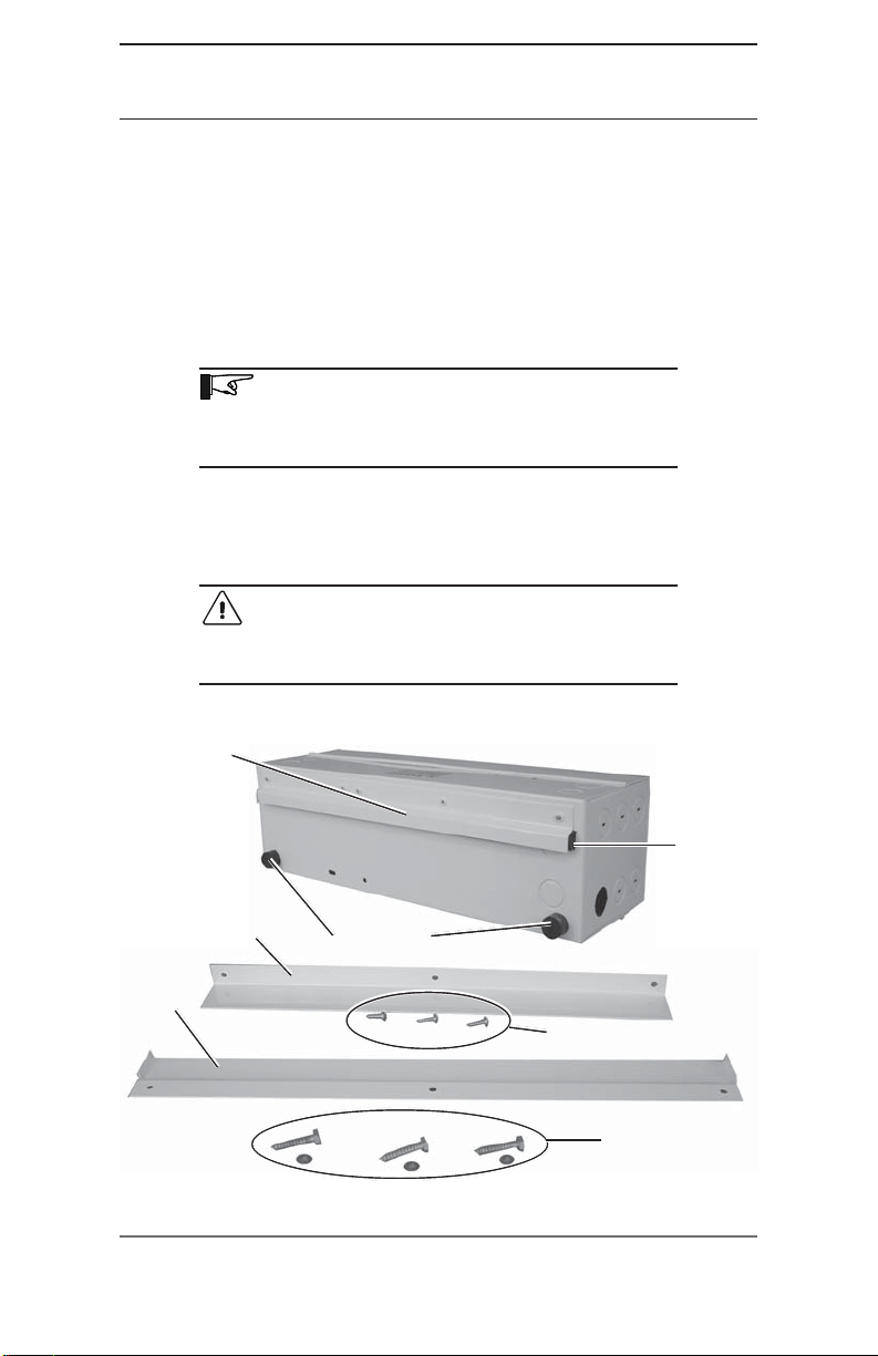
This unit now comes with a mounting bracket and stabilizing rubber feet attached
to the back of the unit, a mounting bracket for the wall, and one L-bracket for
above the unit to prevent it’s accidental dislocation.
MOUNTING
NOTE: Ensure that the GTI is close enough to the
inverter to connect the communications cable inside the
GTI. The cable extends approximately 2 feet out of the
inverter from behind the AC terminal block.
Place the GTI in a convenient location, close to the inverter. The GTI must
be mounted horizontally on a flat surface (such as a wall) in a clean, dry
environment. Do not mount the GTI where it will be exposed to the weather or in
a damp location.
CAUTION: The GTI weighs approximately 25
pounds. Use appropriate backing support material
(plywood, 2 x 4’s, etc.) and anchors that will support
its weight.
Mounting
Bracket
L-Bracket
Wall Bracket
©2002 Xantrex Technology Inc.
P/N 976-0038-01-01 Rev A 05/2002
Back of GTI Unit
Stabilizing Feet
Figure 2-2
Mounting Hardware
Rubber
Stripping
Mounting screws for L-Bracket
¼ x 1½" Hex-Head
lag screws and washers for
mounting Wall Bracket
1
Page 2
Erratum to GTI Owner’s Manual P/N 975-0041-01-02 Rev A
Section 2.0 INSTALLATION
NOTE: It may be easier to remove the appropriate
knockouts for the conduit(s) prior to mounting.
Procedure
1. Use a level and mark the location for the wall bracket on the wall in a
horizontal position.
2. Mark the 3 mounting screw holes.
3. If required, drill holes using a #10 (0.193" diameter) drill bit. Drill
appropriately sized holes for anchors when installing on non-wood
surfaces.
4. Mount the bracket to the wall using the three ¼ X 1½ hex-head lag screws
with the lip of the bracket facing the wall as shown in Figure 2-2a. If
mounting to other than a wood wall or surface, use appropriate screws and
anchors as required.
NOTE: The unit ships with the rubber stripping tucked
into the mounting bracket on the back of the unit. This
rubber stripping must prevent metal-to-metal contact
between the unit and the wall bracket.
If you have difficulty maintaining the integity of the
stripping while mounting the GTI into place, it might be
easier to remove this rubber stripping from the GTI unit
and apply it directly to the wall bracket.
5. Place the GTI’s mounting bracket located on the back of the GTI enclosure
over over
over
the wall bracket. Apply firm pressure to seat the mounting bracket on
over over
the enclosure securely over the wall bracket.
See Figure 2-2b.
6. Ensure the unit is correctly seated on the wall bracket.
See Figure 2-2c for examples of correct and incorrect placement of
the mounting bracket.
See Figure 2-2d for an example of a unit properly seated in the wall
bracket.
7. Mount the L-Bracket approximately 1/8 to 1/4 inch above the unit to
prevent the unit from accidentally dislocating from the wall bracket.
See Figure 2-2e.
CAUTION: The L-Bracket should not touch the GTI.
Otherwise, metal-to-metal contact may cause
excessive noise.
2
©2002 Xantrex Technology Inc.
P/N 976-0038-01-01 Rev A 05/2002
Page 3

Erratum to GTI Owner’s manual P/N 975-0041-01-02 Rev A
Section 2.0 INSTALLATION
¼ X 1½ Hex-head
lag screws and
washers
Figure 2-2a
Mount the Wall Bracket
Mounting
Bracket on
GTI
Rubber
Stripping
Wall
Bracket
Note the
position of
the lip
Figure 2-2b
Lift the GTI into place
INCORRECT
INCORRECT
CORRECT
Figure 2-2c
Ensure there is NO metal-to-metal contact between the GTI and the Wall Bracket
NOTE: The “lip” on the edge of the wall bracket has
been removed in Figure 2-2c to allow clearer visibility of
rubber strip placement for this example only.
©2002 Xantrex Technology Inc.
P/N 976-0038-01-01 Rev A 05/2002
3
Page 4

Erratum to GTI Owner’s Manual P/N 975-0041-01-02 Rev A
Section 2.0 INSTALLATION
Mounting
Bracket on
GTI
Rubber
Stripping
Wall
Bracket
The GTI properly placed on wall bracket
Figure 2-2d
Mounting screws
for L-Bracket
L-Bracket
Figure 2-2e
L-Bracket placed approximately 1/8 to 1/4 inch above the GTI
4
©2002 Xantrex Technology Inc.
P/N 976-0038-01-01 Rev A 05/2002
 Loading...