

Xantrex GT2.8-AU-QC-230, GT5.0-AU-QC-230 Owner's Manual
Xantrex Grid Tie
Solar Inverter
GT2.8-AU-QC-230
GT5.0-AU-QC-230
Owner’s Manual


Xantrex Grid Tie Solar Inverter
Owner’s Manual

About Xantrex
Xantrex Technology Inc. (www.xantrex.com), a subsidiary of Schneider Electric, is a world leader in the
development, manufacturing and marketing of advanced power electronic products and systems for the renewable
and mobile power markets. The company's products convert and control raw electrical power from any central,
distributed, renewable, or backup power source into high-quality power required by electronic equipment and the
electricity grid. Xantrex is headquartered in Vancouver, Canada, with facilities in the United States, Germany, Spain,
and a joint venture in China.
Trademarks
Xantrex and XPower are trademarks of Schneider Electric Services International sprl, registered in the U.S. and other
countries.
Other trademarks, registered trademarks, and product names are the property of their respective owners and are used
herein for identification purposes only.
Notice of Copyright
Copyright © April 2009 Xantrex Technology Inc. No part of this document may be reproduced in any form or
disclosed to third parties without the express written consent of:
Xantrex Technology Inc.
161-G South Vasco Road
Livermore, California
USA 94551
Xantrex Technology Inc. reserves the right to revise this document and to periodically make changes to the content
hereof without obligation or organization of such revisions or changes unless required to do so by prior arrangement.
Exclusion for Documentation
Unless specifically agreed to in writing, Xantrex Technology Inc. (“Xantrex”)
(
A) MAKES NO WARRANTY AS TO THE ACCURACY, SUFFICIENCY OR SUITABILITY OF ANY TECHNICAL OR OTHER
INFORMATION PROVIDED IN ITS MANUALS OR OTHER DOCUMENTATION.
(
B) ASSUMES NO RESPONSIBILITY OR LIABILITY FOR LOSSES, DAMAGES, COSTS OR EXPENSES, WHETHER SPECIAL,
DIRECT, INDIRECT, CONSEQUENTIAL OR INCIDENTAL, WHICH MIGHT ARISE OUT OF THE USE OF SUCH INFORMATION.
T
HE USE OF ANY SUCH INFORMATION WILL BE ENTIRELY AT THE USER’S RISK; AND
(C) REMINDS YOU THAT IF THIS MANUAL IS IN ANY LANGUAGE OTHER THAN ENGLISH, ALTHOUGH STEPS HAVE BEEN
TAKEN TO MAINTAIN THE ACCURACY OF THE TRANSLATION, THE ACCURACY CANNOT BE GUARANTEED. APPROVED
X
ANTREX CONTENT IS CONTAINED WITH THE ENGLISH LANGUAGE VERSION WHICH IS POSTED AT
WWW.XANTREX.COM.
Date and Revision
April 2009 Revision A
Document Part Number
975-0466-01-01
Product Part Numbers
864-1030 (GT2.8-AU-QC-230) and 864-1039 (GT5.0-AU-QC-230)
Contact Information
Telephone: 1 408 987 6030
Fax: 1 604 422 2756
Email: customerservice@xantrex.com
Web: www.xantrex.com

About This Manual
The purpose of this Owner’s Manual is to provide expl anations and procedures for
installing, operating, maintaining, and troubleshooting the Xantrex Grid T ie Solar
Inverter™.
Scope
The manual provides safety guidelin es, detailed planning and setup informatio n. It
provides procedures for installing the inverter and information about operating
and troubleshooting the unit. It does not provide details about particular brands of
photovoltaic (PV) panels. You need to consult individual PV manufacturers for
this information.
Audience
Chapter 1 and Chapter 5 are intended for anyone who needs to operate the
Xantrex Grid Tie Solar Inverter. Operators must be familiar with all the safety
regulations pertaining to operating high-voltage equipment as dictated by local
code. Operators must also have a complete understanding of this equipment’s
features and functions. Do not to use this product unless it has been installed by a
qualified installer in accordance with the instructions in Chapter 2, “Installation”.
Chapter 2, Chapter 3, Chapter 4, and Chapter 6 are intended for qualified
installers who need to install the Xantrex Grid Tie Solar Inverter. Qualified
installers have the training and experience in solar power systems to safely and
correctly follow these instructions and the applicable electrical and building
codes, in order to design and install a system that is safe and will operate correctly .
Qualified installers have an awareness of the hazards involved in performing
electrical installation work and how to reduce those hazards. Only qualified
personnel should perform the installation, commissioning and maintenance of the
GT Inverter.
Organization
This manual is organized into 6 chapters and an appendix.
Chapter 1, “Introduction”, contains information about the features and functions
of the Xantrex Grid Tie Solar Inverter.
Chapter 2, “Installation”, provides information about planning for and installing
the GT Inverter. It contains information to help you plan wire routes, ensure your
PV array provides necessary power, and find a suitable location for installation.
975-0466-01-01 iii
About This Manual
Chapter 3, “Wiring the Inverter”, provides procedures for making DC and AC
wiring connections for single and multiple inverter installations. This chapter also
includes information about communications wiring and using GT-View
monitoring software.
Chapter 4, “Starting the Inverter”, contains information on starting up the Xantrex
Grid Tie Solar Inverter and performing a functional test.
Chapter 5, “Monitoring the Inverter”, contains information for understanding the
LCD screens and the LED indicators.
Chapter 6, “Maintenance and Troubleshooting”, contains information about how to
provide general maintenance for the Xantrex Grid Tie Solar Inverter. It also
provides information about troubleshooting the unit.
Appendix A, “Specifications”, contains information about the electrical and
environmental specifications of the Xantrex Grid Tie Solar Inverter.
Conventions Used
The following conventions are used in this guide.
WARNING
Warnings identify conditions that could resul t in perso nal injury or loss of life.
CAUTION
Cautions identify conditions or practices that could result in damage to the unit or other
equipment.
Important:
serious as a caution or warning.
Abbreviations Used
GT Grid Tie
I
SC
LCD Liquid Crystal Display
LED Light Emitting Diode
MPPT Maximum Power Point Tracking
P
MAX
P
NOM
These notes describe things that are important for you to know, but not as
Short Circuit Current
Maximum Output Power
Nominal Output Power
iv 975-0466-01-01
PC Personal Computer
PV Photovoltaic
STC Standard Test Condition
Vac Volts AC
Vdc Volts DC
About This Manual
Symbols Used
V
MP
V
OC
U
PV
(
&
$
%
Voltage at Maximum Power
Open Circuit Voltage
PV Array DC Voltage
Alternating Current (AC)
Direct Current (DC)
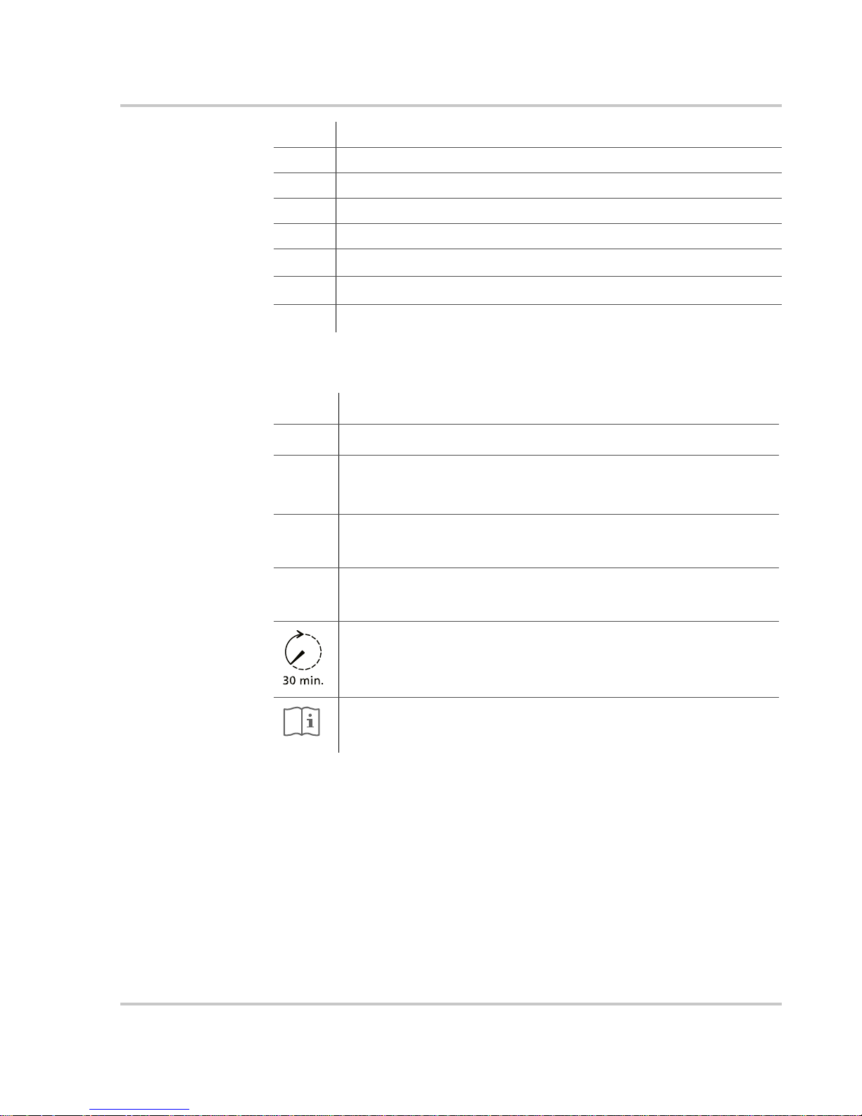
In this guide: Important information, warnings, or cautions.
On the product: Important information, warnings or cautions with furth e r
explanation in the product guide.
On the product: Warning, risk of electric shock.
On the product: Warning, Hot surface—risk of burns.
FOR AUTHORIZED SERVICE PERSONNEL: Before opening cover,
disconnect DC and AC power and wait 30 minutes to allow internal voltages
to reach safe levels.
NOTE: there are no user-serviceable parts inside.
Related Information
You can find more information about Xantrex Technology Inc. as well as its
products and services at www.xantrex.com
975-0466-01-01 v
Refer to the operating instructions.

vi
Important Safety Instructions
WARNING: Save these instructions
This manual contains important safety and operating instructions. Read and keep this
Owner’s Manual for future reference.
WARNING: Limitations on use
Do not use this GT Inverter in connection with life support systems, medical equipment,
or where human life or medical property may be at stake.
1. Before installing and using the GT Inverter, read all instructions and cautionary markings on the
inverter and in all appropriate sections of this guide.
2. To reduce shock, fire, and energy hazards the installation must be in accordance with all applicable
local installation codes. It is the installer’s responsibility to ensure adherence to applicable codes.
3. To reduce risk of fire hazard, do not cover or obstruct the heat sink.
4. Observe the clearance recommendations as described on page 2–12. Do not install the GT Inverter in a
zero-clearance or non-ventilated compartment. Overheating may result.
5. Use only accessories recommended or sold by the manufacturer. Doing otherwise may result in a risk
of fire, electric shock, or injury to persons.
6. T o avoid a risk of fire and electric shock, make sure that all wiring is in good condition and that wire is
not undersized. Do not operate the GT Inverter with damaged or substandard wiring.
7. Do not operate the GT Inverter if it has received a sharp blow, been dropped, or otherwise damaged in
any way. If the GT Inverter is damaged, see the Warranty section.
8. Do not disassemble the GT Inverter. It contains no user-serviceable parts. See Warranty for
instructions on obtaining service. Attempting to service the GT Inverter yourself may result in a risk of
electrical shock or fire and will void your warranty.
9. To reduce the risk of electrical shock, disconnect both AC and DC power from the GT Inverter before
attempting any maintenance or cleaning or working on any circuits connected to the inverter. Turning
off controls will not reduce this risk. Internal capacitors remain charged for up to 30 minutes after
disconnecting all sources of power.
10. The GT Inverter must be provided with an equipment-grounding conductor connected to the AC
ground.
975-0466-01-01 vii

Safety
Regulatory Compliance
The GT Inverter is compliant with the standards described below.
• Safety: Regulatory Compliance Mark (RCM) based on compliance with AS/NZS 3100 Approval and
test specification – General requirements for electrical equipment
• Electromagnetic Compatibility (EMC): RCM mark based on compliance with:
• EN61000-6-1 Generic standards – Immunity for residential, commercial, and light-industrial
environments
• EN61000-6-3 Generic standards – Emission standard for residential, commercial, and lightindustrial environments
• EN61000-3-2 Limits for harmonic current emissions
• EN61000-3-3 Limitations of voltage changes, voltage fluctuations, and flicker
• Interconnect: ResLab verified, compliant with the following:
• AS 4777.2-2005 Grid connection of energy systems via inverters – Inverter requir ements
• AS 4777.3-2005 Grid connection of energy systems via inverters – Grid protection requirements
The GT Inverter is designed for utility interactive operation. It has complete on-board over-current, overtemperature and anti-islanding protection. It monitors voltage and frequency of the utility grid and
automatically stops supplying power whenever conditions on the utility grid deviate from standard levels
(see Specifications).
The GT Inverter is equipped with a high frequency transformer that assures galvanic isolation between the
DC side and the utility power grid.
PV Ground Fault Detection
The GT Inverter is equipped with a ground fault detection circuit that measures the impedance to ground of
the array , before connecting to the grid. If a high impedance is not detected, it signals a fault and refuses to
connect. The GT Inverter will remain faulted until the ground fault is remedied and the inverter is
manually reset. See Table 6-1, “Troubleshooting the GT Inverter” on page 6–4.
viii 975-0466-01-01

Contents
Important Safety Instructions
Regulatory Compliance - - - - - - - - - - - - - - - - - - - - - - - - - - - - - - - - - - - - - - - - - - - - - - - - - - - viii
PV Ground Fault Detection - - - - - - - - - - - - - - - - - - - - - - - - - - - - - - - - - - - - - - - - - - - - - - - - viii
1
Introduction
About the Xantrex Grid Tie Solar Inverter- - - - - - - - - - - - - - - - - - - - - - - - - - - - - - - - - - - - - - 1–2
Standard Features - - - - - - - - - - - - - - - - - - - - - - - - - - - - - - - - - - - - - - - - - - - - - - - - - - - - - - 1–3
2
Installation
Installation Options - - - - - - - - - - - - - - - - - - - - - - - - - - - - - - - - - - - - - - - - - - - - - - - - - - - - - 2–2
Single Inverter Installation - - - - - - - - - - - - - - - - - - - - - - - - - - - - - - - - - - - - - - - - - - - - - - 2–2
Multiple Inverter Installations - - - - - - - - - - - - - - - - - - - - - - - - - - - - - - - - - - - - - - - - - - - 2–2
Planning the Installation - - - - - - - - - - - - - - - - - - - - - - - - - - - - - - - - - - - - - - - - - - - - - - - - - - 2–2
Inverter Location - - - - - - - - - - - - - - - - - - - - - - - - - - - - - - - - - - - - - - - - - - - - - - - - - - - - 2–4
PV Array Requirements - - - - - - - - - - - - - - - - - - - - - - - - - - - - - - - - - - - - - - - - - - - - - - - 2–5
Grounding Requirements - - - - - - - - - - - - - - - - - - - - - - - - - - - - - - - - - - - - - - - - - - - - - - - 2–7
Routing the Wires - - - - - - - - - - - - - - - - - - - - - - - - - - - - - - - - - - - - - - - - - - - - - - - - - - - 2–8
Preparing for the Installation - - - - - - - - - - - - - - - - - - - - - - - - - - - - - - - - - - - - - - - - - - - - - - - 2–8
Wiring - - - - - - - - - - - - - - - - - - - - - - - - - - - - - - - - - - - - - - - - - - - - - - - - - - - - - - - - - - - 2–8
AC Circuit Breaker Requirements - - - - - - - - - - - - - - - - - - - - - - - - - - - - - - - - - - - - - - - - - 2–9
AC and DC Disconnects - - - - - - - - - - - - - - - - - - - - - - - - - - - - - - - - - - - - - - - - - - - - - - -2–9
Mounting the Inverter - - - - - - - - - - - - - - - - - - - - - - - - - - - - - - - - - - - - - - - - - - - - - - - - - - - 2–9
Overview - - - - - - - - - - - - - - - - - - - - - - - - - - - - - - - - - - - - - - - - - - - - - - - - - - - - - - - - - 2–9
Tools and Materials Needed - - - - - - - - - - - - - - - - - - - - - - - - - - - - - - - - - - - - - - - - - - - - 2–10
Dimensions - - - - - - - - - - - - - - - - - - - - - - - - - - - - - - - - - - - - - - - - - - - - - - - - - - - - - - - 2–11
Installing the Mounting Bracket - - - - - - - - - - - - - - - - - - - - - - - - - - - - - - - - - - - - - - - - - 2–12
Mounting the Inverter on the Bracket - - - - - - - - - - - - - - - - - - - - - - - - - - - - - - - - - - - - - 2–16
- - - - - - - - - - - - - - - - - - - - - - - - - - - - - - - - - - - - - - - - - - -vii
3
Wiring the Inverter
Connecting the DC Wiring - - - - - - - - - - - - - - - - - - - - - - - - - - - - - - - - - - - - - - - - - - - - - - - - 3–2
Equipment Needed - - - - - - - - - - - - - - - - - - - - - - - - - - - - - - - - - - - - - - - - - - - - - - - - - - - 3–3
DC Fuses (GT5.0-AU Model Only for Three PV Strings) - - - - - - - - - - - - - - - - - - - - - - - - - 3–3
Connecting the PV Array - - - - - - - - - - - - - - - - - - - - - - - - - - - - - - - - - - - - - - - - - - - - - - 3–4
975-0466-01-01 ix

Contents
Connecting Multiple Inverters - - - - - - - - - - - - - - - - - - - - - - - - - - - - - - - - - - - - - - - - - - - - - 3–6
Connecting the AC Wiring- - - - - - - - - - - - - - - - - - - - - - - - - - - - - - - - - - - - - - - - - - - - - - - - 3–7
Making AC Connections for the GT2.8-AU Model - - - - - - - - - - - - - - - - - - - - - - - - - - - - - 3–7
Making AC Connections for GT5.0-AU Model - - - - - - - - - - - - - - - - - - - - - - - - - - - - - - - 3–9
Communications Wiring for Multiple Inverters- - - - - - - - - - - - - - - - - - - - - - - - - - - - - - - - - -3–10
Xanbus Network Technology - - - - - - - - - - - - - - - - - - - - - - - - - - - - - - - - - - - - - - - - - - -3–11
Guidelines for Routing the Network Cables - - - - - - - - - - - - - - - - - - - - - - - - - - - - - - - - - -3–13
Connecting Network Cable between Inverters - - - - - - - - - - - - - - - - - - - - - - - - - - - - - - - -3–14
Verifying the Xanbus Network - - - - - - - - - - - - - - - - - - - - - - - - - - - - - - - - - - - - - - - - - -3–15
Communications Wiring for Monitoring a Single Inverter- - - - - - - - - - - - - - - - - - - - - - - - - - -3–16
4
Starting the Inverter
Commissioning Procedure - - - - - - - - - - - - - - - - - - - - - - - - - - - - - - - - - - - - - - - - - - - - - - - - 4–2
Disconnect Test - - - - - - - - - - - - - - - - - - - - - - - - - - - - - - - - - - - - - - - - - - - - - - - - - - - - - - - 4–3
5
Monitoring the Inverter
Monitoring the Front Panel Display- - - - - - - - - - - - - - - - - - - - - - - - - - - - - - - - - - - - - - - - - - 5–2
Front Panel Display Screens and What They Mean - - - - - - - - - - - - - - - - - - - - - - - - - - - - - - - 5–3
Startup Mode - - - - - - - - - - - - - - - - - - - - - - - - - - - - - - - - - - - - - - - - - - - - - - - - - - - - - - 5–3
Normal Operation Mode - - - - - - - - - - - - - - - - - - - - - - - - - - - - - - - - - - - - - - - - - - - - - - 5–5
Offline Mode - - - - - - - - - - - - - - - - - - - - - - - - - - - - - - - - - - - - - - - - - - - - - - - - - - - - - - 5–7
Fault Mode - - - - - - - - - - - - - - - - - - - - - - - - - - - - - - - - - - - - - - - - - - - - - - - - - - - - - - - - 5–8
Special Screens - - - - - - - - - - - - - - - - - - - - - - - - - - - - - - - - - - - - - - - - - - - - - - - - - - - - -5–10
Custom Screens - - - - - - - - - - - - - - - - - - - - - - - - - - - - - - - - - - - - - - - - - - - - - - - - - - - -5–10
Status Indicator Lights- - - - - - - - - - - - - - - - - - - - - - - - - - - - - - - - - - - - - - - - - - - - - - - - - - -5–11
6
Maintenance and Troubleshooting
Factors Affecting GT Inverter Performance - - - - - - - - - - - - - - - - - - - - - - - - - - - - - - - - - - - - 6–2
PV Array Factors - - - - - - - - - - - - - - - - - - - - - - - - - - - - - - - - - - - - - - - - - - - - - - - - - - - 6–2
Other Factors - - - - - - - - - - - - - - - - - - - - - - - - - - - - - - - - - - - - - - - - - - - - - - - - - - - - - - 6–3
Performing General Maintenance - - - - - - - - - - - - - - - - - - - - - - - - - - - - - - - - - - - - - - - - - - - 6–3
Identifying Error/Fault Conditions and Solutions- - - - - - - - - - - - - - - - - - - - - - - - - - - - - - - - - 6–3
A
Specifications
Electrical Specifications - - - - - - - - - - - - - - - - - - - - - - - - - - - - - - - - - - - - - - - - - - - - - - - - - A–2
Input - - - - - - - - - - - - - - - - - - - - - - - - - - - - - - - - - - - - - - - - - - - - - - - - - - - - - - - - - - - - A–2
Output - - - - - - - - - - - - - - - - - - - - - - - - - - - - - - - - - - - - - - - - - - - - - - - - - - - - - - - - - - - A–2
Islanding Protection - - - - - - - - - - - - - - - - - - - - - - - - - - - - - - - - - - - - - - - - - - - - - - - - - - A–3
Adjustable Disconnect Settings - - - - - - - - - - - - - - - - - - - - - - - - - - - - - - - - - - - - - - - - - - A–3
Output Power Versus Ambient Temperature - - - - - - - - - - - - - - - - - - - - - - - - - - - - - - - - - A–4
Efficiency - - - - - - - - - - - - - - - - - - - - - - - - - - - - - - - - - - - - - - - - - - - - - - - - - - - - - - - - A–5
x 975-0466-01-01

Contents
Environmental Specifications - - - - - - - - - - - - - - - - - - - - - - - - - - - - - - - - - - - - - - - - - - - - - -A–5
User Display - - - - - - - - - - - - - - - - - - - - - - - - - - - - - - - - - - - - - - - - - - - - - - - - - - - - - - -A–5
Display Accuracy - - - - - - - - - - - - - - - - - - - - - - - - - - - - - - - - - - - - - - - - - - - - - - - - - - - -A–5
Mechanical Specifications - - - - - - - - - - - - - - - - - - - - - - - - - - - - - - - - - - - - - - - - - - - - - - - -A–5
Warranty and Return Information
Index
- - - - - - - - - - - - - - - - - - - - - - - - - - - - - - - - - - - - - - - - - - - - - - - - - - - - - - - - - - - - - - - - IX–1
- - - - - - - - - - - - - - - - - - - - - - - - - - - - - - - - - - - - WA–1
975-0466-01-01 xi

Contents
xii 975-0466-01-01

Figures
Figure 1-1 Basic System Overview - - - - - - - - - - - - - - - - - - - - - - - - - - - - - - - - - - - - - - - - - - - - 1–2
Figure 1-2 Main Features of the GT Inverter (GT2.8-AU Model Shown) - - - - - - - - - - - - - - - - - - 1–4
Figure 2-1 Installation Options Overview- - - - - - - - - - - - - - - - - - - - - - - - - - - - - - - - - - - - - - - - 2–3
Figure 2-2 GT Inverter mounting orientation - - - - - - - - - - - - - - - - - - - - - - - - - - - - - - - - - - - - - 2–5
Figure 2-3 Installation Overview- - - - - - - - - - - - - - - - - - - - - - - - - - - - - - - - - - - - - - - - - - - - - 2–10
Figure 2-4 GT Inverter Dimensions (GT5.0-AU shown)- - - - - - - - - - - - - - - - - - - - - - - - - - - - - 2–11
Figure 2-5 Mounting Bracket and GT Inverter - - - - - - - - - - - - - - - - - - - - - - - - - - - - - - - - - - - 2–12
Figure 2-6 Examples of Mounting on a Pole or Rails - - - - - - - - - - - - - - - - - - - - - - - - - - - - - - - 2–14
Figure 2-7 Installing the Mounting Bracket using Plywood Support - - - - - - - - - - - - - - - - - - - - - 2–15
Figure 2-8 Proper Placement of the Inverter on the Mounting Bracket - - - - - - - - - - - - - - - - - - - 2–16
Figure 3-1 PV Quick Connect Locations - - - - - - - - - - - - - - - - - - - - - - - - - - - - - - - - - - - - - - - - 3–2
Figure 3-2 GT5.0-AU DC Fuse Installation - - - - - - - - - - - - - - - - - - - - - - - - - - - - - - - - - - - - - - 3–4
Figure 3-3 DC Connections for a Two-String PV Array - - - - - - - - - - - - - - - - - - - - - - - - - - - - - - 3–5
Figure 3-4 Improper Multiple Inverter Connections - - - - - - - - - - - - - - - - - - - - - - - - - - - - - - - - - 3–6
Figure 3-5 AC Connector (Female) - - - - - - - - - - - - - - - - - - - - - - - - - - - - - - - - - - - - - - - - - - - - 3–8
Figure 3-6 AC Connector Terminals - - - - - - - - - - - - - - - - - - - - - - - - - - - - - - - - - - - - - - - - - - - 3–8
Figure 3-7 GT5.0-AU AC Wiring Compartment and Terminal Block - - - - - - - - - - - - - - - - - - - - - 3–9
Figure 3-8 Network Layout (Communication Ports Cover Not Installed)- - - - - - - - - - - - - - - - - - 3–11
Figure 3-9 Network Terminator - - - - - - - - - - - - - - - - - - - - - - - - - - - - - - - - - - - - - - - - - - - - - 3–12
Figure 3-10 Location of Xanbus RJ45 Ports - - - - - - - - - - - - - - - - - - - - - - - - - - - - - - - - - - - - - - 3–12
Figure 3-11 Network Cable - - - - - - - - - - - - - - - - - - - - - - - - - - - - - - - - - - - - - - - - - - - - - - - - - 3–13
Figure 3-12 Replacing the Communication Ports Cover - - - - - - - - - - - - - - - - - - - - - - - - - - - - - - 3–15
Figure 5-1 Front Panel LCD Location - - - - - - - - - - - - - - - - - - - - - - - - - - - - - - - - - - - - - - - - - - 5–2
Figure 5-2 Location of Status Indicator Lights - - - - - - - - - - - - - - - - - - - - - - - - - - - - - - - - - - - 5–11
Figure A-1 Output Power vs. Ambient Temperature (GT2.8-AU)- - - - - - - - - - - - - - - - - - - - - - - -A–4
Figure A-2 Output Power vs. Ambient Temperature (GT5.0-AU)- - - - - - - - - - - - - - - - - - - - - - - -A–4
975-0466-01-01 xiii

xiv

Tables
Table 2-1 MPPT Operational Window (GT2.8-AU) - - - - - - - - - - - - - - - - - - - - - - - - - - - - - - - - 2–6
Table 2-2 MPPT Operational Window (GT5.0-AU) - - - - - - - - - - - - - - - - - - - - - - - - - - - - - - - - 2–6
Table 2-3 Inverter Clearance Requirements- - - - - - - - - - - - - - - - - - - - - - - - - - - - - - - - - - - - - 2–12
Table 3-1 Recommended Fuses - - - - - - - - - - - - - - - - - - - - - - - - - - - - - - - - - - - - - - - - - - - - - - 3–3
Table 3-2 Total Xanbus Network Length - - - - - - - - - - - - - - - - - - - - - - - - - - - - - - - - - - - - - - 3–11
Table 3-3 Network Components and Part Numbers- - - - - - - - - - - - - - - - - - - - - - - - - - - - - - - - 3–13
Table 5-1 Startup Screens on GT5.0-AU Front Panel Display- - - - - - - - - - - - - - - - - - - - - - - - - - 5–3
Table 5-2 Normal Operation Default Screen - - - - - - - - - - - - - - - - - - - - - - - - - - - - - - - - - - - - - 5–5
Table 5-3 Normal Operation Screens for All GT Inverters - - - - - - - - - - - - - - - - - - - - - - - - - - - - 5–6
Table 5-4 Additional Normal Operation Screens for Each GT Inverter in a Multiple Unit System - 5–7
Table 5-5 Offline Mode Default Display- - - - - - - - - - - - - - - - - - - - - - - - - - - - - - - - - - - - - - - - 5–7
Table 5-6 Offline Mode Screens for All GT Inverters - - - - - - - - - - - - - - - - - - - - - - - - - - - - - - - 5–7
Table 5-7 Additional Offline Mode Screens for Each GT Inverter in a Multiple Unit System - - - - 5–8
Table 5-8 Fault Message Screens- - - - - - - - - - - - - - - - - - - - - - - - - - - - - - - - - - - - - - - - - - - - - 5–8
Table 5-9 Additional Fault Mode Screens - - - - - - - - - - - - - - - - - - - - - - - - - - - - - - - - - - - - - - - 5–9
Table 5-10 Special Message Screens - - - - - - - - - - - - - - - - - - - - - - - - - - - - - - - - - - - - - - - - - - 5–10
Table 5-11 Status Indicator LEDs - - - - - - - - - - - - - - - - - - - - - - - - - - - - - - - - - - - - - - - - - - - - 5–11
Table 6-1 Troubleshooting the GT Inverter - - - - - - - - - - - - - - - - - - - - - - - - - - - - - - - - - - - - - - 6–4
975-0466-01-01 xv

xvi

1
Introduction
Chapter 1, “Introduction”, contains information about the features
and functions of the Xantrex Grid Tie Solar Inverter.
The topics in this chapter are organized as follows:
• “About the Xantrex Grid Tie Solar Inverter” on page 1–2
• “Standard Features” on page 1–3
Introduction
About the Xantrex Grid Tie Solar Inverter
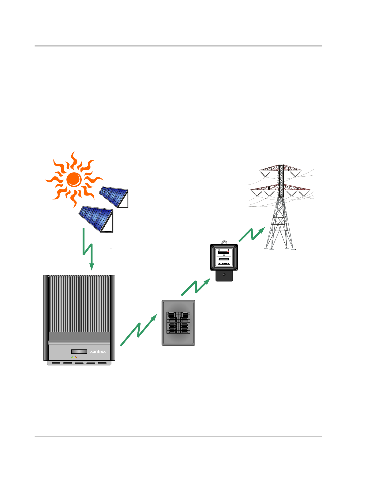
The Xantrex Grid Tie Solar Inverter (GT Inverter) is designed to convert solar
electric (photovoltaic or PV) power into utility-grade electricity that can be used
by the home or sold to the local power company.
Installing the GT Inverter consists of mounting it to the wall and connecting the
DC input to a PV array and the AC output to the utility. See Figure 1-1 for a
simple diagram of a typical installation.
In order to operate, the GT Inverter must have grid power available and
connected. It will not provide backup power if the AC grid fails.
Photovoltaic (PV) Panels—
PV Array
Harvested solar energy
DC converted to AC
Grid Tie Solar Inverter
GT Inverter
Figure 1-1 Basic System Overview
Main Utility
Service Panel
Power routed to utility grid
kWh
00000008
230V 50 Hz10(60)A
Utility Meter
Utility Grid
1–2 975-0466-01-01

Standard Features
PV compatibility The GT Inverter is designed to take advantage of solar modules configured as
high voltage PV string arrays—single crystalline, poly crystalline, or thin film—
with a 195 to 550 Vdc output voltage Maximum Power Point range (240 to 550
Vdc for the GT5.0-AU model).
Maximum Power
Point Tracking
(MPPT)
The GT Inverter uses Xantrex proprietary Maximum Power Point Tracking
(MPPT) technology to harvest the maximum amount of energy from the solar
array. MPPT learns your array’s specific characteristics, maximizing its output at
all times.
High efficiency The high-frequency, solid-state design of the GT Inverter is extremely efficient—
up to 96%.
Expandable Multiple GT Inverters may be networked together for increased net metering
capacity or future system growth.
Communications
protocol
The GT Inverter uses the Xanbus
communicate with multiple units connected within the system. For more
®
communications protocol, enabling it to
information, see “Xanbus Network Technology” on page 3–11.
Standard Features
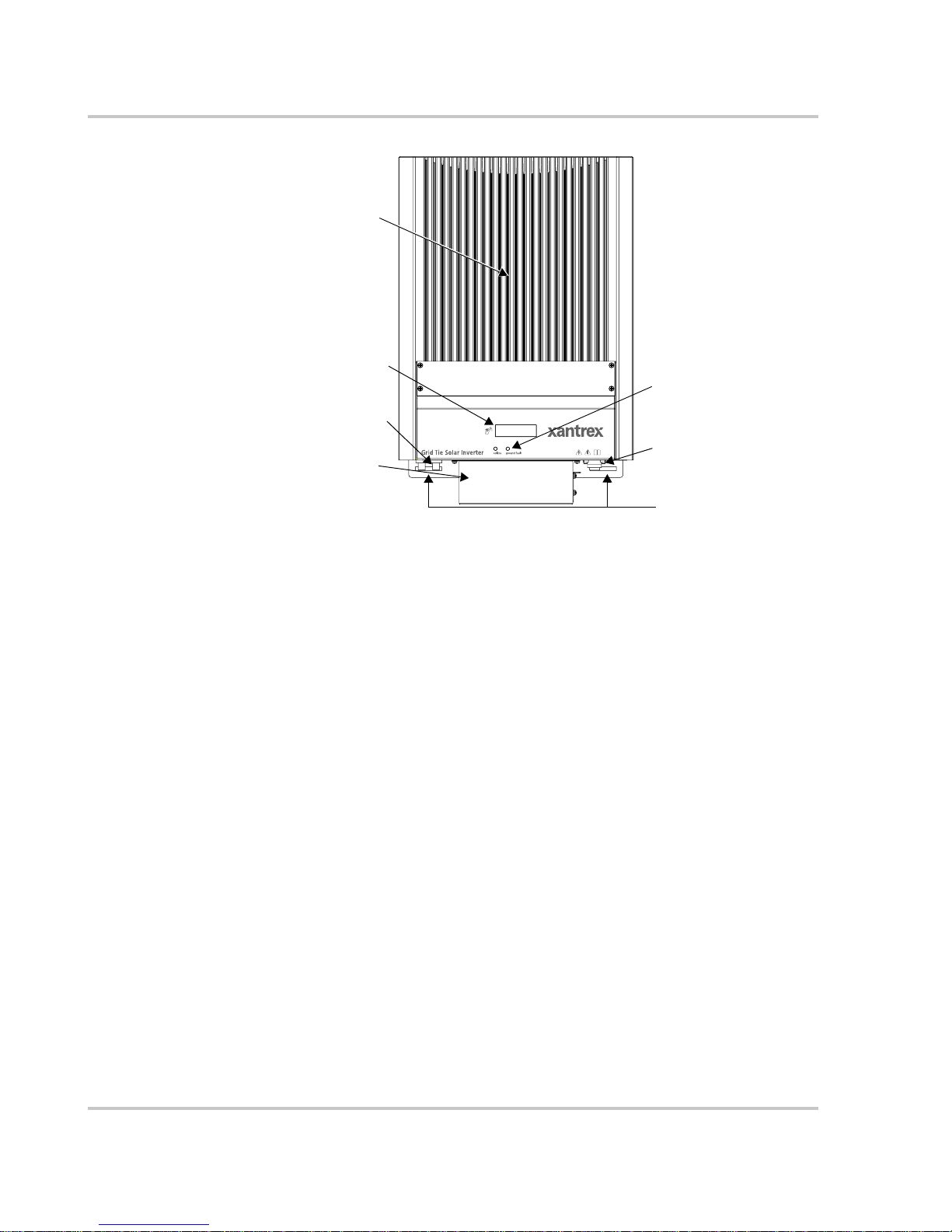
The GT Inverter has the following standard features:
• Sealed inverter (IP54) with external heat sink to protect power electronic
components
• Quick-connect connections for DC input (both models) and for AC output
(GT2.8-AU model only)
• Liquid Crystal Display (LCD) to provide easy-to-read system status and daily
cumulative energy production information
• Two LED indicator lights to provide status and ground fault indication.
975-0466-01-01 1–3
Introduction
Heat sink
LCD
LED indicator lights
DC quick-connects
Communication
ports cover
Figure 1-2
AC connection
Mounting slots (five)
Main Features of the GT Inverter (GT2.8-AU Model Shown)
1–4 975-0466-01-01

2
Installation
Chapter 2, “Installation”, provides information about planning for and
installing the GT Inverter. It contains information to help you plan
wire routes, ensure your PV array provides necessary power, and find
a suitable location for installation.
The topics in this chapter are organized as follows:
• “Installation Options” on page 2–2
• “Planning the Installation” on page 2–2
• “Preparing for the Installation” on page 2–8
• “Mounting the Inverter” on page 2–9.

Installation
Installation Options
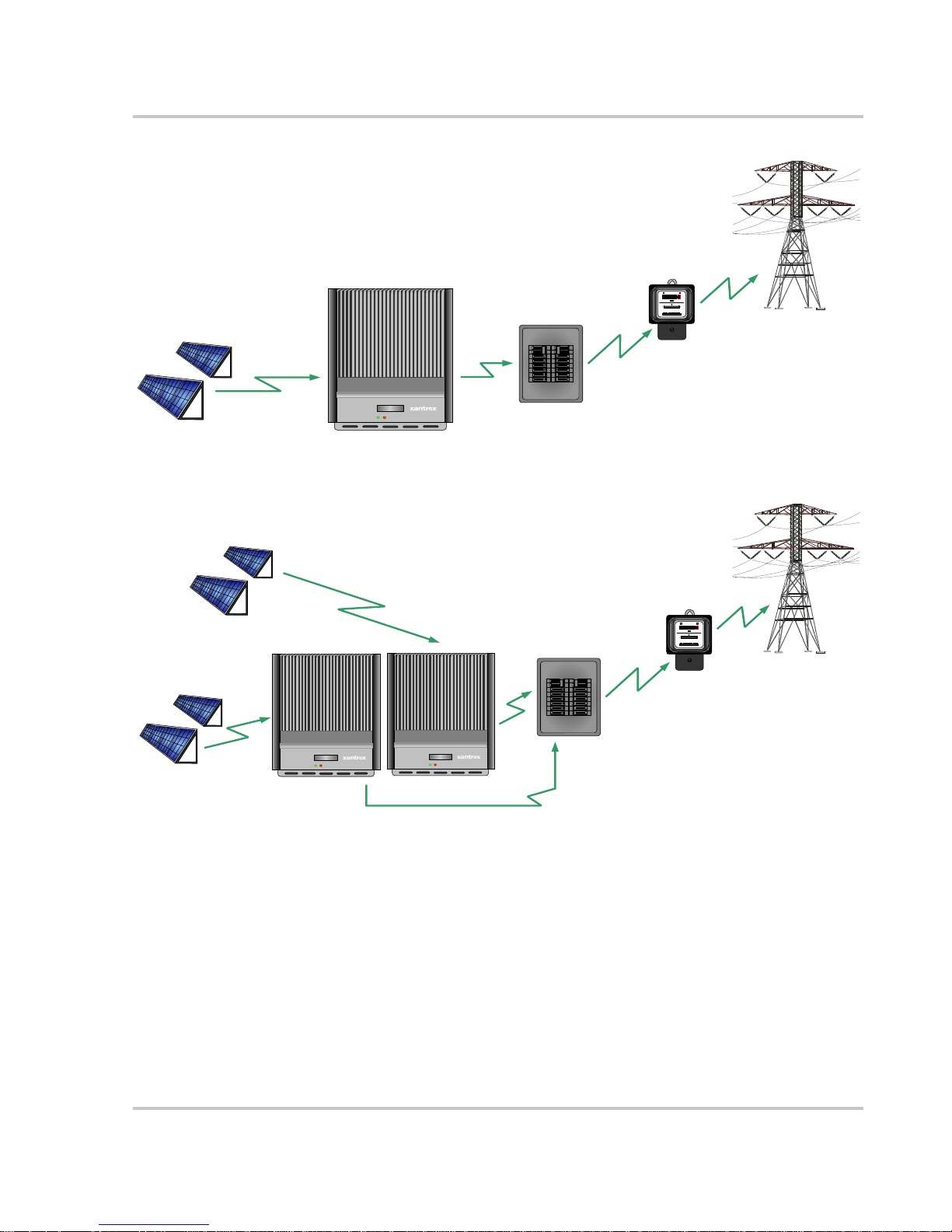
The GT Inverter may be installed as a single inverter for a single PV array of up to
two PV strings (up to three PV strings for the GT5.0-AU model), or in a multiple
inverter configuration for multiple PV arrays (see Figure 2-1 for diagrams of both
options).
Single Inverter Installation
In this configuration, a single inverter collects the harvested solar energy and
routes the power to the main utility service panel and the utility grid.
Multiple Inverter Installations
If multiple inverters are used, each inverter must be wired to an independent PV
array . In this configuration, each inverter collects the harvested solar energy from
a separate PV array and routes the power to the main utility service panel and the
utility grid.
Communications between inverters is optional, but can be enabled by installing
communications cabling to the inverter RJ45 ports. See “Connecting Network
Cable between Inverters” on page 3–14.
Planning the Installation
The following issues need to be considered when planning for an installation
using the GT Inverter. See the specified sections for more information.
• “Inverter Location” on page 2– 4
• “PV Array Requirements” on page 2–5
• “Grounding Requirements” on page 2–7
• “Routing the Wires” on page 2–8.
Ensure that you have obtained all permits required by local authorities or utilities
before commencing installation.
2–2 975-0466-01-01
Single Inverter Installation
DC converted to AC
Planning the Installation
Surplus power routed
to utility grid
0000
kW
h
0008
50 Hz10(60)
230V
A
Utility Meter
Utility Grid
Harvested solar energy
Photovoltaic (PV) Panels—
PV Array
PV Array #2
Photovoltaic Panels—
Multiple PV Arrays
Harvested
solar energy
Grid T ie
Solar
Inverter
GT Inverter #1 GT Inverter #2
PV Array #1
Grid Tie Solar
Inverter
GT Inverter
Main Utility
Service Panel
Multiple Inverter Installation
Harvested solar energy
DC converted to AC
Grid T ie
Solar
Inverter
DC converted to AC
Main Utility
Service Panel
Surplus power routed
to Utility Grid
0000
kW
h
0008
50 Hz10(60)
230V
A
Utility Meter
Utility Grid
Figure 2-1
Installation Options Overview
975-0466-01-01 2–3

Installation
Inverter Location
WARNING: Burn hazard
Do not install in normal traffic areas or other locations where people can accidentally
come into contact with the front of the inverter. High temperatures can be present on the
face of the inverter that can cause skin burns if accidentally touched..
Inverter failure due to improper installation will void the inverter warranty.
Consider the following when determining where to install the inverter.
Fire Safety
Indoor/
Outdoor
Orientation
Temperature
Ground
Clearance
Distance
• Do not install anywhere near combustible or flammable materials such
as stored fuels and solvents.
• The GT Inverter can be mounted indoors or outdoors.
• In outdoor installations the GT Inverter is rated for exposure to rain
and snow, but it should be located away from lawn sprinklers and
other sources of spray.
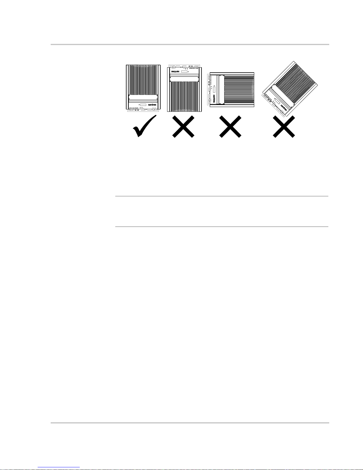
• The GT Inverter must be mounted vertically (with DC and AC
connectors facing down) on a wall or pole. See Figure 2-2.
• Ensure that the GT Inverter is mounted in a location where the
ambient temperature range is -25 to 65 °C.
• At extreme cold temperatures, the front panel LCD may not function
normally. At higher temperatures, the unit may derate power. See
“Environmental Specifications” on page A–5 and “Output Power vs.
Ambient Temperature (GT2.8-AU)” on page A–4.
• Outdoors, the GT Inverter requires at least 100 cm of clearance
between the bottom of the unit and the ground. This clearance helps
prevent water from splashing onto the bottom of the unit.
• Install the GT Inverter at a height at which the LCD is easily readable.
• T o minimize power losses in wiring, ensure that wire lengths between
the PV array and the GT Inverter and between the inverter and the
Main Utility Service Panel are kept to a minimum.
• Maximum distances will depend on wire gauges used and PV array
output voltages. To minimize system failures due to AC voltage
faults, Xantrex recommends sizing the AC and DC wiring to have a
maximum 1 to 1.5% voltage drop.
Debris free
2–4 975-0466-01-01
• Excessive debris (such as dust, leaves, and cobwebs) can accumulate
on the unit, interfering with wiring connections and ventilation. Do
not install in a location where debris can accumulate (such as under a
tree).
Planning the Installation
Figure 2-2
GT Inverter mounting orientation
PV Array Requirements
Equipment and Installation Recommendations
Equipment
recommendations
Installation
recommendations
Important:
small obstructions such as antennas, chimneys, and power lines. As well, be aware of
potential obstructions from growing trees and neighboring buildings. A small amount of
shade can have a disproportionately high impact on system performance.
• All electrical equipment should be approved for the voltage and current
ratings necessary for the application.
• All wiring should be sized correctly to minimize voltage drop.
• All exposed wires or conduits should be sunlight resistant.
• All required overcurrent protection and disconnecting means should be
included in the system and accessible for maintenance.
• All electrical terminations should be fully tightened, secured, and strain
relieved as appropriate.
• All mounting equipment should be installed according to the manufacturer’s
specifications.
• All wires, conduit, exposed conductors and electrical boxes should be secured
and supported according to code requirements.
The PV array should be free of shade. This requirement includes even
MPPT Requirements
MPPT operational
window
975-0466-01-01 2–5
The MPPT software maximizes the output energy of solar arrays as long as the
operating voltage is within the MPPT operational window. Ensure that the PV
array used in the system operates within the MPPT operational window.
Effects of array voltages outside of the MPPT operational window are shown in
Table 2-1.
 Loading...