

Page 1
Xantrex Grid Tie
Solar Inverter
GT 2.5-DE
GT 3.8-DE
GT 2.8-SP
GT 3.8-SP
GT 5.0-SP
Owner’s Manual
Page 2

Page 3

Xantrex Grid Tie Solar Inverter
Owner’s Manual
Page 4

About Xantrex
Xantrex Technology Inc. is a world-leading supplier of advanced power electronics and controls with products
ranging from small mobile units to utility-scale systems for wind, solar, batteries, fuel cells, microturbines, and
backup power applications in both grid-connected and stand-alone systems. Xantrex products include inverters,
battery chargers, programmable power supplies, and variable speed drives that convert, supply, control, clean, and
distribute electrical power.
Trademarks
Xantrex Grid Tie Solar Inverter is a trademark of Xantrex International. Xantrex and Xanbus are registered
trademarks of Xantrex International.
Other trademarks, registered trademarks, and product names are the property of their respective owners and are used
herein for identification purposes only.
Notice of Copyright
Xantrex Grid Tie Solar Inverter Owner’s Manual © September 2007 Xantrex International. All rights reserved.
Disclaimer
UNLESS SPECIFICALLY AGREED TO IN WRITING, XANTREX TECHNOLOGY INC. (“XANTREX”)
(a) MAKES NO WARRANTY AS TO THE ACCURACY, SUFFICIENCY OR SUITABILITY OF ANY
TECHNICAL OR OTHER INFORMATION PROVIDED IN ITS MANUALS OR OTHER DOCUMENTATION.
(b) ASSUMES NO RESPONSIBILITY OR LIABILITY FOR LOSS OR DAMAGE, WHETHER DIRECT,
INDIRECT, CONSEQUENTIAL OR INCIDENTAL, WHICH MIGHT ARISE OUT OF THE USE OF SUCH
INFORMATION. THE USE OF ANY SUCH INFORMATION WILL BE ENTIRELY AT THE USER’S RISK.
Date and Revision
September 2007 Revision C
Part Number
975-0253-01-01
Product Numbers
864-0105 (GT2.8-SP-QC-230), 864-0104 (GT3.8-SP-QC-230), 864-1029 (GT5.0-SP-QC-230), 864-0106 (GT2.5DE-QC-230), 864-0103 (GT3.8-DE-QC-230)
Contact Information
Telephone: +34 93 470 5330
Fax: +34 93 473 6093
Email: support.europe@xantrex.com
Web: www.xantrex.com
Page 5

About This Manual
The purpose of this Owner’s Manual is to provide expl anations and procedures for
installing, operating, maintaining, and troubleshooting the Xantrex Grid T ie Solar
Inverter™.
Scope
The manual provides safety guidelin es, detailed planning and setup informatio n. It
provides procedures for installing the inverter and information about operating
and troubleshooting the unit. It does not provide details about particular brands of
photovoltaic (PV) panels. You need to consult individual PV manufacturers for
this information.
Audience
The manual is intended for anyone who needs to install and operate the GT
Inverter. Installers should be fully educated on the hazards of installing electrical
equipment. Certified electricians or technicians are recommended.
Organization
This manual is organized into 6 chapters and an appendix.
Chapter 1, “Introduction”, contains information about the features and functions
of the Xantrex Grid Tie Solar Inverter.
Chapter 2, “Installation”, provides information about planning for and installing
the GT Inverter. It contains information to help you plan wire routes, ensure your
PV array provides necessary power, and find a suitable location for installation.
Chapter 3, “Wiring the Inverter”, provides procedures for making DC and AC
wiring connections for single and multiple inverter installations. This chapter also
includes information about communications wiring and using GT-V iew
monitoring software.
Chapter 4, “Starting the Inverter”, contains information on starting up the Xantrex
Grid Tie Solar Inverter and performing a functional test.
Chapter 5, “Monitoring the Inverter”, contains information for understanding the
LCD screens and the LED indicators.
Chapter 6, “Maintenance and Troubleshooting”, contains information about how to
provide general maintenance for the Xantrex Grid Tie Solar Inverter. It also
provides information about troubleshooting the unit.
Appendix A, “Specifications”, contains information about the electrical and
environmental specifications of the Xantrex Grid Tie Solar Inverter.
975-0253-01-01 iii
Page 6
About This Manual
Conventions Used
The following conventions are used in this guide.
WARNING
Warnings identify conditions that could resul t in perso nal injury or loss of life.
CAUTION
Cautions identify conditions or practices that could result in damage to the unit or other
equipment.
Important:
serious as a caution or warning.
Abbreviations Used
GT Grid Tie
I
SC
LCD Liquid Crystal Display
LED Light Emitting Diode
MPPT Maximum Power Point Tracking
P
MAX
P
NOM
PC Personal Computer
PV Photovoltaic
STC Standard Test Condition
Vac Volts AC
Vdc Volts DC
V
MP
These notes describe things that are important for you to know, but not as
Short Circuit Current
Maximum Output Power
Nominal Output Power
Voltage at Maximum Power
V
OC
U
PV
iv 975-0253-01-01
Open Circuit Voltage
PV Array DC Voltage
Page 7
Symbols Used
About This Manual
Related Information
Alternating Current (AC)
Direct Current (DC)
In this guide: Important information, warnings, or cautions.
On the product: Important information, warnings or cautions with furth e r
explanation in the product guide.
Caution, risk of electric shock.
Hot surface—risk of burns.
FOR AUTHORIZED SERVICE PERSONNEL: Before opening cover,
disconnect DC and AC power and wait 30 minutes to allow internal voltages
to reach safe levels.
NOTE: there are no user-serviceable parts inside.
Refer to the operating instructions.
You can find more information about Xantrex Technology Inc. as well as its
products and services at www.xantrex.com
975-0253-01-01 v
Page 8

vi
Page 9

Important Safety Instructions
SAVE THESE INSTRUCTIONS—This manual contains important instructions that shall be followed
during the installation and maintenance of the Xantrex Grid Tie Solar Inverter.
1. Before installing and using the GT Inverter, read all instructions and cautionary markings on the
inverter and in all appropriate sections of this guide.
2. To reduce risk of fire hazard, do not cover or obstruct the heat sink.
3. Observe the clearance recommendations as described on page 2–12. Do not install the G T In verter in a
zero-clearance or non-ventilated compartment. Overheating may result.
4. Use only accessories recommended or sold by the manufacturer. Doing otherwise may result in a risk
of fire, electric shock, or injury to persons.
5. To avoid a risk of fire and electric shock, make sure that existing wiring is in good condition and that
wire is not undersized. Do not operate the GT Inverter with damaged or substandard wiring.
6. Do not operate the G T Inverter if it has received a sharp blow, been dropped, or otherwise damaged in
any way. If the GT Inverter is damaged, see the Warranty section.
7. Do not disassemble the G T Inverter. It contains no user -serviceable parts. See Warranty for instructions
on obtaining service. Attempting to service the GT Inverter yourself may result in a risk of electrical
shock or fire and will void the factory warranty.
8. To reduce the risk of electrical shock, disconnect both AC and DC power from the GT Inverter before
attempting any maintenance or cleaning or working on any circuits connected to the inverter. Turning
off controls will not reduce this risk. Internal capacitors remain charged for up to 30 minutes after
disconnecting all sources of power.
9. The GT Inverter must be provided with an equipment-grounding conductor connected to the AC
ground.
975-0253-01-01 vii
Page 10

Safety
Regulatory Compliance
The GT Inverter is CE Marked for the following Directives and standards:
• Low Voltage Directive 73/23/EEC, per EN50178 “Electronic Equipment for Use in Power
Installations”.
• EMC Directive 204/108/EC, per:
• EN61000-6-3 “Emission Standard for Residential, Commercial, and Light-Industrial
Environments”
• EN61000-6-1 “Immunity for Residential, Commercial, and Light-Industrial Environments”
• EN61000-3-2 “Limits for Harmonic Current Emissions”
• EN61000-3-3 “Limitations of Voltage Fluctuations and Flicker”.
The GT Inverter is designed for utility interactive operation. It has complete on-board over-current, overtemperature and anti-islanding protection. It monitors voltage and frequency of the utility grid and
automatically stops supplying power whenever conditions on the utility grid deviate from standard levels
(see Specifications).
The GT Inverter is equipped with a high frequency transformer that assures galvanic isolation between the
DC side and the utility power grid.
German models have an integrated ENS and comply with the VDE 0126 regulations for supplementary
grid connection, especially to the “regulation for the supplementary grid feeding with photovoltaic
electricity producing facilities to the low voltage power supply grid” issued by the VDEW.
Spanish models comply with Royal Decree 1663/2000 and with section 10 of Annex XI of Royal Decree
661/2007, regarding the connection of photovoltaic installations to the low tension network.
viii 975-0253-01-01
Page 11

Contents
Important Safety Instructions
Regulatory Compliance - - - - - - - - - - - - - - - - - - - - - - - - - - - - - - - - - - - - - - - - - - - - - - - - - - viii
1
Introduction
About the Xantrex Grid Tie Solar Inverter- - - - - - - - - - - - - - - - - - - - - - - - - - - - - - - - - - - - - - 1–2
Standard Features - - - - - - - - - - - - - - - - - - - - - - - - - - - - - - - - - - - - - - - - - - - - - - - - - - - - 1–3
2
Installation
Installation Options - - - - - - - - - - - - - - - - - - - - - - - - - - - - - - - - - - - - - - - - - - - - - - - - - - - - - 2–2
Single Inverter Installation - - - - - - - - - - - - - - - - - - - - - - - - - - - - - - - - - - - - - - - - - - - - - - 2–2
Multiple Inverter Installations - - - - - - - - - - - - - - - - - - - - - - - - - - - - - - - - - - - - - - - - - - - 2–2
Planning the Installation - - - - - - - - - - - - - - - - - - - - - - - - - - - - - - - - - - - - - - - - - - - - - - - - - - 2–2
Inverter Location - - - - - - - - - - - - - - - - - - - - - - - - - - - - - - - - - - - - - - - - - - - - - - - - - - - - 2–4
PV Array Requirements - - - - - - - - - - - - - - - - - - - - - - - - - - - - - - - - - - - - - - - - - - - - - - - 2–5
Grounding Requirements - - - - - - - - - - - - - - - - - - - - - - - - - - - - - - - - - - - - - - - - - - - - - - - 2–7
Routing the Wires - - - - - - - - - - - - - - - - - - - - - - - - - - - - - - - - - - - - - - - - - - - - - - - - - - - 2–8
Preparing for the Installation - - - - - - - - - - - - - - - - - - - - - - - - - - - - - - - - - - - - - - - - - - - - - - - 2–9
Wiring - - - - - - - - - - - - - - - - - - - - - - - - - - - - - - - - - - - - - - - - - - - - - - - - - - - - - - - - - - - 2–9
AC Circuit Breaker Requirements - - - - - - - - - - - - - - - - - - - - - - - - - - - - - - - - - - - - - - - - - 2–9
AC and DC Disconnects - - - - - - - - - - - - - - - - - - - - - - - - - - - - - - - - - - - - - - - - - - - - - - - 2–9
Mounting the Inverter - - - - - - - - - - - - - - - - - - - - - - - - - - - - - - - - - - - - - - - - - - - - - - - - - - 2–10
Overview - - - - - - - - - - - - - - - - - - - - - - - - - - - - - - - - - - - - - - - - - - - - - - - - - - - - - - - - 2–10
Tools and Materials Needed - - - - - - - - - - - - - - - - - - - - - - - - - - - - - - - - - - - - - - - - - - - - 2–11
Dimensions - - - - - - - - - - - - - - - - - - - - - - - - - - - - - - - - - - - - - - - - - - - - - - - - - - - - - - - 2–11
Installing the Mounting Bracket - - - - - - - - - - - - - - - - - - - - - - - - - - - - - - - - - - - - - - - - - 2–12
Mounting the Inverter on the Bracket - - - - - - - - - - - - - - - - - - - - - - - - - - - - - - - - - - - - - 2–16
- - - - - - - - - - - - - - - - - - - - - - - - - - - - - - - - - - - - - - - - - - -vii
3
Wiring the Inverter
Connecting the DC Wiring - - - - - - - - - - - - - - - - - - - - - - - - - - - - - - - - - - - - - - - - - - - - - - - - 3–2
Equipment Needed - - - - - - - - - - - - - - - - - - - - - - - - - - - - - - - - - - - - - - - - - - - - - - - - - - - 3–3
DC Fuses (GT5.0-SP Model Only) - - - - - - - - - - - - - - - - - - - - - - - - - - - - - - - - - - - - - - - - 3–3
Connecting the PV Array - - - - - - - - - - - - - - - - - - - - - - - - - - - - - - - - - - - - - - - - - - - - - - 3–4
Connecting Multiple Inverters - - - - - - - - - - - - - - - - - - - - - - - - - - - - - - - - - - - - - - - - - - - - - - 3–6
Connecting the AC Wiring - - - - - - - - - - - - - - - - - - - - - - - - - - - - - - - - - - - - - - - - - - - - - - - - 3–7
Making AC Connections for GT2.5-DE, GT3.8-DE, GT2.8-SP, GT3.8-SP Models - - - - - - - 3–7
Making AC Connections for GT5.0-SP Model - - - - - - - - - - - - - - - - - - - - - - - - - - - - - - - - 3–9
Communications Wiring for Multiple Inverters - - - - - - - - - - - - - - - - - - - - - - - - - - - - - - - - - 3–10
975-0253-01-01 ix
Page 12

Contents
Xanbus Network Technology - - - - - - - - - - - - - - - - - - - - - - - - - - - - - - - - - - - - - - - - - - -3–10
Guidelines for Routing the Network Cables - - - - - - - - - - - - - - - - - - - - - - - - - - - - - - - - - -3–12
Connecting Network Cable between Inverters - - - - - - - - - - - - - - - - - - - - - - - - - - - - - - - -3–13
Communications Wiring for Monitoring a Single Inverter - - - - - - - - - - - - - - - - - - - - - - - -3–14
4
Starting the Inverter
Commissioning Procedure - - - - - - - - - - - - - - - - - - - - - - - - - - - - - - - - - - - - - - - - - - - - - - - - 4–2
Disconnect Test - - - - - - - - - - - - - - - - - - - - - - - - - - - - - - - - - - - - - - - - - - - - - - - - - - - - - - - 4–3
5
Monitoring the Inverter
Monitoring the Front Panel Display- - - - - - - - - - - - - - - - - - - - - - - - - - - - - - - - - - - - - - - - - - 5–2
Front Panel Display Screens and What They Mean - - - - - - - - - - - - - - - - - - - - - - - - - - - - - - - 5–3
Startup Mode - - - - - - - - - - - - - - - - - - - - - - - - - - - - - - - - - - - - - - - - - - - - - - - - - - - - - - 5–3
Normal Operation Mode - - - - - - - - - - - - - - - - - - - - - - - - - - - - - - - - - - - - - - - - - - - - - - 5–5
Offline Mode - - - - - - - - - - - - - - - - - - - - - - - - - - - - - - - - - - - - - - - - - - - - - - - - - - - - - - 5–7
Fault Mode - - - - - - - - - - - - - - - - - - - - - - - - - - - - - - - - - - - - - - - - - - - - - - - - - - - - - - - - 5–9
Special Screens - - - - - - - - - - - - - - - - - - - - - - - - - - - - - - - - - - - - - - - - - - - - - - - - - - - - -5–11
Custom Screens - - - - - - - - - - - - - - - - - - - - - - - - - - - - - - - - - - - - - - - - - - - - - - - - - - - -5–11
Status Indicator Lights- - - - - - - - - - - - - - - - - - - - - - - - - - - - - - - - - - - - - - - - - - - - - - - - - - -5–12
6
Maintenance and Troubleshooting
Factors Affecting GT Inverter Performance - - - - - - - - - - - - - - - - - - - - - - - - - - - - - - - - - - - - 6–2
PV Array Factors - - - - - - - - - - - - - - - - - - - - - - - - - - - - - - - - - - - - - - - - - - - - - - - - - - - 6–2
Other Factors - - - - - - - - - - - - - - - - - - - - - - - - - - - - - - - - - - - - - - - - - - - - - - - - - - - - - - 6–3
Performing General Maintenance - - - - - - - - - - - - - - - - - - - - - - - - - - - - - - - - - - - - - - - - - - - 6–3
Identifying Error/Fault Conditions and Solutions- - - - - - - - - - - - - - - - - - - - - - - - - - - - - - - - - 6–4
A
Specifications
Electrical Specifications - - - - - - - - - - - - - - - - - - - - - - - - - - - - - - - - - - - - - - - - - - - - - - - - - A–2
Input - - - - - - - - - - - - - - - - - - - - - - - - - - - - - - - - - - - - - - - - - - - - - - - - - - - - - - - - - - - - A–2
Output - - - - - - - - - - - - - - - - - - - - - - - - - - - - - - - - - - - - - - - - - - - - - - - - - - - - - - - - - - - A–2
Islanding Protection - - - - - - - - - - - - - - - - - - - - - - - - - - - - - - - - - - - - - - - - - - - - - - - - - - A–2
Adjustable Disconnect Settings (SP models only) - - - - - - - - - - - - - - - - - - - - - - - - - - - - - - A–3
Output Power Versus Ambient Temperature - - - - - - - - - - - - - - - - - - - - - - - - - - - - - - - - - A–4
Efficiency - - - - - - - - - - - - - - - - - - - - - - - - - - - - - - - - - - - - - - - - - - - - - - - - - - - - - - - - A–5
Environmental Specifications- - - - - - - - - - - - - - - - - - - - - - - - - - - - - - - - - - - - - - - - - - - - - - A–5
User Display - - - - - - - - - - - - - - - - - - - - - - - - - - - - - - - - - - - - - - - - - - - - - - - - - - - - - - A–5
Mechanical Specifications - - - - - - - - - - - - - - - - - - - - - - - - - - - - - - - - - - - - - - - - - - - - - - - - A–5
Warranty and Return Information
- - - - - - - - - - - - - - - - - - - - - - - - - - - - - - - - - - - WA–1
Index
x 975-0253-01-01
- - - - - - - - - - - - - - - - - - - - - - - - - - - - - - - - - - - - - - - - - - - - - - - - - - - - - - - - - - - - - - - IX–1
Page 13

Figures
Figure 1-1 Basic System Overview - - - - - - - - - - - - - - - - - - - - - - - - - - - - - - - - - - - - - - - - - - - - 1–2
Figure 1-2 Main Features of the GT Inverter- - - - - - - - - - - - - - - - - - - - - - - - - - - - - - - - - - - - - - 1–3
Figure 2-1 Installation Options Overview- - - - - - - - - - - - - - - - - - - - - - - - - - - - - - - - - - - - - - - - 2–3
Figure 2-2 GT Inverter mounting orientation - - - - - - - - - - - - - - - - - - - - - - - - - - - - - - - - - - - - - 2–5
Figure 2-3 Installation Overview- - - - - - - - - - - - - - - - - - - - - - - - - - - - - - - - - - - - - - - - - - - - - 2–10
Figure 2-4 GT Inverter Dimensions (GT5.0-SP shown) - - - - - - - - - - - - - - - - - - - - - - - - - - - - - 2–11
Figure 2-5 Mounting Bracket and GT Inverter - - - - - - - - - - - - - - - - - - - - - - - - - - - - - - - - - - - 2–12
Figure 2-6 Examples of Mounting on a Pole or Rails - - - - - - - - - - - - - - - - - - - - - - - - - - - - - - - 2–14
Figure 2-7 Installing the Mounting Bracket using Plywood Support - - - - - - - - - - - - - - - - - - - - - 2–15
Figure 2-8 Proper Placement of the Inverter on the Mounting Bracket - - - - - - - - - - - - - - - - - - - 2–16
Figure 3-1 PV Quick Connect Locations - - - - - - - - - - - - - - - - - - - - - - - - - - - - - - - - - - - - - - - - 3–2
Figure 3-2 GT5.0-SP DC Fuse Installation - - - - - - - - - - - - - - - - - - - - - - - - - - - - - - - - - - - - - - - 3–4
Figure 3-3 DC Connections for a Two-String PV Array - - - - - - - - - - - - - - - - - - - - - - - - - - - - - - 3–5
Figure 3-4 Improper Multiple Inverter Connections - - - - - - - - - - - - - - - - - - - - - - - - - - - - - - - - - 3–6
Figure 3-5 AC Connector (Female) - - - - - - - - - - - - - - - - - - - - - - - - - - - - - - - - - - - - - - - - - - - - 3–8
Figure 3-6 AC Connector Terminals - - - - - - - - - - - - - - - - - - - - - - - - - - - - - - - - - - - - - - - - - - - 3–8
Figure 3-7 GT5.0-SP AC Wiring Compartment and Terminal Block - - - - - - - - - - - - - - - - - - - - - 3–9
Figure 3-8 Network Layout (Communication Ports Cover Not Installed)- - - - - - - - - - - - - - - - - - 3–10
Figure 3-9 Network Terminator - - - - - - - - - - - - - - - - - - - - - - - - - - - - - - - - - - - - - - - - - - - - - 3–11
Figure 3-10 Location of Xanbus RJ45 Ports - - - - - - - - - - - - - - - - - - - - - - - - - - - - - - - - - - - - - - 3–11
Figure 3-11 Network Cable - - - - - - - - - - - - - - - - - - - - - - - - - - - - - - - - - - - - - - - - - - - - - - - - - 3–11
Figure 3-12 Replacing the Communication Ports Cover - - - - - - - - - - - - - - - - - - - - - - - - - - - - - - 3–13
Figure 5-1 Front Panel LCD Location - - - - - - - - - - - - - - - - - - - - - - - - - - - - - - - - - - - - - - - - - - 5–2
Figure 5-2 Location of Status Indicator Lights - - - - - - - - - - - - - - - - - - - - - - - - - - - - - - - - - - - 5–12
Figure A-1 Output Power vs. Ambient Temperature - - - - - - - - - - - - - - - - - - - - - - - - - - - - - - - - -A–4
Figure A-2 Output Power vs. Ambient Temperature (GT5.0-SP) - - - - - - - - - - - - - - - - - - - - - - - -A–4
975-0253-01-01 xi
Page 14

xii
Page 15

Tables
Table 2-1 MPPT Operational Window - - - - - - - - - - - - - - - - - - - - - - - - - - - - - - - - - - - - - - - - - 2–6
Table 2-2 MPPT Operational Window (GT5.0-SP)- - - - - - - - - - - - - - - - - - - - - - - - - - - - - - - - - 2–6
Table 2-3 Inverter Clearance Requirements- - - - - - - - - - - - - - - - - - - - - - - - - - - - - - - - - - - - - 2–12
Table 3-1 Recommended Fuses - - - - - - - - - - - - - - - - - - - - - - - - - - - - - - - - - - - - - - - - - - - - - - 3–3
Table 3-2 Network Components and Part Numbers- - - - - - - - - - - - - - - - - - - - - - - - - - - - - - - - 3–12
Table 5-1 Startup Screens on GT Inverter Front Panel Display - - - - - - - - - - - - - - - - - - - - - - - - - 5–3
Table 5-2 Startup Screens on GT5.0-SP Front Panel Display - - - - - - - - - - - - - - - - - - - - - - - - - - 5–4
Table 5-3 Normal Operation Default Screen - - - - - - - - - - - - - - - - - - - - - - - - - - - - - - - - - - - - - 5–5
Table 5-4 Normal Operation Screens for All GT Inverters - - - - - - - - - - - - - - - - - - - - - - - - - - - - 5–6
Table 5-5 Additional Normal Operation Screens for Each GT Inverter in a Multiple Unit System - 5–7
Table 5-6 Offline Mode Default Display- - - - - - - - - - - - - - - - - - - - - - - - - - - - - - - - - - - - - - - - 5–7
Table 5-7 Offline Mode Screens for All GT Inverters - - - - - - - - - - - - - - - - - - - - - - - - - - - - - - - 5–8
Table 5-8 Additional Offline Mode Screens for Each GT Inverter in a Multiple Unit System - - - - 5–8
Table 5-9 Fault Message Screens- - - - - - - - - - - - - - - - - - - - - - - - - - - - - - - - - - - - - - - - - - - - - 5–9
Table 5-10 Additional Fault Mode Screens - - - - - - - - - - - - - - - - - - - - - - - - - - - - - - - - - - - - - - 5–10
Table 5-11 Special Message Screens - - - - - - - - - - - - - - - - - - - - - - - - - - - - - - - - - - - - - - - - - - 5–11
Table 5-12 Status Indicator LEDs - - - - - - - - - - - - - - - - - - - - - - - - - - - - - - - - - - - - - - - - - - - - 5–12
Table 6-1 Troubleshooting the GT Inverter - - - - - - - - - - - - - - - - - - - - - - - - - - - - - - - - - - - - - - 6–4
975-0253-01-01 xiii
Page 16

xiv
Page 17

1
Introduction
Chapter 1, “Introduction”, contains information about the features
and functions of the Xantrex Grid Tie Solar Inverter.
Page 18
Introduction
About the Xantrex Grid Tie Solar Inverter
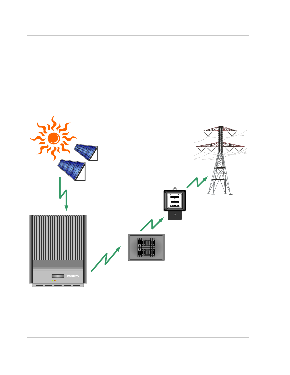
The Xantrex Grid Tie Solar Inverter (GT Inverter) is designed to convert solar
electric (photovoltaic or PV) power into utility-grade electricity that can be used
by the home or sold to the local power company.
Installing the GT Inverter consists of mounting it to the wall and connecting the
DC input to a PV array and the AC output to the utility. See Figure 1-1 for a
simple diagram of a typical installation.
In order to operate, the GT Inverter must have grid power available and connected.
It will not provide backup power if the AC grid fails.
Photovoltaic (PV) Panels—
PV Array
Harvested solar energy
DC converted to AC
Grid Tie Sola r In verter
Xantrex GT Inverter
Figure 1-1 Basic System Overview
Main Utility
Service Panel
Power routed to Utility Grid
kWh
00000008
230V 50 Hz10(60)A
Utility Meter
Utility Grid
1–2 975-0253-01-01
Page 19
About the Xantrex Grid Tie Solar Inverter
PV compatibility The G T Invert er is designed to take advantage of solar modules configured as high
voltage PV string arrays—single crystalline, poly crystalline, or thin film—with a
195 to 550 Vdc input voltage Maximum Power Point range (240 to 550 Vdc for
the GT5.0-SP model).
Maximum Power
Point Tracking
(MPPT)
The GT Inverter uses Xantrex proprietary Maximum Power Point Tracking
(MPPT) technology to harvest the maximum amount of energy from the solar
array. MPPT learns your array’s specific characteristics, maximizing its output at
all times.
High efficiency The high-frequency, solid-state design of the GT Inverter is extremely efficient—
up to 96%.
Expandable Multiple GT Inverters may be networked together for increased net metering
capacity or future system growth.
Communications
protocol
The GT Inverter uses the Xanbus
communicate with multiple units connected within the system. For more
®
communications protocol, enabling it to
information, see “Xanbus Network Technology” on page 3–10.
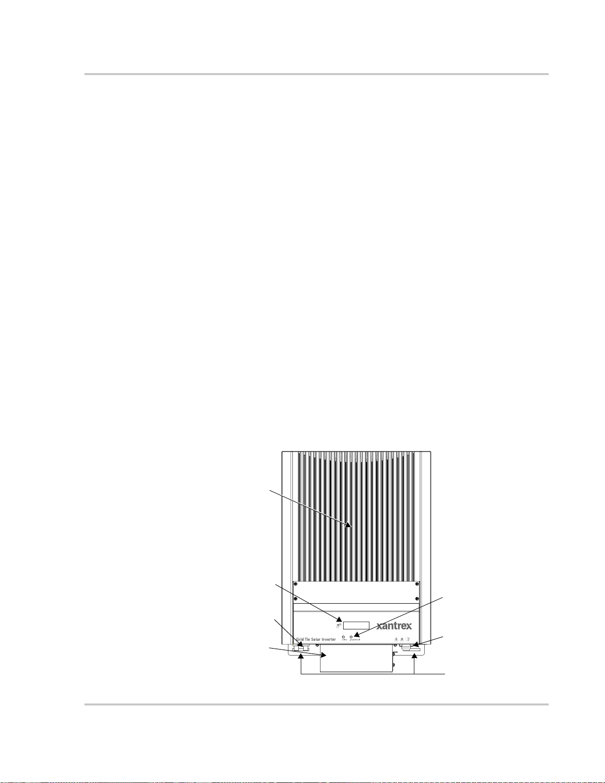
Standard Features
The GT Inverter has the following standard features:
• Sealed inverter (IP54) and external heat sink to protect power electronic
components
• Quick-connect AC and DC connections
• Liquid Crystal Display (LCD) to provide easy-to-read system status and daily
cumulative energy production information
• Two LED indicator lights to provide status and ground fault indication.
Heat sink
LCD
LED indicator lights
DC quick-connects
Communication
ports cover
AC connection
Mounting slots (five)
Figure 1-2
975-0253-01-01 1–3
Main Features of the GT Inverter
Page 20

1–4
Page 21

2
Installation
Chapter 2, “Installation”, provides information about planning for and
installing the GT Inverter. It contains information to help you plan
wire routes, ensure your PV array provides necessary power, and find
a suitable location for installation.
The topics in this chapter are organized as follows:
• “Installation Options” on page 2–2
• “Planning the Installation” on page 2–2
• “Preparing for the Installation” on page 2–9
• “Mounting the Inverter” on page 2–10.
Page 22

Installation
Installation Options
The GT Inverter may be installed as a single inverter for a single PV array of up to
two PV strings (up to three PV strings for the GT5.0-SP model), or in a multiple
inverter configuration for multiple PV arrays (see Figure 2-1 for diagrams of both
options).
Single Inverter Installation
In this configuration, a single inverter collects the harvested solar energy and
routes the power to the main utility service panel and the utility grid.
Multiple Inverter Installations
If multiple inverters are used, each inverter must be wired to an independent PV
array . In this configuration, each inverter collects the harvested solar energy from
a separate PV array and routes the power to the main utility service panel and the
utility grid.
Communications between inverters is optional, but can be enabled by installing
communications cabling to the inverter RJ45 ports. See “Connecting Network
Cable between Inverters” on page 3–13.
Planning the Installation
The following issues need to be considered when planning for an installation
using the GT Inverter. See the specified sections for more information.
• “Inverter Location” on page 2–4
• “PV Array Requirements” on page 2–5
• “Grounding Requirements” on page 2–7
• “Routing the Wires” on page 2–8.
Ensure that you have obtained all permits required by local authorities or utilities
before commencing installation.
2–2 975-0253-01-01
Page 23
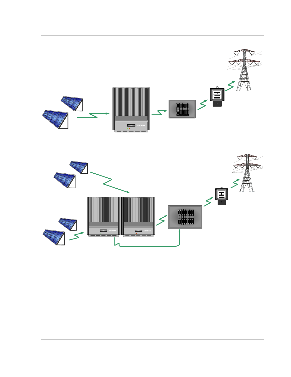
Single Inverter Installation
DC converted to AC
Planning the Installation
Surplus power routed
to Utility Grid
00000008
kWh
230V 50 Hz10(60)A
Utility Meter
Utility Grid
Harvested solar energy
Photovoltaic (PV) Panels—
PV Array
PV Array #2
Photovoltaic Panels—
Multiple PV Arrays
Harvested
solar energy
GT Inverter #1
PV Array #1
Grid Tie Solar Inverter
Grid Tie Solar Inverter
GT Inverter
Multiple Inverter Installation
Harvested solar energy
Grid Tie Solar Inver t e r
GT Inverter #2
DC converted to AC
Main Utility
Service Panel
DC converted to AC
Main Utility
Service Panel
Surplus power routed
to Utility Grid
00000008kWh
230V 50 Hz10(60 )A
Utility Meter
Utility Grid
Figure 2-1
Installation Options Overview
975-0253-01-01 2–3
Page 24

Installation
Inverter Location
WARNING: Burn hazard
Do not install in a location where people can accidentally come into contact with the front
of the inverter. High temperatures can be present on the face of the inverter, causing a
potential burn hazard.
In extreme conditions, the GT Inverter chassis can reach temperatures that can cause skin
burns if accidentally touched. Ensure that the GT Inverter is located away from normal
traffic areas.
Inverter failure due to improper installation will void the inverter warranty.
Consider the following when determining where to install the inverter.
Fire Safety
Indoor/
Outdoor
Orientation
Temperature
Ground
Clearance
Distance
• Do not install anywhere near combustible or flammable materials such
as wooden cabinets and furniture, or stored fuels and solvents.
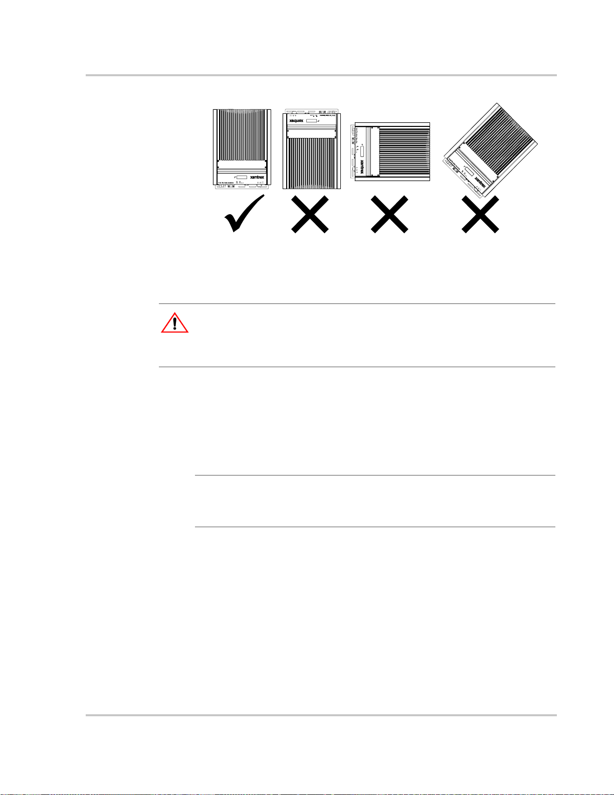
• The GT Inverter can be mounted indoors or outdoors. When installed
outdoors, the GT Inverter must be mounted in a vertical orientation.
• In outdoor installations the GT Inverter should be located away from
lawn sprinklers and other sources of spray.
• The GT Inverter must be mounted vertically (with DC and AC
connectors facing down) on a wall or pole. See Figure 2-2.
• Ensure that the GT Inverter is mounted in a location where the
ambient temperature range is -25 to 65 °C.
• At extreme cold temperatures, the front panel LCD may not function
normally. At higher temperatures, the unit may derate power. See
“Environmental Specifications” on page A–5 and “Output Power vs.
Ambient Temperature” on page A–4.
• Outdoors, the GT Inverter requires at least 100 cm of clearance
between the bottom of the unit and the ground. This clearance helps
prevent water from splashing onto the bottom of the unit.
• Install the GT Inverter at a height at which the LCD is easily readable.
• To minimize copper losses, ensure that wire lengths between the PV
array and the GT Inverter and between the inverter and the Main
Utility Service Panel are kept to a minimum.
• Maximum distances will depend on wire gauges used and PV array
output voltages.
Debris free
2–4 975-0253-01-01
• Excessive debris (such as dust, leaves, and cobwebs) can accumulate
on the unit, interfering with wiring connections and ventilation. Do
not install in a location where debris can accumulate (such as under a
tree).
Page 25
Planning the Installation
Figure 2-2
GT Inverter mounting orientation
PV Array Requirements
WARNING: Shock hazard
Whenever a PV array is exposed to sunlight, a shock hazard exists at the output wires or
exposed terminals. To reduce the risk of shock during installation, cover the array with an
opaque (dark) material before making any connections.
General Recommendations
It is important that the PV array is installed correctly to the manufacturer’s
specifications and to local code requirements.
Equipment and Installation Recommendations
Important:
small obstructions such as antennas, chimneys, and power lines. As well, be aware of
potential obstructions from growing trees and neighboring buildings. A small amount of
shade can have a disproportionately high impact on system performance.
The PV array should be free of shade. This requirement includes even
Equipment
recommendations
• All electrical equipment should be approved for the voltage and current
ratings necessary for the application.
• All wiring should be sized correctly to minimize voltage drop.
• All exposed wires or conduits should be sunlight resistant.
• All required overcurrent protections should be included in the system and
accessible for maintenance.
Installation
recommendations
• All electrical terminations should be fully tightened, secured, and strain
relieved as appropriate.
• All mounting equipment should be installed according to the manufacturer’s
specifications.
• All wires, conduit, exposed conductors and electrical boxes should be secured
and supported according to code requirements.
975-0253-01-01 2–5
Page 26
Installation
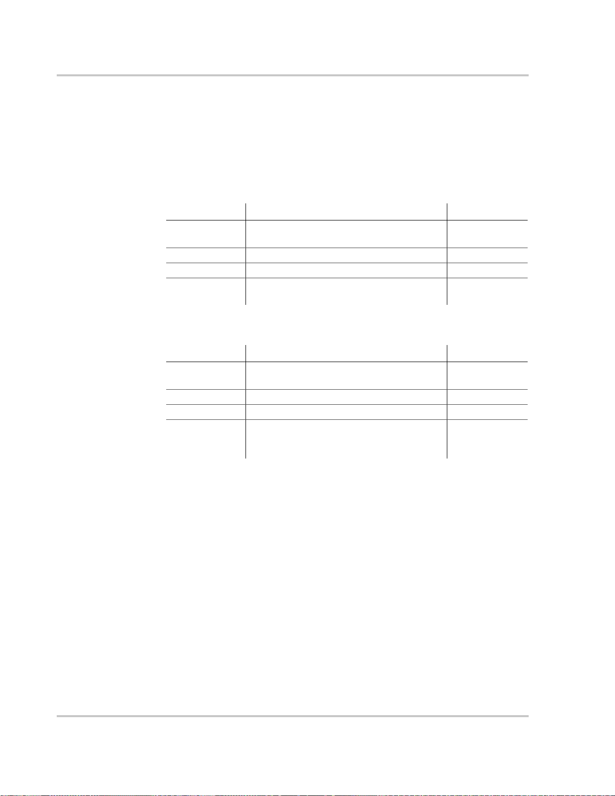
Voltage and MPPT Requirements
MPPT operational
window
The MPPT software maximizes the output energy of solar arrays as long as the
operating voltage is within the MPPT operational window. Ensure that the PV
array used in the system operates within the MPPT operational window.
Effects of array voltages outside of the MPPT operational window are shown in
Table 2-1.
Table 2-1
Voltage Effect of Array Voltage Inverter Mode
< 195 Vdc Operating voltage shifts to 195 Vdc; the array is
195 to 550 Vdc Maximum harvest of solar energy MPPT window
550 to 600 Vdc Reduced harvest of solar energy Power derating
> 600 Inverter stops selling surplus energy and shuts
Table 2-2
Voltage Effect of Array Voltage Inverter Mode
< 240 Vdc Operating voltage shifts to 240 Vdc; the array is
240 to 550 Vdc Maximum harvest of solar energy MPPT window
550 to 580 Vdc Reduced harvest of solar energy Power derating
> 580 Inverter stops selling surplus energy and shuts
MPPT Operational Window
Low power
not at its maximum power point
Shutdown
down. Higher voltage may damage the inverter.
MPPT Operational Window (GT5.0-SP)
Low power
not at its maximum power point
Shutdown
down. Voltage above 600 Vdc may damage the
inverter.
Voltage
requirements
The maximum power point voltage of a string connected to the GT Inverter should
be a minimum of 195 Vdc (240 Vdc for GT5.0-SP). If it is less than 195/240 Vdc,
the inverter will continue to operate, but it will regulate the PV voltage to
195/240 V. Because the array will not be operating at its maximum power point,
this may result in lower than expected energy harvest.
Maximum PV
Power
The solar array should be sized such that its maximum power output does not
exceed the limits of the MPPT operational window (195/240 to 550 Vdc). See
“Guidelines for Matching PV Array Size to Xantrex Grid Tie Solar Inverter
Input”.
The array voltage should never exceed 600 V
(open circuit voltage) under any
OC
thermal condition.
Likewise, ensure that the I
(short circuit current) rating of the array at any
SC
temperature does not exceed the short circuit current rating of the inverter.
2–6 975-0253-01-01
Page 27
Planning the Installation
Guidelines for Matching PV Array Size to Xantrex Grid Tie Solar Inverter Input
For determining the number of panels required in the PV string (panels connected
in series), you must ensure that the following three requirements are met:
1. To avoid damage to the inverter, ensure that the PV array output will never
exceed 600 Vdc under any conditions.
2. Do not exceed the maximum array short circuit-current rating marked on the
inverter.
3. To achieve maximum energy harvest from your array, ensure that the V
(voltage at maximum power) does not drop below 195/240 Vdc or increase
above 550 Vdc under most conditions.
Guidelines to help you meet these requirements:
• Consider the expected V
panel manufacturer provides a V
25 °C. Ensure that the V
exceed 600 V
. Panel voltage increases in cold temperatures—the panel
OC
manufacturer should be able to provide a coefficient of voltage increase per
degree.
• Panel voltage decreases in high temperatures. This will affect the panels’
V
. Again, the manufacturer’s coefficient must be used with the highest
MP
expected temperature to determine the minimum V
Once you know the specifications of your panels, all these factors will help
determine the maximum and minimum number of panels that can be used.
of the string under all possible conditions. The
OC
rating per panel, but it is usually rated at
OC
rating at the coldest ambient temperature does not
OC
.
MP
MP
Visit the
Grounding Requirements
WARNING: Shock hazard
The GT Inverter must be grounded by connection to a grounded permanent wiring system.
AC Grounding
AC grounding is governed by local codes. Consult the local utility for specific
grounding requirements.
DC Grounding
The GT Inverter is designed to work with ungrounded PV arrays.
Support
page at
www.xantrex.com
to use an online PV array sizing tool.
975-0253-01-01 2–7
Page 28

Installation
Lightning Protection
Routing the Wires
Reduce the risk of lightning damage by using a single-point grounding system. In
this system, all ground lines terminate at the same point. This point normally is the
main utility ground installed by the utility company to provide a ground for the
house wiring. This ground usually consists of a copper rod driven 1.5 to 2.5
meters into the earth.
Typical
configurations
Determine all wire routes to and from the GT Inverter. Typical routing
configurations include:
• AC wiring from the GT Inverter to the main utility service panel
• DC input wiring from the PV array to the GT Inverter
All wiring and installation methods should conform to applicable electrical and
building codes.
For all installations, local utilities may have additional requirements.
WARNING: Shock hazard
Check for existing electrical or plumbing prior to drilling holes in the walls.
2–8 975-0253-01-01
Page 29

Preparing for the Installation
Ensure your local utility is consulted for any requirements for connecting to or
returning power to the grid. Obtain all permits necessary to complete the
installation. Consult your local and national el ectric al codes for more information.
Preparing for the Installation
Important:
DC wiring/cabling and wires/cables.
In this manual “wiring” and “wires” are used in reference to both AC and
Wiring
Wire size and length will be determined by the location of each component and
their relative distance to each other. W ire sizes may also be affected by whether or
not conduit is used.
Important:
Ensure that wiring is not undersized. Undersized wiring can result in significant power
losses and reduction in system efficiency.
Wire size should be based on the maximum power rating of the inverter.
AC Circuit Breaker Requirements
The main utility service panel must dedicate a double pole breaker for each
inverter installed. This breaker must be capable of handling the rated maximum
output voltage and current of the inverter (see “Electrical Specifications” on
page A–2).
AC and DC Disconnects
Depending on the installation, external AC and/or DC disconnects may be
required, and they may need to be in a location easily accessible to utility or fire
personnel. Consult local codes and authorities for additional information.
WARNING: Shock hazard
Never connect or disconnect the PV modules from the G T Inverter under load (by pulling
the PV quick connects before disconnecting the grid). Always disconnect the GT Inverter
from the grid first.
975-0253-01-01 2–9
Page 30
Installation
Mounting the Inverter
Overview
WARNING: Fire, shock and energy hazards
Before installing the GT Inverter, read all instructions and cautionary markings located in
this manual, on the PV array, and on the main service panel.
General installation
steps
Installing of the GT Inverter includes these main steps:
1. Mounting the GT Inverter (this chapter)
2. Making the DC connections from the PV array to the GT Inverter
(“Connecting the DC Wiring” on page 3–2)
3. Making the AC connections from the GT Inverter to the main utility service
panel (“Connecting the AC Wiring” on page 3–7)
Figure 2-3 summarizes these steps.
PV Array
kWh
00000008
230V 50 Hz10(60)A
600 Vdc
2
Open Circuit
Maximum
Utility Meter
3
Line1
Line2
Protective Earth
Utility Grid
Grid Tie S olar Invert er
1
Xantrex GT Inverter
Figure 2-3
Installation Overview
Main Utility
Service Panel
2–10 975-0253-01-01
Page 31

Mounting the Inverter
This chapter describes the first step: mounting the inverter and installing
accessories.
Mounting steps Instructions for mounting the GT Inverter are described in the following sections:
• “Installing the Mounting Bracket” on page 2–12
• “Mounting the Inverter on the Bracket” on page 2–16.
Tools and Materials Needed
• Assorted screwdrivers, drill, etc.
•Level
• Mounting support material, such as plywood or poles
• Wood screws, anchors for screws, depending on mounting surface.
Dimensions
The dimensions of the inverter are shown in Figure 2-4.
137
403
522
552
Flange and
97
mounting slots
Communication ports cover (attach after
mounting and wiring are complete)
All dimensions in mm.
598
Figure 2-4
GT Inverter Dimensions (GT5.0-SP shown)
CAUTION
For the inverter to meet regulatory requirements, the communication ports cover must be
installed.
975-0253-01-01 2–11
Page 32

Installation
Installing the Mounting Bracket
The mounting bracket for the G T Inverter allows the unit to be easily mounted and
removed for servicing. It has one hook that matches a corresponding hook on the
back side of the inverter.
238 mm
183 mm
Rectangular slots × 8:
8 mm × 30 mm
Mounting flanges
Figure 2-5
Clearance Requirements
For optimal and safe operation, ensure there is adequate clearance around the
inverter. The minimum clearance recommendations in Table 2-3 assume a vertical
mounting. If clearances are less than these recommendations are used, additional
power reduction may occur at high ambient temperatures.
Table 2-3
Location Minimum Clearance
Above 30 cm
Below:
•Inverter
• Bracket
In front Sufficient room to allow for easy access to read the display and to prevent
On sides
Mounting slots for securing the inverter
Mounting Bracket and GT Inverter
Inverter Clearance Requirements
Outdoors:
• 100 cm
• 130 cm
Indoors: the same clearances are recommended but not required.
accidental contact with hot surface.
Units can be mounted side by side with no clearance between them, but
15 cm of clearance around the ou termost two units is recommended. In hot
climates, some clearance betw ee n un it s may be needed to prevent thermal
derating.
2–12 975-0253-01-01
Page 33

Surfaces for Mounting
Mounting to
concrete surface
Mounting on poles
or rails
Mounting to
wallboard with
support
Mounting to siding
using wall studs
Mounting the Inverter
WARNING: Shock hazard
Before drilling holes to mount the GT Inverter, ensure there are no electrical wires or
plumbing in this area.
WARNING: Personal injury
The G T Inverter weighs approximately 20 kg. Always use proper lifting techniques during
installation to prevent personal injury.
WARNING: Explosion hazard
Do not store combustible or flammable materials anywhere near the inverter.
The GT Inverter weighs approximately 20 kg. The supporting surface must be
strong enough to handle 75 kg. If the supporting surface is not strong enough to
handle that weight, then supporting material such as a sheet of plywood can be
used to enhance the strength of the mounting surface.
The GT Inverter can be mounted to a vertical surface such as wallboard, wood
siding, brick, concrete wall or pole assembly.
• If mounting the unit on a concrete surface using anchors with no supporting
material, use four screws and anchors, instead of two, to adequately secure the
unit and distribute the weight.
• See “Mounting on Poles or Rails” on page 2–14. Ensure the bottom o f the unit
is a minimum of 100 cm from the ground if mounted outdoors.
• Installation onto wallboard requires either the use of a supporting material
such as plywood or securing the mounting screws to supporting wall studs.
Use at least two screws and anchors to secure the unit to the supporting
material.
• If mounting to exterior siding using a wall stud for support, the plywood
backing will not be needed. Use at least two lag screws to secure the unit to
the supporting material. Ensure the screws enter the stud at least 40 mm to
adequately support the weight of the unit. After securing the bracket, the
screws or bolts and washers should protrude no more than 6 mm from the
bracket surface.
Important:
the GT Inverter. It is recommended to use 6 mm diameter fasteners. However, because
mounting surfaces can vary, installers must select appropriate hardware for each
installation.
Important:
or other high-risk areas.
975-0253-01-01 2–13
Other than the mounting bracket, no mounting hardware is supplied with
Local codes may impose additional mounting requirements in earthquake
Page 34

Installation
Mounting on Poles or Rails
To mount the unit using poles:
1. Ensure that poles or rails are securely assembled in place. If using horizontal
rails, two rails are required: one for the mounting bracket and another for
securing the bottom edge of the inverter (see Figure 2-6).
2. Connect the mounting bracket vertically to the pole or rail:
• Be sure to use at least two bolts to secure the bracket to the support.
• Position the lower edge of the bracket a minimum of 130 cm above the
• Position the top edge of the bracket a minimum of 34 cm below any
3. If using a single vertical pole, ensure that the inverter is secure and unable to
rotate around the pole.
floor or ground.
ceiling or roof.
Figure 2-6
Mounting bracket
At least 2 bolts to
secure bracket to
poles/rails.
130 cm
For securing
the bottom of
the inverter
Ground/Floor
Examples of Mounting on a Pole or Rails
34 cm
46 cm
100 cm
2–14 975-0253-01-01
Page 35

Mounting on Wallboard, Brick or Concrete
To mount the GT Inverter to wallboard, brick, or concrete:
1. Locate the area where the GT Inverter is to be installed.
2. Install backing support material if required.
At least 2 screws
with washers to
secure bracket
to wall.
Mounting the Inverter
34 cm
≥165 mm
Ground/floor
Figure 2-7
130 cm
Ground/floor
Single GT Inverter Multiple GT Inverters
130 cm
Installing the Mounting Bracket using Plywood Support
3. Using a level, place the mounting bracket against the wall surface so that the
bottom edge of the bracket is at least 130 cm above the ground. Position the
top edge of the bracket a minimum of 34 cm below any ceiling or roof. See
Figure 2-7.
4. Mark the location for mounting screws if using a wall stud for support. At
least four mounting screws and anchors are needed for concrete installations
or wallboard installations where no wall studs are available for support.
5. Remove the bracket and drill the holes using an appropriately sized drill bit.
Drill appropriately sized holes for screws or anchors.
6. Secure the bracket to the supporting surface using at least two screws and
washers.
975-0253-01-01 2–15
Page 36

Installation
Mounting the Inverter on the Bracket
Before mounting the inverter, remove the communication ports cover (if it has
been attached to the unit). With the cover removed, you can access all the
mounting slots along the bottom flange. Ensure the communication ports cover is
installed after mounting and wiring are completed.
Mounting a Single Inverter
To mount the inverter on the mounting bracket:
1. Place the GT Inverter’s mounting hook, located on the back of the enclosure,
over the bracket and ensure the inverter is seated properly, as shown in
Figure 2-8.
2. After the unit is correctly seated on the bracket hook, locate the mounting
slots at the bottom of the unit, and mark the location on the wall for securing
screws.
3. Remove the inverter and drill pilot holes in the wallboard, brick or concrete
for the securing screws.
4. Reinstall the G T Inverter on the bracket and secure the bottom of the unit with
appropriate screws or anchors, and tighten.
Slide the mounting hooks on the inverter
over the hooks on the mounting bracket.
Flange with
mounting slots
130 cm
Ensure the inverter is
seated properly on the
mounting bracket
100 cm
Figure 2-8
2–16 975-0253-01-01
Proper Placement of the Inverter on the Mounting Bracket
Page 37

3
Wiring the Inverter
Chapter 3, “Wiring the Inverter”, provides procedures for making DC
and AC wiring connections for single and multiple inverter
installations. This chapter also includes information about
communications wiring and using GT-View monitoring software.
The topics in this chapter are organized as follows:
• “Connecting the DC Wiring” on page 3–2
• “Connecting the AC Wiring” on page 3–7
• “Connecting Multiple Inverters” on page 3–6
• “Communications Wiring for Multiple Inverters” on page 3–10
Page 38

Wiring the Inverter
Connecting the DC Wiring
The GT Inverter is equipped with four PV quick connects (two positive, two
negative) for connecting up to two PV strings. The GT5.0-SP model has six PV
quick connects for connecting up to three PV strings.
GT2.5-DE, GT3.8-DE, GT2.8-SP, GT3.8-SP
Figure 3-1
PV positive (+)
Multi-Contact connector
PV positive (+)
Multi-Contact connector
PV Quick Connect Locations
WARNING: Shock hazard
Whenever a PV array is exposed to sunlight, a shock hazard exists at the output wires or
exposed terminals. Cover the PV arrays with opaque material before commencing any
wiring.
WARNING: Shock hazard
Before wiring the G T Inverter , ensure the main br eaker in the primary utility breaker box
is switched OFF . Switch this breaker ON only after al l wiring is completed as instructed in
the procedures.
PV negative (–)
Multi-Contact connector
GT5.0-SP
PV negative (–)
Multi-Contact connector
AC quick connect
(see page 3–7)
AC cable gland
(see page 3–7)
WARNING: Fire hazard
For G T 5.0-SP models, when three PV strings are connected, ensure that internal DC fuses
are installed and that the two positive internal DC wires are relocated from their
factory-installed connection points to connection points in line with the DC fuse clips. The
third positive DC wire must remain connected in line with the DC fuse clip as it came
from the factory. See Figure 3-2. Without proper fusing, a fire hazard can exist if a
short-circuit condition occurs in one PV string.
3–2 975-0253-01-01
Page 39

CAUTION: Equipment damage
Improper wiring may cause permanent damage to the GT Inverter. Take special care to
ensure the positive (+) and negative (–) wires from a single array connect to the same
inverter.
Equipment Needed
• Conduit for wire runs and appropriate fittings/bushings
• Wire cutters/wire crimpers/wire strippers
• Digital voltmeter
• Frequency counter (optional, for troubleshooting)
• Female and male DC cable connectors to mate with the Multi-Contact
connectors PV-ADSP3/GWD (positive) and PV-ADBP3/GWD (negative) on
the GT Inverter. You will need two connectors (one female and one male) for
each PV string (you can connect up to two PV strings to the GT Inverter).
DC Fuses (GT5.0-SP Model Only)
Connecting the DC Wiring
The GT5.0-SP DC interconnect board has three fuse clips for DC fuses to provide
additional overcurrent protection. DC fuses must be installed when connecting a
third PV string to the unit. The fuses must be approved (CE marked) 10 × 38 mm
fuses rated for 600 Vdc or over, with an ambient temperature rating of 40 °C. You
can also derate the fuses for your installation’s ambient temperature at full power.
The maximum total input current is 24 A. The maximum current allowed per
string (that is, for any single PV input) for the GT5.0-SP model is 15 A, whether a
fuse is used or not. When calculating fuse size, do not exceed the rated maximum
input current or the maximum current per string. Using the same fuse value in
each string is recommended.
Table 3-1
Manufacturer Model
SIBA 5019906.4, 5019906.6, 5019906.8, 5019906.10, 5019906 .12
Littelfuse KLKD 001., KLKD 01.5, KLKD 002., KLKD 02.5, KLKD 003.,
Ferraz Shawmut DCT5-2, DCT8-2, DCT10-2, DCT12-2, DCT15-2
Bussmann FWC-6A10F, FWC-8A10F, FWC-10A10F, FWC-12A10F
Recommended Fuses
KLKD 03.5, KLKD 004., KLKD 005., KLKD 006., KLKD 007.,
KLKD 008., KLKD 009., KLKD 010., KLKD 012., KLKD 015.
Install the DC fuses before connecting the PV array. When installing the DC
fuses, the two positive PV wires must be relocated from their factory-installed
connection points to the connection points in line with the DC fuse clips. See
Figure 3-2.
975-0253-01-01 3–3
Page 40

Wiring the Inverter
When connecting
three PV strings,
positive wires must
be relocated and
fuses installed.
The DC interconnect board is inside the GT Inverter wiring compartment. To
access the wiring compartment, remove the inverter front panel. It is held in place
by four screws—two along the bottom and two on the front of the inverter.
GT5.0-SP DC interconnect board
with factory-installed wiring.
Figure 3-2
GT5.0-SP DC Fuse Installation
Connecting the PV Array
The following procedure is illustrated in Figure 3-3. If there will be more than one
PV string, label the positive and negative wire pairs appropriately (for example:
PV 1, PV 2).
GT5.0-SP models are factory configured to accept two PV strings. To connect a
third PV string, relocate the two positive internal DC wires from their
factory-installed connection points to connection points in line with the DC fuse
clips, and install DC fuses as specified in “DC Fuses (GT5.0-SP Model Only)” on
page 3–3. See Figure 3-2.
To wire the PV array to the GT Inverter:
1. If necessary, install DC conduit from the PV string(s) to the GT Inverter.
2. Terminate the wires coming from the PV string(s) with appropriate
Multi-Contact connectors.
CAUTION: Equipment damage
Before connecting the PV array to the inverter, check to ensure correct polarity and that
the voltage between the positive (+) and negative (–) is below 600 Vdc (U
To check the PV array DC voltage:
1. Uncover the PV arrays and expose them to full sunlight. The sunlight must be intense
enough to produce the required output voltage.
2. Measure the PV array open circuit DC voltage across the DC positive (+) and negative
(–) terminals. This voltage must be less than 600 Vdc. Voltage over 600 Vdc will damage
the inverter.
3. Cover the PV arrays with an opaque material again.
GT5.0-SP DC Interconnect Board with positive
PV wiring reconfigured for DC fuses.
≤600 Vdc).
PV
3–4 975-0253-01-01
Page 41

Connecting the DC Wiring
3. Connect the POSITIVE (+) wire from the #1 PV string to a GT Inverter PV
positive (+) quick connect.
4. Connect the NEGATIVE (–) wire from the #1 PV string to a GT Inverter PV
negative (–) quick connect.
5. If necessary, repeat for the #2 or (for GT5.0-SP) #3 PV string. Double check
that the wires are in the proper locations.
If only one PV string connection is used, cover the unused PV quick connects
with the seals provided.
WARNING: Shock hazard
Never connect or disconnect the PV modules from the G T Inverter under load (by pulling
the PV quick connects before disconnecting the grid). Always disconnect the GT Inverter
from the grid first.
PV Array
–
+
PV String #2
–
+
PV String #1
Xantrex GT Inverter
Figure 3-3
Important:
box may be required. The installer must provide this equipment.
DC Connections for a Two-String PV Array
Depending upon installation and local codes, fusing and/or a combiner
975-0253-01-01 3–5
Page 42

Wiring the Inverter
Connecting Multiple Inverters
For installations with multiple inverters, a separate PV array is required for each
GT Inverter unit. The output of each GT Inverter feeds a separate dual-pole circuit
breaker in the main utility service panel.
When connecting multiple inverters, complete the wiring and perform the
commissioning procedure for each inverter one at a time. For wiring instructions,
see “Connecting the DC Wiring” on page 3–2 and “Connecting the AC Wiring”
on page 3–7. For the commissioning procedure, see page 4–2.
WARNING: Shock hazard and equipment failure
If inverters “share” more than one PV array, an input current difference of over 1 A
between arrays can cause short circuit failure in each inverter. This failure will also
generate hazardous voltages around each unit.
In multiple inverter installations, it is very important to ensure each inverter is correctly
connected to its own PV array(s) and that no wires are crossed. For example, connect PV1
positive (+) and PV1 negative (–) to inverter 1 and PV2 positive (+) and PV2 negative (–)
to inverter 2.
Do not connect PV1 positive (+) and PV2 negative (–) to inverter 1 and PV2 positive (+)
and PV1 negative (–) to inverter 2. See Figure 3-4.
Figure 3-4
–
+
PV Array #1
GT Inverter #1
Improper Multiple Inverter Connections
–
+
PV Array #2
GT Inverter #2
3–6 975-0253-01-01
Page 43
Connecting the AC Wiring
WARNING: Shock hazard
AC utility wiring to the GT Inverter unit is performed directly at the main breaker panel.
This should be done only by a qualified installer or electrician.
WARNING: Shock hazard
Before wiring the G T Inverter , ensure the main br eaker in the primary utility breaker box
is switched OFF . Switch this breaker ON only after all wiring is completed as instructed in
the procedures.
The GT Inverter can be connected to a single bi-directional meter, or to dual
meters, where one meter indicates power used and the second meter indicates
power sold (power supplied back to the utility). Consult the local utility to
determine the proper components to install, and obtain any permits required prior
to installation.
The GT Inverter must be connected to the utility with three wires—two lines (one
high phase and one neutral/low phase) and one protective earth (ground).
Connecting the AC Wiring
Making AC Connections for GT2.5-DE, GT3.8-DE, GT2.8-SP, GT3.8-SP Models
GT Inverter models GT 2.5-DE, GT 3.8-DE, 2.8-SP, 3.8-SP are equipped with a
quick connect for making AC connections. To make AC connections using the
quick connect, you must first prepare the wiring between your utility panel and
the GT Inverter.
You will need:
• Wire strippers
• Small (3 mm or less) slot-head screwdriver
The AC wiring from the utility panel must be terminated with a Binder Female
cable connector (Binder Series 693 part number 99-4222-14-04) before being
connected to the AC quick connect on the GT Inverter.
To prepare the AC wiring:
1. If necessary, strip 10 mm of insulation on the three wires from the utility
panel.
2. Unscrew the female terminal from the casing of the female cable connector.
See Figure 3-5.
3. Unscrew the other components of the female cable connector.
4. Run the wires through the pressing screw, pinch ring, seal, and shell of the
female cable connector.
5. On the female terminal, connect the protective earth wire to the terminal
marked with the symbol. See Figure 3-6.
975-0253-01-01 3–7
Page 44

Wiring the Inverter
6. Connect the neutral (grid low, zero conductor) wire to the terminal marked
with 1.
7. Connect the other phase L wire to the terminal marked with 2.
Terminal 3 is not used.
8. After ensuring all the wires are tightened in their terminals, screw the casing
onto the female terminal.
9. Replace the remaining components of the female cable connector, ensuring a
tight seal.
10. Tighten the pressing screw.
Pinch ring
AC connector terminals
(see Figure 3-6)
Shell
Seal
Female terminal
Notch
Figure 3-5
Phase L wire
Neutral wire
Figure 3-6
Outer ring
AC Connector (Fem ale)
Not used
Protective Earth
wire
AC Connector Terminals
Pressing screw
To connect the AC connector to the GT Inverter:
1. Line up the notch on the female AC cable connector with the connector on the
GT Inverter.
2. Insert the AC cable connector into the connector on the GT Inverter.
3. Secure the connector by turning the outer ring.
CAUTION
For the inverter to meet regulatory requirements, the communication ports cover must be
installed. If no communications wiring is required, install the communication ports cover
when all DC and AC connections are complete (see Figure 3-12).
3–8 975-0253-01-01
Page 45
Making AC Connections for GT5.0-SP Model
AC wiring to the GT5.0-SP model is connected directly to the AC terminal block
then secured with the supplied cable gland.
You will need:
• Wire strippers
• Slot-head screwdriver
To connect the AC wiring:
1. If necessary, strip 1 0 mm of insulatio n on the thr ee wires from th e utility panel.
2. Remove the inverter front panel. It is held in place by four screws—two along
the bottom and two on the front.
The AC wiring compartment is behind the front panel.
Connecting the AC Wiring
Figure 3-7
3. Loosen, but do not remove, the AC cable gland cap nut.
4. Pass the three wires from the utility panel through the cable gland and into the
wiring compartment.
5. Loosen the appropriate terminals and insert the wires into the terminals.
a) Connect the protective earth wire to a terminal marked with
b) Connect the neut ral (grid low, zero conductor) wire to a terminal marked
c) Connect the other phase L wire to a terminal marked with ~.
Either 230 V/50 Hz line can go to either ~ terminal.
6. Tighten the terminals to a torque of 1.45 to 1.55 Nm.
7. Allowing the wires an appropriate amount of slack within the wiring
compartment, tighten the cable gland cap nut to a torque of 4 Nm, creating a
tight seal.
8. Re-attach the inverter front panel.
975-0253-01-01 3–9
GT5.0-SP AC Wiring Compartment and Terminal Block
.
with ~.
Page 46
Wiring the Inverter
Communications Wiring for Multiple Inverters
Communications wiring between multiple GT Inverters allows information about
each inverter and its associated PV array to be communicated between all of the
inverters in the system. Information about the entire system can be displayed on
any inverter LCD in the system.
For example, in a two-inverter system, if inverter #1 is producing 1500 W and
inverter #2 is producing 2000 W, both inverters display a total system power of
3500 W. The cumulative energy produced by both inverters that day is also
displayed.
You can still view information for an individual inverter in a system. See “T o view
unit-specific screens in a multiple unit system:” on page 5–7.
Without communications wiring, each inverter in a system displays information
only for the unit and its associated PV array.
Xanbus Network Technology
GT Inverters are Xanbus-enabled devices. They use Xanbus (a communications
protocol developed by Xantrex) to communicate with other GT Inverters. Each GT
Inverter is connected by an Ethernet cable, as shown in Figure 3-8.
TerminatorTerminator
Figure 3-8
Ethernet cables
Network Layout (Communication Ports Cover Not Installed)
CAUTION: Equipment damage
Connect only Xanbus-enabled devices.
Although the cabling and connectors used in this network system are the same as Ethernet
connectors, this network is not an Ethernet system. Equipment damage may result from
attempting to connect Xanbus to different systems.
3–10 975-0253-01-01
Page 47

Communications Wiring for Multiple Inverters
Network Components
Terminators Network terminators (Figure 3-9) are required at both ends of the network to
ensure the communication signal quality on the network. Network terminators are
inserted into a GT Inverter RJ45 (Xanbus) port. The GT Inverter comes with one
network terminator pre-installed.
GT Inverter Xanbus
ports
Figure 3-9
T wo RJ45 p orts are provided on the GT Inverter for making network connections.
See Figure 3-10 for the location of these ports.
Figure 3-10
Network Terminator
RJ11 ports
(not used)
Xanbus
RJ45 ports
Location of Xanbus RJ45 Ports
RS-232 port (used to connect a PC to
use GT-View. See page 3–14.)
Network cables The network uses Category 5 (CAT 5 or CAT 5e) cable, a standard Ethernet cable
available from any computer supply store.
CAUTION: Equipment damage
Do not use crossover cable in a Xanbus system.
Figure 3-11
975-0253-01-01 3–11
Network Cable
Page 48

Wiring the Inverter
Purchasing Network Components
Consult your system designer to determine what network components will be
needed for your specific installation. Table 3-2 provides a partial list of network
components and part numbers. Pre-made cables are available in lengths from 0.9
to 22.9 metres.
Call your dealer or visit www.xantrex.com for information on purchasing
network components.
Table 3-2
Network Component Part Number
Network termination — Male (2 per pack) 809-0901
Network cable 0.9 m 809-0935
Network cable 1.5 m 809-0936
Network cable 2.0 m 809-0937
Network cable 3.0 m 809-0938
Network cable 4.3 m 809-0939
Network cable 7.6 m 809-0940
Network cable 15.2 m 809-0941
Network cable 22.9 m 809-0942
Network Components and Part Numbers
Guidelines for Routing the Network Cables
WARNING: Shock hazard
:
Do not route the network cables in the same conduit or panel as the AC and DC power
cabling.
To ensure maximum performance of your network, follow these guidelines when
routing the network cables. Route the cables before installing Xanbus-enabled
devices.
• Route the cables away from sharp edges that might damage the insulation.
Avoid sharp bends in the cable—no less than a 100 mm radius.
• Allow for some slack in the cable tension.
• Keep the alignment of wire pairs inside the sheath as straight as possible.
• Allow separation between data and power cables (d ata cables should only
cross a power cable at right angles).
• Do not staple the cable with metal cable staples. Use the appropriate hardware
fasteners to avoid damage to the cable.
CAUTION: Unpredictable device behavior
Do not connect one end of the network to the other to make a ring or loop.
3–12 975-0253-01-01
Page 49

Connecting Network Cable between Inverters
This procedure assumes only two inverters are installed. However, there can be up
to ten inverters wired in this configuration.
To provide communication between multiple inverters:
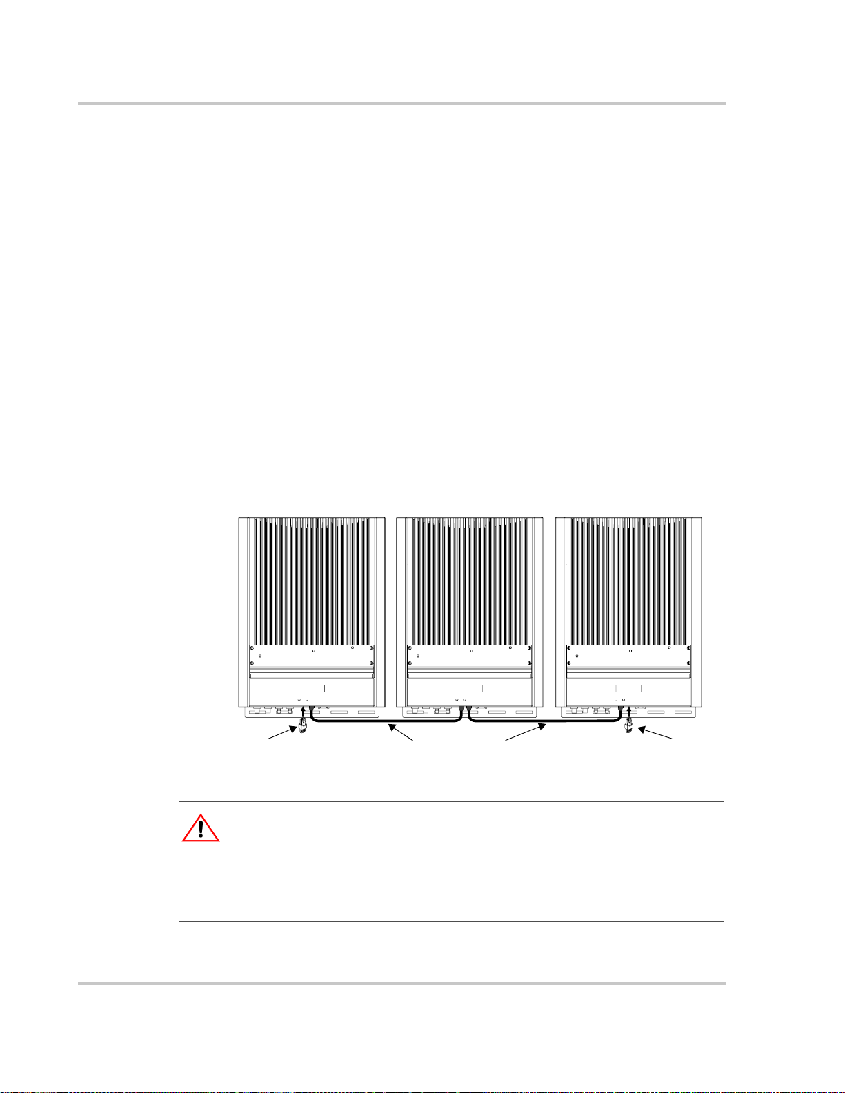
1. Remove the communication ports covers from all inverters. See Figure 3-12.
1. Connect the network cable to an empty RJ45 port in Inverter #1.
2. Pass the cable through the cable clamp on the communication ports cover of
Inverter #1.
3. Pass the cable between Inverter #1 and Inverter #2, securing the cable
appropriately.
4. Pass the cable through the cable clamp on the communication ports cover of
Inverter #2.
5. Connect the network cable to an empty RJ45 port in Inverter #2.
6. For more than two inverters, continue connecting cable as described above.
7. If not already installed, insert male network terminators into the empty RJ45
ports in the inverters at the beginning and end of the network.
After connecting network cables and inserting terminators, there should be no
empty RJ45 ports in any connected inverter.
8. After completing network cabling, tighten all cable clamps (ensuring there is
adequate slack in the cable tension) and replace the communication ports
covers on all units. See Figure 3-12.
Communications Wiring for Multiple Inverters
CAUTION
For the inverter to meet regulatory requirements, the communication ports cover must b e
installed.
Cable clamp
Figure 3-12
975-0253-01-01 3–13
Replacing the Communication Ports Cover
Page 50

Wiring the Inverter
Communications Wiring for Monitoring a Single Inverter
You can view GT Inverter operational data on a personal computer using the
Xantrex GT Solar Inverter Viewer (“GT-View”), which you can download free of
charge at www.xantrex.com.
To use GT-View, you must connect your computer’s serial port to the GT Inverter
RS-232 port (see Figure 3-10).
T o connect your computer to the GT Inverter, you must use a serial DB9 “straight
through” cable.
The RS-232 connector on the GT is configured as follows:
• Pin 2: transmit
• Pin 3: received
• Pin 5: ground.
All other pins are unused.
To connect a single GT Inverter to a personal computer:
1. With DC and AC power disconnected from the inverter, remove the comm
port cover.
2. Plug the male end of the serial cable into the GT Inverter RS-232 port.
3. Pass the female end of the serial cable through the cable clamp on the comm
port cover.
4. Replace the comm port cover.
5. Plug the female end of the serial cable into your computer’s serial port.
6. Restore DC and AC power to the inverter.
When power is restored to the GT Inverter, you can run GT-View on your
computer to monitor the inverter’s operation.
Note: In multiple installations, GT-View monitors only the inverter to which the computer is
connected. However, if the inverters are connected with a Xanbus cable, GT-View will display
total system wattage and the accumulated daily energy produced by all inverters. To monitor
multiple inverters, you require multiple DB9 cable connections (one per invert er) to your
computer.
GT-View displays operational data such as power output in AC watts, lifetime
energy produced, and inverter temperature. Data is updated every two seconds
(default setting).
3–14 975-0253-01-01
Page 51

4
Starting the Inverter
Chapter 4, “Starting the Inverter”, contains information on starting up
the Xantrex Grid Tie Solar Inverter and performing a functional test.
The topics in this chapter are organized as follows:
• “Commissioning Procedure” on page 4–2
• “Disconnect Test” on page 4–3.
Page 52

Starting the Inverter
Commissioning Procedure
To ensure that each GT Inverter is wired correctly, each inverter should be wired
individually using the wiring procedures in Chapter 3, and turned on using this
commissioning procedure. Once a single inverter has been commissioned, it
should be turned off and the wiring and commissioning procedures should be
performed for the next inverter. Repeat in this manner until all the inverters in the
installation have been connected.
Perform this commissioning procedure step-by-step for each GT Inverter
installed. Do not attempt to connect all wires to all inverters and turn on all at the
same time.
CAUTION: Equipment damage
Improper wiring may cause permanent damage to the GT Inverter. Take special care to
ensure the positive (+) and negative (–) wires from a single array connect to the same GT
Inverter.
WARNING: Shock hazard
Hazardous voltages are present from two sources. Use extreme caution during startup
procedure. Before applying power to the GT Inverter, ensure all AC and DC wiring is
correct.
WARNING: Shock hazard
Ensure the protective earth (ground) wire from the inverter is connected to Earth before
applying AC. Failure to do so could result in a shock hazard upon touching the enclosure.
Consult the local utility for specific grounding requirements.
To start the GT Inverter:
1. Ensure the AC breaker is off.
2. Ensure the correct multi-contact PV connectors are firmly plugged into the
GT Inverter as described in “Connecting the DC Wiring” on page 3–2.
3. (GT 2.5-DE, GT 3.8-DE, GT 2.8-SP, GT 3.8-SP only) Ensure the AC quick
connect is firmly inserted into the GT Inverter and that the coupling ring is
tight.
4. Uncover the PV array and/or close the main DC disconnect switch, if one is
installed.
Ensure the PV array is producing the required output voltage.
5. Connect the utility grid voltage by switching the AC circuit breaker on.
6. Monitor the startup sequence on the front panel LCD.
The GT Inverter starts automatically when it receives DC voltage within the
correct range and it is connected to an acceptable grid.
4–2 975-0253-01-01
Page 53

7. Run the disconnect test.
Disconnect Test
The disconnect test is designed to verify correct operation of the Xantrex Grid Tie
Solar Inverter both on initial operation and periodically through its life as required
by the utilities. This test ensures that the Xantrex Grid Tie Solar Inverter does not
“island” by sending electricity to the utility grid when the local utility has shut off
the grid for repairs, or when the utility wiring is damaged.
When operation of the inverter has been verified and the unit is producing power,
run the disconnect test as described in this procedure.
To run the disconnect test:
1. Switch off the AC circuit for the inverter.
Disconnect Test
To monitor the startup sequence on the front panel LCD, check the GT
Inverter LCD. The startup screens (see Table 5-1 on page 5–3) should appear
for five seconds each, and then the “Reconnecting in sss seconds” special
screen (see Table 5-11 on page 5–11) will appear until the protection timer
countdown is completed.
This can be accomplished by switching the breaker on the main panel that
feeds the inverter(s). The disconnect for the home or business may be used as
well.
2. Have someone watch the front panel of the inverter to ensure the green light
on the front of the inverter goes out.
The green light goes out when the AC circuit is switched off, disconnecting
the inverter from the AC grid. The front panel display will show an AC Fault
display, indicating that the AC is out of the operating range.
3. Switch on the AC circuit for the inverter.
The inverter will respond by beginning its countdown. The green light will
remain off. A short time after applying AC, the green light will turn on and
the inverter will begin to send power to the grid. The display will then return
to showing the power being produced and the total kWh produced to date.
4. If you have another GT Inverter to commission, switch off the AC circuit for
the inverter you have just commissioned and tested by switching off the
breaker on the main panel. You can then run the commissioning procedure
and disconnect test on the next inverter.
975-0253-01-01 4–3
Page 54

4–4
Page 55

5
Monitoring the Inverter
Chapter 5, “Monitoring the Inverter”, contains information for
understanding the LCD screens and the LED indicators.
The topics in this chapter are organized as follows:
• “Monitoring the Front Panel Display” on page 5–2
• “Front Panel Display Screens and What They Mean” on page 5–3
• “Status Indicator Lights” on page 5–12.
Page 56

Monitoring the Inverter
Monitoring the Front Panel Display
During startup During startup, the inverter’s front panel liquid crystal display (LCD, see
Figure 5-1) shows the first three screens described in Table 5-1, “Startup Screens
on GT Inverter Front Panel Display” on page 5–3.
During waiting
period
During operation When the protection timer stops, the GT Inverter begins selling power, indicated
When the inverter is
offline or there is
fault condition
When the protection timer begins, the inverter displays “Reconnecting in sss
seconds” (see Table 5-11, “Special Message Screens” on page 5–11).
by the power output reading in the display (see Table 5-3, “Normal Operation
Default Screen” on page 5–5).
When the GT Inverter is offline (at night, for example) or a fault condition has
been detected, the LCD shows a message screen to indicate that state. The specific
fault condition will be identified. See Table 5-6, “Offline Mode Default Display”
on page 5–7 and Table 5-9, “Fault Message Screens” on page 5–9.
Vi ewing more
information
Important:
Tap front panel for
backlight/status screens.
Figure 5-1
The values in the front panel LCD are not user adjustable.
Front panel LCD
Front Panel LCD Location
Additional screens of information about the performance of the G T Inverter can be
displayed by tapping the inverter front panel. This causes the LCD to cycle
through a series of information screens in Normal Operation, Offline or Fault
modes. These are described in detail in the following section, “Front Panel
Display Screens and What They Mean”.
5–2 975-0253-01-01
Page 57

Front Panel Display Screens and What They Mean
Front Panel Display Screens and What They Mean
The front panel display shows different message screens during different modes of
operation (Startup, Normal, Offline, and Fault). All single units display a basic set
of message screens; multiple unit systems display additional screens in Normal
Operation and Offline modes.
In addition there are special message screens that may appear in any operational
mode. All of these message screens are described in more detail in the following
tables.
Startup Mode
During startup, the G T Inverter displays several message screens on its front panel
LCD.
GT2.5-DE,
GT3.8-DE,
GT2.8-SP, and
GT3.8-SP
For GT2.5-DE, GT3.8-DE, GT2.8-SP, and GT3.8-SP models, the startup screens
appear in the order shown in Table 5-1.
Table 5-1
Power 2500W
Region DE-230V
Flash = 01.01
..ROM = 01.01
Vh=253 Vl=195
Fh=51.0 Fl=48.0
* all numbers in this and following tables are examples only. Your model,
† Not shown in DE models.
Startup Screens on GT Inverter Front Panel Display
Display*
revision numbers, and performance data will vary.
Duration Description
5 seconds Startup message 1: Maximum output power
and Region-nominal output voltage.
5 seconds Startup message 2: Model and revision
numbers for Flash and ROM memory on t he GT
Inverter. The ROM revision number applies to
the protection processor.
5 seconds Startup message 3: Anti-islanding Utility Grid
trip points.†
Vh: high voltage threshold
Vl: low voltage threshold
Fh: high frequency threshold
Fl: low frequency threshold
The protection timer begins its countdown during startup and the “Reconnecting
in sss seconds” screen appears until the timer countdown is complete.
975-0253-01-01 5–3
Page 58

Monitoring the Inverter
GT5.0-SP model For the GT5.0-SP model, the startup screens appear in the order shown in
Table 5-2.
Table 5-2
Power 5000W
Flash = 03.01
..ROM = 03.00
Clr t < 0.20s
Clr t < 0.20s
Vph= 0V
Clr t < 0.20s
Startup Screens on GT5.0-SP Front Panel Display
Display Duration Description
SP-230V
Vh= 253V
Vl= 196V
5 seconds Startup message 1: Maximum output power and
Region-nominal output voltage
5 seconds Startup message 2: Model and revision numbers
for Flash and ROM memory on the GT Inverter.
The ROM revision number applies to the
protection processor.
3 seconds Vh: phase-to-phase (rms) high threshol d voltage
setting, the threshold at which the inverter
disconnects itself from the power grid when
abnormally high phase-to-phase AC voltage is
detected.*
Clr t: clear time.†
3 seconds Vl: phase-to-phase (rms) low threshold voltage
setting, the threshold at which the inverter
disconnects itself from the power grid when
abnormally low phase-to-phase AC voltage is
detected.
Clr t: clear time.
3 seconds Vph: phase-to-neutral (rms) high threshold
voltage setting. Note: Phase-to-neutral threshold
voltages are disabled for European GT Inverter
models. This screen always displays “0V”.
Clr t: clear time.
Vpl= 0V
Clr t < 0.20s
Fh= 51.0Hz
Clr t < 0.15s
Fl= 48.0Hz
Clr t < 3.10s
5–4 975-0253-01-01
3 seconds Vpl: phase-to-neutral (rms) low threshold voltage
setting. Note: Phase-to-neutral threshold voltages
are disabled for European GT Inverter models.
This screen always displays “0V”.
Clr t: clear time.
3 seconds Fh: frequency high threshold setting, the threshold
at which the inverter disconnects itself from the
power grid when abnormally high frequency is
detected.
Clr t: clear time.
3 seconds Fl: frequency low threshold setti ng, the threshold
at which the inverter disconnects itself from the
power grid when abnormally low frequency is
detected.
Clr t: clear time.
Page 59
Front Panel Display Screens and What They Mean
Table 5-2
Reconnect Delay
* The voltage and frequency thresholds, clear times and reconnect delay in
Table 5-1 can be adjusted for multi-unit installations producing 30 kW or more
(with the permission of the local utility) using GTConfigLite software.
† The clear time is the total time to disconnect the output from the grid. It is the
sum of the debounce time and the hardware delay time. The debounce time is
the protection processor waiting time before it declares a fault. This delay is
necessary to avoid nuisance trips.
The protection timer begins its countdown during startup and the “Reconnecting
in sss seconds” screen appears until the timer countdown is complete.
Normal Operation Mode
The LCD on the GT Inverter is refreshed every two seconds, so all readings are
current to within two seconds. There is a default display available at all times, and
a series of additional screens that can be displayed by tapping the front panel to
change the display.
Normal Operation
default display
After the protection timer has completed its countdown and during normal
operation, the GT Inverter displays the normal operation message screen shown in
Table 5-3.
Startup Screens on GT5.0-SP Front Panel Display
Display Duration Description
3 seconds Setting for the reconnect delay for the protection
185.00s
timer. After a fault clears for the specified clear
time, the protection timer starts counting down
before the inverter attempts to deliver power to the
grid.
Table 5-3
System 2000W
Today 9.875kWh
Normal Operation Default Screen
Display Description
Power being produced by the system now.
Cumulative energy produced by the system today.
If there is sufficient energy from the PV array, this screen is displayed
continuously while the system is operating normally. In a multiple unit system
connected by network cables, the power and cumulative energy values displayed
are for the entire system.
During low light conditions when the GT Inverter cannot produce any power, the
Normal Operation default screen flashes alternately (every two seconds) with the
Insufficient Solar Energy screen (see Table 5-11, “Special Message Screens” on
page 5–11).
More screens for all
systems
975-0253-01-01 5–5
Besides the default normal operation display, more system information messages
can be viewed.
Page 60

Monitoring the Inverter
To view more Normal Operation information:
• Tap the front panel to advance the display to the next screen. Normal
operation screens shown in Table 5-4 are displayed in the order given, as you
tap successively on the unit. They are common to all GT Inverter systems, no
matter how many units are installed.
If you continue to tap the unit, then the LCD continues to cycle through all of the
available normal operation screens. Each screen is displayed for a maximum of
30 seconds. If you do not tap again during that time period, then the LCD
backlight turns off and the display reverts to the default system message screen.
Table 5-4
Tap Display*
1st time System 2000W
2nd time System Lifetime
3rd time Time Online
4th time Array Readings
5th time Grid Readings
* In a multiple unit system with network cables properly installed, the system
Normal Operation Screens for All GT Inverters
Description
LCD backlight turns on for better readability
Today 2.500kWh
305kWh
Today hh:mm:ss
350.5V 8.4A
230.6V 50.0Hz
values displayed are for the entire system. For example, in a two-inverter
system, if inverter #1 is producing 1500 W and inverter #2 is producing
2000 W, both inverters display a total system power of 3500 W. Time online
and array readings are for the local inverter and PV array associated with that
inverter.
and default Normal Operation screen is
displayed.
Lifetime energy produced by the GT Inverter
system.
Length of time inverter has been online today, in
hours (hh), minutes (mm) and seconds (ss).
Immediate DC voltage and current readings
from the PV array.
Immediate AC voltage and frequency readings
from the Grid.
5–6 975-0253-01-01
Page 61
Front Panel Display Screens and What They Mean
Additional
messages for
multiple unit
systems only
In addition, to the normal system message screens, additional screens specific to
each GT Inverter unit can be displayed when the unit is connected with
communications wiring to other GT Inverters. These screens are only available on
multiple unit systems.
To view unit-specific screens in a multiple unit system:
1. T ap the front panel to advance the display to the next screen. Continue tapping
until the final system message screen (“Grid Readings”, in Table 5-4 above) is
displayed.
2. Tap again. Normal operation screens shown in Table 5-5 are displayed in the
order given, as you tap successively on the unit.
If you continue to tap the unit, then the LCD will cycle through all of the available
normal operation screens. Each message is displayed for up to 30 seconds. If you
do not tap again within that time period, then the LCD backlight turns off and the
display reverts to the default normal operation screen (Table 5-3).
Table 5-5
Additional Normal Operation Screens for Each GT Inverter in a
Multiple Unit System
Tap Display Description
6th time Unit 1500W
Today 1.250kWh
Power being produced by this unit now.
Cumulative energy produced by this unit today.
Offline Mode
Offline default
display
Offline messages
for all systems
7th time Unit Lifetime
150kWh
Lifetime energy produced by this GT Inverter unit
At night and when no power is being produced by the PV array (offline mode), the
GT Inverter displays the screen shown in Table 5-6.
Table 5-6
Offline Mode Default Display
Display Description
Inverter
Offline
Displayed at all times while the system is offline.
Additional message screens can be viewed when the system is offline by tapping
the front panel. Each additional tap displays the next screen, in the order shown in
Table 5-7.
These message screens are common to all GT Inverter systems, no matter how
many units are installed. If you continue to tap the unit, then the LCD will
continue to cycle through all of the available offline mode screens.
975-0253-01-01 5–7
Page 62

Monitoring the Inverter
Additional Offline
messages for
multiple unit
systems
Table 5-7
Tap Display*
1st time Inverter
2nd time System 0W
3rd time System Lifetime
4th time Time Online
* In a multiple unit system with network cables installed, the system values
Offline Mode Screens for All GT Inverters
Description
LCD back light turns on for better readability
Offline
Today 2.50kWh
305kWh
hh:mm:ss
displayed are for the entire system. Time online is for the local inverte r.
and default Offline Mode screen is displayed.
Power being produced by the system now.
Cumulative energy produced by the system
today.
Lifetime energy produced by the system.
Total time that the system was online today, in
hours (hh), minutes (mm) and seconds (ss).
Multiple unit systems in offline mode display all of the message screens shown in
Table 5-7, plus the additional screens shown in Table 5-8. These additional
screens are displayed following the “Time Online” screen.
These screens are only displayed when multiple GT Inverters are connected by
network cables. If you continue to tap the unit, then the LCD continues to cycle
through all of the available offline mode screens.
Table 5-8
Additional Offline Mode Screens for Each GT Inverter in a Multiple
Unit System
Tap Display Description
5th time Unit 0W
Today 1.25kWh
6th time Unit Lifetime
150kWh
Power being produced by this unit now.
Cumulative energy produced by this unit today.
Lifetime energy produced by this unit.
5–8 975-0253-01-01
Page 63

Fault Mode
Front Panel Display Screens and What They Mean
When a fault state is detected, the appropriate fault message appears on the front
panel display at the next screen refresh (i.e., within 2 seconds). The GT Inverter
fault message screens are shown in Table 5-9.
Fault Mode causes
These message screens only appear when there is a fault, and then flash alternately
with the Inverter Offline default screen (Table 5-6) until the fault is corrected.
Table 5-9
DC Voltage Fault
AC Voltage Fault
AC Current Fault This message applies to the GT5.0-SP only. The AC output
Frequency Fault
Fault Message Screens
Display Description
The actual DC voltage is over or under the allowable range.
145.5V
280V
0.0Hz
Self-clearing, no action required.
The PV array should be configured such that DC voltage
falls within the input voltage maximum power point range
specified for your model in “Electrical Specifications” on
page A–2.*
The actual AC voltage is over or under the allowable range,
as specified in “Electrical Specifications” on page A–2.
This is a utility fault; it will clear itself when the AC voltage
comes within the specified range.†
current is over the allowable limit, which is 0.5 A less than
the maximum output fault current. See“Electrical
Specifications” on page A–2. The message clears after 15
seconds if the output current falls below the limit.
The actual frequency is over or under the allowable range, as
specified in “Output” on page A–2. This is a utility fault; it
will clear itself when the frequency comes within the
specified range.†
Over Temp Fault
81.4C 178.5F
Ground Fault
Reset System
Unit Shutdown
via Remote
Protection uP
Not Responding
* It is normal to receive this fault during low light conditions at dawn or dusk. At
such times, the PV voltage drops below the lower limit of the maximum po wer
point range, and the array does not have sufficient energy to power the inverter.
975-0253-01-01 5–9
The unit’s internal temperature is greater than 80° C, the unit
will shut down automatically and only restart when the
temperature has dropped to less than 70° C.
A grounding fault is detected. The ground fault protection
fuse will be blown (North American models only). The
system must be shut down completely, the fault corrected,
and the fuse replaced.‡ The system can then be restarted.
Troubleshooting a grounding fault should be performed by
qualified personnel.
The GT Inverter unit has been shut down via a computer
connected to the RS-232 port.
The protection processor is not responding.
Page 64

Monitoring the Inverter
† Grid fault. When this fault is cleared the protection timer will begin its
countdown and you will see the “Reconnecting in sss seconds” and “Inverter
Offline” special screens (see Table 5-11) flashing alternately until the
countdown is complete.
‡ Applicable to North American models only. European models do not have a
ground fault protection fuse installed.
Additional Fault
messages for all
systems
Additional message screens can be viewed in fault mode by tapping the front
panel. Each additional tap displays the next screen in the order shown in
Table 5-10.
Table 5-10
Tap Display*
1st time Current fault message
2nd time System 0W
3rd time System Lifetime
4th time Time Online
5th time Array Readings
6th time Grid Readings
* In a multiple unit system with network cables installed, the system values
Additional Fault Mode Screens
Description
LCD backlight turns on for better readability.
screen (see T able5-9)
Energy being produced by the system now.
Today 2.500kWh
305kWh
Today hh:mm:ss
350.5V 8.4A
230.6V 50.0Hz
displayed are for the entire system. Time online and array readings are for the
local inverter and PV array associated with that inverter.
Cumulative energy produced by the system
today.
Lifetime energy produced by the GT Inverter
system.
Length of time inverter was online today, in
hours (hh), minutes (mm) and seconds (ss).
Immediate DC voltage and current readings of
power from the PV array.
Immediate AC voltage and frequency readings
of power from the Grid.
5–10 975-0253-01-01
Page 65

Special Screens
Front Panel Display Screens and What They Mean
Special message screens are displayed in specific situations that are not
considered fault situations. They can appear in any mode of operation. These
screens are described in Table 5-11.
Table 5-11
Reconnecting in
sss seconds
System *3500W
Today 15.56kWh
Unit *1800W
Today 7.82kWh
Insufficient
Solar Energy
Special Message Screens
Display Description
Inverter
Offline
Time remaining in seconds (sss) before the GT Inverter
reconnects to the Grid. This is a protection timer that runs at
startup and after any Grid fault.
GT Inverter switching (or has sw itched) from Normal
Operation to Offline mode. This screen may flash alternately
with a Fault message screen.
The “*” in these two screens (see Table 5-3 and Table 5-5)
indicates that the unit is derating its output power because the
inverter heat sink temperature is above 75 °C or 79 °C
depending on model.
The asterisk only appears when the power is actually being
limited by the inverter.
Indicates the GT Inverter is not producing power due to
insufficient solar energy during low light conditions in early
morning or late afternoon or when the PV array is in shade.
This screen flashes alternately with the Normal Operation
default screen.
Custom Screens
Two custom screens are available. The inverter does not display them unless they
are configured using using GT-View (see page 3–14). If configured, the custom
screens display as the fourth and fifth screens during the startup sequence. They
can also be viewed by tapping the unit during normal operation and fault mode.
The first custom screen is intended for the home owner to display information
such as the name or location of the PV array associated with the inverter.
The second custom screen is intended for installers, who can configure the screen
to display, for example, contact information for service.
975-0253-01-01 5–11
Page 66

Monitoring the Inverter
Status Indicator Lights
The GT Inverter is equipped with two status indicator lights (LEDs) located below
the front panel LCD (Figure 5-2). These LEDs indicate the inverter’s current
status (Table 5-12) and assist in troubleshooting the performance of the unit.
Only one indicator light will be lit at any time.
Table 5-12
LED on Means
Green GT Inverter is on (DC voltage and AC voltage are qualified and the
Red Ground fault condition detected.
Status Indicator LEDs
protection timer has finished) and deli v ering energy to the grid. No action
required. Turns off when a fault state is detected.
Check for any fault messages on the display (see Table 5-9), and refer also
to Table 6-1, “Troubleshooting the GT Inverter” on page 6–4 to resolve the
fault condition.
Green LED
Red LED
Figure 5-2
5–12 975-0253-01-01
Location of Status Indicator Lights
Page 67
Maintenance and
6
Troubleshooting
WARNING: Electrical shock and fire hazard
Do not disassemble the GT Inverter. It does not contain any user serviceable parts.
Attempting to service the unit yourself could result in electrical shock or fire.
Chapter 6, “Maintenance and Troubleshooting”, contains information
about how to provide general maintenance for the Xantrex Grid Tie
Solar Inverter. It also provides information about troubleshooting the
unit.
The topics in this chapter are organized as follows:
• “Factors Affecting GT Inverter Performance” on page 6–2
• “Performing General Maintenance” on page 6–3
• “Identifying Error/Fault Conditions and Solutions” on page 6–4.
Page 68

Maintenance and Troubleshooting
Factors Affecting GT Inverter Performance
This section describes several factors that will affect the amount of power that a
properly installed and operating GT Inverter can produce.
PV Array Factors
PV array ratings PV arrays are rated at ideal factory conditions, such as specified illumination
(1000 W/m
and specified temperature (25 °C), that seldom reflect real-world installations.
This is called the STC (Standard Test Condition) rating and is the figure that
appears on the PV module nameplate label.
Expected
performance
Temperature and
reduced output
A properly designed and installed PV system will produce less than its peak
STC-rated output. Actual production depends on several unavoidable
environmental factors described in this section.
PV array temperature affects the output of the entire system. As the temperature
on the array surface heats up, its energy output goes down. Roof-mounted arrays
also collect the heat generated by the roof surface (or trapped under the array) and
will produce less output than pole-mounted arrays, which allow greater air
circulation behind the panels.
Important:
circuits from overheating and possible damage in high heat conditions. For maximum
output in hot climates, mount the GT Inverter in a shaded location with goo d air fl ow.
Angle of the sun The angle of the sun in relation to the PV array surface—the array
orientation—can dramatically affect the PV array output. The array ener gy out put
will vary depending on the time of day and time of year as the sun’s angle in
relation to the array changes. Sunlight output decreases as the sun approaches the
horizons, due to the greater atmospheric air mass it must penetrate. This reduces
both the light intensity that strikes the array’s surface and spectrum of the light. In
general, you can expect only four to six hours of direct sunlight per day.
Partial shade Shading of only a single module of the array will reduce the output of the entire
system. Such shading can be caused by something as simple as the shadow of a
utility wire or tree branch on part of the array’s surface. This condition, in effect,
acts like a weak battery in a flashlight, reducing the total output, even though the
other batteries are good. However, the output loss is not proportionate to shading.
The GT Inverter is designed to maximize its energy production in all of the above
situations using its MPPT algorithm.
2
), spectrum of the light (Air Mass 1.5 standard reference spectrum),
The GT Inverter will reduce its energy output to protect its electronic
6–2 975-0253-01-01
Page 69

Other Factors
Other factors that contribute to system losses are:
• Dust or dirt on the array
• Fog or smog
• Mismatched PV array modules, with slight inconsistencies in performance
from one module to another.
• Inverter efficiency
• Wire losses
For additional information and technical notes concerning PV array performance,
please visit our Web site at www.xantrex.com.
Performing General Maintenance
Follow these simple routines to ensure many years of service and optimal
performance of your solar energy system.
1. Keep the heat sink clear of dust and debris.
Performing General Maintenance
WARNING: Shock and fire hazard
Do not use a pressure washer to clean the GT Inverter, or use other cleaning methods that
could allow water to enter the unit.
2. Clean the PV array with flowing water whenever it is visibly dirty, during a
cool time of the day.
3. Periodically inspect the system to make sure that all wiring and supports are
securely in place.
4. On a sunny day near noon on March 21 and September 21 of each year,
review the output of the system and compare it with the previous year’s
reading. Maintain a log of system performance readings so that you can
recognize when system performance becomes inconsistent.
975-0253-01-01 6–3
Page 70

Maintenance and Troubleshooting
Identifying Error/Fault Conditions and Solutions
Most error or fault conditions will be identified by fault message screens on the
GT Inverter front panel LCD. These are described in the “Fault Mode” section on
page 5–9. Most of these fault conditions are self-correcting and require no user
action to remedy.
See “Front Panel Display Screens and What They Mean” on page 5–3 for more
information.
Table 6-1 is intended to assist in determining fault conditions that may require
user action to remedy.
Table 6-1
Problem Possible Cause Solution
The inverter’s LEDs and display are
blank and the inverter does not
operate in sufficient sunlight.
The display reads “Inverter Offline”
and “AC Voltage Fault.”
The display reads “Inverter Offline”
with sufficient sunlight.
The display reads “Inverter Offline”
and “DC Voltage Fault” with
sufficient sunlight.
Troubleshooting the GT Inverter
Utility service panel AC and DC
breakers are switched off.
Utility service panel breakers are
switched off.
AC grid voltage is not present or
incorrect.
DC breakers are switched off (if
installed), or DC fuses are blown (if
installed).
DC array voltage is not present.
DC voltage is present but incorrect. Check DC connections at the
Turn on the breakers in the sequence
described in “Commissioning
Procedure” on page 4–2.
Turn on utility panel breakers.
Check AC connections at the
inverter’s terminals. Ensure AC
voltage within the range specified in
“Output” on page A–2 is present.
Turn on any DC breakers and check
any DC fuses.
Check DC connections at the
inverter’s positive and negative DC
terminals. Check for incorrectly
wired PV arrays.
inverter’s positive and negative DC
terminals. Check for incorrectly
wired PV arrays. Ensure a voltage
within the operating voltage range is
present at the inverter’s terminals.
Only the inverter RED LED is
illuminated and the display reads
“Ground Fault.”
6–4 975-0253-01-01
Ground fault condition detected on
the PV array.
The PV system should be checked
by a qualified electrician and
repaired. See Table 5-9 on page 5–9.
Page 71

A
Specifications
Appendix A, “Specifications”, contains information about the
electrical and environmental specifications of the Xantrex Grid Tie
Solar Inverter.
The topics in this appendix are organized as follows:
• “Electrical Specifications” on page A–2
• “Environmental Specifications” on page A–5
• “Mechanical Specifications” on page A–5
All specifications are subject to change without notice.
Page 72

Specifications
Electrical Specifications
Input
GT 2.5-DE GT 2.8-SP GT 3.8-DE/S P GT 5.0-SP
Input voltage, Maximum Power Point range 195 to 550 Vdc 240–550 Vdc
Absolute maximum array open circuit voltage 600 Vdc
Maximum input current 14.1 Adc 15.7 Adc 21.3 Adc 24 Adc
Maximum array short circuit current 24 Adc
Reverse polarity protection Short circuit diode
Recommended PV array power*
*These values can change depending on environmental conditions. To ensure maximum power yield for your
installation, the PV array size should be reviewed as part of the system design.
2750 W 3070 W 4180 W 5300 W
Output
Germany Spain
GT 2.5-DE GT 3.8-DE GT 2.8-SP GT 3.8-SP GT 5.0-SP
Maximum output power 2500 W ac 3 800 W ac 2800 W ac 3800 W ac 5000 W ac
Nominal output power 2300 W ac 3 500 W ac 2500 W ac 3300 W ac 5000 W ac
Maximum output current 12.5 A 19.0 A 14.5 A 19.0 A 23.0 A
Nominal grid voltage 230 Vac
Nominal grid frequency 50 Hz
Total Harmonic Distortion (THD) <3%
Power factor >0.9
Output characteristics Current source
Islanding Protection
Germany Spain
Requirement VDE 0126 RD 1663/2000, and section 10
of Annex XI of RD 661/2007
Type ENS integrated GT integrated
Grid voltage 230 Vac +15/-20% 230 Vac +10/-15%
Grid frequency 50 +0.2/-3 Hz 50 +1/-2 Hz
A–2 975-0253-01-01
Page 73

Electrical Specifications
Adjustable Disconnect Settings (SP models only)
Islanding protection is an essential safety feature that ensures no person working
on the grid is harmed by a distributed energy source. Default software settings are
programmed into each GT Inverter at the factory to ensure it does not island
according to relevant safety regulations (VDE 0126, RD 1663/2000, and with
section 10 of Annex XI of RD 661/2007).
In some instances it may be desirable to adjust these default settings. For example,
the GT Inverter may experience “nuisance trips” (taking the inverter “offline”) if
the grid is weak and the voltage falls outside the allowable range specified in the
regulations. With permission from the utility, the factory settings may be changed
to allow the GT inverter to operate over a wider grid voltage range.
The utility disconnect settings are password protected and should only be changed
by qualified service personnel, using the Xantrex G TConfigLite software tool. For
more information about installing and using GTConfigLite, see the GTConfigLite
User’s Guide, available with the software.
Spain 230V (SP-230) Default Utility Disconnect Settings and Adjustment Ranges
Setting Default Min Max
Phase-to-Phase (rms) High Threshold Voltage 253.00 245.00 260.00
Phase-to-Phase (rms) Reconnect Voltage 253.00 245.00 260.00
Phase-to-Phase (rms) Low Threshold Voltage 196.00 190.00 204.00
Frequency High Threshold (Hz) 51.00 50.00 55.00
Frequency Low Threshold (Hz) 48.00 45.00 50.00
Frequency High Clearing Time (ms) 150 130 10100
Frequency Low Clearing Time (ms) 3100 130 10100
Reconnect Delay (ms) 185000 10000 305000
975-0253-01-01 A–3
Page 74

Specifications
r
3000
3500
4000
4500
5000
r (W)
GT5.0-SP Power Derating curve
0
500
1000
1500
2000
2500
25 30 40 50 60
Output Pow
e
Temperature (°C)
Output Power Versus Ambient Temperature
Once the heat sink on the inverter reaches a maximum temperature limit, the GT
Inverter reduces its energy output to ensure maximum component ratings are not
exceeded.
GT2.5-DE, GT3.8-DE, GT2.8-SP, GT3.8-SP Power Derating Curve
4000
3500
3000
2500
(W)
2000
1500
Output Powe
1000
500
0
Figure A-1
GT3.8
GT3.8
GT3.8
GT3.8
GT3.8
GT3.8
GT2.8
GT2.8
GT2.8
GT2.8
GT2.8
GT2.8
GT2.5
GT2.5
GT2.5
GT2.5
GT2.5
GT2.5
195VDC
315VDC
550VDC
25 30 35 40 45 50 55 60
Temperature (ºC)
Output Power vs. Ambient Temperature
Figure A-2
A–4 975-0253-01-01
Output Power vs . Ambient Temperature (GT5.0-SP)
Page 75

Efficiency
GT 2.5-DE GT 3.8-DE GT 2.8-SP GT 3.8-SP GT 5.0-SP
Maximum efficiency 95% 95.3% 95% 95.3% 96%
Euro efficiency 94% 94.5% 94% 94.5% 95.2%
Nighttime tare loss 1 W
Environmental Specifications
Operating temperature range -25 to +65 °C
Storage temperature range -40 to +85 °C
Power derating See Figure A-1 and Figure A-2.
Tolerable relative humidity limit Operating: <95%, non-condensing
User Display
Type alphanumeric liquid crystal with backlight
Size 2 lines by 16 characters
Environmental Specifications
Storage: 100% condensing
Display Accuracy
Instantaneous Power +/- (30 W + 1% of reading)
Voltage +/- (1% of rating + 1% of reading)
Current +/- (1% of rating + 1% of reading)
System Lifetime energy +/- 5%
Mechanical Specifications
Outdoor enclosure IP54, Rainproof
Inverter dimensions
(H × W × D)
Shipping dimensions
(H × W × D)
Inverter weight 22.3 kg
Shipping weight 27.2 kg
Input terminals Multi-contact Quick Connect PV-ADSP3/GWD (male)
Output terminals (2.5-DE,
3.8-DE, 2.8-SP, 3.8-SP only)
597 × 403 × 136 mm
692 × 518 × 262 mm
PV-ADBP3/GWD (female)
Binder 693 Series male socket (mates with supplied
female cable connector PG13,5 p/n 99-4222-14-04)
975-0253-01-01 A–5
Page 76

A–6
Page 77

Warranty and Return Information
Warranty
What does this warranty cover and how long does it last? This Limited Warranty is provided by Xantrex
T echnology Inc. (“Xantrex”) and covers defects in quality in workmanship and materials (“Defects”) in your Xantrex
Grid Tie Solar Inverter. This warranty lasts for a period of five years (the “Warranty Period”) from the date of
purchase at point of sale to you, the original end user customer. This Limited Warranty is transferable to subsequent
owners but only for the unexpired portion of the Warranty Period.
What will Xantrex do? If there is a Defect, Xantrex will repair or replace the defective product free of charge,
provided that:
(a) you have followed the service procedure below and have not been able to get a remedy from your dealer;
(b) you notify Xantrex, withou t undu e de lay, of the Defect within the Warranty Period; and
(c) Xantrex, through inspection, troubleshooting, or other means establishes the existence of a Defect that it is
covered by this Limited Warranty.
Xantrex will, at its option, use new and/or reconditioned parts in performing warranty repair and building
replacement products. Xantrex reserves the right to use parts or products of original or improved design in the repair
or replacement. If Xantrex repairs or replaces a product, the warranty is suspended during the repair or replacement
and continues for the remaining portion of the original Warranty Period or 90 days from the date of the completed
repair activity, whichever is greater. All replaced products and all parts removed from repaired products become the
property of Xantrex.
Xantrex covers both parts and labour necessary to repair the product. If the product was sold in Spain, Xantrex will
cover costs for products returned directly to Xantrex via a Xantrex-selected non-expedited surface freight and
packing.
How do you get service? If you are unable to contact your dealer, or if your dealer is unable to provide service,
contact Xantrex directly at the following numbers:
EUROPE:
Telephone: +34 93 470 5330
Fax: +34 93 473 6093
Email: support.europe@xantrex.com
If your dealer is unable to provide service, direct returns may be performed according to the Xantrex Return Material
Authorization Policy described in your product manual. For some products, Xantrex maintains a network of regional
Authorized Service Centers. Call Xantrex to see if your product can be repaired at one of these facilities.
In any warranty claim, dated proof of purchase must accompany the product and the product must not have been
disassembled or modified without prior written authorization by Xantrex.
Proof of purchase may be in any one of the following forms:
• The dated purchase receipt from the original purchase of the product at point of sale to the end user, or
• The dated invoice or purchase receipt showing the product exchanged under warranty
975-0253-01-01 WA–1
Page 78

Warranty and Return
What does this warranty not cover? This Limited Warranty does not cover normal wear and tear of the
product or costs associated with replacing consumable items such as air filters, fuses, arrestors, etc. A shorter than
normal life during the Warranty Period caused by excessive use or incorrect use is not considered a Defect. Please
consult your Owner’s Guide to determine the proper use of the product.
This warranty does not apply to and Xantrex will not be responsible for any damage to the product:
a) if it has not been used in accordance with the Owner’s Guide supplied with the product, if it has been damaged
during shipping, mishandled, neglected, improperly installed, physically damaged or altered (either internally or
externally) or damaged from improper use or use in an unsuitable environment;
b) if it has been subjected to fire, water, generalized corrosion, biological infestations, or input voltage that creates
operating conditions beyond the maximum or minimum limits listed in the Xantrex product specifications
including high input voltage from generators and lightning strikes;
c) if repairs have been done to it other than by Xantrex or an Authorized Service Center;
d) if it is used as a component part of a product expressly warranted by another manufacturer; and
e) if its original identification (trade-mark, serial number) markings have been defaced, altered, or removed.
Exclusions
THIS LIMITED W ARRANTY IS THE SOLE AND EXCLUSIVE WARRANTY PROVIDED BY XANTREX IN CONNECTION WITH YOUR
XANTREX PRODUCT AND IS, WHERE PERMITTED BY LAW, IN LIEU OF ALL OTHER WARRANTIES, CONDITIONS,
GUARANTEES, REPRESENTATIONS, OBLIGATIONS AND LIABILITIES, EXPRESS OR IMPLIED, STATUTORY OR OTHERWISE IN
CONNECTION WITH THE PRODUCT, HOWEVER ARISING (WHETHER BY CONTRACT, TORT, NEGLIGENCE, PRINCIPLES OF
MANUFACTURER'S LIABILITY, OPERATION OF LAW, CONDUCT, STATEMENT OR OTHERWISE) INCLUDING WITHOUT
RESTRICTION ANY IMPLIED WARRANTY OR CONDITION OF QUALITY, MERCHANTABILITY OR FITNESS FOR A PARTICULAR
PURPOSE. ANY IMPLIED WARRANTY OF MERCHANTABILITY OR FITNESS FOR A PARTICULAR PURPOSE TO THE EXTENT
REQUIRED UNDER APPLICABLE LAW TO APPLY TO THE PRODUCT SHALL, WHERE PERMITTED BY LAW, BE LIMITED IN
DURATION TO THE PERIOD STIPULATED UNDER THIS LIMITED WARRANTY.
IN NO EVENT WILL XANTREX BE LIABLE FOR ANY SPECIAL, INDIRECT, INCIDENTAL OR CONSEQUENTIAL DAMAGES,
LOSSES, COSTS OR EXPENSES HOWEVER ARISING WHETHER IN CONTRACT OR TORT INCLUDING, WITHOUT RESTRICTION,
ANY ECONOMIC LOSSES OF ANY KIND, ANY LOSS OR DAMAGE TO PROPERTY, OR ANY DAMAGE OR INJURY ARISING FROM
OR AS A RESUL T OF MISUSE OR ABUSE OR THE INCORRECT INST ALLATION, INTEGRATION OR OPERATION OF THE PRODUCT.
Limitations on Exclusions
This Limited Warranty does not affect your rights as prescribed by law and as established in the Law on Warranties
for Consumer Goods (Spain) or the German Civil Code (“BGB”). In Germany, the legal provisions regarding
suspension or expiration (“Ablaufhemmung”), suspension (“Hemmung”) and recommencement of limitation periods
remains unaffected.
Some countries do not allow limitations or exclusions on implied warranties or on the duration of an implied warranty
or on the limitation or exclusion of incidental or consequential damages, so the above limitation(s) or exclusion(s)
may not apply to you.
For example, in Germany, the Exclusion above shall not apply in the case of mandatory liability, i.e. under the
German Product Liability Act (“Produkthaftungsgesetz”) or in the case of intent, gross negligence, and injury of life,
body or health, or breach of a condition which goes to the root of the contract (“wesentliche Vertragspflichten”).
However, claims for damages arising from a breach of a condition which goes to the root of the contract shall be
limited to the foreseeable damage which is intrinsic to the contract, unless caused by intent or gross negligence or
based on liability for injury of life, body or health. The Exclusion above in Germany also does not imply a change in
the burden of proof to your detriment.
WA–2 975-0253-01-01
Page 79

Warranty and Return
Exclusion for Documentation
WITHOUT LIMITING THE GENERALITY OF THE FOREGOING, UNLESS SPECIFICALLY AGREED TO BY IT IN WRITING,
XANTREX:
(A) MAKES NO WARRANTY AS TO THE ACCURACY, SUFFICIENCY OR SUITABILITY OF ANY TECHNICAL OR OTHER
INFORMATION PROVIDED IN MANUALS OR OTHER DOCUMENTATION PROVIDED BY IT IN CONNECTION WITH THE
PRODUCT; AND
(B) ASSUMES NO RESPONSIBILITY OR LIABILITY FOR LOSSES, DAMAGES, COSTS OR EXPENSES, WHETHER SPECIAL,
DIRECT, INDIRECT, CONSEQUENTIAL OR INCIDENTAL, WHICH MIGHT ARISE OUT OF THE USE OF SUCH INFORMATION.
THE USE OF ANY SUCH INFORMATION WILL BE ENTIRELY AT THE USER'S RISK.
Warning: Limitations On Use
Please refer to your Owner's Guide for limitations on uses of the product. Specifically, please note that the Xantrex
Grid Tie Solar Inverter is not intended for use in connection with life support systems or other medical equipment or
devices and Xantrex makes no representation or warranty in connection with any use of the product for such
purposes.
Xantrex Technology Inc.
8999 Nelson Way
Burnaby, British Columbia
Canada
V5A 4B5
Return Material Authorization Policy
Before returning a product directly to Xantrex you must obtain a Return Material Authorization (RMA) number and
the correct factory “Ship To” address. Product shipments will be refused and returned at your expense if they are
unauthorized, returned without an RMA number clearly marked on the outside of the shipping box, or if they are
shipped to the wrong location.
When you contact Xantrex to obtain service, please have your instruction manual ready for reference and be prepared
to supply:
• The serial number of your product
• Information about the installation and use of the unit
• Information about the failure and/or reason for the return
• A copy of your dated proof of purchase
When you ship:
1. Package the unit safely, preferably using the original box and packing materials. Please ensure that your product
is shipped fully insured in the original packaging or equivalent. This warranty will not apply where the product is
damaged due to improper packaging.
2. Include the following:
• The RMA number supplied by Xantrex Technology, Inc. clearly marked on the outside of the box.
• A return address where the unit can be shipped. Post office boxes are not acceptable.
• A contact telephone number where you can be reached during work hours.
• A brief description of the problem.
3. Ship the unit prepaid to the address provided by your Xantrex customer service representative.
If you are returning a product to a Xantrex Authorized Service Center (ASC) A Xantrex return
material authorization (RMA) number is not required. However, you must contact the ASC prior to returning the
product or presenting the unit to verify any return procedures that may apply to that particular facility.
975-0253-01-01 WA–3
Page 80

Warranty and Return
Information About Your System
As soon as you open your Xantrex Grid Tie Solar Inverter package, record the following information and be sure to
keep your proof of purchase.
Model Number
Serial Number
Purchased From
Purchase Date
If you need to contact Customer Service, please record the following details before calling. This information will help
our representatives give you better service.
Inverter Details
Type of installation (e.g. Residential/Commercial)
Length of time inverter has been installed
AC wiring size and length
DC wiring size and length
Description of fault messages and/or indicators on
front panel
______________________________________________________________________
_________________________________
_________________________________
_________________________________
_________________________________
________________________
________________________
________________________
________________________
________________________
______________________________________________________________________
Description of problem
______________________________________________________________________
______________________________________________________________________
______________________________________________________________________
WA–4 975-0253-01-01
________________________
Page 81

Warranty and Return
PV Details
Solar Panel Mount: Roof Pole Ground
Solar Panel Brand and Model:
Nominal Voltage Range: _____________ Vdc
Peak Open Circuit Voltage: _____________ Vdc
Nominal Current Rating: _____________ Adc
Maximum Current Rating: _____________ Adc
Solar Tracker? Yes No
String #1:# of Panels: _____________ Series Parallel
String #2:# of Panels: _____________ Series Parallel
String #3:# of Panels: _____________ Series Parallel
String #4:# of Panels: _____________ Series Parallel
975-0253-01-01 WA–5
Page 82

WA–6
Page 83

Index
A
abbreviations and symbols iv
AC circuit breaker requirements 2–9
AC grounding requirements 2–7
AC output voltage ratings A–2
AC wiring instructions 3–7
acceptable wire sizes A–5
adjustable disconnect settings A–3
C
communication between multiple inverters 3–10
communications cabling 3–11
installing for multiple inverters 3–13
Customer Service
preparing to call
WA–4
D
DC fuse requirements 3–3
DC wiring instructions 3–4
derating chart A–4
dimensions 2–11, A–5
display accuracy A–5
E
efficiency chart A–5
electrical specifications A–2
error messages and solutions 6–4
F
fault conditions and solutions 6–4
features and options 1–3
front panel display 1–3, 5–2
fault messages 5–9
normal operation messages 5–5
offline mode messages 5–7
reading messages 5–3
special messages 5–11
startup messages 5–3
fuses 3–3
G
general maintenance 6–3
ground clearance required for installation 2–4, 2–12
ground fault protection fuse 5–9
grounding requirements 2–7
GT-View 3–14
H
humidity limits A–5
I
information about your system form WA–4
installation
grounding requirements
location concerns 2–4
mounting 2–13
options 2–2
overview 2–10
planning issues 2–2
preparing for 2–9
PV array requirements 2–5
routing wires 2–8
inverter
features and options
installation 2–10
model number WA–4
purchase date WA–4
purpose 1–2
serial number WA–4
2–7
1–3
L
LEDs, See status LEDs
lightning protection
2–8
M
maintenance, general 6–3
maximum power point tracking, See MPPT
mechanical specifications
messages, See front panel display
model number
mounting bracket
installing
on backing support 2–15
on poles or rails 2–14
mounting the inverter
clearance requirements
on wallboard, siding or concrete 2–15
WA–4
2–12
A–5
2–12
Page 84

Index
orientation 2–4
overview 2–11
preparation 2–11
single inverter 2–16
surfaces for 2–13
using poles or rails 2–14
MPPT
operational window
technology 1–3
multiple inverters
communication between
communications wiring 3–13
configuration 2–2
installation 3–6
messages in normal operation 5–7
messages in offline mode 5–8
2–6
3–10
O
operation
factors affecting performance
messages at startup 5–3
startup procedure 4–2
6–2
specifications
electrical
mechanical A–5
standard features and options 1–3
standard test condition 6–2
startup procedure
monitor front panel display
overview 4–2
status LEDs
description
do not illuminate 6–4
red LED is on 6–4
A–2
5–2
5–12
T
temperature
affecting PV array performance
range for locating Xantrex GT Inverter 2–4
thermal derating chart A–4
troubleshooting the GT Inverter 6–4
6–2
U
utility disconnect settings 5–5
P
photovoltaic (PV) power 1–2
power derating A–5
preparing for installation 2–9
proof of purchase WA–4
purchase date WA–4
PV arrays
angle of the sun
effect of shade on performance 6–2
factory ratings 6–2
installation recommendations 2–5
matching size to inverter input 2–7
requirements 2–5
temperature affecting performance 6–2
types of modules 2–6
voltage requirements 2–6
6–2
R
RJ45 ports
communication between inverters
RS-232 port 3–11, 3–14, 5–9
S
safety instructions vii
serial number WA–4
single inverter configuration 2–2
3–11
W
warranty
terms and conditions
weight A–5
wire stripping length, recommended 2–9
wiring
acceptable wire sizes
information 2–9
preparation for 2–9
PV array to Xantrex GT Inverter 3–4
routing wires 2–8
WA–1
A–5
X
Xanbus technology 3–10
Xantrex web site v
IX–2 975-0253-01-01
Page 85

Page 86

Xantrex Technology Inc.
+34 93 470 5330 Telephone
+34 93 473 6093 Fax
support.europe@xantrex.com
www.xantrex.com
975-0253-01-01
Printed in China
 Loading...