


CONTENTS
U.L. and F.C.C. Cautions |
3 |
|
Introduction |
|
|
Installing the System |
5 |
|
Locating the Console |
5 |
|
Setting up the Console |
5 |
|
Setting up Remote Controls |
6 |
|
HT544 |
Remote Control |
6 |
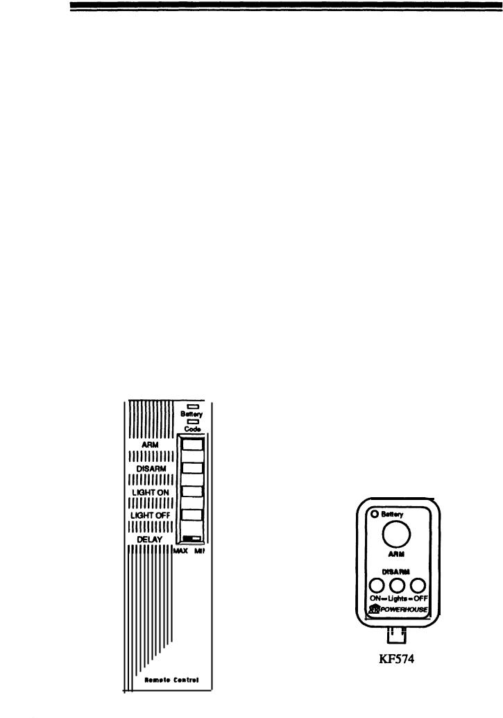
KF574 |
Remote Control |
4 |
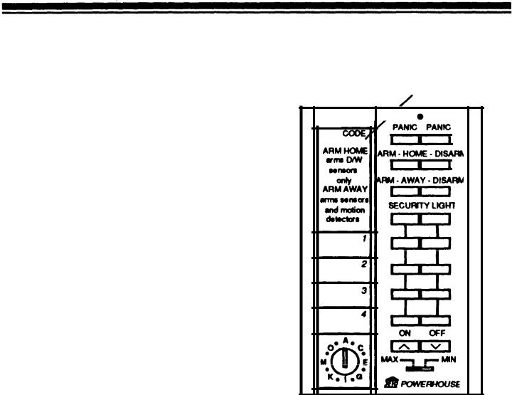
SH624 |
Remote Control |
7 |
Setting up Sensors |
8 |
|
Installing |
the Sensors |
9 |
Looping Windows Together |
10 |
|
Setting up Motion Detectors |
11 |
|
Motion Detector placement 12 |
||
Setting up Remote Modules |
13 |
|
Lamp Modules |
13 |
|
Wall Switch Modules |
13 |
|
Setting up Remote Siren |
14 |
|
Setting up Telephone Dialer |
15 |
|
Phone |
Numbers |
15 |
Voice Message |
15 |
|
Using the System |
16 |
|
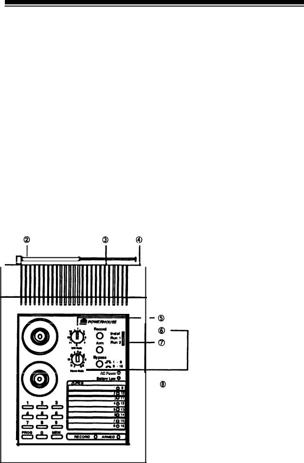
4 Console Indicators |
16 |
|
Arming and Disarming |
16 |
|
INSTANT mode |
16 |
|
DELAYED mode |
17 |
|
HOME/AWAY mode |
17 |
|
Arm without Remote Control |
18 |
|
Sounding the Panic Alarm |
18 |
|
Trouble |
Alarm |
18 |
Zones 9-16 Status Indication |
18 |
|
After an Alarm |
18 |
|
Testing the Voice message |
19 |
|
Testing the Dialer |
19 |
|
Turning Lights On and Off |
20 |
|
This is X-10 POWERHOUS TM |
E 21 |
|
Care and Maintenance |
26 |
|
Replacing |
Batteries |
27 |
Remote |
Controls |
27 |
Door/Window Sensor |
27 |
|
Motion |
Detector |
28 |
Console |
28 |
|
Troubleshooting |
29 |
|

U.L. AND F.C.C. CAUTIONS
|
|
|
|
|
|
|
|
|
|
|
|
|
|
|
|
|
|
|
|
|
|
|
FCC Caution This equipment: |
generates |
|
Important: |
|
|
||||
|
and uses radio |
frequency |
|
|
Your Security Console is FCC registered. |
|||||
|
energy, and if not |
|
|
|||||||
|
installed and use |
|
|
|
|
In order to fully comply with the FCC |
||||
|
d properly, that is, in strict |
|
|
|||||||
accordance with th |
e |
manufacturer’s |
rules, these instructions should be followed |
|||||||
instruc- |
|
|
||||||||
|
tions, ma |
y |
cause |
interference |
|
prior to installing and using the product: |
||||
|
to radio and |
|
|
|||||||
television reception. It has been type tested |
|
Connections cannot |
be made |
|||||||
|
and found to comply with the limits for re- |
|
||||||||
mote control security devices in accordance |
|
operated telephones, or to party lines. |
||||||||
|
with the specifications in subpart B of part |
|
The KC requires that any umnections |
|||||||
|
15 of FCC Rules, which ar |
designed |
eto |
to telephone lines are to use standard |
||||||
provide reasonable protection against such |
|
plugs and adaptors. |
|
|
||||||
interference |
in |
a residential |
installation. |
|
Notify the telephone company that you |
|||||
|
However, there is no guarantee that inter- |
|
||||||||
|
ference will not occur in a |
particular instal- |
|
will be connecting a Registered unit to |
||||||
|
lation. If this equipment does cause inter- |
|
the line. Give them the following infor- |
|||||||
|
ference to radio or television reception, |
|
mation regarding the Security Console: |
|||||||
|
which can be determined by unplugging the |
|
A) FCC Registered Number |
|
|
|||||
equipment, the user is encouraged to try to |
|
|
|
|||||||
correct the interference by one or more of |
|
B4SUSA-65898-AL-T |
|
|
||||||
the following measures. |
|
|
|
|
B) Ringer Equivalence |
|
|
|||
|
|
|
|
|
|
|
|
0.lB. |
|
|
Reorient antenna of the radio/TV experiencing interference.
Relocate the Console with respect to the radio/TV.
Move the Console away radio/IV.
Plug the Console into an outlet on a different branch circuit from the radio/TV experiencing the interference.
If necessary, the user should consult the dealer or manufacturer for additional suggestions.

INTRODUCTION
The PS561 Security Console is part of a Supervised Security System and is used with the following accessories, (sold separately).
Hand-held Remote Controls and Key-chain Remote Controls for arming and disarming the system and for controlling lights and appliances around the home.
Door/Window Sensors with magnetic switch and magnet.
Passive Infrared Motion Detectors.
Lamp Modules for flashing house lamps.
Wall Switch Modules for flashing indoor and outdoor lights.
Remote 110-decibel siren.
You can add Door/Window Sensors to protect up to 16 doors or windows, or add a Motion Detector to protect an area with more than one entry point. When someone opens the door or window, or enters a protected area, the Console sounds its alarm and sends signals over the house wiring to flash lights connected to X-10 Modules It can also trip an additional loud remote siren. The Console dials up to 4 preprogrammed phone numbers and plays back up to 15 seconds of pre-recorded message (in your voice). The person called can then listen in to your home to determine the nature of the problem.
You arm and disarm the system with the Remote Control and you can add up to a total of eight Remote Controls which you can give to other family members. You can also use the Remote Control to control lights and appliances around the home.
Features
Wireless Installation |
- makes it e |
to quickly make a home secure. |
|
Sixteen-Zone System |
- lets you |
tect 16 different groups of doors and/ |
|
or windows in the home. |
|
Remote Arm and Disarm |
- le |
arm the system, turn on lights, or even |
|
sound the alarm from anywhere in or |
|
around th home. |
|
Expandable Design |
- lets you a |
more Door/Window Sensors and Mo- |
|
tion Detectors to expand the system’s |
|
coverage. |
|
Fully Supervised Operation |
- |
system keeps track of the status of |
|
each Door/Window Sensor. |
|
Built-in Voice Dialer |
a friendDials |
or neighbor for help and plays back a stored message (in your voice).
X-10 POWERHOUSE Compatible - so you can add other Remote Controls to the system or even add a timer to make the home look lived-in while nobody is at home.
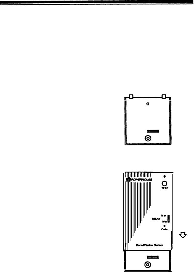
SETTING UP DOOR/ |
|
|
|
|
|
|
|
||||||||||||||||||
WINDOW SENSOR(S) |
|
|
|
|
|
|
|
||||||||||||||||||
This procedure initializes each Door/ |
|
|
|
|
|
|
|
|
|
|
|
|
|
|
|
|
|
|
|
|
|
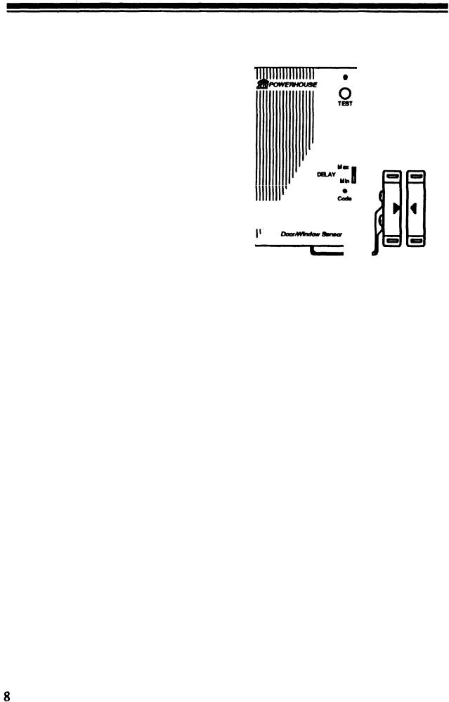
|
DW534 |
||
|
|
|
|
|
|
|
|||||||||||||||||||
Window Sensor so that the Console |
|
|
|
|
|
|
|
|
|
|
|
|
|
|
|
|
|
|
|
|
|
|
|||
|
|
|
|
|
|
|
|
|
|
|
|
|
|
|
|
|
|
|
|
|
|
|
|||
recognizes signals from the sensor. |
|
|
|
|
|
|
|
|
|
|
|
|
|
|
|
|
|
|
|
|
|
|
|
||
1. |
Install |
9a-volt alkaline battery in |
|
|
|
|
|
|
|
|
|
|
|
|
|
|
|
|
|
|
|
|
|
|
|
|
the battery compartment. |
|
|
|
|
|
|
|
|
|
|
|
|
|
|
|
|
|
|
|
|
|
|
|
|
|
|
|
|
|
|
|
|
|
|
|
|
|
|
|
|
|
|
|
|
|
|
|
|
||
2. |
Set the Console’s slide switch to |
|
|
|
|
|
|
|
|
|
|
|
|
|
|
|
|
|
|
|
|
|
|
|
|
|
|
|
|
|
|
|
|
|
|
|
|
|
|
|
|
|
|
|
|
|
|
|
|||
|
|
|
|
|
|
|
|
|
|
|
|
|
|
|
|
|
|
|
|
|
|
|
|||
|
|
|
|
|
|
|
|
|
|
|
|
|
|
|
|
|
|
|
|
|
|
|
|||
|
INSTALL. |
|
|
|
|
|
|
|
|
|
|
|
|
|
|
|
|
|
|
|
|
|
|
|
|
|
|
|
|
|
|
|
|
|
|
|
|
|
|
|
|
|
|
|
|
|
|
|
|
||
|
|
|
|
|
|
|
|
|
|
|
|
|
|
|
|
|
|
|
|
|
|
|
|
||
3. |
Press [CODE] on the sensor with a |
|
|
|
|
|
|
|
|
|
|
|
|
|
|
|
|
|
|
|
|
|
|
|
|
|
|
|
|
|
|
|
|
|
|
|
|
|
|
|
|
|
|
|
|
|
|
|
|||
|
|
|
|
|
|
|
|
|
|
|
|
|
|
|
|
|
|
|
|
|
|
|
|||
|
|
|
|
|
|
|
|
|
|
|
|
|
|
|
|
|
|
|
|
|
|
|
|||
|
pencil. |
|
|
|
|
|
|
|
|
|
|
|
|
|
|
|
|
|
|
|
|
|
|
|
|
|
|
|
|
|
|
|
|
|
|
|
|
|
|
|
|
|
|
|
|
|
|
|
|
|
|
4. |
Press [TEST). The Console’s next |
|
|
|
|
|
|
|
|
|
|
|
|
|
|
|
|
|
|
|
|
|
|
|
|
|
|
|
|
|
|
|
|
|
|
|
|
|
|
|
|
|
|
|
|
|
|
|
|||
|
unused zone indicator lights and |
|
|
|
|
|
|
|
|||||||||||||||||
|
|
|
|
|
|
|
|
||||||||||||||||||
|
|
|
|
|
|
|
|
||||||||||||||||||
|
the Console sounds a tone to indi- |
|
|
|
|
|
|
|
|||||||||||||||||
|
cate that it accepted the sensor. |
|
|
|
|
|
|
|
|||||||||||||||||
5. |
Set th |
eMIN/MAX switch to MIN |
|
|
|
|
|
|
|
||||||||||||||||
|
to protect a window. Set to Max to |
|
|
|
|
|
|
|
|||||||||||||||||
|
protect a door. |
|
|
|
|
|
|
|
|||||||||||||||||
6. |
Place one of the enclosed num- |
|
|
|
|
|
|
|
|||||||||||||||||
|
bered stickers on the sensor to |
|
|
|
|
|
|
|
|||||||||||||||||
|
show its zone number. |
|
|
|
|
|
|
|
|||||||||||||||||
7. |
To set up additional sensors, (up to |
|
|
|
|
|
|
|
|||||||||||||||||
|
16) repeat Steps l-6. |
|
|
|
|
|
|
|
|||||||||||||||||
When you set the Console back to RUN it plays back the stored message and the BUS LightY stays on for 15 seconds.
Note: You can install any combination of Door/Window Sensor (DW534)s and Motion Detectors (SP544) up to a total of sixteen zones. For example: you coul installd twelve DW534 sand, four SP544s, or any other combination up to total of sixteen zones.
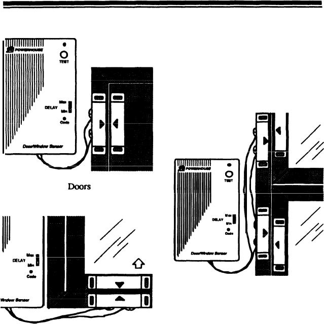
Windows
Note: For sliding windows it is best to mount the magnet and switch at the bottom of the window with the arrows facing each other. This way the magnet wiII make a “clean break” from the switch when the window is opened. If you want to mount them on the side of the window (so that the magnet “slides past” the switch) you should offset them slightly so that the arrows DO NOT line up, as shown in the diagram to the right.
10
To protect more than one door or window fkom a single sensor
Use N.C. (Normally Closed) type magnetic switches and Ioop them in series from one door or window to the next (using any suitable wire). Then connect both ends of the loop to the sensor. See below.
Note: N.C. means Normally Closed. This type of magnetic switch is supplied with the sensors. These switches are normally closed when the door or window is closed, and open when the magnet is moved away. This type of magnetic switch is used so that if the wire between the magnetic switch and the Door/Window Sensor is cut, the alarm trips. If you want to connect more than one magnetic switch to a sensor yo willu need to connect them in series (not in parallel).
You can use Normally Open (N.O.) magnetic switches if you want to connect them in parallel but the alarm will not trip if someone cuts the wire between the switch and the sensor.
 Loading...