

Page 1

This Manual is Bookmarked
Operating Instructions and Parts Manual
Belt and Disc Sander
Model 41002
WMH TOOL GROUP
2420 Vantage Drive
Elgin, Illinois 60123 Part No. M-41002
Ph.: 800-274-6848 Revision A 10/05
www.wmhtoolgroup.com Copyright © WMH Tool Group
Page 2

This manual has been prepared for the owner and operators of a Wilton 41002 Belt/Disc Sander. Its
purpose, aside f rom machine oper ation, is to promot e safety using acc epted operati ng and maint enance
procedures. To o btain m aximum lif e and effi ciency fr om your sander and t o aid in usi ng it saf ely, please
read this manual thoroughly and follow the instruc tions carefully.
Warranty and Service
WMH Tool Gr oup warrants ever y product it sell s. If one of our tools needs s ervice or repai r, one of our
Authorized S ervic e Center located throughout the United States can provide quick servi ce or information.
In most cases, a W MH Tool Group Servi ce Center can assist i n authori zing repai r work, obtai ning part s,
or perform routine or major maintenance repai r on your Wilt on product.
For the name of an Aut horized Service Cent er in your area, pl ease call 1-800-274-6848, or vi sit our web
site at www.wmhtoolgroup.com
More Information
Remember, WMH Tool Group i s consistently adding new products to the li ne. For complete, up-to-dat e
product information, check with your local WMH Tool Group distributor, or visit our web site at
www.wmhtoolgroup.com
WMH Tool Group Warranty
WMH Tool Group makes every effort to assure that it s products meet high quality and durability standards
and warrants to the original retail consumer/purchaser of our products that each product be free from
defects in mat erials and workmanship as foll ows: 1 YEAR LI MITED WARRANTY ON ALL PRODUCTS
UNLESS SPECIFIED OTHERWISE. This Warranty does not apply to defects due directly or i ndirectly to
misuse, abuse, negl igence or acc idents, norm al wear-and-tear , repair or alterati ons outside our f aciliti es,
or to a lack of maintenanc e.
WMH TOOL GROUP LIMITS ALL IMPLIED WARRANTIES TO THE PERIOD SPECIFIED ABOVE,
BEGINNING FROM THE DATE THE PRODUCT WAS PURCHASED AT RETAIL. EXCEPT AS STATED
HEREIN, ANY IMPLIED WARRANTIES OR MERCHANTABILITY AND FITNESS ARE EXCLUDED.
SOME STATES DO NOT ALLOW LIMITATIONS ON HOW LONG THE IMPLIED WARRANTY LASTS,
SO THE ABOVE LIMITATION MAY NOT APPLY TO YOU. IN NO EVENT SHALL WMH TOOL GROUP
BE LIABLE FOR DEATH, INJURIES TO PERSONS OR PROPERTY, OR FOR INCIDENTAL,
CONTINGENT, SPECIAL, OR CONSEQUENTIAL DAMAGES ARISING FROM THE USE OF OUR
PRODUCTS. SOME STATES DO NOT ALLOW THE EXCLUSION OR LIMITATION OF INCIDENTAL
OR CONSEQUENTIAL DAMAGES, SO THE ABOVE LIMITATION OR EXCLUSION MAY NOT APPLY
TO YOU.
To take advantage of this warranty, the product or part must be returned for examination, postage
prepaid, to an Authorized Service Center designated by our office. Proof of purchase date and an
explanati on of the complaint m ust accompany the merchandi se. If our inspecti on discloses a defec t, we
will either repair or replace the produc t at our discret ion, or r efund t he purchase pri ce if we cannot readi l y
and quickly provide a repai r or replac ement. We will return the repai red product or replacem ent at WMH
Tool Group’s ex pense, but if it is determ ined there i s no defect, or that the def ect resulted f rom causes
not within the scope of WMH Tool Group’s warranty, then the user must bear the cost of storing and
returning t he product . This warranty gives you specifi c legal ri ghts; you m ay also have ot her ri ghts, which
vary from state t o state.
WMH Tool Group sells through distributor s only. Members of the WMH Tool Group reserve the right to
effect at any time, wit hout prior notice, alter ations to parts, fittings and accessory equi pment, which they
may deem necessary for any reason whatsoever.
2
Page 3

Table of Contents
Warranty and Servic e ..............................................................................................................................2
Table of Contents....................................................................................................................................3
Warning...................................................................................................................................................4
Introduction..............................................................................................................................................6
Specifications..........................................................................................................................................6
Features and Terminology....................................................................................................................... 7
Unpacking............................................................................................................................................... 8
Contents of the Shipping Container......................................................................................................8
Assembly.................................................................................................................................................9
Installing Belt Table..............................................................................................................................9
Installing Dust Chute............................................................................................................................9
Installing Disc Table...........................................................................................................................10
Installing Miter Gauge.........................................................................................................................10
Installing Tension Handle ...................................................................................................................10
Grounding Instructions...........................................................................................................................11
115 Volt Operati on .............................................................................................................................11
Extension Cords.................................................................................................................................12
Adjustments...........................................................................................................................................12
Tilting th e Be lt Ta b le...........................................................................................................................12
Tilting th e Dis c Ta b le..........................................................................................................................12
Use of the Miter Gauge ......................................................................................................................13
Belt Platen..........................................................................................................................................13
Abras i ve Bel t Re p lac ement................................................................................................................ 14
Tracking the Abrasive Belt..................................................................................................................14
Abrasive Disc Replacem ent................................................................................................................15
Aluminum Disc Removal ....................................................................................................................15
Operation...............................................................................................................................................16
Starting and Stopping the Sander.......................................................................................................16
Belt and Disc Movement.....................................................................................................................16
Typical Op e ra tions.............................................................................................................................16
Maintenance..........................................................................................................................................18
Replacement Parts................................................................................................................................18
Troubleshooting.....................................................................................................................................19
2x42x8 Belt and Disc Sander..............................................................................................................20
Parts List for 2x42x8 Belt and Disc Sander.........................................................................................21
3
Page 4

Warning
1. Read and understand the entire owners manual before attempting assembly or operation.
2. Read and understand the warnings po sted on the m achine and i n thi s manual. Failur e to comply wit h
all of these warnings m ay cause seriou s i njury.
3. Replace the warning labels if they become obscured or removed.
4. This sander is designed and int ended for use by proper ly t rained and experi enced personnel onl y. If
you are not f amiliar wit h the proper and safe operati on of a sander, do not use unt il proper t raining
and knowledge have been obtained.
5. Do not use this sander f or other t han its i ntended use. If used f or ot her purposes, W MH Tool Group
disclaim s any real or i mplied warrant y and h olds itsel f harml ess from any injury t hat may r esult f rom
that use.
6. Always wear appr oved safety glasses/face shields while u si ng this sander. Everyday ey eglasses only
have impact resistant lenses; they are not safet y glasses.
7. Before operati ng this sander, rem ove tie, ri ngs, watches and other j ewelry, and r oll sleeves up past
the elbows. Rem ove all l oose clothing and confine l ong hair . Non-slip footwear or anti-skid floor strips
are recommended. Do not wear gloves.
8. Wear ear protector s (plugs or muffs) during extended peri ods of operation.
9. Some dust created by power sanding, sawing, grinding, drilling and other construction activities
contain chemi c als known to the S tate of California to cause cancer, birth defects or other r epr oductive
harm. Some exampl es of these chemicals are:
• Lead from lead based paint.
• Crystalli ne sil ic a from bricks, cement and other m asonry pr oduc ts.
• Arsenic and chromium from chemically treated lumber .
Your risk of exposure varies, depending on how often you do this type of work. To reduce your
exposure to these chemicals, work in a well-ventilated area and work with approved safety
equipment, such as face or dust masks that are specifically designed to filter out microscopic
particles.
10. Do not operate this machi ne while tired or under the influence of drugs, al c ohol or any medication.
11. M ak e c er tain the switch is in the OFF position before connecting the machine to the power supply.
12. M ak e c er tain the machine is properly grounded.
13. M ak e all machine adjustments or maintenance with the machine unplugged f r om the power source.
14. Remove adjusting keys and wrenches. Form a habit of checking to see that keys and adjusting
wrenches are removed from the machine before turning it on.
15. Keep safety guards in place at all times when the machi ne is in use. If removed for maintenance
purposes, use extreme caution and replace the guards immediately.
16. If there is a tendency f or the machine to ti p over or move dur ing operation, such as when sanding
long or heavy boards, the machine must be securely fastened to a supporting surface.
17. Check damaged parts. Before further use of the machine, a guard or other part that is damaged
should be carefully checked to determine that it will operate properly and perform its intended
function. Check for alignment of moving part s, binding of moving parts, br eakage of parts, mounting
and any other condi ti ons that m ay affect its operati on. A guard or ot her part that i s damaged shoul d
be properly repaired or replaced.
18. P r ov ide for adequate space surroundi ng work area and non-glare, ov er head lighting.
19. K eep the floor around the machi ne cl ean and free of scrap material, oil and grease.
20. K eep v isitors a safe distance from the work area. Keep children away.
4
Page 5

blahblahblah
21. M ak e y our workshop child proof with padloc ks, master switches or by removing starter keys.
22. Giv e your work undivi ded attention. Looking ar ound, carryi ng on a conversation and “ horse-play” ar e
careless acts that can r esul t in serious injury.
23. Maint ain a balanced stanc e at all tim es so that you do not fall or lean against t he abrasiv es or other
moving part s. Do not over r eac h or use exc essive force to perform any machine oper ation.
24. Use the ri ght t ool at the corr ect speed and f eed r ate. Do not forc e a tool or att achment to do a job for
which it was not designed. T he ri ght tool will do the job better and safer.
25. Make sure the abrasive belt is running in the proper direction. When disc sanding, place the
workpiece against t he downward rot ating part of the abrasive disc.
26. Thi s machine can be used f or sanding wood or met al products. Ho wever , combini ng wood dust an d
metal fil ings can create a fire haz ard. Make sure your dust col lector is fr ee of wood dust depo sits
before processing m etal products.
27. Use recom mended accessories; improper accessories m ay be hazar dous.
28. M aintain tools with care. F ollow instructions for lubric ating t he m ac hine and changing accessories.
29. Abrasiv e discs m ust be stored in a cont roll ed environm ent. Relativ e humidity should be 35% t o 50%
and the temperature should be between 60° and 80° Fahrenheit. Failure to do this could cause
premature disc failure.
30. Examine t he face of t he abrasive disc or belt caref ully. Excessive sanding that wear s down to the
backing materi al can t ear the disc/ belt. Never use an abrasiv e whic h shows backi ng, ni cks or cuts on
the surface or edge, or dam age due to creasing or poor handling.
31. Turn off the mac hine before cl eaning. Use a brush or compressed air to rem ov e c hips or debris — do
not use your hands.
32. Never leave the machine r unning unattended. Turn the power off and do not leav e the mac hine until it
comes to a complete stop.
33. Do not use the sander in wet or damp locations.
34. Remove loose items and unnecessary work pieces from the area bef or e starting the machine.
Familiarize you rself with the following safety no tices used in this manual:
This means that if precautions are not heeded, it may result i n mi nor i njur y and/or
possible machine damage.
This means that if precautions are not heeded, it may result i n serious injury or possibly
even death.
- - SAVE THESE INSTRUCTIONS - -
5
Page 6

Introduction
This manual is provided by W MH Tool Group cov ering the safe oper ation and mai ntenance procedure s
for a Wilton 2x42x8 Belt and Disc Sander. This manual contains instructions on installation, safety
precautions, gener al oper ati ng procedur es, mai ntenance i nstructi ons and parts breakdo wn. Thi s mac hine
has been designed and con structed t o provide year s of troubl e free operation if used in accordance wi th
instructi ons set forth i n this manual . If there are any questions or comm ents, please contact either your
local supplier or WMH Tool Group. WMH Tool Group can also be reached at our web site:
www.wmhtoolgroup.com.
Specifications
Stock Number..................................................................................................................................41002
Belt Size (in.)(LxW).......................................................................................................................... 42 x 2
Disc Size (in.)...........................................................................................................................8 diameter
Motor.............................................................................................................................3/4HP, 1Ph, 115V
Belt Tabl e Size (in.)(LxW)................................................................................................................ 10 x 6
Disc Table Size (in.)(LxW) ...................................................................................................10-3/4 x 7-1/2
Table Tilt (deg.) ..............................................................................................................................0 to 45
Dust Chutes (i n.)...................................................................................................... two @ 1-1/2 diameter
Overall Size (in.)(WxDxH)...........................................................................................20-1/2 x 22-3/4 x 20
Approximate Net Weight (lbs.) ...............................................................................................................58
Approximate Shipping Weight (lbs.).......................................................................................................64
The above specifications were current at the tim e this manual was publi shed, but because of our policy of
continuous im provement, WMH Tool Group reserv es the right to change specif ications at any tim e and
without pri or notic e, without incurring obligations.
6
Page 7
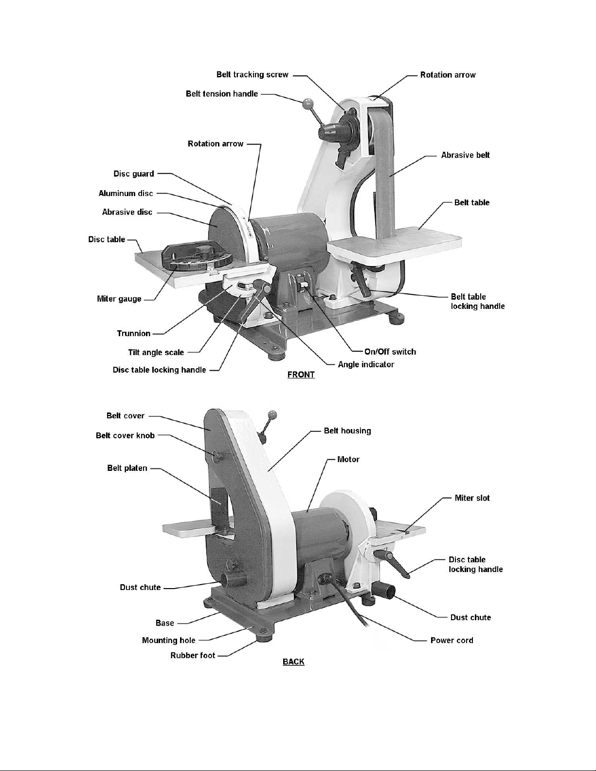
Features and Terminology
7
Page 8
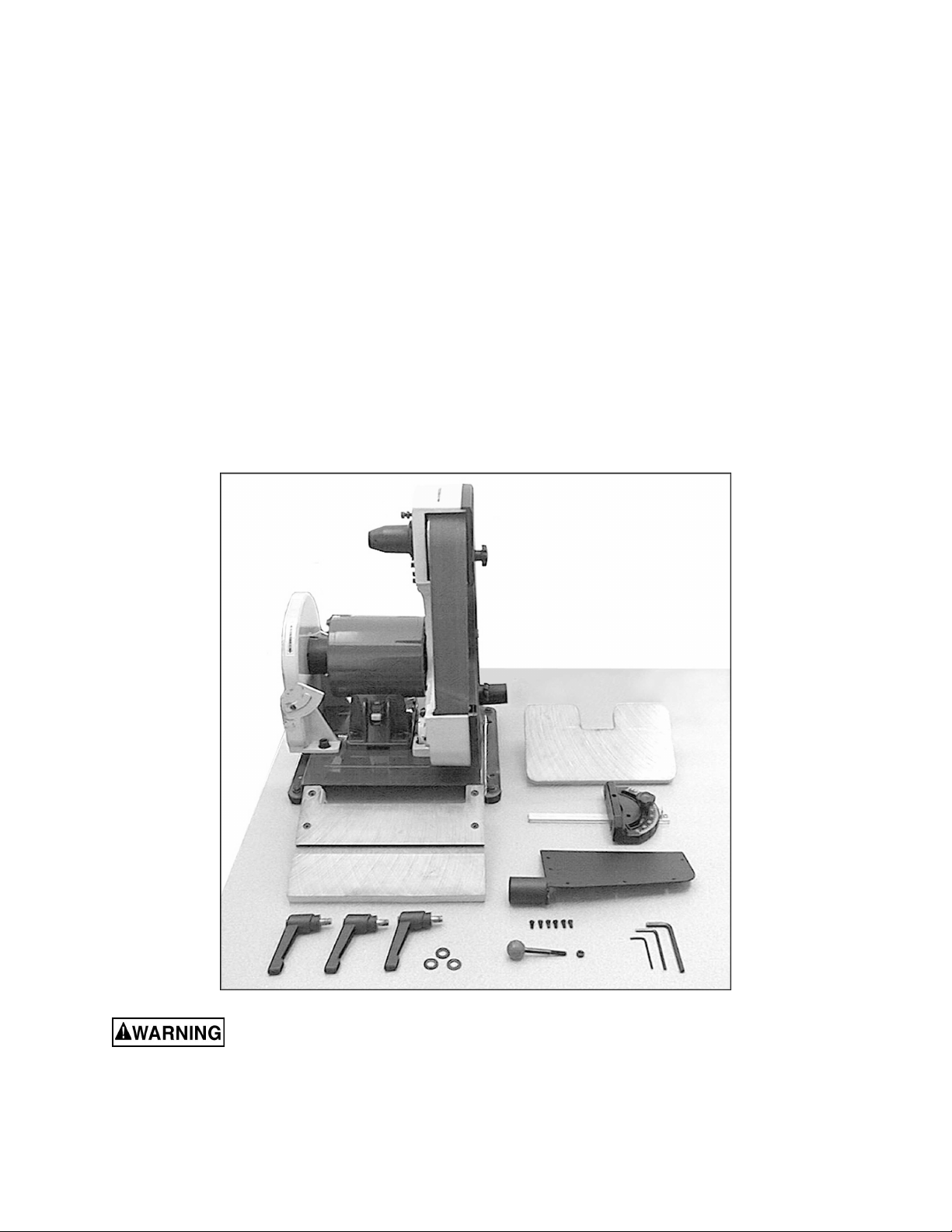
Unpacking
Open shipping cont ainer and check f or shipping
damage. Report any damage immediately to
your distributor and shipping agent. Do not
discard any shippi ng material until t he sander is
assembled and running properly.
Compare the cont ent s of y our cont ainer wit h the
following parts list to make sure all parts are
intact. Mi ssing parts, if any, should be reported
to your distributor. Read the instruction manual
thoroughly for assembly, maintenance and
safety instructions.
Contents of the Shipping Co ntainer
1 Belt and Disc Sander
1 Belt Table
1 Disc Table with trunnions
1 Miter Gauge
1 Dust Chute
6 Phillips Pan Hd. Machine Screws, 3/16x3/8”
3 Handles
3 Flat Washers, 3/8”
1 Tension Handle
1 Hex Nut, 1/4”
3 Hex Wrenches, 3, 4 and 6mm
1 Owner's Manual
1 Warranty Card
Read and understand the entire contents of this manual before attempting set-up
or operation! Failure t o co mpl y may cause seri ou s injury.
8
Page 9

Assembly
Tools needed for assembly:
• 10mm open-end wrench
• Cross-point (Phillips) screwdriver
• Combination square, or similar angle
measuring devic e.
Sander must be unplugged
from power source during assembl y.
Remove the protective coating from the surf ac es
of the sander and from any loose parts. This
coating may be removed with a soft cloth
moistened with kerosene (do not use acetone,
gasoline or lacquer thinner for this purpose).
After cleaning, cover the table surfaces with a
good quality paste wax.
Leave enough space aroun d the sander f or l ong
workpieces and for gener al maintenance.
If needed, the sander can be bol t ed to a t abl e or
workbench using the holes in the base. If the
sander has a tendency to walk or slide during
operation, it must be bolted to a supporting
surface.
Installing Belt Table
1. Unscrew the stud. See Figur e 1.
2. Position the brac k et of the belt table over the
holes in the ca sting as sh own, and re-i nstall
the stud into its hole.
3. Place a flat washer onto a handle, and i nsert
the handle through the table bracket and
into the hol e. Screw the handle all the way
into the hole.
NOTE: The handle i s spring loaded; screw
the handle in by rotati ng cloc kwise, then pul l
outward on the handle. Rotate the handle
back to position, then release it, making sure
it seats itself upon the pin. Continue the
process until the handle is ti ghtened in the
hole.
Installing Dust Chute
The sander has two 1- 1/2” diameter dust chutes.
The dust chute for the belt is locat ed on the belt
cover. The dust chute for the disc should be
install ed as shown in Figure 2, using the six (6)
pan head machine screws that ar e pr ov ided.
Figure 1
The dust chutes can be connect ed to a vacuum
system to collect dust particles.
Figure 2
9
Page 10

Installing Disc Table
1. Position the disc table at an angl e, as shown
in Figure 3, and sli de the table on so that the
trunnion slots fit over the raised tracks on
the disc guard.
2. Install a flat washer onto each of the two
remaini ng handles. Insert the handl e into the
holes through the left and right trunnions.
See Figure 4.
3. The gap between the sanding di sc and the
disc table sho uld be a m aximum of 1/ 16”. If
it is larger than this, loosen the two socket
head cap screws on the disc guard (one is
shown in Fi gure 4) and sli de the disc guard
to achieve this gap m easurement.
4. When finished, tighten the two socket head
cap screws securely.
Figure 3
Installing Miter Gauge
Insert the miter gauge bar into one end of the
miter slot in the disc table. See Figure 5.
The miter gauge can be used in eit her directi on
in the slot to achieve the most effective
positioning of the workpiece against the abrasive
disc.
Installing Tension Handle
1. Place the 1/4” hex nut onto the threads of
the tension handle.
2. Screw the tension handle into the hole on
the hub, then ti ght en the hex nut against the
hub. See Figure 6.
Figure 4
Figure 5
Figure 6
10
Page 11

Grounding Instructions
This machine must be
grounde d while in use to prot e c t t he ope r a tor
from electric shock.
In the event of a malfunction or breakdown,
grounding prov i des a path of least resistanc e f or
electric current to reduce the risk of electric
shock. This tool is equipped with an electric cord
having an equipment-groundi ng c onduc tor and a
grounding plug. The plug m ust be inserted into a
matching receptacle that is properly installed
and grounded in acc orda nce with al l l ocal codes
and ordinances.
Do not modify the plug provi ded. If it will not fit
the outlet , have the proper outlet i nstalled by a
qualified elec trician.
Improper connection of the equipmentgrounding conductor can result in a risk of
electric shock. The conductor, with insulation
having an outer surface that is green with or
without yellow stripes, is the equipmentgrounding conductor . If repair or replacement of
the electric cord or plug is necessary, do not
connect the equi pment-grounding conductor to a
live terminal.
Check with a qualified electrician or service
personnel if the grounding instructions are not
completely understood, or if in doubt as to
whether the tool is properl y grounded. Use onl y
three wire ex tension cords that have three-prong
grounding plugs and t hree-pole recept acles that
accept the tool’s plug.
115 Volt Operation
As received from the factory, your sander is
ready to run at 115 volt operation. This sander is
intended for use on a circuit that has an outlet
and a plug that looks like the one illustrated in
Figure 7.
A temporary adapt er, like the adapter i n Figure
8, may be used to connect this plug to a twopole receptacle, as shown in Figure 8, if a
properly grounded outlet is not available. The
temporary adapter should only be used until a
properly grounded outlet can be installed by a
qualified electrician. This adapter is not
applicable in Canada. The green colored rigid
ear, lug, or tab, extending from the adapter,
must be connected t o a permanent ground such
as a properly gr ounded outlet box, as shown in
Figure 8.
Figure 7
Figure 8
11
Page 12

Extens ion Cords
Use proper ext ension cor ds. Make sur e the cor d
rating is suitable for the amperage of the
machine’s mot or. An undersized cord will cause
a drop in line voltage r esulting in loss of power
and overheating.
Use the chart in F igure 9 as a general gui de in
choosing the correc t size cord. The smaller the
gauge number, the heavier the cord.
Recommended Gauges (AWG ) of Extension Cords
Extension Cord Length *
25
50
75
100
150
Amps
< 5 16 16 16 14 12 12
5 to 8 16 16 14 12 10 NR
8 to 12 14 14 12 10 NR NR
feet
feet
feet
feet
feet
200
feet
Adjustments
Tilting the Belt Table
The belt table til ts from zero ( horizont al) down to
45°.
1. Loosen the handle and adjust t he table into
desired positi on.
2. Check the angle with a machinist’s
protractor or similar measuring device that
has the required angle. Figure 10 shows a
square being used to confirm the zero, or
horizontal, positi on. Place the square flat on
the table and agai nst the bel t. Push against
the belt until the square is against the
platen.
3. Make any adjustment s to the table angle as
necessary until it is square with the belt.
4. Tighten the handle securely.
To avoid trapping the
workpiece or fingers between the table and
abrasive belt, the table edge should be
positioned a maximum of 1/16” from the
abrasive belt.
Tilting the Disc Table
The disc table tilts from zero (horiz ontal) down to
45°.
12 to 15 12 12 10 10 NR NR
15 to 20 10 10 10 NR NR NR
21 to 30 10 NR NR NR NR NR
*based on li miting th e lin e vol tage drop to 5V at 15 0% of th e
rated amp eres.
NR: Not Re commende d.
Figure 9
Figure 10
1. Loosen both handles and adjust the table
until the indicator lines up with the desired
angle on the scale. It is a good idea to
confirm this angle using your angle
measuring devi ce placed flat upon the table
and against the abrasive disc.
2. Figure 11 shows a square being used to
confirm the z er o, or horizontal position of the
disc table.
3. Make any necessary adjustments to the
table angle. If the table is square with the
disc but the angle indicator needs slight
adjustment, loosen the screw on the
indicator and shift the indicator as needed.
Re-tighten the screw.
Figure 11
12
Page 13

4. Tighten both handl es securely.
To avoid trapping the
workpiece or fingers between the table and
abrasive disc, the table edge should be
positioned a maximum of 1/16” from the
abrasive disc.
Use of the Miter Gauge
The miter gauge is used to sand accurate
angles on workpieces. When using the miter
gauge on the hori zontal table position, you c an
sand a single angl e. By tilt ing the disc t able and
using the miter gauge in combination with the
table tilted, it is possible to sand compound
angles as well.
The miter gauge rotates to 30° for bevel
sanding. Loosen t he knob and rot ate the gauge
body until the pointer li nes up with the desired
angle on the scale.
Use a square to c onfirm that the miter gauge i s
set at 90° (perpendi c ular to the disc). See Figure
12. If slight adjustment is needed:
1. Loosen the knob.
2. Adj ust the miter gauge body unti l it is flush
with the square, and t he square i s f lush with
the disc.
3. Tighten the knob.
4. Loosen the screw on the pointer and adjust
the pointer until it aligns with 90° on the
scale.
5. Tighten the screw on the poi nter.
Figure 12
Belt Platen
The belt platen (Figure 13) is used to properly
support the workpi ece whi le sandi ng. T he plat en
is constructed of heavy steel to provide
adequate support.
The platen should be adjusted so it is almost
touching the back of the abrasive belt. Loosen
the socket head cap screw and adju st the pl aten
to the desired position. Tighten the screw to
secure the platen.
The platen can be r emoved f or operations such
as stripping, c ontour sanding, polishing or ot her
special operations. To remove the platen,
remove the socket head c ap screw and washer.
Be sure to re-install the platen to perform
operations where support of the belt is required.
Figure 13
13
Page 14

Abrasive Belt Replacement
1. Unplug the Sander from the power source.
2. Unscre w and remov e the two knobs on the
belt cover.
3. Remove the belt cover.
4. Rotate the tension handle (Figure 6) to
loosen the belt, and r em ov e the old belt from
around the wheels.
5. Install the new belt around the wheels.
IMPORTANT: Some sanding belts have a
directional arrow printed on the i nsi de of t he belt.
In these cases, t he belt m ust be install ed so the
directional arrow is in the same directi on that the
machine is running. Refer to the rotation arrow
on top of the belt cover.
6. Install the belt cover and the two knobs.
7. Start the sander and check t he belt tracking
before sanding operations (See “Tracking
the Abrasive Belt”).
Tracking the Abrasive Belt
“Tracking” refers to the manner in which the
abrasive bel t is positioned on the wheel s during
operation. The belt should remain in vertical
position wit hout shifti ng to one side or the other
of the wheel. If any shifting occurs, the belt
needs to be tracked properly, as follows:
1. Disconnect sander from power source.
2. Remove the side cover , and make sure the
belt is pl aced evenly over the cent er of the
wheels. Loosen the tension and re-position
the belt if necessary. Re-install the side
cover.
3. Move the belt by r otating the disc with your
hand (do not turn on the power yet).
Observe the movement of the belt on the top
wheel.
4. If the belt slips to one side or the other,
loosen the hex nut (Fi gure 14) with a 10m m
open-end wrench.
5. Rotate t he tracki ng screw (Fi gure 14) with a
5mm hex wrench. If the belt is sliding toward
the right, rotate the screw clockwise. If the
belt is sliding toward the left, rotate the
screw countercl oc k wise.
6. Continue t his procedure in sm all inc rements
until the belt is tracking properly when
moved by hand.
7. Re-connect t he sander to power, and cycle
the on/off switc h quic kly t o double c heck t he
tracking.
Figure 14
14
Page 15

8. Make further adj ustm ents as needed.
9. Tighten the hex nut to secur e the setting.
Abrasive Disc Replacement
1. Unplug the sander from the power source.
2. Remove the dust cover and the disc table.
To remove the disc table, remove the
handles then til t the disc table upward while
pulling it away f r om the disc.
3. Peel off the old abrasive disc.
4. Thoroughl y clean the aluminum disc surface
using naptha or a similar non-flammable
solvent that will dr y film-free.
5. Pull the protective backing half-way off the
new abrasive disc.
6. Carefully posi tion the new abra sive disc so it
is centered accur ately on the aluminum disc.
7. W hen accurately centered, r emove the rest
of the protective backing and press the
abrasive disc firmly against the aluminum
disc so complete adhesive contact is made.
8. Re-install dust c over and table.
9. Reconnect sander to power source.
Aluminum Disc Removal
The aluminum disc can be easily removed if
needed; for example, to facilitate cleaning the
aluminum di sc when replac ing abrasive discs.
1. Unplug sander fr om the power source.
2. Remove the disc tabl e and the dust chute.
3. Rotate the disc until the set screw is
accessible through the opening behind the
disc guard. See Fi gure 15. Y ou may need t o
loosen the socket head cap screws (see
Figure 4) on t he gu ard an d shi ft it for ward in
order to clear t he set screw.
4. Loosen the set screw with a 3mm hex
wrench, and pull the aluminum disc off the
motor shaft.
5. When re-m ounting the aluminum disc, make
sure the key is properly seated in the
keyway on the m otor shaft. Tighten t he set
screw firmly when the disc has been
mounted.
Figure 15
15
Page 16

Operation
This sander is intended for dry sanding of
metals. Do not use lubricant s.
Do not sand or polish
magnesium; it may create a fire hazard. Also ,
do not sand very small or very thin
workpieces that can no t be safely controlled.
Starting and Stopping the Sander
The on/off switch is located on the side of the
motor housing. Move the switch upward to the
ON positi on to start the sander. Move the switch
downward to the OFF position to stop the
sander.
When the sander is not being used, the switch
can be locked in OFF position to prevent
unauthorized use. Pull out the locking tab and
store in a safe pl ace. See Figure 16. The switch
will not operat e with the locking tab removed.
To use the sander, re-i nsert the locking tab.
Belt and Disc Movement
When the machine is turned on, the abrasive
belt should be moving downward and the disc
rotating clockwise. The motor is wired at the
factory for correct rotation.
The workpiece should not contact the disc or
belt during start-up. Before sanding, always
allow the motor to come up to operati ng speed,
then observe t he disc for wobble, runout, or any
unbalanced condit i on. If the disc i s not operat ing
accurately and smoothly, stop the motor and
make repairs before atempting any sanding
operations.
Always sand on the side of the abrasive disc
that rotates downward. Sanding on the upward
rotation side can cause the workpiece to catch
and fly out of your hands.
The table must be a maximum of 1/16” away
from the abrasive disc or belt.
Typical Operations
When sanding a compound angle you should
check the accur acy of your setup by sanding a
piece of scrap material before doing any finish
sanding on the actual workpiece.
Figure 16
Figure 17 demonstrates a basic method of
operation using the miter gauge and disc table:
1. Set the angle you wish to sand using the
scale on the miter gauge.
Figure 17
16
Page 17

2. Tighten the miter gauge securely so the
miter ref erence angl e will not shif t while y ou
are sanding.
3. Place the workpiece against the miter
reference surface and slide it along the miter
reference surface and into the sanding disc.
The following are just some of the many
operations that can be performed with your
Wilton Sander.
• Sharpening a wood chisel on the sanding
belt using a bl ock of wood. Use the bloc k of
wood to support the chisel and provide
clearance for the chisel handle. See Figure
18. Sand a bevel in the block of wood in
order to position the block as close as
possible to the sanding belt and clamp the
block to the table.
• A cold chi sel can also be sharpened on the
belt table with the table tilted.
• Sanding alumi num on the disc unit with the
table tilted and using the miter gauge as a
guide. See Figure 19.
Figure 18
• Sanding outside curv es on the belt unit with
the platen removed. See Figure 20.
• Polishing using a felt belt (not provided) in
place of the sanding belt. NOTE: Most
polishing oper ations are performed with the
platen remov ed.
• Sanding in t ight ar eas with the sanding bel t.
See Figure 21.
Figure 20
Figure 19
Figure 21
17
Page 18

Maintenance
Before performing any
maintenance on t he machine, disconnect it from
the electrical supply by pulling out the plug or
switching off the main switc h. Fail ure to comply
may cause serious injur y .
Keep the table surfaces clean and f ree of rust. If
rust appears on the tables, use 000 steel wool
with a paste mixt ure of household amm onia and
good commercial detergent (or use a
commercial rust remover available from most
hardware stores.)
A light coat of paste wax on the tables will help
protect them from tarnish and reduce friction
between table and workpiece. NOTE: Do not get
paste wax on the abrasive belt or disc.
Check all fasteners f or tightness.
Inspect the power cord; if worn, cut , or damaged
in any way, have it repl ac ed immediately.
Inspect the abrasive belt and disc. If either is
worn, replace it.
Occasionally remove the belt cover and brush
out any shavings or debris from around the
wheels.
Lubrication
All of the ball bearings are packed with grease
and sealed at the factory. They require no
further lubrication.
Replacement Parts
Replacement par ts are listed on pages 20-22. To order part s or r eac h our serv ice department , call 1-800274-6848 between 7:30 a.m . and 6:00 p.m. (CST), Monday through Friday . Having the Model Number
and Serial Number of your machine available when you call will allow us to serve you quickly and
accurately.
18
Page 19

Troubleshooting
Trouble Probable Cause Remedy
Not connected to power source. Connect to power source.
Determine r eason for blown fuse/
Branch circuit fuse is blown or the
circuit breaker is tr ipped.
Sander will not star t.
tripped break er ( such as short circuit
or motor overload) . Correct reason for
fault. Repl ac e fuse/ reset ci rcuit
breaker.
Voltage is too low.
Switch is defective. Replace switch.
Motor failure. Replace motor.
Motor stalls easily. Low voltage.
Abrasive disc
separates fr om
al uminum dis c.
Abrasive belt will not
track correctly.
Improper bond.
Belt not centered on wheels. Readjust track ing. See page 14.
Belt stretched unevenly. Replace abrasive belt.
Belt is jointed impr oper ly.
Wheel is worn. Replace affected wheel .
Worn bearings.
Check power source f or pr oper
voltage.
Check power source f or pr oper
voltage and correct if necessary.
Clean residual adhesive from
aluminum di sc, and re-apply
adhesive- bac ked abrasive disc.
Check the belt for an irr egular seam
or shape. Replace if needed.
Check all the beari ngs for ex c essive
heat or loose shaft s. Replac e if
necessary.
Abrasive belt slips or
stalls when pressure
is applied.
Frequent
replacement of
abrasive belt or disc.
Abrasive belt t ensi on inadequate;
spring in tensi on m ec hanism is worn.
Excessive pressure being applied to
platen.
Too much pressure being appl ied to
workpiece.
Full width of belt or di sc not bei ng
used.
Incorrect abrasive material or grit
size.
Replace spring.
Reduce pressure on abrasive belt
(and platen).
Allow the belt to do the cutti ng.
Excessive pressure only dulls the grit
and removes it from the cloth.
Stroke across abrasive belt using full
width of belt surfac e.
Check with your abrasives supplier for
recommendations on the type and
coarseness of t he abrasive required
for your parti c ular workpieces.
19
Page 20

2x42x8 Belt and Disc Sander
20
Page 21

Parts List for 2x42x8 Belt and Disc Sander
Index No. Part No. Description Size Qty
1...............41002-01................. Base.................................................................. ...................................1
2...............TS-0680042............Flat Washer....................................................... 3/8”.............................2
3...............TS-1551031............Lock Wash e r......................................................M5..............................4
4...............TS-1515041............Socket Head Cap Screw.................................... M8x30........................4
5...............TS-0050021............Hex Cap Screw..................................................1/4-20x5/8”.................4
6...............TS-0720081............Lock Wash e r......................................................5/1 6 ”...........................4
7...............41002-07................. Rubber Foot ...................................................... ...................................4
8...............TS-0680021............Flat Washer....................................................... 1/4”.............................4
9...............TS-0570011............Hex Nut............................................................. 1/4”-20........................4
10.............TS-1525021............Socket Set Screw..............................................M10x12......................1
11.............41002-11................. Capacitor Cap.................................................... ...................................1
12.............41002-12................. Capacitor........................................................... 150 UF, 125VAC.........1
13.............HBS814GH-166-5... Cr os s Head Flat Screw......................................10-24x3/8”..................6
14.............41002-14................. Capacitor Clamp ............................................... ...................................1
15.............TS-0570011............Hex Nut............................................................. 1/4”-20........................4
16.............TS-0720071............Lock Wash e r......................................................1/4”.............................4
17.............TS-1504051............Socket Head Cap Screw .................................... M8x25........................4
18.............41002-18................. Strain Relief Plate.............................................. ...................................1
19.............41002-19................. Strain Relief.......................................................6N-4...........................1
20.............41002-20................. Line Cord........................................................... ...................................1
21.............41002-21................. Relay................................................................. ...................................1
22.............41002-22................. Strain Relief Bushing......................................... ...................................1
23.............41002-23................. Self Tapping Screw............................................10-24X3/8”..................2
24.............41002-24................. Motor Housing Base.......................................... ...................................1
24A...........41002-24A .............. Motor Assembly................................................. 115V, 1Ph...................1
25.............41002-25................. Switch with Key ................................................. ...................................1
26.............41002-26................. Copper Washer ................................................. ...................................1
27.............TS-081C022............ Phillips Pan Head Machine Screw...................... 10-24x3/8”..................1
28.............TS-1540031............Hex Nut............................................................. M5..............................4
29.............41002-29................. End Shield ......................................................... ...................................2
30.............BB-6203ZZ..............Bearing.............................................................. 6203ZZ.......................2
31.............41002-31................. Motor Fan .......................................................... ...................................1
32.............41002-32................. Armature............................................................ ...................................1
33.............41002-33................. Stator................................................................. ...................................1
34.............41002-34................. Pan Head Screw ................................................ 1/4-20x7/8”.................4
35.............41002-35................. Motor Housing................................................... ...................................1
36.............41002-36................. Pan Head Screw ................................................ M5x0.8x163................4
37.............41002-37................. Bar.................................................................... ...................................1
38.............41002-38................. Pointer............................................................... ...................................1
39.............HBS814GH-200...... Phillips Pan Head Machine Screw...................... 1/4x3/8”...................... 1
40.............41002-40................. Miter Body......................................................... ...................................1
41.............41002-41................. Knob.................................................................. ...................................1
42.............TS-2361081............Lock Wash e r......................................................M8..............................2
43.............41002-43................. Miter Gauge Assembly (includes index 37 thru 41, 99, 100) ...................1
44.............TS-1534052............Phillips Pan Head Machine Screw...................... M6x15 ........................4
45.............41002-45................. Disc Table......................................................... ...................................1
46.............41002-46................. Armatu re Gu a r d................................................. ...................................1
47.............41002-47................. Handle............................................................... ...................................3
48.............41002-48................. Right Trunnion................................................... ...................................1
49.............41002-49................. Disc Guard........................................................ ...................................1
50.............TS-1540061............Hex Nut............................................................. M8..............................4
51.............41002-51................. Aluminum Disc...................................................8"................................1
52.............6291479.................. Key.................................................................... 5x5x30mm..................1
53.............5640211.................. Abrasive Disc, 100 grit....................................... 8”................................1
54.............41002-54................. Dust Chute. ....................................................... ...................................1
55.............41002-55................. Left Trunnion ..................................................... ...................................1
56.............TS-1523011............Socket Set Screw..............................................M6x6..........................1
21
Page 22

57.............TS-1505021............Socket Head Cap Screw .................................... M10x20...................... 2
58.............41002-58................. Belt Housing...................................................... ...................................1
59.............TS-0680031............Flat Washer....................................................... 5/16”...........................4
60.............TS-0570011............Hex Nut............................................................. 1/4”-20........................1
61.............TS-1490021............Hex Cap Screw ................................................. M8x16........................2
62.............TS-0680031............Flat Washer....................................................... 5/16”...........................3
63.............41002-63................. Belt Table Bracket ............................................. ...................................1
64.............41002-64................. Belt Table.......................................................... ...................................1
65.............TS-1524031............Socket Set Screw..............................................M8x12........................ 1
66.............41002-66................. Shaft.................................................................. ...................................1
67.............BB-6202ZZ..............Bearing.............................................................. 6202ZZ.......................4
68.............41002-68................. Idler Wheel........................................................ ...................................2
69.............5640491.................. Retaining Ring................................................... S-15 ...........................2
70.............41002-70................. Abra sive Belt.....................................................100 Grit 2”x 42” ............1
71.............41002-71................. Stand Off........................................................... ...................................2
72.............41002-72................. Drive Wheel....................................................... ...................................1
73.............TS-1523031............Socket Set Screw..............................................M6x10........................ 1
74.............41002-74................. Belt Cover.......................................................... ...................................1
75.............41002-75................. Knob.................................................................. ...................................2
76.............41002-76................. Track in g Wheel Cam Shaft................................ ...................................1
77.............5513018.................. Retaining Ring................................................... S-17 ...........................1
78.............41002-78................. Tension Spring .................................................. ...................................1
79.............41002-79................. Spring Cap........................................................ ...................................1
80.............41002-80................. Handle with Knob............................................... ...................................1
81.............41002-81................. Tracking Bracket................................................ ...................................1
82.............TS-1540041............Hex Nut............................................................. M6..............................1
83.............TS-1503051............Socket Head Cap Screw .................................... M6x20........................1
84.............41002-84................. Spring Plate....................................................... ...................................2
85.............TS-1502021............Socket Head Cap Screw .................................... M5x10........................2
86.............TS-1502031............Socket Head Cap Screw .................................... M5x12........................2
87.............41002-87................. Belt Pl aten......................................................... ...................................1
88.............TS-1504031............Socket Head Cap Screw .................................... M8x16........................1
89.............TS-152707..............Hex Wrench.......................................................M6..............................1
90.............TS-152705..............Hex Wrench.......................................................M4..............................1
91.............TS-152704..............Hex Wrench.......................................................3mmx140L..................1
92.............TS-0680031............Flat Washer....................................................... 5/16”...........................4
93.............41002-93................. Pan Head Screw ................................................ 10-24x1/4”..................3
94.............41002-94................. Serra te d Was h e r ...............................................M5..............................1
95.............41002-95................. Cable................................................................. 18# 100m/m ...............1
96.............41002-96................. Terminal............................................................A-3 .............................1
97.............41002-97................. Cable................................................................. 22# 200m/m ...............1
98.............TS-0267041............Socket Set Screw..............................................1/4-20x3/8”.................1
99.............TS-1550031............Flat Washer....................................................... M5..............................1
100...........TS-0680022............ Flat Washer....................................................... 1/4”.............................1
101...........41002-101............... Indicator............................................................ ...................................1
102...........41002-93.................Pan Head Screw................................................ 10-24x1/4”..................1
22
Page 23

23
Page 24

WMH Tool Gr ou p
2420 Vantage Drive
Elgin, Illinois 60123
Phone: 800-274-6848
www.wmhtoolgroup.com
24
 Loading...