

Page 1
Operating instructions
Betriebsanleitung
Mode d'emploi
Manual de instrucciones
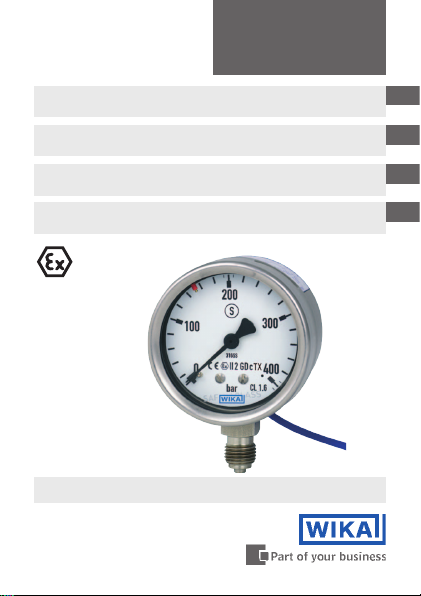
Pressure gauge model 232.3x.063 per directive
94/9/EC (ATEX) with switch contact model 851
Druckmessgerät Typ 232.3x.063 nach Richtlinie
94/9/EG (ATEX) mit Schaltkontakt Typ 851
Manomètre type 232.3x.063 selon directive
94/9/EG (ATEX) avec commutateur type 851
Manómetro modelo 232.3x.063 según directiva
94/9/CE (ATEX) con contacto eléctrico modelo 851
II 2 GD c TX
Model 232.30.63 per ATEX with
switch contact model 851.1
GB
D
F
E
Page 2

Operating instructions model 232.3x.063
GB
per ATEX with model 851
Betriebsanleitung Typ 232.3x.063
D
nach ATEX mit Typ 851
Mode d'emploi type 232.3x.063
F
selon ATEX avec Type 851
de instrucciones modelo 232.3x.063
Manual
E
según ATEX con
© 2009 WIKA Alexander Wiegand SE & Co. KG
All rights reserved. / Alle Rechte vorbehalten.
®
WIKA
is a registered trademark in various countries.
®
WIKA
ist eine geschützte Marke in verschiedenen Ländern.
Prior to starting any work, read the operating instructions!
Keep for later use!
Vor Beginn aller Arbeiten Betriebsanleitung lesen!
Zum späteren Gebrauch aufbewahren!
Lire le mode d‘emploi avant de commencer toute opération !
A conserver pour une utilisation ultérieure !
¡Leer el manual de instrucciones antes de comenzar cualquier trabajo!
¡Guardar el manual para una eventual consulta!
2
modelo
851
WIKA operating instructions model 232.3x.063 with 851 per ATEX
Page 3-15
Seite 17-29
Page 31-42
Página
43-54
11041781.03 03/2011 GB/D/F/E
Page 3

Contents
Contents
Contents
1. General information 4
2. Safety 5
3. Specications 9
4. Design and function 10
5. Transport, packaging and storage 10
6. Commissioning, operation 11
7. Electrical switch contacts 13
8. Maintenance and cleaning 14
9. Dismounting and disposal 14
Appendix 1: Declaration of conformity for model
11041781.03 03/2011 GB/D/F/E
WIKA operating instructions model 232.3x.063 with 851 per ATEX
232.3x.63 with switch contacts model 851
GB
15
3
Page 4

1. General information
1. General information
■
The pressure gauge described in the operating instructions has been
GB
designed and manufactured using state-of-the-art technology.
All components are subject to stringent quality and environmental
criteria during production. Our management systems are certied to
ISO 9001 and ISO 14001.
■
These operating instructions contain important information on handling
the pressure gauge. Working safely requires that all safety instructions
and work instructions are observed.
■
Observe the relevant local accident prevention regulations and general
safety regulations for the pressure gauge's range of use.
■
The operating instructions are part of the product and must be kept in
the immediate vicinity of the pressure gauge and readily accessible to
skilled personnel at any time.
■
Skilled personnel must have carefully read and understood the operating instructions prior to beginning any work.
■
The manufacturer‘s liability is void in the case of any damage caused
by using the product contrary to its intended use, non-compliance with
these operating instructions, assignment of insuciently qualied skilled
personnel or unauthorised modications to the pressure gauge.
■
The general terms and conditions contained in the sales documentation
shall apply.
■
Subject to technical modications.
- Internet address: www.wika.de / www.wika.com
- Relevant data sheet: PM 02.04 and PM 02.11
4
WIKA operating instructions model 232.3x.063 with 851 per ATEX
11041781.03 03/2011 GB/D/F/E
Page 5
1. General information / 2. Safety
Explanation of symbols
WARNING!
... indicates a potentially dangerous situation which can result
in serious injury or death if not avoided.
Information
… points out useful tips, recommendations and information
for ecient and trouble-free operation.
WARNING!
... indicates a potentially dangerous situation in a potentially
explosive atmosphere, resulting in serious injury or death, if
not avoided.
2. Safety
WARNING!
Before installation, commissioning and operation, ensure
that the appropriate pressure gauge has been selected in
terms of measuring range, design and specic measuring
conditions.
Check the compatibility with the medium of the materials
subjected to pressure!
In order to guarantee the measuring accuracy and long-term
stability specied, the corresponding load limits must be
observed.
Non-observance can result in serious injury and/or damage
to the equipment.
Further important safety instructions can be found in the
individual chapters of these operating instructions.
11041781.03 03/2011 GB/D/F/E
WIKA operating instructions model 232.3x.063 with 851 per ATEX
GB
5
Page 6
2. Safety
2.1 Intended use
These pressure gauges are used for measuring pressure and for the switching of switching currents in industrial applications.
GB
The pressure gauge has been designed and built solely for the intended
use described here and may only be used accordingly.
The manufacturer shall not be liable for claims of any type based on operation contrary to the intended use.
2.2 Personnel qualication
WARNING!
Risk of injury if qualication is insucient!
Improper handling can result in considerable injury and
damage to equipment.
The activities described in these operating instructions
may only be carried out by skilled personnel who have the
qualications described below.
Skilled personnel
Skilled personnel are understood to be personnel who, based on their
technical training, knowledge of measurement and control technology and
on their experience and knowledge of country-specic regulations, current
standards and directives, are capable of carrying out the work described
and independently recognising potential hazards.
2.3 Safety instructions for pressure gauges per ATEX
WARNING!
Non-observance of these instructions and their contents may
result in the loss of explosion protection.
WARNING!
It is imperative that the application conditions and safety
requirements of the EC-type examination certicate are
followed.
6
WIKA operating instructions model 232.3x.063 with 851 per ATEX
11041781.03 03/2011 GB/D/F/E
Page 7
2. Safety
■
Pressure gauges must be earthed via the process
connection!
WARNING!
The built-in reed switch does not have its own ignition
source.
It is a 'simple apparatus' in terms of intrinsic safety as dened
in EN 50020.
When powered by a tested and certied intrinsically safe circuit (associated
apparatus), these switches may be used in potentially explosive atmospheres up to category 2 without having to take any further measures.
Operating temperatures
Ambient: -40 ... +60 °C
Medium: The permissible medium temperature does not only depend
For permissible maximum medium temperatures see table 1.
Attention! With gaseous substances, the temperature may increase as
a result of compression warming. In these cases it may be necessary to
throttle the rate of change
of pressure or reduce the permissible medium temperature.
Table 1: Permissible medium temperature
11041781.03 03/2011 GB/D/F/E
WIKA operating instructions model 232.3x.063 with 851 per ATEX
on the instrument design, but also on the ignition temperature
of the surrounding explosive atmosphere. Both aspects have
to be taken into account.
Temperature class of the
ambient explosive atmosphere
(ignition temperature)
T 6 ( > 85 °C) +70 °C
T 5 ( > 100 °C) +85 °C
all other temperature classes +100 °C
Maximum permissible medium
temperature (in the measuring
system)
GB
7
Page 8

2. Safety
2.4 Special hazards
WARNING!
GB
Only work on the gauge with the voltage disconnected.
2.5 Labelling / safety marks
Product label
Observe the information given in the applicable type
examination certicate and the relevant countryspecic regulations for installation and use in potentially
explosive atmospheres (e.g. IEC 60079-14, NEC, CEC).
Non-observance can result in serious injury and/or damage
to the equipment.
For additional important safety instructions see chapter
"2.3 Safety instructions for pressure gauges per ATEX"
WARNING!
When installing, commissioning and operating these
instruments, observe the appropriate national safety
regulations (e.g. VDE 0100).
WARNING!
Residual media in dismounted instruments can result in a
risk to persons, the environment and equipment.
Take sucient precautionary measures.
Date of manufacture
8
WIKA operating instructions model 232.3x.063 with 851 per ATEX
11041781.03 03/2011 GB/D/F/E
Page 9

2. Safety / 3. Specications
Explanation of symbols
Before mounting and commissioning the pressure
gauge, ensure you read the operating instructions!
CE, Communauté Européenne
Instruments bearing this mark comply with the relevant
European directives.
ATEX European Explosion Protection Directive
(Atmosphère = AT, explosible = EX)
Instruments bearing this mark comply with the requirements
of the European Directive 94/9/EC (ATEX) on explosion
protection.
Instruments bearing this mark on the dial are safety pressure
gauges with solid bae wall per EN 837 (S3).
3. Specications
Pressure limitation
Steady: 3/4 x full scale value
Fluctuating: 2/3 x full scale value
Short time: Full scale value
Temperature eect
When the temperature of the measuring system deviates from the reference
temperature (+20 °C):
max. ±0.4 %/10 K of full scale value
IP Ingress protection
Enclosing case IP 54 or IP 65 as special feature (EN 60529 / IEC 529)
11041781.03 03/2011 GB/D/F/E
WIKA operating instructions model 232.3x.063 with 851 per ATEX
GB
9
Page 10

3. Specications ... 5. Transport, packaging and storage
Materials
Wetted parts: Stainless steel
Movement: Stainless steel
GB
Dial and pointer: Aluminium
Case, bayonet ring: Stainless steel (with blow-out back)
Window: Laminated safety glass
For further specications see WIKA data sheet PM 02.04 or PM 02.11 and
the order documentation.
4. Design and function
Description
■
Nominal size 63 mm
■
The instruments measure the pressure by means of resilient bourdon
tube pressure elements
■
The measuring characteristics are in accordance with the EN 837-1
standard
■
In addition, the enclosing and the pressurised components also meet
the requirements of this standard, relating to safety pressure gauges
with a solid bae wall (code S3).
■
When the value exceeds or falls below the set limit, the built-in bistable
reed contact is switched.
Scope of delivery
Cross-check scope of delivery with delivery note.
5. Transport, packaging and storage
5.1 Transport
Check the pressure gauge for any damage that may have been caused by
transport. Obvious damage must be reported immediately.
10
WIKA operating instructions model 232.3x.063 with 851 per ATEX
11041781.03 03/2011 GB/D/F/E
Page 11

5. Transport, packaging ... / 2. 6. Commissioning, operation
5.2 Packaging
Do not remove packaging until just before mounting.
Keep the packaging as it will provide optimum protection during transport
(e.g. change in installation site, sending for repair).
5.3 Storage
Permissible conditions at the place of storage:
Storage temperature: -40 ... +70 °C
6. Commissioning, operation
Mechanical connection
In accordance with the general technical regulations for pressure gauges
(e.g. EN 837-2 "Selection and installation recommendations for pressure
gauges").
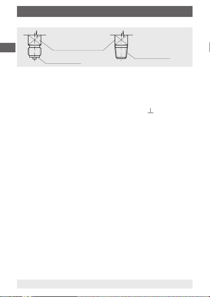
When screwing gauges in, the force required for this must not be applied
through the case or the cable terminal box, but rather through the spanner
ats (using a suitable tool) provided for this purpose on the square shaft of
standard connections.
Installation with
open-ended
spanner
Correct sealing of pressure gauge connections with parallel threads
must be made using suitable sealing rings, sealing washers or WIKA
prole seals. The sealing of tapered threads (e.g. NPT threads) is made
by providing the thread
example, PTFE tape (EN 837-2).
11041781.03 03/2011 GB/D/F/E
WIKA operating instructions model 232.3x.063 with 851 per ATEX
, with additional sealing material such as, for
GB
11
Page 12
6. Commissioning, operation
GB
The torque depends on the seal used. Connecting the gauge using a clamp
socket or a union nut is recommended, so that it is easier to orientate the
gauge correctly. When a blow-out device is tted to a pressure gauge, it
must be protected against being blocked by debris and dirt.
Installation
■
Nominal position per EN 837-1 / 9.6.7, gure 9: 90° ( )
■
Process connection bottom or rear
■
In order to ensure that pressure can be safely and reliably vented
through the case back, a distance of at least 25 mm must be left free
behind the case!
■
In order to avoid any additional heating, the instruments must not be
exposed to direct solar irradiation while in operation!
Permissible vibration load at the installation site
■
The instruments should always be installed in locations free from
vibration
■
If necessary, it is possible to isolate the instrument from the mounting
point by installing a exible connection line between the measuring
point and the pressure gauge and mounting the instrument on a suitable
bracket.
■
If this is not possible, the following limit values must not be exceeded:
Frequency range < 150 Hz
Acceleration < 0.5 g (5 m/s
Commissioning
During the commissioning process pressure surges must be avoided at all
costs. Open the shut-o valves slowly.
12
Spanner ats
Sealing face
2
)
WIKA operating instructions model 232.3x.063 with 851 per ATEX
Sealing in the
thread
11041781.03 03/2011 GB/D/F/E
Page 13
7. Electrical switch contacts
7. Electrical switch contacts
Switching functions
The switching function of the switches is identied by the indices 1 or 2.
851.1 = NO - normally open, contact makes (clockwise pointer motion)
851.2 = NC - normally closed, contact breaks (clockwise pointer motion)
Electrical load
max. switching voltage: AC/DC 24 V
max. contact rating: 10 W
max. current: 0.5 A
Electrical connection
■
The electrical connection must only be made by qualied skilled
personnel.
■
Cable outlet 1 m length, conductor cross section 0.14 mm2, ying leads
■
The terminal assignment is stated on the connection label of the
pressure gauge
WARNING!
■
The instruments do not provide for incorporated
overcurrent protectors.
If overcurrent protectors are requested, these have to be
provided for externally.
■
The instruments must be connected to the equipotential
bonding of the plant.
Switch point adjustment
The set points of the switch points are freely adjustable over the full scale
range.
The switches are set via the mark pointer on the dial's circumference.
The bayonet ring must be removed in order to adjust the switch point.
Electromagnetic compatibility
Reed switches are electrically passive components, which, when used in
accordance with their intended use, do not aect their surroundings.
11041781.03 03/2011 GB/D/F/E
WIKA operating instructions model 232.3x.063 with 851 per ATEX
GB
13
Page 14

8. Maintenance and cleaning / 9. Disposal
8. Maintenance and cleaning
The instruments are maintenance-free.
GB
The indicator and switching function should be checked once or twice every
year. For this the instrument must be disconnected from the process to
check with a pressure testing device.
Repairs must only be carried out by the manufacturer or appropriately
qualied personnel.
Clean the instruments with a moist cloth (soap water).
Prior to cleaning, disconnect the instruments from the mains. Ensure that all
the parts are dry before the power is switched on again.
Residual media in dismounted pressure gauges can result in a risk to
persons, the environment and equipment. Take sucient precautionary
measures.
9. Disposal
Incorrect disposal can put the environment at risk.
Dispose of instrument components and packaging materials in an
environmentally compatible way and in accordance with the country-
specic waste disposal regulations.
14
WIKA operating instructions model 232.3x.063 with 851 per ATEX
11041781.03 03/2011 GB/D/F/E
Page 15

Appendix 1
11041781.03 03/2011 GB/D/F/E
WIKA operating instructions model 232.3x.063 with 851 per ATEX
GB
15
Page 16

GB
11041781.03 03/2011 GB/D/F/E
16
WIKA operating instructions model 232.3x.063 with 851 per ATEX
Page 17

Inhalt
Inhalt
Inhalt
1. Allgemeines 18
2. Sicherheit 19
3. Technische Daten 23
4. Aufbau und Funktion 24
5. Transport, Verpackung und Lagerung 24
6. Inbetriebnahme, Betrieb 25
7. Elektrische Schaltkontakte 27
8. Wartung und Reinigung 28
9. Demontage und Entsorgung 28
Anlage 1:
11041781.03 03/2011 GB/D/F/E
WIKA Betriebsanleitung Typ 232.3x.063 mit 851 nach ATEX
Konformitätserklärung für Typ 232.3x.63 mit
Schaltkontakten Typ 851
D
29
17
Page 18

1. Allgemeines
1. Allgemeines
■
Das in der Betriebsanleitung beschriebene Druckmessgerät wird nach
den neuesten Erkenntnissen konstruiert und gefertigt.
Alle Komponenten unterliegen während der Fertigung strengen Qualitäts- und Umweltkriterien. Unsere Managementsysteme sind nach ISO
D
9001 und ISO 14001 zertiziert.
■
Diese Betriebsanleitung gibt wichtige Hinweise zum Umgang mit dem
Druckmessgerät. Voraussetzung für sicheres Arbeiten ist die Einhaltung
aller angegebenen Sicherheitshinweise und Handlungsanweisungen.
■
Die für den Einsatzbereich des Druckmessgerätes geltenden örtlichen
Unfallverhütungsvorschriften und allgemeinen Sicherheitsbestimmungen einhalten.
■
Die Betriebsanleitung ist Produktbestandteil und muss in unmittelbarer
Nähe des Druckmessgerätes für das Fachpersonal jederzeit zugänglich
aufbewahrt werden.
■
Das Fachpersonal muss die Betriebsanleitung vor Beginn aller Arbeiten
sorgfältig durchgelesen und verstanden haben.
■
Die Haftung des Herstellers erlischt bei Schäden durch bestimmungswidrige Verwendung, Nichtbeachten dieser Betriebsanleitung, Einsatz
ungenügend qualizierten Fachpersonals sowie eigenmächtiger
Veränderung am Druckmessgerät.
■
Es gelten die allgemeinen Geschäftsbedingungen in den Verkaufsunterlagen.
■
Technische Änderungen vorbehalten.
- Internet-Adresse: www.wika.de / www.wika.com
- zugehöriges Datenblatt: PM 02.04 und PM 02.11
18
WIKA Betriebsanleitung Typ 232.3x.063 mit 851 nach ATEX
11041781.03 03/2011 GB/D/F/E
Page 19

1. Allgemeines / 2. Sicherheit
Symbolerklärung
WARNUNG!
… weist auf eine möglicherweise gefährliche Situation hin,
die zum Tod oder zu schweren Verletzungen führen kann,
wenn sie nicht gemieden wird.
Information
… hebt nützliche Tipps und Empfehlungen sowie
Informationen für einen ezienten und störungsfreien Betrieb
hervor.
WARNUNG!
… weist auf eine möglicherweise gefährliche Situation im
explosionsgefährdeten Bereich hin, die zum Tod oder zu
schweren Verletzungen führt, wenn sie nicht gemieden wird.
2. Sicherheit
WARNUNG!
Vor Montage, Inbetriebnahme und Betrieb sicherstellen,
dass das richtige Druckmessgerät hinsichtlich Messbereich,
Ausführung und spezischen Messbedingungen ausgewählt
wurde.
Verträglichkeit der druckbelasteten Werkstoe mit dem
Messsto prüfen!
Die Belastungsgrenzen sind einzuhalten, um die
Messgenauigkeit und die Lebensdauer zu gewährleisten.
Bei Nichtbeachten können schwere Körperverletzungen und/
oder Sachschäden auftreten.
Weitere wichtige Sicherheitshinweise benden sich in den
einzelnen Kapiteln dieser Betriebsanleitung.
11041781.03 03/2011 GB/D/F/E
WIKA Betriebsanleitung Typ 232.3x.063 mit 851 nach ATEX
D
19
Page 20

2. Sicherheit
2.1 Bestimmungsgemäße Verwendung
Diese Druckmessgeräte dienen zum Messen von Druck und Schalten von
Schaltströmen bei industriellen Anwendungen.
Das Druckmessgerät ist ausschließlich für den hier beschriebenen bestimmungsgemäßen Verwendungszweck konzipiert und konstruiert und darf nur
D
dementsprechend verwendet werden.
Ansprüche jeglicher Art aufgrund von nicht bestimmungsgemäßer Ver wendung sind ausgeschlossen.
2.2 Personalqualikation
WARNUNG!
Verletzungsgefahr bei unzureichender Qualikation!
Unsachgemäßer Umgang kann zu erheblichen Personenund Sachschäden führen.
Die in dieser Betriebsanleitung beschriebenen Tätigkeiten
nur durch Fachpersonal nachfolgend beschriebener Qualikation durchführen lassen.
Fachpersonal
Das Fachpersonal ist aufgrund seiner fachlichen Ausbildung, seiner
Kenntnisse der Mess- und Regelungstechnik und seiner Erfahrungen sowie
Kenntnis der landesspezischen Vorschriften, geltenden Normen und Richtlinien in der Lage, die beschriebenen Arbeiten auszuführen und mögliche
Gefahren selbstständig zu erkennen.
2.3 Sicherheitshinweise für Druckmessgeräte nach ATEX
WARNUNG!
Die Nichtbeachtung dieser Inhalte und Anweisungen kann
zum Verlust des Explosionsschutzes führen.
WARNUNG!
Einsatzbedingungen und sicherheitstechnische Daten der
EG Baumusterprüfbescheinigung unbedingt beachten.
20
WIKA Betriebsanleitung Typ 232.3x.063 mit 851 nach ATEX
11041781.03 03/2011 GB/D/F/E
Page 21

2. Sicherheit
■
Druckmessgeräte über den Prozessanschluss erden!
WARNUNG!
Der eingebaute Reedschalter hat keine eigene Zündquelle.
Er ist ein ‚Einfaches Betriebsmittel‘ im Sinne der
Eigensicherheit nach EN 50020.
Bei Versorgung aus einem geprüften und bescheinigten eigensicheren
Stromkreis (zugehöriges Betriebsmittel) dürfen diese Schalter ohne
weitere Maßnahmen in explosionsgefährdeten Bereichen bis Kategorie 2
eingesetzt werden.
Zulässige Temperaturen
Umgebung: -40 ... +60 °C
Messsto: Die zulässige Messstotemperatur hängt außer von
Maximal zulässige Grenzwerte siehe Tabelle 1.
Achtung! Bei gasförmigen Stoen kann sich die Temperatur durch
Kompressionswärme erhöhen. In solchen Fällen muss ggf. die Druckände-
rungsgeschwindigkeit gedrosselt bzw. die zulässige Messstotemperatur
reduziert werden.
Tabelle 1: Zulässige Messstotemperatur
11041781.03 03/2011 GB/D/F/E
der Gerätebauart auch von der Zündtemperatur der
umgebenden explosionsfähigen Atmosphäre ab.
Beide Aspekte sind zu berücksichtigen.
Temperaturklasse der
umgebenden zündfähigen
Atmosphäre (Zündtemperatur)
T 6 ( > 85 °C) +70 °C
T 5 ( > 100 °C) +85 °C
alle anderen Temperaturklassen +100 °C
WIKA Betriebsanleitung Typ 232.3x.063 mit 851 nach ATEX
Zulässige maximale Messsto-
temperatur (im Messsystem)
D
21
Page 22

2. Sicherheit
2.4 Besondere Gefahren
WARNUNG!
Die Angaben der geltenden Baumusterprüfbescheinigung
sowie die jeweiligen landesspezischen Vorschriften zur
D
Alle Arbeiten dürfen nur im spannungslosen Zustand erfolgen.
2.5 Beschilderung / Sicherheitskennzeichnungen
Typenschild
Installation und Einsatz in explosionsgefährdeten Bereichen
(z. B. IEC 60079-14, NEC, CEC) einhalten. Bei Nichtbeachten können schwere Körperverletzungen und/oder
Sachschäden auftreten.
Weitere wichtige Sicherheitshinweise für Geräte mit
ATEX-Zulassung siehe Kapitel "2.3 Sicherheitshinweise für
Druckmessgeräte nach ATEX"
WARNUNG!
Bei Montage, Inbetriebnahme und Betrieb dieser Geräte
unbedingt die entsprechenden nationalen Sicherheitsvor-
schriften (z. B. VDE 0100) beachten.
WARNUNG!
Messstoreste in ausgebauten Geräten können zur
Gefährdung von Personen, Umwelt und Einrichtung führen.
Ausreichende Vorsichtsmaßnahmen ergreifen.
22
WIKA Betriebsanleitung Typ 232.3x.063 mit 851 nach ATEX
Herstellungsdatum
11041781.03 03/2011 GB/D/F/E
Page 23

2. Sicherheit / 3. Technische Daten
Symbolerklärung
Vor Montage und Inbetriebnahme des Druckmessgerätes unbedingt die Betriebsanleitung lesen!
CE, Communauté Européenne
Geräte mit dieser Kennzeichnung stimmen überein mit den
zutreenden europäischen Richtlinien.
ATEX Europäische Explosionsschutz-Richtlinie
(Atmosphère = AT, explosible = EX)
Geräte mit dieser Kennzeichnung stimmen überein mit den
Anforderungen der europäischen Richtlinie 94/9/EG (ATEX)
zum Explosionsschutz.
Geräte mit dieser Kennzeichnung auf dem Zierblatt sind
Sicherheitsdruckmessgeräte mit bruchsicherer Trennwand
nach EN 837 (S3).
3. Technische Daten
Druckbelastbarkeit
Ruhebelastung: 3/4 × Skalenendwert
Wechselbelastung: 2/3 × Skalenendwert
kurzzeitig: Skalenendwert
Temperatureinuss
Bei Abweichung von der Referenztemperatur am Messsystem (+20 °C):
max. ±0,4%/10 K vom jeweiligen Skalenendwert
IP-Schutzart
Umhüllendes Gehäuse IP 54 bzw. IP 65 als Sonderheit (EN 60529/IEC 529)
11041781.03 03/2011 GB/D/F/E
WIKA Betriebsanleitung Typ 232.3x.063 mit 851 nach ATEX
D
23
Page 24

3. Technische Daten ... 5. Transport, Verpackung ...
Werkstoe
Messstoberührte Teile: CrNi-Stahl
Zeigerwerk: CrNi-Stahl
Zierblatt und Zeiger: Aluminium
Gehäuse, Bajonettring: CrNi-Stahl (mit ausblasbarer Rückwand)
Sichtscheibe: Mehrschichten-Sicherheitsglas
D
Weitere technische Daten siehe WIKA Datenblatt PM 02.04 bzw. PM 02.11
und Bestellunterlagen.
4. Aufbau und Funktion
Beschreibung
■
Nenngröße 63 mm
■
Die Geräte erfassen den zu messenden Druck mit elastischen
Rohrfeder-Messgliedern
■
Die messtechnischen Eigenschaften entsprechen der Norm EN 837-1
■
Die umhüllenden und druckbeaufschlagten Bauteile erfüllen außerdem
die Anforderungen dieser Norm an Sicherheitsdruckmessgeräte mit
bruchsicherer Trennwand (Kurzzeichen S3).
■
Beim Über- oder Unterschreiten des eingestellten Grenzwertes wird der
eingebaute bistabile Reedkontakt geschaltet.
Lieferumfang
Lieferumfang mit dem Lieferschein abgleichen.
5. Transport, Verpackung und Lagerung
5.1 Transport
Druckmessgerät auf eventuell vorhandene Transportschäden untersuchen.
Oensichtliche Schäden unverzüglich mitteilen.
24
WIKA Betriebsanleitung Typ 232.3x.063 mit 851 nach ATEX
11041781.03 03/2011 GB/D/F/E
Page 25

5. Transport, Verpackung ... / 6. Inbetriebnahme, Betrieb
5.2 Verpackung
Verpackung erst unmittelbar vor der Montage entfernen.
Die Verpackung aufbewahren, denn diese bietet bei einem Transport einen
optimalen Schutz (z. B. wechselnder Einbauort, Reparatursendung).
5.3 Lagerung
Zulässige Bedingungen am Lagerort
Lagertemperatur: -40 ... +70 °C
6. Inbetriebnahme, Betrieb
Mechanischer Anschluss
Entsprechend den allgemeinen technischen Regeln für Druckmessgeräte
(z. B. EN 837-2 "Auswahl- und Einbauempfehlungen für Druckmessgeräte").
Beim Einschrauben der Geräte darf die zum Abdichten erforderliche Kraft
nicht über das Gehäuse oder die Kabelanschlussdose aufgebracht werden,
sondern mit geeignetem Werkzeug nur über die dafür vorgesehenen
Schlüsselächen am Vierkant des Anschlusszapfens.
Montage mit
Gabelschlüssel
Zur Abdichtung der Druckmessgeräteanschlüsse mit zylindrischen Gewin-
de an der Dichtäche
Proldichtungen einzusetzen. Bei kegeligen Gewinde (z. B. NPT-Gewinde)
erfolgt die Abdichtung im Gewinde
wie z. B. PTFE-Band (EN 837-2).
11041781.03 03/2011 GB/D/F/E
WIKA Betriebsanleitung Typ 232.3x.063 mit 851 nach ATEX
sind Flachdichtungen, Dichtlinsen oder WIKA-
, mit zusätzlichen Dichtwerkstoen,
D
25
Page 26

6. Inbetriebnahme, Betrieb
Schlüsseläche
Dichtäche
D
Das Anzugsmoment ist von der eingesetzten Dichtung abhängig. Um das
Messgerät in die Stellung zu bringen, in der es sich am besten ablesen
lässt, ist ein Anschluss mit Spannmue oder Überwurfmutter zu empfehlen.
Sofern ein Druckmessgerät eine Ausblasvorrichtung besitzt, muss diese vor
Blockierung durch Geräteteile oder Schmutz geschützt sein.
Installation
■
Nennlage nach EN 837-1 / 9.6.7, Bild 9: 90° ( )
■
Prozessanschluss unten bzw. rückseitig
■
Damit im Fehlerfall die sichere Druckentlastung durch die Rückwand
erfolgen kann, müssen hinter dem Gehäuse mindestens 25 mm frei
bleiben!
■
Um zusätzliche Aufheizung zu vermeiden, dürfen die Geräte im Betrieb
keiner direkten Sonneneinstrahlung ausgesetzt werden!
Zulässige Schwingungsbelastung am Einbauort
■
Die Geräte sollten grundsätzlich nur an Stellen ohne Schwingungsbelastung eingebaut werden
■
Gegebenenfalls kann z. B. durch eine exible Verbindungsleitung von
der Messstelle zum Druckmessgerät und die Befestigung über eine
Messgerätehalterung eine Entkopplung vom Einbauort erreicht werden.
■
Falls dies nicht möglich ist, dürfen folgende Grenzwerte nicht überschritten werden:
Frequenzbereich < 150 Hz
Beschleunigung < 0,5 g (5 m/s
Inbetriebnahme
Bei Inbetriebnahme Druckstöße unbedingt vermeiden, Absperrventile
langsam önen.
26
2
)
WIKA Betriebsanleitung Typ 232.3x.063 mit 851 nach ATEX
Abdichtung im
Gewinde
11041781.03 03/2011 GB/D/F/E
Page 27

7. Elektrische Schaltkontakte
7. Elektrische Schaltkontakte
Schaltfunktionen
Die Schaltfunktion der Schalter wird durch die Kennzahlen 1 oder 2
beschrieben.
851.1 = Schließer (bei Zeigerbewegung im Uhrzeigersinn)
851.2 = Öner (bei Zeigerbewegung im Uhrzeigersinn)
Elektrische Belastung
max. Schaltspannung: AC/DC 24 V
max. Schaltleistung: 10 W
max. Stromstärke: 0,5 A
Elektrischer Anschluss
■
Der elektrische Anschluss darf nur durch qualiziertes Personal erfolgen
■
Kabelausgang 1 m Länge, Leitungsquerschnitt 0,14 mm2, freie
Kabelenden
■
Klemmenbelegung auf Anschlussschild am Druckmessgerät
WARNUNG!
■
In den Geräten sind keine Überstromschutzeinrichtungen
eingebaut.
Falls Schutzeinrichtungen gefordert werden, sind
diese extern vorzusehen.
■
Die Geräte sind in den Potenzialausgleich der Anlage mit
einzubeziehen!
Schaltpunkteinstellung
Die Sollwerte der Schaltpunkte sind über den gesamten Skalenbereich frei
einstellbar.
Einstellen der Schalter über den Markenzeiger am Zierblattumfang.
Zum Verstellen des Schaltpunktes ist der Bajonettring abzunehmen.
Elektromagnetische Verträglichkeit
Reedschalter sind elektrisch passive Teile, die bei bestimmungsgemäßem
Betrieb ihre Umgebung nicht beeinussen.
11041781.03 03/2011 GB/D/F/E
WIKA Betriebsanleitung Typ 232.3x.063 mit 851 nach ATEX
D
27
Page 28

8. Wartung und Reinigung / 9. Entsorgung
8. Wartung und Reinigung
Die Geräte sind wartungsfrei.
Eine Überprüfung der Anzeige und der Schaltfunktion sollte etwa 1 bis 2
mal pro Jahr erfolgen. Dazu ist das Gerät vom Prozess zu trennen und mit
einer Druckprüfvorrichtung zu kontrollieren.
D
Reparaturen sind ausschließlich vom Hersteller oder entsprechend
qualiziertem Personal durchzuführen.
Reinigen der Geräte mit einem (in Seifenlauge) angefeuchteten Tuch.
Zur Reinigung sind die Geräte vom Netz zu trennen. Vor Wiedereinschalten
des Stromes ist sicherzustellen, dass alle Teile abgetrocknet sind.
Messstoreste in ausgebauten Druckmessgeräten können zur Gefährdung
von Menschen, Umwelt und Einrichtung führen. Ausreichende Vorsichtsmaßnahmen sind zu ergreifen.
9. Entsorgung
Durch falsche Entsorgung können Gefahren für die Umwelt entstehen.
Gerätekomponenten und Verpackungsmaterialien entsprechend den
landesspezischen Abfallbehandlungs- und Entsorgungsvorschriften
umweltgerecht entsorgen.
28
WIKA Betriebsanleitung Typ 232.3x.063 mit 851 nach ATEX
11041781.03 03/2011 GB/D/F/E
Page 29

Anlage 1
11041781.03 03/2011 GB/D/F/E
WIKA Betriebsanleitung Typ 232.3x.063 mit 851 nach ATEX
D
29
Page 30

D
11041781.03 03/2011 GB/D/F/E
30
WIKA Betriebsanleitung Typ 232.3x.063 mit 851 nach ATEX
Page 31

Sommaire
Sommaire
Sommaire
1. Généralités 32
2. Sécurité 33
3. Particularités 37
4. Conception et fonction 38
5. Transport, emballage et stockage 38
6. Mise en service, exploitation 39
7. Contacts électriques 41
8. Entretien et nettoyage 42
9. Démontage et mise au rebut 42
Appendice 1 :
11041781.03 03/2011 GB/D/F/E
WIKA Mode d'emploi type 232.3x.063 avec 851 selon ATEX
Déclaration de conformité pour le type
232.3X.63 avec contacts électriques type 851
F
29
31
Page 32

1. Généralités
1. Généralités
■
Le manomètre décrit dans le mode d'emploi est conçu et fabriqué selon
les dernières technologies en vigueur. Tous les composants sont soumis
à des critères de qualité et d'environnement stricts durant la fabrication.
Nos systèmes de gestion sont certiés selon ISO 9001 et ISO 14001.
■
Ce mode d'emploi donne des indications importantes concernant
l'utilisation du manomètre. Il est possible de travailler en toute sécurité
F
avec ce produit en respectant toutes les consignes de sécurité et
d'utilisation.
■
Respecter les prescriptions locales de prévention contre les accidents
et les prescriptions générales de sécurité en vigueur pour le domaine
d‘application du manomètre.
■
Le mode d'emploi fait partie de l'appareil et doit être conservé à
proximité immédiate du manomètre et accessible à tout moment pour le
personnel qualié.
■
Le personnel qualié doit, avant de commencer toute opération, avoir lu
soigneusement et compris le mode d'emploi.
■
La responsabilité du fabricant n'est pas engagée en cas de dommages
provoqués par une utilisation non conforme à l'usage prévu, de non
respect de ce mode d'emploi, d'utilisation de personnel peu qualié
de même qu'en cas de modications du transmetteur de pression
eectuées par l'utilisateur.
■
Les conditions générales de vente mentionnées dans les documents de
vente s'appliquent.
■
Sous réserve de modications techniques.
- Consulter notre site internet : www.wika.fr
- Fiche technique correspondante : PM 02.04 et PM 02.11
32
WIKA Mode d'emploi type 232.3x.063 avec 851 selon ATEX
11041781.03 03/2011 GB/D/F/E
Page 33

1. Généralités / 2. Sécurité
Explication des symboles
AVERTISSEMENT !
… indique une situation présentant des risques susceptibles
de provoquer la mort ou des blessures graves si elle n'est
pas évitée.
Information
… met en exergue les conseils et recommandations utiles
de même que les informations permettant d'assurer un
fonctionnement ecace et normal.
AVERTISSEMENT !
… indique une situation en zone explosive présentant des
risques susceptibles de provoquer la mort ou des blessures
graves si elle n'est pas évitée.
2. Sécurité
AVERTISSEMENT !
Avant le montage, la mise en service et le fonctionnement,
s'assurer que l'indicateur de pression portable et le capteur
de pression ont été choisi de façon adéquate, en ce qui
concerne la plage de mesure, la version et les conditions de
mesure spéciques.
Vérier si les matériaux soumis à la pression sont compatibles avec le uide de mesure !
Les limites de surpression admissible sont à respecter an
d'assurer la précision et la durée de vie.
Un non-respect de cette consigne peut entraîner des
blessures corporelles graves et/ou des dégâts matériels.
Vous trouverez d'autres consignes de sécurité dans les
sections individuelles du présent mode d'emploi.
11041781.03 03/2011 GB/D/F/E
WIKA Mode d'emploi type 232.3x.063 avec 851 selon ATEX
F
33
Page 34

2. Sécurité
2.1 Utilisation conforme à l'usage prévu
Ces manomètres sont utilisés pour la mesure de pression et la commutation
de courants de commutation dans les applications industrielles.
Le manomètre est conçu et construit exclusivement pour une utilisation
conforme à l'usage prévu décrit ici et ne doit être utilisé qu'en conséquence.
Aucune réclamation ne peut être recevable en cas d'utilisation non
conforme à l'usage prévu.
F
2.2 Qualication du personnel
AVERTISSEMENT !
Danger de blessure en cas de qualication insusante!
Une utilisation non conforme peut entraîner d'importants
dommages corporels et matériels.
Les opérations décrites dans ce mode d'emploi ne doivent
être eectuées que par un personnel ayant la qualication
décrite ci-après.
Personnel qualié
Le personnel qualié est, en raison de sa formation spécialisée, de ses
connaissances dans le domaine de la technique de mesure et de régulation
et de ses expériences de même que de sa connaissance des prescriptions
nationales des normes et directives en vigueur, en mesure d'eectuer les
travaux décrits et de reconnaître automatiquement les dangers potentiels.
2.3 Instructions de sécurité pour les manomètres selon ATEX
AVERTISSEMENT !
Le non respect de ces instructions et de leurs contenus peut
entraîner une perte de la protection contre les explosions.
AVERTISSEMENT !
Les consignes de sécurité de l'attestation d'examen de type
et les conditions d'application doivent impérativement être
respectées.
34
WIKA Mode d'emploi type 232.3x.063 avec 851 selon ATEX
11041781.03 03/2011 GB/D/F/E
Page 35

2. Sécurité
■
Les manomètres doivent être mis à la terre à l'aide du
branchement de process !
AVERTISSEMENT !
Le contact reed intégré ne possède pas de source
d'allumage propre.
C'est un "simple appareil" en termes de sécurité intrinsèque
comme dénie dans la norme EN 50020.
Lorsqu'ils sont alimentés par un circuit testé et certié intrinsèquement
sûrs (appareil associé), ces commutateurs peuvent être utilisés dans des
atmosphères potentiellement explosives allant jusqu'à la catégorie 2 sans
avoir à prendre d'autres mesures.
Température d'exploitation
Ambiante: -40 ... +60 °C
Fluide: La température admissible du uide ne dépend pas seulement de
la fabrication de l'instrument, mais également de la température
d'allumage entourant l'atmosphère explosive. Ces deux aspects
doivent être pris en compte.
Pour ce qui concerne les températures maximales admissibles
du uide, voir tableau 1.
Attention ! Avec les substances gazeuses, la température pourrait
augmenter à la suite d'un réchauement de compression. Dans ces cas-là,
il peut s'avérer nécessaire d'accélérer le taux de changement de pression
ou de réduire la température du uide admissible.
Tableau 1 : température du uide admissible
Classe de température de
l'atmosphère explosive ambiante
(température d'allumage)
T 6 ( > 85 °C) +70 °C
T 5 ( > 100 °C) +85 °C
toutes les autres classes de température +100 °C
11041781.03 03/2011 GB/D/F/E
WIKA Mode d'emploi type 232.3x.063 avec 851 selon ATEX
Température du uide
admissible maximale
(dans le système de mesure)
F
35
Page 36

2. Sécurité
2.4 Dangers particuliers
AVERTISSEMENT !
Respecter les indications de l'attestation d'examen de
type valable de même que les prescriptions nationales
respectives concernant l'installation et l'utilisation en zone
explosive (par exemple CEI 60079-14, NEC, CEC). Un
non-respect de cette consigne peut entraîner des blessures
F
Toutes les interventions doivent être eectuées hors tension.
2.5 Etiquetage / Marquages de sécurité
Plaque signalétique
corporelles graves et/ou des dégâts matériels.
Pour des instructions de sécurité supplémentaires impor-
tantes, voir le Chapitre "2.3 Instructions de sécurité pour
manomètres selon ATEX"
AVERTISSEMENT !
Lors du montage, de la mise en service et du fonctionnement
de ces instruments, respectez impérativement les consignes
de sécurité nationales pertinentes (p. ex. VDE 0100).
AVERTISSEMENT !
Les restes de uides se trouvant dans les indicateurs de
pression portables ou le capteur de pression démonté
peuvent mettre en danger les personnes, l'environnement
ainsi que l'installation.
Prendre des mesures de sécurité susantes.
Date de fabrication
36
WIKA Mode d'emploi type 232.3x.063 avec 851 selon ATEX
11041781.03 03/2011 GB/D/F/E
Page 37

2. Sécurité / 3. Spécications
Explication des symboles
Lire impérativement le mode d'emploi avant le
montage et la mise en service de l'indicateur de
pression portable !
CE, Communauté Européenne
Les appareils avec ce marquage sont conformes aux
directives européennes pertinentes.
ATEX Directive européenne sur les appareils destinés
à être utilisés en atmosphère explosible
(Atmosphère = AT, explosible = EX)
Les appareils avec ce marquage sont conformes aux
exigences de la directive européenne 94/9/CE (ATEX) sur
la protection contre les explosions.
Les appareils avec ce marquage sur le cadran sont des
manomètres de sécurité dotés d‘une cloison de sécurité
incassable selon EN 837 (S3).
3. Spécications
Plages d' utilisation
Statique : 3/4 x valeur pleine échelle
Fluctuation : 2/3 x valeur pleine échelle
Momentané : valeur pleine échelle
Eet de la température
Au cas où la température du système de mesure dévie de la température de
référence (+20 °C) : max. ±0,4 %/10 K de la valeur pleine échelle
IP Indice de protection
Caisse de protection IP 54 ou IP 65 comme caractéristique spéciale
(EN 60529 / IEC 529)
11041781.03 03/2011 GB/D/F/E
WIKA Mode d'emploi type 232.3x.063 avec 851 selon ATEX
F
37
Page 38

3. Spécications ... 5. Transport, emballage et stockage
Matériaux
Pièces en contact avec le uide : Acier inox
Mouvement: Acier inox
Cadran et aiguille: aluminium
Boîtier, lunette: acier inox (avec paroi arrière éjectable)
Voyant: verre de sécurité feuilleté
Pour de plus amples spécications, voir la che technique WIKA PM 02.04
ou PM 02.11 et la documentation de commande.
F
4. Conception et fonction
Description
■
Diamètre : 63 mm
■
Les appareils mesurent la pression par le biais d’un tube manométrique
à déformation élastique
■
Les caractéristiques techniques de mesure correspondent aux normes
EN 837-1
■
En outre, les composants scellés et pressurisés respectent aussi les
exigences de ce standard, en ce qui concerne les manomètres de
sécurité dotés d‘une cloison de sécurité incassable (code S3).
■
Si le seuil réglé est dépassé, le contact reed monté est commuté
Détail de la livraison
Comparer le détail de la livraison avec le bordereau de livraison.
5. Transport, emballage et stockage
5.1 Transport
Vérier s'il existe des dégâts sur le manomètre liés au transport. Communiquer immédiatement les dégâts constatés.
38
WIKA Mode d'emploi type 232.3x.063 avec 851 selon ATEX
11041781.03 03/2011 GB/D/F/E
Page 39

5. Transport, emballage ... / 6. Mise en service, exploitation
5.2 Emballage
N'enlever l'emballage qu'avant le montage.
Conserver l'emballage, celui-ci ore, lors d'un transport, une protection
optimale (par ex. changement de lieu d'utilisation, renvoi pour réparation).
5.3 Stockage
Conditions admissibles sur le lieu de stockage :
Température de stockage : -40 ... +70 °C
6. Mise en service, exploitation
Raccordement mécanique
Conformément aux règles techniques générales pour les manomètres
(par ex. EN 837-2 "Recommandations sur le choix et l'installation des
manomètres").
Lors du vissage des appareils, la force nécessaire ne doit pas être appliquée sur le boîtier ou sur le boîtier de raccordement mais seulement sur les
surfaces prévues par un outil approprié sur le carré du raccord.
Montage avec
clé à fourche
Pour assurer l'étanchéité du raccord avec letage cylindrique du manomètre
sur la surface d'étanchéité
lentille ou les joints à écrasement WIKA. Pour les letages coniques (par
exemple letage NPT) l'étanchéité sur le letage
plus un matériau d'étanchéité comme par exemple la bande PTFE (selon
EN 837-2).
11041781.03 03/2011 GB/D/F/E
WIKA Mode d'emploi type 232.3x.063 avec 851 selon ATEX
il faut utiliser des joints plats, des joints forme
se fait en utilisant en
F
39
Page 40

6. Mise en service, exploitation
Clef plate
Surface d'étanchéité
Le couple de serrage dépend du joint utilisé. An de positionner l'appareil
de mesure de façon à ce qu'il soit facilement lisible, il est recommandé
d'utiliser un manchon de serrage ou un écrou-chapeau. Au cas où un
F
manomètre est équipé d'une paroi arrière éjectable, celle-ci doit être
protégée contre un blocage par des pièces d'appareil et contre la crasse.
Installation
■
Position de base selon EN 837-1 / 9.6.7. image 9: 90° ( )
■
Raccord pression vertical ou arrière
■
Pour qu'une surpression puisse s'évacuer en toute sécurité par l'arrière
du boîtier en cas d'incident sur un manomètre, une distance minimum
de 25 mm doit rester libre à l'arrière du boîtier de l'appareil!
■
An d'éviter tout échauement supplémentaire, les instruments ne
doivent pas être exposés directement aux rayons du soleil pendant le
fonctionnement !
Contrainte de vibration admissible sur le point de montage
■
L'instrument ne doit être installé que dans des endroits exempts de
vibrations.
■
Le cas échéant, il est possible d'isoler l'appareil du lieu d'installation en
utilisant par exemple une liaison exible entre le point de mesure et le
manomètre et en xant ce dernier à l'aide d'un support d'appareil mural.
■
Lorsque cela n'est pas possible, veiller à ce que les valeurs limites
suivantes ne soient pas dépassées :
Plage de fréquence < 150 Hz
Accélération < 0.5 g (5 m/s
Mise en service
Lors de la mise en service il faut absolument éviter les coups de bélier.
Ouvrir lentement les robinets d'isolement.
40
WIKA Mode d'emploi type 232.3x.063 avec 851 selon ATEX
2
)
Etanchéité sur
letage
11041781.03 03/2011 GB/D/F/E
Page 41

7. Commutateurs électriques
7. Commutateurs électriques
Fonctions de commutation
La fonction de commutation de l'interrupteur est décrite par les chires
d'identication 1 ou 2.
851.1 = contact à fermeture, normalement ouvert (NO) (si l'aiguille se
déplace dans le sens des aiguilles d'une montre).
851.2 = à ouverture, normalement fermé (NF) (si l'aiguille se déplace dans
le sens des aiguilles d'une montre)
Charge électrique
Tension de commutation max.: 24 VAC/VDC
Puissance de rupture max.: 10 W
Courant maxi.: 0,5 A
Raccordement électrique
■
Les travaux de raccordement électrique ne doivent être eectués que
par des personnels qualiés.
■
Sortie de câble 1 m de longueur, section de conducteurs 0,14 mm2,
extrémités de câble libres
■
L'aectation de borne est indiquée sur l'étiquette de connexion du
manomètre
AVERTISSEMENT !
■
Aucun dispositif de protection de surtension n‘est installé
dans les instruments.
Au cas où des dispositifs de protection sont exigés,
ceux-ci sont à prévoir à l'extérieur.
■
Les appareils sont à inclure dans la compensation de
Réglage du point de commutation
Les points de commutation des contacts sont librement réglable sur toute
l'échelle de mesure.
Les commutateurs sont réglés par le pointeur sur la circonférence du cadran.
La lunette baïonnette doit être enlevé an de régler le point de commutation.
Compatibilité électromagnétique
Les contacts reed sont des composants électriquement passifs, qui,
s'ils sont utilisés conformément à leur usage prévu, n'aectent pas leur
environnement.
11041781.03 03/2011 GB/D/F/E
WIKA Mode d'emploi type 232.3x.063 avec 851 selon ATEX
potentiel de l'installation.
F
41
Page 42

8. Entretien et nettoyage / 9. Mise au rebut
8. Entretien et nettoyage
Les instruments ne requièrent aucun entretien.
Un contrôle de l’achage et de la fonction de commutation est recommandé 1 à 2 fois/an. Pour contrôler l'achage et la fonction de commuta-
tion, l'appareil doit être isolé du processus de mesure et contrôlé à l'aide
d'un dispositif de contrôle de la pression.
Les réparations doivent être eectuées exclusivement par le fabricant ou
F
par un personnel qualié.
Nettoyez les instruments avec un chion humide (eau savonneuse).
Avant le nettoyage, débrancher les instruments du secteur. Assurez-vous
que toutes les pièces sont bien sèches avant de remettre le courant.
Les restes de uides se trouvant dans les indicateurs de pression portables
ou le capteur de pression démonté peuvent mettre en danger les personnes, l'environnement ainsi que l'installation. Prendre des mesures de
sécurité susantes.
9. Mise au rebut
Une mise au rebut inadéquate peut entraîner des dangers pour
l'environnement.
Eliminer les composants des appareils et les matériaux d'emballage
conformément aux prescriptions nationales pour le traitement et
l'élimination des déchets et aux lois de protection de l'environnement en
vigueur.
42
WIKA Mode d'emploi type 232.3x.063 avec 851 selon ATEX
11041781.03 03/2011 GB/D/F/E
Page 43

Contenido
Contenido
Contenido
1. Información general 44
2. Seguridad 45
3. Datos técnicos 49
4. Diseño y función 50
5. Transporte, embalaje y almacenamiento 50
6. Puesta en servicio, funcionamiento 51
7. Contactos de conmutación eléctricos 53
8. Mantenimiento y limpieza 54
9. Desmontaje y eliminación 54
Anexo 1:
11041781.03 03/2011 GB/D/F/E
WIKA manual de instrucciones modelo 232.3x.063 con 851 según ATEX
Declaración de conformidad para los modelo
232.3x.63 con contactos eléctricos modelo 851
E
29
43
Page 44

6. Inbet
1. Información general
■
El manómetro descrito en el manual de instrucciones está construido
y fabricado según los conocimientos actuales. Todos los componentes
están sujetos a criterios rígidos de calidad y medio ambiente durante la
producción. Nuestros sistemas de gestión están certicados según ISO
9001 e ISO 14001.
■
Este manual de instrucciones proporciona indicaciones importantes
acerca del manejo del manómetro. Para un trabajo seguro, es imprescindible cumplir con todas las instrucciones de seguridad y manejo
indicadas.
E
■
Cumplir siempre las normativas sobre la prevención de accidentes y las
normas de seguridad en vigor en el lugar de utilización del manómetro.
■
El manual de instrucciones es una parte integrante del manómetro
y debe guardarse en la proximidad del mismo para que el personal
especializado pueda consultarlo en cualquier momento.
■
El personal especializado debe haber leído y entendido el manual de
instrucciones antes de comenzar cualquier trabajo.
■
El fabricante queda exento de cualquier responsabilidad en caso de
daños causados por un uso no conforme a la nalidad prevista, la
inobservancia del presente manual de instrucciones, un manejo por
personal insucientemente cualicado así como una modicación no
autorizada del manómetro.
■
Se aplican las condiciones generales de venta incluidas en la documentación de venta.
■
Modicaciones técnicas reservadas.
- Página web: www.wika.es
- Hoja técnica correspondiente: PM 02.04 y PM 02.11
WIKA manual de instrucciones modelo 232.3x.063 con 851 según ATEX
44
11041781.03 03/2011 GB/D/F/E
Page 45

2. Seguridad
Explicación de símbolos
¡ADVERTENCIA!
… indica una situación probablemente peligrosa que pueda
causar la muerte o lesiones graves si no se evita.
Información
... marca consejos y recomendaciones útiles así como
informaciones para una utilización ecaz y libre de fallos.
¡ADVERTENCIA!
… indica una situación probablemente peligrosa en una
atmósfera potencialmente explosiva que causa la muerte o
lesiones graves si no se evita.
2. Seguridad
¡ADVERTENCIA!
Antes del montaje, la puesta en servicio y el funcionamiento
asegurarse de que se haya seleccionado el manómetro
adecuado con respecto a rango de medida, versión y condi-
ciones de medición especícas.
¡Asegúrese de que los productos bajo presión sean aptos
para el material de medición!
Para garantizar la precisión de medición y la durabilidad del
instrumento, se deberán respetar los límites de carga.
El no respetar las instrucciones puede generar lesiones
graves y/o daños materiales.
Los distintos capítulos de este manual de instrucciones
contienen otras importantes indicaciones de seguridad.
11041781.03 03/2011 GB/D/F/E
WIKA manual de instrucciones modelo 232.3x.063 con 851 según ATEX
E
45
Page 46

2. Seguridad
2.1 Uso conforme a lo previsto
Estos manómetros se utilizan para medir presiones y realizar conmutaciones de corrientes eléctricas en aplicaciones industriales.
El manómetro ha sido diseñado y construido únicamente para la nalidad
aquí descrita y debe utilizarse en conformidad a la misma.
No se admite ninguna reclamación debido a un manejo no adecuado.
2.2 Cualicación del personal
¡ADVERTENCIA!
E
Personal especializado
Debido a su formación profesional, a sus conocimientos de la técnica de
regulación y medición así como a su experiencia y su conocimiento de las
normativas, normas y directivas vigentes en el país de utilización el personal especializado es capaz de ejecutar los trabajos descritos y reconocer
posibles peligros por sí solo.
2.3 Instrucciones de seguridad para manómetros según ATEX
46
¡Riesgo de lesiones debido a una insuciente cualicación!
Un manejo no adecuado puede causar considerables daños
personales y materiales.
Las actividades descritas en este manual de instrucciones
deben realizarse únicamente por personal especializado con
la consiguiente cualicación.
¡ADVERTENCIA!
La inobservancia del contenido y de las instrucciones puede
originar la pérdida de la protección contra explosiones.
¡ADVERTENCIA!
Es imprescindible observar las condiciones de uso y los
datos de seguridad del certicado CE de tipo.
WIKA manual de instrucciones modelo 232.3x.063 con 851 según ATEX
11041781.03 03/2011 GB/D/F/E
Page 47

2. Seguridad
■
¡Poner a tierra los manómetros a través de la conexión
al proceso!
¡ADVERTENCIA!
El contacto Reed incorporado no tiene ninguna fuente de
ignición propia.
Es un equipo sencillo en el sentido de la seguridad intrínseca
según EN 50020.
Si la alimentación se realiza mediante un circuito de seguridad intrínseca
comprobado y certicado (equipo correspondiente), estos contactos
pueden utilizarse sin medidas añadidas en las atmósferas potencialmente
explosivas hasta la categoría 2.
Temperaturas admisibles
Ambiente -40 ... +60 °C
Medio: La temperatura del medio admisible depende del tipo de
construcción del instrumento y de la temperatura de inamación
de la atmósfera potencialmente explosiva en el ambiente.
Es preciso considerar los dos valores.
Para los valores límite máx. admisibles, véase la tabla 1.
¡Atención! La temperatura puede aumentar con medios gaseosos a causa
del calor de compresión. En estos casos, hay que disminuir la velocidad
de cambio de presión o reducir la temperatura admisible del medio si fuera
necesario.
Tabla 1: Temperatura admisible del medio
Clase de temperatura de la
atmósfera ambiente inamable
(temperatura de inamación)
T 6 ( > 85 °C) +70 °C
T 5 ( > 100 °C) +85 °C
Todas las otras clases de temperatura +100 °C
11041781.03 03/2011 GB/D/F/E
WIKA manual de instrucciones modelo 232.3x.063 con 851 según ATEX
Temperatura máx. admisible
del medio (en el sistema de
medición)
E
47
Page 48

2. Seguridad
2.4 Riesgos especícos
¡ADVERTENCIA!
Cumplir las indicaciones del certicado de tipo así como las
normativas vigentes en el país de utilización acerca de la
instalación y el uso en atmósferas potencialmente explosivas
(p. ej. IEC 60079-14, NEC, CEC). Riesgo de lesiones graves
y/o daños materiales en caso de inobservancia.
Consultar el capítulo "2.3 Instrucciones de seguridad para
instrumentos con certicación ATEX" para más instrucciones
E
Todos los trabajos que se ejecuten en los instrumentos han de hacerse sin
someter el instrumento a presión.
2.5 Rótulos / Marcajes de seguridad
Placa indicadora de modelo
de seguridad importantes
¡ADVERTENCIA!
Es imprescindible observar las prescripciones nacionales de
seguridad (p. ej. VDE 0100). durante el montaje, la puesta en
servicio y la operación de estos aparatos.
¡ADVERTENCIA!
Restos de medios en instrumentos desmontados pueden
causar riesgos para personas, medio ambiente e instalación.
Tomar adecuadas medidas de precaución.
WIKA manual de instrucciones modelo 232.3x.063 con 851 según ATEX
48
Fecha de fabricación
11041781.03 03/2011 GB/D/F/E
Page 49

2. Seguridad / 3. Datos técnicos
Explicación de símbolos
¡Es absolutamente necesario leer el manual de
instrucciones antes del montaje y la puesta en
servicio del manómetro!
CE, Communauté Européenne
Los instrumentos con este marcaje cumplen las
directivas europeas aplicables.
ATEX Directiva europea para garantizar la seguridad
frente a las explosiones
(Atmosphère = AT, explosible = EX)
Los instrumentos con este marcado están conformes a las
exigencias de la directiva europea 94/9/CE (ATEX) relativa a
la prevención de explosiones.
Los instrumentos con este marcaje en la esfera son
manómetros de seguridad con una pared divisora resistente
a la fractura conforme a EN 837 (S3).
3. Datos técnicos
Presión admisible
Presión estática: 3/4 x valor nal de escala
Presión dinámica: 2/3 x valor nal de escala
Presión puntual: Valor nal de escala
Inuencia de temperatura
En caso de desviación de la temperatura de referencia en el sistema de
medición (+20 °C): max. ± 0,4 %/10 K de la gama de indicación
Tipo de protección IP
Caja envolvente IP 54 o IP 65 como unidad especial (EN 60529/IEC 529)
11041781.03 03/2011 GB/D/F/E
WIKA manual de instrucciones modelo 232.3x.063 con 851 según ATEX
E
49
Page 50

3. Datos técnicos ... 5. Transporte, embalaje ...
Materiales
P
iezas en contacto con el medio
Mecanismo indicador: Acero CrNi
Esfera e indicador: Aluminio
Caja, aro bayoneta: Acero inoxidable (con disco de seguridad)
Mirilla: Cristal laminado de seguridad
Para más datos técnicos véase la hoja técnica de WIKA PM 02.04 o
PM 02.11 y la documentación de pedido.
4. Diseño y función
E
Descripción
■
Diámetro nominal 63 mm
■
Los instrumentos registran la presión a medir con muelles tubulares
exibles
■
Las características técnicas de medición corresponden a la norma
EN 837-1
■
Los componentes envolventes y sometidos a presión cumplen además
los requisitos de la normativa en referencia a manómetros de seguridad
con solidfront (abreviación S3).
■
El contacto Reed biestable se conecta cuando se excede o queda
debajo del valor límite ajustado.
: Acero CrNi
Volumen de suministro
Comparar mediante el albarán si se han entregado todas las piezas.
5. Transporte, embalaje y almacenamiento
5.1 Transporte
Comprobar si el manómetro presenta eventuales daños causados en el
transporte. Noticar daños obvios de forma inmediata.
WIKA manual de instrucciones modelo 232.3x.063 con 851 según ATEX
50
11041781.03 03/2011 GB/D/F/E
Page 51

5. Transporte ... / 6. Puesta en servicio, funcionamiento
5.2 Embalaje
No quitar el embalaje hasta justo antes del montaje.
Guardar el embalaje ya que es la protección ideal para el transporte (por
ejemplo un cambio del lugar de instalación o un envío del instrumento para
posibles reparaciones).
5.3 Almacenamiento
Condiciones admisibles en el lugar de almacenamiento
Temperatura de almacenamiento: -40 ... +70 °C
6. Puesta en servicio, funcionamiento
La conexión mecánica
Conforme a las reglas técnicas generales para manómetros (por ejemplo
EN 837-2 Recomendaciones relativas a la selección y montaje de
manómetros).
Para atornillar el instrumento, se debe utilizar la fuerza mediante el uso de
herramientas adecuadas sobre las supercies planas de ajuste -previstas y
no sobre la caja o la caja de conexiones.
Montaje mediante
llave de boca
Para el cierre de las conexiones de los manómetros con roscas cilíndricas
en la supercie de cierre
juntas perladas WIKA. Para roscas cónicas (por ejemplo, roscas NPT) se
realiza el cierre en la rosca
por ejemplo, cinta PTFE (EN 837-2).
11041781.03 03/2011 GB/D/F/E
WIKA manual de instrucciones modelo 232.3x.063 con 851 según ATEX
se debe instalar juntas planas, arandelas o
con material de cierre complementario, como
E
51
Page 52

6. Puesta en servicio, funcionamiento
Supercie plana
de ajuste
Supercie de cierre
El momento de arranque depende del tipo de cierre utilizado. Para poner el
manómetro en la posición que proporcionará la mejor lectura, se recomienda una conexión con un manguito tensor o tuerca tapón. Si un manómetro
está dotado de un dispositivo de ventilación es necesario protegerlo contra
blocaje por piezas de aparatos o suciedad.
E
Instalación
■
Posiciòn nominal segun EN 837-1 / 9.6.7, ilustr 9: 90° ( )
■
Conexión radial o en el lado posterior
■
¡Asegúrese de que haya un espacio de mín. 25 mm detrás de la caja
para garantizar el alivio seguro de presión a través de la pared trasera
en caso de fallo!
■
¡No exponer los instrumentos a la radiación solar directa durante el
funcionamiento para evitar un calentamiento adicional!
Oscilación admisible en el lugar de instalación
■
Instalar los instrumentos sólo en lugares sin oscilaciones.
■
Si es necesario, el desacoplamiento del lugar de instalación puede
conseguirse por ejemplo mediante una línea de conexión exible del
punto de medición al manómetro
y mediante jación por medio de un soporte para el manómetro.
■
Si esto no es posible, no se debe sobrepasar en ningun caso los
siguientes valores límites:
Rango de frecuencias < 150 Hz
Aceleración < 0,5 g (5 m/s
Puesta en servicio
Evitar golpes de ariete en todo caso durante la puesta en servicio, abrir las
válvulas de cierre despacio.
WIKA manual de instrucciones modelo 232.3x.063 con 851 según ATEX
52
2
)
Junta en
la rosca
11041781.03 03/2011 GB/D/F/E
Page 53

7. Contactos eléctricos
7. Contactos eléctricos
Funciones de conmutación
La función de conmutación de los contactos está indicada por el número
1 ó 2.
851.1 = Cierre de circuito (con movimiento de aguja en sentido del reloj)
851.2 = Apertura de circuito (con movimiento de aguja en sentido de las
agujas del reloj)
Carga eléctrica
Tensión de conmutación máx.: AC/DC 24 V
Potencia de ruptura máx.: 10 W
Corriente máx.: 0,5 A
Conexión eléctrica
■
La conexión eléctrica sólo la puede realizar personal cualicado
■
Salida de cable: longitud de 1 m, sección de cable: 0,14 mm2,
terminales libres
■
Ocupación de bornes según placa de conexión en el manómetro
¡ADVERTENCIA!
■
En los instrumentos no están integrados dispositivos de
seguridad contra sobrecorriente.
Si se necesitan dispositivos de seguridad hay que utilizar
dispositivos exteriores.
■
Integrar los instrumentos en la conexión equipotencial
de la instalación!
Ajuste del punto de interrupción
Los valores nominales de los puntos de interrupción pueden ajustarse
libremente en toda la escala.
El contacto se ajusta mediante la aguja de marcaje en la esfera.
Quitar el aro bayoneta para ajustar el punto de interrupción.
Compatibilidad electromagnética
Los contactos Reed son piezas eléctricamente pasivas que afectan al
ambiente si están utilizados según el uso previsto.
11041781.03 03/2011 GB/D/F/E
WIKA manual de instrucciones modelo 232.3x.063 con 851 según ATEX
E
53
Page 54

8. Mantenimiento y limpieza / 9. Eliminación de residuos
8. Mantenimiento y limpieza
Los instrumentos no requieren mantenimiento.
Controlar el instrumento y la función de conmutación una o dos veces al
año. Para eso, separar el instrumento del proceso y controlarlo con un
dispositivo de control de presión.
Todas las reparaciones debe efectuarlas únicamente el fabricante o
personal idóneo.
Limpiar los instrumentos con un trapo húmedo (mojado en lejía de jabón).
Antes de limpiar desconectar el instrumento de la red. Asegúrese de que
E
todas las partes estén secas antes de reconectar la corriente.
Restos de medios en manómetros desmontados pueden crear riesgos
para personas, medio ambiente e instalación. Tomar adecuadas medidas
de precaución.
9. Eliminación de residuos
Una eliminación incorrecta puede provocar peligros para el medio
ambiente.
Eliminar los componentes de los instrumentos y los materiales de
embalaje conforme a los reglamentos relativos al tratamiento de residuos y
eliminación vigentes en el país de utilización.
WIKA manual de instrucciones modelo 232.3x.063 con 851 según ATEX
54
11041781.03 03/2011 GB/D/F/E
Page 55

WIKA global
Europe
Austria
WIKA Messgerätevertrieb
Ursula Wiegand GmbH & Co. KG
1230 Vienna
Tel. (+43) 1 86916-31
Fax: (+43) 1 86916-34
E-Mail: info@wika.at
www.wika.at
Benelux
WIKA Benelux
6101 WX Echt
Tel. (+31) 475 535-500
Fax: (+31) 475 535-446
E-Mail: info@wika.nl
www.wika.nl
Bulgaria
WIKA Bulgaria EOOD
Bul. „Al. Stamboliiski“ 205
1309 Soa
Tel. (+359) 2 82138-10
Fax: (+359) 2 82138-13
E-Mail: t.antonov@wika.bg
Croatia
WIKA Croatia d.o.o.
Hrastovicka 19
10250 Zagreb-Lucko
Tel. (+385) 1 6531034
Fax: (+385) 1 6531357
E-Mail: info@wika.hr
www.wika.hr
11041781.03 03/2011 GB/D/F/E
WIKA Betriebsanleitung Typ 232.3x.063 mit 851 nach ATEX
Finland
WIKA Finland Oy
00210 Helsinki
Tel. (+358) 9-682 49 20
Fax: (+358) 9-682 49 270
E-Mail: info@wika.
www.wika.
France
WIKA Instruments s.a.r.l.
95610 Eragny-sur-Oise
Tel. (+33) 1 343084-84
Fax: (+33) 1 343084-94
E-Mail: info@wika.fr
www.wika.fr
Germany
WIKA Alexander Wiegand
SE & Co. KG
63911 Klingenberg
Tel. (+49) 9372 132-0
Fax: (+49) 9372 132-406
E-Mail: info@wika.de
www.wika.de
Italy
WIKA Italia Srl & C. sas
20020 Arese (Milano)
Tel. (+39) 02 9386-11
Fax: (+39) 02 9386-174
E-Mail: info@wika.it
www.wika.it
55
Page 56

WIKA global
Poland
WIKA Polska S.A.
87-800 Wloclawek
Tel. (+48) 542 3011-00
Fax: (+48) 542 3011-01
E-Mail: info@wikapolska.pl
www.wikapolska.pl
Russia
ZAO WIKA MERA
127015 Moscow
Tel. (+7) 495-648 01 80
Fax: (+7) 495-648 01 81
E-Mail: info@wika.ru
www.wika.ru
Weitere WIKA Niederlassungen weltweit nden Sie online unter www.wika.de.
Further WIKA subsidiaries worldwide can be found online at www.wika.de.
La liste des autres liales WIKA dans le monde se trouve sur www.wika.de
Otras sucursales WIKA en todo el mundo puede encontrar en www.wika.de.
56
Serbia
WIKA Merna Tehnika d.o.o.
Sime Solaje 15, 11060 Belgrade
Tel. (+381) 11 2763722
Fax: (+381) 11 753674
E-Mail: info@wika.co.yu
www.wika.co.yu
Spain
Instrumentos WIKA, S.A.
C/Josep Carner, 11-17
08205 Sabadell (Barcelona)
Tel. (+34) 902 902577
Fax: (+34) 933 938666
E-Mail: info@wika.es
www.wika.es
WIKA Alexander Wiegand SE & Co. KG
Alexander-Wiegand-Straße 30
63911 Klingenberg • Germany
Tel. (+49) 9372/132-0
Fax (+49) 9372/132-406
E-Mail info@wika.de
www.wika.de
11041781.03 03/2011 GB/D/F/E
 Loading...