

Page 1

Operating instructions
Betriebsanleitung
Mode d‘emploi
Manual de instrucciones
Pressure gauges with switch contacts
Models PGS10, PGS11 and PGS21
Druckmessgeräte mit Schaltkontakten
Typen PGS10, PGS11 und PGS21
Manomètres à contacts électriques
Types PGS10, PGS11 et PGS21
Manómetros con contactos eléctricos
Modelos PGS10, PGS11 y PGS21
Model PGS10 Model PGS11 Model PGS21
GB
D
F
E
Page 2

Operating instructions
GB
Models PGS10, PGS11 and PGS21
Betriebsanleitung
D
Typen PGS10, PGS11 und PGS21
Mode d’emploi
F
Types PGS10, PGS11 et PGS21
Manual de instrucciones
E
Modelos PGS10, PGS11 y PGS21
© 2010 WIKA Alexander Wiegand SE & Co. KG
All rights reserved. / Alle Rechte vorbehalten.
WIKA® is a registered trademark in various countries.
WIKA® ist eine geschützte Marke in verschiedenen Ländern.
Prior to starting any work, read the operating instructions!
Keep for later use!
Vor Beginn aller Arbeiten Betriebsanleitung lesen!
Zum späteren Gebrauch aufbewahren!
Lire le mode d‘emploi avant de commencer toute opération !
A conserver pour une utilisation ultérieure !
¡Leer el manual de instrucciones antes de comenzar cualquier trabajo!
¡Guardar el manual para una eventual consulta!
2
WIKA operating instructions models PGS10, PGS11 and PGS21
Page 3-18
Seite 19-34
Page 35-50
Página 51-57
11581752.02 09/2013 GB/D/F/E
Page 3

Contents
Contents
GB
1. General information
2. Safety
3. Specications
4. Design and function
5. Electrical switch contacts
6. Transport, packaging and storage
7. Commissioning, operation
8. Maintenance and cleaning
9. Dismounting and disposal
Appendix 1: Declaration of performance model PGS11.040
Appendix 2: Declaration of performance model PGS21.050
11581752.02 09/2013 GB/D/F/E
WIKA operating instructions models PGS10, PGS11 and PGS21
4
5
8
9
9
12
13
15
16
17
18
3
Page 4

1. General information
1. General information
■
The pressure gauge described in the operating instructions has been
GB
designed and manufactured using state-of-the-art technology.
All components are subject to stringent quality and environmental
criteria during production. Our management systems are certied to
ISO 9001 and ISO 14001.
■
These operating instructions contain important information on handling
the instrument. Working safely requires that all safety instructions and
work instructions are observed.
■
Observe the relevant local accident prevention regulations and general
safety regulations for the instrument's range of use.
■
The operating instructions are part of the product and must be kept in
the immediate vicinity of the instrument and readily accessible to skilled
personnel at any time.
■
Skilled personnel must have carefully read and understood the
operating instructions prior to beginning any work.
■
The manufacturer's liability is void in the case of any damage caused
by using the product contrary to its intended use, non-compliance with
these operating instructions, assignment of insuciently qualied skilled
personnel or unauthorised modications to the instrument.
■
The general terms and conditions, contained in the sales
documentation, shall apply.
■
Subject to technical modications.
■
Further information:
- Internet address: www.wika.de / www.wika.com
- Relevant data sheet: PV 20.01, PV 21.01, PV 21.02,
4
WIKA operating instructions models PGS10, PGS11 and PGS21
SP 21.01 and SP 21.03
11581752.02 09/2013 GB/D/F/E
Page 5
1. General information / 2. Safety
Explanation of symbols
WARNING!
... indicates a potentially dangerous situation that can result
in serious injury or death, if not avoided.
Information
… points out useful tips, recommendations and information
for ecient and trouble-free operation.
2. Safety
WARNING!
Before installation, commissioning and operation, ensure
that the appropriate pressure gauge has been selected in
terms of measuring range, design and specic measuring
conditions.
In order to guarantee the measuring accuracy and long-term
stability specied, the corresponding load limits must be
observed.
Only work on the gauge with the voltage disconnected.
Non-observance can result in serious injury and/or damage
to equipment.
Further important safety instructions can be found in the
individual chapters of these operating instructions.
2.1 Intended use
The pressure gauges with switch contacts, switchGAUGE models PGS10,
PGS11 and PGS21, are used for controlling industrial processes for plant
monitoring and for the switching of circuits.
11581752.02 09/2013 GB/D/F/E
WIKA operating instructions models PGS10, PGS11 and PGS21
GB
5
Page 6
2. Safety
The instrument has been designed and built solely for the intended use
described here, and may only be used accordingly.
GB
The manufacturer shall not be liable for claims of any type based on
operation contrary to the intended use.
2.2 Personnel qualication
WARNING!
Risk of injury should qualication be insucient!
Improper handling can result in considerable injury to
personnel and damage to equipment.
■ The activities described in these operating instructions
may only be carried out by skilled personnel who have the
qualications described below.
Skilled personnel
Skilled personnel are understood to be personnel who, based on their
technical training, knowledge of measurement and control technology and
on their experience and knowledge of country-specic regulations, current
standards and directives, are capable of carrying out the work described
and independently recognising potential hazards.
2.3 Special hazards
WARNING!
Dangerous pressure media such as oxygen, acetylene,
ammable gases or liquids, toxic gases or liquids as well
as for refrigeration plants or compressors require attention
above the standard regulations. Here the specic safety
codes or regulations must be considered.
WARNING!
Residual media in dismounted pressure gauges may result
in a risk to people, the environment and the system. Take
sucient precautionary measures.
6
WIKA operating instructions models PGS10, PGS11 and PGS21
11581752.02 09/2013 GB/D/F/E
Page 7
2. Safety
2.4 Labelling / safety marks
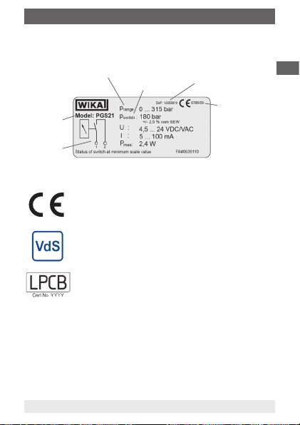
Product label
Prange ... scale range
Model
Pin
assignment
Explanation of symbols
CE, Communauté Européenne
Instruments bearing this mark comply with the relevant
European directives.
Instruments bearing this mark are recognised by the VdS.
Instruments bearing this mark are recognised by the LPCB.
11581752.02 09/2013 GB/D/F/E
WIKA operating instructions models PGS10, PGS11 and PGS21
P
switch ... switch point
Reference number of the
declaration of performance
Identication number
of the product
certication body
including year of the
rst CE marking
GB
7
Page 8
3. Specications
3. Specications
Models PGS10, PGS11 and PGS21
GB
Pressure limitation
- Steady 3/4 x full scale value
- Fluctuating 2/3 x full scale value
- Short time Full scale value
Temperature eect When the temperature of the measuring system
Ingress protection
- Enclosing case per EN 60529 / IEC 529
Operating temperature
- Ambient -20 ... +60 °C
- Medium Maximum +60 °C
For further specications see data sheet PV 20.01, PV 21.01, PV 21.02,
SP 21.01, SP 21.03 and the order documentation.
8
deviates from the reference temperature (+20 °C):
max. ±0.4 %/10 K of the span
Model PGS10 and PGS11: IP 41
(for PGS11.040 with VdS: IP 54)
Model PGS21: IP 65
WIKA operating instructions models PGS10, PGS11 and PGS21
11581752.02 09/2013 GB/D/F/E
Page 9

4. Design and function / 5. Electrical switch contacts
4. Design and function
Description
Bourdon tube measuring elements are widely used in technical pressure
measurement due to their robustness and ease-of-use. Under the inuence
of pressure, these measuring elements deform within their elastic limits.
This motion is converted, via a mechanical movement (toothed gear), into
a rotational motion. To this, an electrical limit switch is connected - the
magnetic snap-action contact. The contact closes or opens the connected
electrical circuits when the settable limit values are exceeded.
Scope of delivery
Cross-check scope of delivery with delivery note.
5. Electrical switch contacts
Electrical connection
■
The electrical connection must only be made by qualied skilled
personnel
■
Connection of the switches via cable or via screw terminals in the
terminal box (L-connector)
■
The terminal assignment is stated on the product label of the pressure
gauge
■
The gauges must be connected to the equipotential bonding of the plant
Electromagnetic compatibility
EMC per EN 60947-5-2.
The instruments are to be protected against strong electromagnetic elds.
11581752.02 09/2013 GB/D/F/E
WIKA operating instructions models PGS10, PGS11 and PGS21
GB
9
Page 10
5. Electrical switch contacts
Flying leads
Single contact Double contact
GB
red: U
black: SP 1 orange: SP 1
Electrical connection via connector (NS 50, 63)
If the IP ingress protection of the connector is lower than that of the
pressure gauge, then this determines the overall ingress protection of the
instrument.
10
+ red: UB+ (common)
B
black: SP 2
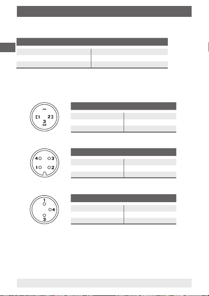
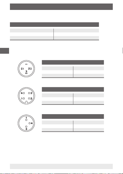
Angular connector EN 175301-803-C
Single contact Double contact
1: U
+ 1: UB+ (common)
B
2: SP 1 2: SP 1
3: SP 2
Circular connector M12 x 1
Single contact Double contact
1: U
+ 1: UB+ (common)
B
4: SP 1 4: SP 1
2: SP 2
Circular connector M8 x 1
Single contact Double contact
1: U
+ 1: UB+ (common)
B
4: SP 1 4: SP 1
WIKA operating instructions models PGS10, PGS11 and PGS21
3: SP 2
11581752.02 09/2013 GB/D/F/E
Page 11
5. Electrical switch contacts
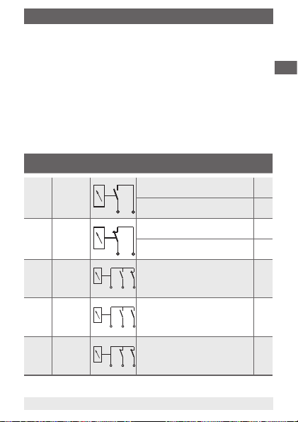
Magnetic snap-action contact (normally closed or normally open)
The instruments are delivered with a single or double contact (normally
closed or normally open).
With 'normally closed', the contact ag is engaged with the limit switch and,
on rising pressure, disengages from the contact via the actuator attached to
the pointer. The circuit will be interrupted.
With 'normally open' the contact ag follows the pointer until the limit value
is reached. Once the limit value has been exceeded, the contact ag
engages and the circuit is closed.
The switching function of the switch is indicated by the index 1, 2, 12, 11
or 22.
Index Designa-
1 Normally
2 Normally
12 Normally
11 Normally
22 Normally
11581752.02 09/2013 GB/D/F/E
WIKA operating instructions models PGS10, PGS11 and PGS21
Symbol Switching function / setting
tion
open
(NO)
closed
(NC)
open /
closed
(NO-NC)
open /
open
(NO-NO)
closed /
closed
(NC-NC)
direction
Contact makes with rising pressure or
clockwise pointer motion (standard)
Contact breaks with falling pressure or
anticlockwise pointer motion
Contact breaks with rising pressure or
clockwise pointer motion (standard)
Contact makes with falling pressure or
anticlockwise pointer motion
See switching function or setting
direction for single contact
See switching function or setting
direction for single contact
See switching function or setting
direction for single contact
GB
Code
1
5
2
4
11
Page 12
5. Electrical switch contacts / 6. Transport, packaging ...
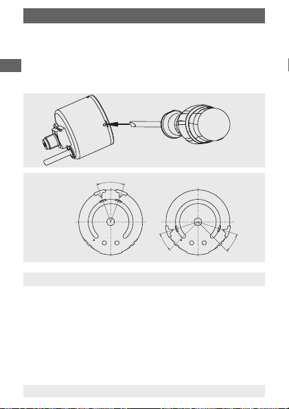
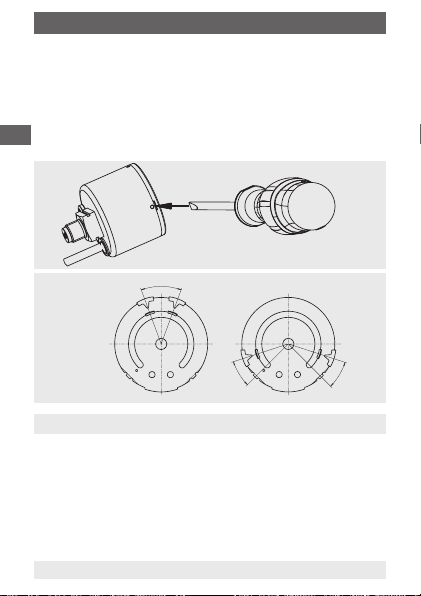
Switch point adjustment (models PGS10 and PGS11)
To adjust the switch point, carefully loosen the window using a screwdriver.
The contact (red mark pointer) can then be set to the desired position by
GB
hand. It can be set between 10 % and 90 % of the full scale value.
Afterwards, lightly push the window back into the case.
If the switch point of the instruments approved by VdS is changed
by the customer, the customer will lose the VdS approval.
Adjustability of
contacts
15 % FSV
10 % FSV
6. Transport, packaging and storage
6.1 Transport
Check pressure gauge for any damage that may have been caused by
transport.
Obvious damage must be reported immediately.
6.2 Packaging
Do not remove packaging until just before mounting.
Keep the packaging as it will provide optimum protection during transport
(e.g. change in installation site, sending for repair).
12
WIKA operating instructions models PGS10, PGS11 and PGS21
31023461.01
10 % FSV
11581752.02 09/2013 GB/D/F/E
Page 13
6. Transport, packaging ... / 7. Commissioning, operation
6.3 Storage
Permissible conditions at the place of storage:
Storage temperature: -20 ... +70 °C
7. Commissioning, operation
Mechanical connection
In accordance with the general technical regulations for pressure gauges
(e.g. EN 837-2 "Selection and installation recommendations for pressure
gauges").
If the pressure gauge is mounted lower than the pressure tapping, the
capillary must be ushed thoroughly before connection in order to clear out
any foreign matter.
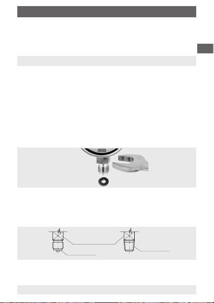
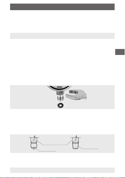
When screwing gauges in, the force required for this must not be applied
through the case, but rather through the spanner ats (using a suitable tool)
provided for this purpose on the square shaft of standard connections.
Installation with
spanner
Correct sealing of pressure gauge connections with parallel threads must
be made using suitable sealing rings, sealing washers or WIKA prole seals.
The sealing of tapered threads (e.g. NPT threads) is made by providing the
thread
, with additional sealing material such as, for example, PTFE tape
(EN 837-2).
GB
Wrench surface
Sealing face
The torque depends on the seal used. Connecting the gauge using a clamp
socket or a union nut is recommended, so that it is easier to orientate the
11581752.02 09/2013 GB/D/F/E
gauge correctly.
WIKA operating instructions models PGS10, PGS11 and PGS21
Sealing in the
thread
13
Page 14
7. Commissioning, operation
Requirements for the installation point
If the measuring point is not adequately stable a measuring instrument
support such as a bracket or ange should be used for fastening (and
GB
possibly via a exible capillary line). If the pressure gauge is exposed to
vibration or pulsating pressure or both, then a liquid lled pressure gauge
may provide considerably better performance and readability. Instruments
should be protected against coarse dirt and wide uctuations in ambient
temperature.
Installation
■
Nominal position per EN 837-1 / 9.6.7 Figure 9: 90° ( ⊥ )
■
Process connection bottom or rear!
■
In order to avoid any additional heating, the instruments must not be
exposed to direct solar irradiation while in operation!
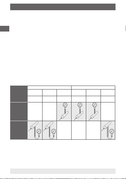
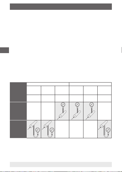
Measuring assemblies
Proven measuring assemblies for various types of media.
liquid media gaseous media
Filling of the
capillary
Examples
Pressure
gauge above
the tapping
point
Pressure
gauge below
the tapping
point
Admissible ambient and working temperatures
When mounting the pressure gauge it must be ensured that, taking into
consideration the inuence of convection and heat radiation, no deviation
above or below the permissible ambient and medium temperatures can
occur. The inuence of temperature on the display accuracy must be
observed.
14
liquid with
liquid
condensate boiling liquid
vapour only gaseous wet gas
vapour
"liqueed
gases"
dry air
moist air, ue
gases
WIKA operating instructions models PGS10, PGS11 and PGS21
liquid gas
condensate
Steam
11581752.02 09/2013 GB/D/F/E
Page 15

7. Commissioning, operation / 8. Maintenance and cleaning
Permissible vibration load at the installation site
■
The instruments should always be installed in locations free from
vibration.
■
If the pipe to the gauge is not rigid enough for a vibration-free
installation, the gauge should be mounted by means of mounting
devices for surface or pipe mounting, and, if necessary, with a capillary.
■
If necessary, it is possible to isolate the instrument from the mounting
point by installing a exible connection line between the measuring
point and the pressure gauge and mounting the instrument on a suitable
bracket.
■
If this is not possible, the following limit values must not be exceeded:
Frequency range < 150 Hz
Acceleration < 0.5 g (5 m/s
2
)
Commissioning
During the commissioning process pressure surges must be avoided at all
costs. Open the shut-o valves slowly.
8. Maintenance and cleaning
8.1 Maintenance
■
The instruments are maintenance-free.
■
The indicator and switching function should be checked once or twice
every year. The gauge must be disconnected from the process to check
with a pressure testing device.
■
Repairs are only to be carried out by the manufacturer or appropriately
trained skilled personnel.
11581752.02 09/2013 GB/D/F/E
WIKA operating instructions models PGS10, PGS11 and PGS21
GB
15
Page 16
8. Maintenance and cleaning / 9. Dismounting and disposal
8.2 Cleaning
CAUTION!
GB
■
Before cleaning, correctly disconnect the pressure gauge
from the pressure supply, switch it o and disconnect it
from the mains.
■
Clean the instrument with a moist cloth.
■
Electrical connections must not come into contact with
moisture.
■
Wash or clean the dismounted instrument before
returning it, in order to protect persons and the
environment from exposure to residual media.
9. Dismounting and disposal
WARNING!
Residual media in dismounted pressure gauges may result
in a risk to people, the environment and the system. Take
sucient precautionary measures.
9.1 Dismounting
Only disconnect the pressure gauge once the system has been depressurised!
9.2 Disposal
Incorrect disposal may endanger the environment.
Dispose of instrument components and packaging materials in an environ-
mentally compatible way and in accordance with the country-specic waste
disposal regulations.
16
WIKA operating instructions models PGS10, PGS11 and PGS21
11581752.02 09/2013 GB/D/F/E
Page 17
WIKA Alexander Wiegand SE & Co. KG
Germany
Peter Koll
Daniel Kotlewski
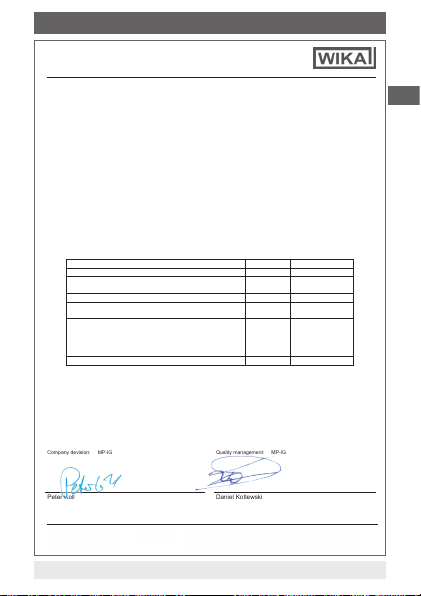
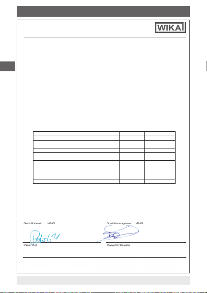
Appendix 1: Declaration of performance model PGS11.040
DECLARATION OF PERFORMANCE
according Construction Performance Regulation EU Nr. 305/2011
Tel. +49 9372 132-0
Fax +49 9372 132-406
E-Mail info@wika.de
www.wika.de
Document No.: 14059917.02
Kommanditgesellschaft: Sitz Klingenberg –
Amtsgericht Aschaffenburg HRA 1819
Komplementärin: WIKA Verwaltungs SE & Co. KG –
Sitz Klingenberg –Amtsgericht Aschaffenburg
HRA 4685
as part of e complete operating system.
ued following certificate of certificate of
pass
pass
pass
pass
1. Identification: pressure gauge with switch
2. Model: PGS11.040 according to data sheet SP 21.01
3. Intended use according EN 12094-10: 2003
Components for use in gas extinguishing systems in buildings
4. Manufacturer:
WIKA Alexander Wiegand SE & Co.KG
Alexander-Wiegand-Str. 30, DE 63911 Klingenberg
5. Representative: Not applicable
6. Assessment: System 1
7. Notified body:
VdS Schadenverhütung GmbH, 0786 has performed type testing of the product, initial inspection of the
manufacturing plant and of factory production control with continuous surveillance, assessment and
evaluation of factory production control under system 1 and iss
conformity 0786-CPD-30089.
8. European Technical Assessment: Not applicable
9. Declared performance:
Essential Characteristics Performance EN 12094-10:2003
Operational reliability -- general pass 4.1.1
Nominal activation conditions/sensitivity
- accuracy class and nominal size pass 4.1.2
Durability of operational reliability against - corrosion pass 4.1.3
Nominal activation conditions/sensitivity
- accuracy class and nominal size pass 4.2.1
Operational reliability
- Design
- Internal pressure
- Operational reliability
- Temperature
Durability of operational reliability against - corrosion pass 4.2.6
10. The performance of the product identified in points 1 and 2 is in conformity with the declared performance in point
9. This declaration of performance is issued under the sole responsibility of the manufacturer identified in point 4.
Signed for and on behalf of
WIKA Alexander Wiegand SE & Co. KG
Klingenberg, 2013-08-02
Company devision: MP-IG Quality management: MP-IG
Signature authorized by the company
Alexander-Wiegand-Straße 30
63911 Klingenberg
11581752.02 09/2013 GB/D/F/E
WIKA operating instructions models PGS10, PGS11 and PGS21
4.2.2
4.2.3
4.2.4
4.2.5
Komplementärin:
WIKA International SE -Sitz Klingenberg Amtsgericht Aschaffenburg HRB 10505
Vorstand: Alexander Wiegand
Vorsitzender des Aufsichtsrats: Dr. Max Egli
GB
17
Page 18
Tel. +49 9372 132-0
www.wika.de
Vorsitzender des Aufsichtsrats: Dr. Max Egli
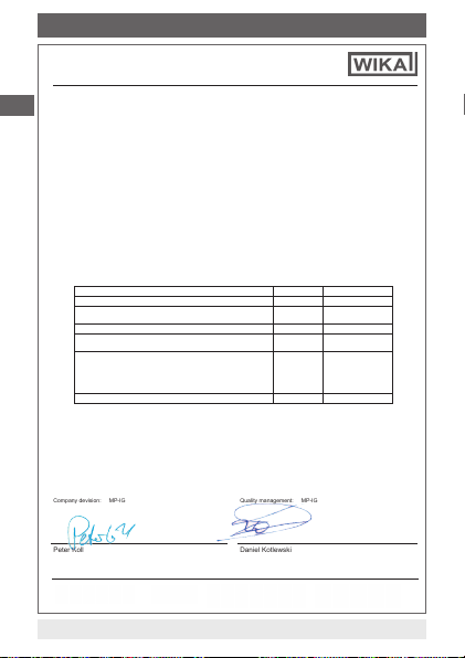
Appendix 2: Declaration of performance model PGS21.050
GB
1. Identification: pressure gauge with switch
2. Model: PGS21.050 according to data sheet SP 21.03
3. Intended use according EN 12094-10: 2003
Components for use in gas extinguishing systems in buildings as part of e complete operating system.
4. Manufacturer:
WIKA Alexander Wiegand SE & Co.KG
Alexander-Wiegand-Str. 30, DE 63911 Klingenberg
5. Representative: N
6. Assessment: System 1
7. Notified body:
VdS Schadenverhütung GmbH, 0786 has performed type testing of the product, initial inspection of the
manufacturing plant and of factory production control with continuous surveillance, assessment and
evaluation of factory production control under system 1 and issued following certificate of certificate of
conformity 0786-CPD-30095.
8. European Technical Assessment: Not applicable
9. Declared performance:
Essential Char
Operational reliability -- general pass 4.1.1
Nominal activation conditions/sensitivity
- accuracy class and nominal size pass 4.1.2
Durability of operational reliability against - corrosion pass 4.1.3
Nominal activation conditions/sensitivity
- accuracy class and nominal size pass 4.2.1
Operational reliability
- Design
- Internal pressure
- Operational reliability
- Temperature
Durability of operational reliability against - corrosion pass 4.2.6
10. The performance of the product identified in points 1 and 2 is in conformity with the declared performance in point
9. This declaration of performance is issued under the sole responsibility of the manufacturer identified in point 4.
Signed for and on behalf of
WIKA Alexander Wiegand SE & Co. KG
Klingenberg, 2013-08-02
Company devision: MP-IG Quality management: MP-IG
Peter Koll Daniel Kotlewski
Signature authorized by the company
WIKA Alexander Wiegand SE & Co. KG
Alexander-Wiegand-Straße 30
63911 Klingenberg
Germany
18
DECLARATION OF PERFORMANCE
according Construction Performance Regulation EU Nr. 305/2011
Document No.: 14059919.02
ot applicable
acteristics Performance EN 12094-10:2003
pass
pass
pass
pass
Kommanditgesellschaft: Sitz Klingenberg –
Amtsgericht Aschaffenburg HRA 1819
Fax +49 9372 132-406
Komplementärin: WIKA Verwaltungs SE & Co. KG –
E-Mail info@wika.de
Sitz Klingenberg –Amtsgericht Aschaffenburg
HRA 4685
WIKA operating instructions models PGS10, PGS11 and PGS21
4.2.2
4.2.3
4.2.4
4.2.5
Komplementärin:
WIKA International SE -Sitz Klingenberg Amtsgericht Aschaffenburg HRB 10505
Vorstand: Alexander Wiegand
11581752.02 09/2013 GB/D/F/E
Page 19

Inhalt
Inhalt
1. Allgemeines
2. Sicherheit
3. Technische Daten
4. Aufbau und Funktion
5. Elektrische Schaltkontakte
6. Transport, Verpackung und Lagerung
7. Inbetriebnahme, Betrieb
8. Wartung und Reinigung
9. Demontage und Entsorgung
Anlage 1: Leistungserklärung Typ PGS11.040
Anlage 2: Leistungserklärung Typ PGS21.050
11581752.02 09/2013 GB/D/F/E
WIKA Betriebsanleitung Typen PGS10, PGS11 und PGS21
20
D
21
24
25
25
28
29
31
32
33
34
19
Page 20

1. Allgemeines
1. Allgemeines
■
Das in der Betriebsanleitung beschriebene Druckmessgerät wird nach
dem aktuellen Stand der Technik konstruiert und gefertigt.
Alle Komponenten unterliegen während der Fertigung strengen
Qualitäts- und Umweltkriterien. Unsere Managementsysteme sind nach
D
ISO 9001 und ISO 14001 zertiziert.
■
Diese Betriebsanleitung gibt wichtige Hinweise zum Umgang mit dem
Gerät. Voraussetzung für sicheres Arbeiten ist die Einhaltung aller
angegebenen Sicherheitshinweise und Handlungsanweisungen.
■
Die für den Einsatzbereich des Gerätes geltenden örtlichen Unfallverhütungsvorschriften und allgemeinen Sicherheitsbestimmungen
einhalten.
■
Die Betriebsanleitung ist Produktbestandteil und muss in unmittelbarer
Nähe des Gerätes für das Fachpersonal jederzeit zugänglich
aufbewahrt werden.
■
Das Fachpersonal muss die Betriebsanleitung vor Beginn aller Arbeiten
sorgfältig durchgelesen und verstanden haben.
■
Die Haftung des Herstellers erlischt bei Schäden durch bestimmungswidrige Verwendung, Nichtbeachten dieser Betriebsanleitung, Einsatz
ungenügend qualizierten Fachpersonals sowie eigenmächtiger
Veränderung am Gerät.
■
Es gelten die allgemeinen Geschäftsbedingungen in den
Verkaufsunterlagen.
■
Technische Änderungen vorbehalten.
■
Weitere Informationen:
- Internet-Adresse: www.wika.de / www.wika.com
- zugehöriges Datenblatt: PV 20.01, PV 21.01, PV 21.02,
20
WIKA Betriebsanleitung Typen PGS10, PGS11 und PGS21
SP 21.01 und SP 21.03
11581752.02 09/2013 GB/D/F/E
Page 21
1. Allgemeines / 2. Sicherheit
Symbolerklärung
WARNUNG!
… weist auf eine möglicherweise gefährliche Situation hin,
die zum Tod oder zu schweren Verletzungen führen kann,
wenn sie nicht gemieden wird.
Information
… hebt nützliche Tipps und Empfehlungen sowie
Informationen für einen ezienten und störungsfreien Betrieb
hervor.
2. Sicherheit
WARNUNG!
Vor Montage, Inbetriebnahme und Betrieb sicherstellen,
dass das richtige Druckmessgerät hinsichtlich Messbereich,
Ausführung und spezischen Messbedingungen ausgewählt
wurde.
Die Belastungsgrenzen sind einzuhalten, um die
Messgenauigkeit und die Lebensdauer zu gewährleisten.
Alle Arbeiten dürfen nur im spannungslosen Zustand
erfolgen.
Bei Nichtbeachten können schwere Körperverletzungen und/
oder Sachschäden auftreten.
Weitere wichtige Sicherheitshinweise benden sich in den
einzelnen Kapiteln dieser Betriebsanleitung.
2.1 Bestimmungsgemäße Verwendung
Die Druckmessgeräte mit Schaltkontakten switchGAUGE Typen
PGS10, PGS11 und PGS21 dienen zum Steuern und Regeln von
Industrieprozessen, zur Anlagenüberwachung und zum Schalten von
Stromkreisen.
Das Gerät ist ausschließlich für den hier beschriebenen bestimmungs-
11581752.02 09/2013 GB/D/F/E
WIKA Betriebsanleitung Typen PGS10, PGS11 und PGS21
D
21
Page 22

2. Sicherheit
gemäßen Verwendungszweck konzipiert und konstruiert und darf nur
dementsprechend verwendet werden.
Ansprüche jeglicher Art aufgrund von nicht bestimmungsgemäßer
Verwendung sind ausgeschlossen.
D
2.2 Personalqualikation
WARNUNG!
Verletzungsgefahr bei unzureichender Qualikation!
Unsachgemäßer Umgang kann zu erheblichen Personenund Sachschäden führen.
■ Die in dieser Betriebsanleitung beschriebenen Tätigkeiten
nur durch Fachpersonal nachfolgend beschriebener
Qualikation durchführen lassen.
Fachpersonal
Das Fachpersonal ist aufgrund seiner fachlichen Ausbildung, seiner
Kenntnisse der Mess- und Regelungstechnik und seiner Erfahrungen
sowie Kenntnis der landesspezischen Vorschriften, geltenden Normen
und Richtlinien in der Lage, die beschriebenen Arbeiten auszuführen und
mögliche Gefahren selbstständig zu erkennen.
2.3 Besondere Gefahren
WARNUNG!
Bei gefährlichen Messstoen wie z. B. Sauersto, Acetylen,
brennbaren oder giftigen Stoen, sowie bei Kälteanlagen,
Kompressoren etc. müssen über die gesamten allgemeinen
Regeln hinaus die jeweils bestehenden einschlägigen
Vorschriften beachtet werden.
WARNUNG!
Messstoreste in ausgebauten Druckmessgeräten können
zur Gefährdung von Personen, Umwelt und Einrichtung
führen.
Ausreichende Vorsichtsmaßnahmen ergreifen.
22
WIKA Betriebsanleitung Typen PGS10, PGS11 und PGS21
11581752.02 09/2013 GB/D/F/E
Page 23

2. Sicherheit
2.4 Beschilderung / Sicherheitskennzeichnungen
Typenschild
Prange ... Anzeigebereich
Typ
Anschlussbelegung
Symbolerklärung
CE, Communauté Européenne
Geräte mit dieser Kennzeichnung stimmen überein mit den
zutreenden europäischen Richtlinien.
Geräte mit dieser Kennzeichnung sind vom VdS
anerkannt.
Geräte mit dieser Kennzeichnung sind vom LPCB
anerkannt.
11581752.02 09/2013 GB/D/F/E
WIKA Betriebsanleitung Typen PGS10, PGS11 und PGS21
P
switch ... Schaltpunkt
Bezugsnummer der
Leistungserklärung
Kennnummer der
Produktzertizierungsstelle mit Jahr
der ersten CEKennzeichnung
D
23
Page 24

3. Technische Daten
3. Technische Daten
Typen PGS10, PGS11 und PGS21
Druckbelastbarkeit
- Ruhebelastung 3/4 x Skalenendwert
- Wechselbelastung 2/3 x Skalenendwert
D
- Kurzzeitig Skalenendwert
Temperatureinuss Bei Abweichung von der Referenztemperatur am Messsy-
Schutzart
- Umhüllendes Gehäuse nach EN 60529 / IEC 529
Zulässige Temperatur
- Umgebung -20 ... +60 °C
- Messsto Maximal +60 °C
Weitere technische Daten siehe Datenblatt PV 20.01, PV 21.01, PV 21.02,
SP 21.01, SP 21.03 und Bestellunterlagen.
24
stem (+20 °C): max. ± 0,4 %/10 K von der Anzeigespanne
Typ PGS10 und PGS11: IP 41
(bei PGS11.040 mit VdS: IP 54)
Typ PGS21: IP 65
WIKA Betriebsanleitung Typen PGS10, PGS11 und PGS21
11581752.02 09/2013 GB/D/F/E
Page 25

4. Aufbau und Funktion / 5. Elektrische Schaltkontakte
4. Aufbau und Funktion
Beschreibung
Als Messelement werden die in der technischen Druckmesstechnik wegen
ihrer Robustheit und einfachen Handhabung weit verbreiteten Rohrfeder-
Messglieder verwendet. Unter dem Einuss des Drucks verformen sich
diese Messglieder im elastischen Bereich.
Diese Bewegung wird über ein mechanisches Messwerk (Zahnräder) in
eine Drehbewegung umgesetzt. Zu dem ist ein elektrischer Grenzwertschalter eingebaut, der sogenannte Magnetspringkontakt. Der Kontakt
schließt oder önet die angeschlossenen Stromkreise bei Überschreiten
der einstellbaren Grenzwerte.
Lieferumfang
Lieferumfang mit dem Lieferschein abgleichen.
5. Elektrische Schaltkontakte
Elektrischer Anschluss
■
Der elektrische Anschluss darf nur durch qualiziertes Fachpersonal
erfolgen
■
Anschluss der Schalter über Kabel oder über Schraubklemmen in der
Kabeldose (Winkelstecker)
■
Klemmenbelegung auf Typenschild am Druckmessgerät
■
Die Geräte sind in den Potenzialausgleich der Anlage mit einzubeziehen
Elektromagnetische Verträglichkeit
EMV gemäß EN 60947-5-2.
Die Geräte sind vor starken elektromagnetischen Feldern zu schützen.
11581752.02 09/2013 GB/D/F/E
WIKA Betriebsanleitung Typen PGS10, PGS11 und PGS21
D
25
Page 26

5. Elektrische Schaltkontakte
Kabelausgang
Einzelkontakt Doppelkontakt
rot: U
schwarz: SP 1 orange: SP 1
D
Elektrischer Anschluss über Stecker (NG 50, 63)
Wenn die IP-Schutzart des Steckverbinders kleiner ist als die des Druckmessgerätes, bestimmt diese die Gesamtschutzart des Gerätes.
26
+ rot: UB+ (common)
B
schwarz: SP 2
Winkelstecker EN 175301-803-C
Einzelkontakt Doppelkontakt
1: U
+ 1: UB+ (common)
B
2: SP 1 2: SP 1
Rundsteckverbinder M12 x 1
Einzelkontakt Doppelkontakt
1: U
+ 1: UB+ (common)
B
4: SP 1 4: SP 1
Rundsteckverbinder M8 x 1
Einzelkontakt Doppelkontakt
1: U
+ 1: UB+ (common)
B
4: SP 1 4: SP 1
WIKA Betriebsanleitung Typen PGS10, PGS11 und PGS21
3: SP 2
2: SP 2
3: SP 2
11581752.02 09/2013 GB/D/F/E
Page 27

5. Elektrische Schaltkontakte
Magnetspringkontakt (Öner oder Schließer)
Die Geräte werden mit einem Einfach- oder Doppelkontakt (Öner oder
Schließer) ausgeliefert.
Bei einem Öner liegt die Kontaktfahne an dem Grenzwertschalter an und
wird durch den am Zeiger angebrachten Mitnehmer, bei steigendem Druck,
vom Kontakt gelöst. Der Stromkreis wird unterbrochen.
Bei einem Schließer folgt die Kontaktfahne dem Zeiger nach, bis der Grenz-
wertschalter erreicht ist. Nach Überschreiten des Grenzwertschalters liegt
die Kontaktfahne an und der Stromkreis ist geschlossen.
Die Schaltfunktion des Schalters wird durch die Kennzahl 1, 2, 12, 11 oder
22 angegeben.
Kenn-
Bezeich-
zahl
1 Schließer
2 Öner
12 Schließer-
11 Schließer-
22 Öner-
11581752.02 09/2013 GB/D/F/E
WIKA Betriebsanleitung Typen PGS10, PGS11 und PGS21
Symbol Schaltfunktion / Einstellrichtung Code
nung
Kontakt schließt bei steigendem Druck
(NO)
(NC)
Öner
(NO-NC)
Schließer
(NO-NO)
Öner
(NC-NC)
bzw. Zeigerbewegung im Uhrzeigersinn
(Standard)
Kontakt önet bei fallendem Druck
bzw. Zeigerbewegung gegen den
Uhrzeigersinn
Kontakt önet bei steigendem Druck
bzw. Zeigerbewegung im Uhrzeigersinn
(Standard)
Kontakt schließt bei fallendem Druck
bzw. Zeigerbewegung gegen den
Uhrzeigersinn
Siehe Schaltfunktion bzw.
Einstellrichtung bei Einzelkontakt
Siehe Schaltfunktion bzw.
Einstellrichtung bei Einzelkontakt
Siehe Schaltfunktion bzw.
Einstellrichtung bei Einzelkontakt
D
1
5
2
4
27
Page 28
5. Elektrische Schaltkontakte / 6. Transport, Verpackung ...
Schaltpunktverstellung (Typen PGS10 und PGS11)
Zur Verstellung des Schaltpunktes die Sichtscheibe mit einem Schraubendreher vorsichtig lösen. Der Kontakt (roter Markenzeiger) kann daraufhin
per Hand auf die gewünschte Position gestellt werden. Er ist zwischen 10 %
und 90 % vom Skalenendwert verstellbar.
Sichtscheibe anschließend unter leichtem Druck wieder ins Gehäuse
D
drücken.
Wird bei VdS zugelassenen Geräten der Schaltpunkt vom
Kunden verstellt, so geht die VdS-Zulassung verloren.
Einstellbarkeit
der Kontakte
15 % SEW
10 % SEW
6. Transport, Verpackung und Lagerung
6.1 Transport
Druckmessgerät auf eventuell vorhandene Transportschäden untersuchen.
Oensichtliche Schäden unverzüglich mitteilen.
6.2 Verpackung
Verpackung erst unmittelbar vor der Montage entfernen.
Die Verpackung aufbewahren, denn diese bietet bei einem Transport einen
optimalen Schutz (z. B. wechselnder Einbauort, Reparatursendung).
28
WIKA Betriebsanleitung Typen PGS10, PGS11 und PGS21
31023461.01
10 % SEW
11581752.02 09/2013 GB/D/F/E
Page 29

6. Transport, Verpackung ... / 7. Inbetriebnahme, Betrieb
6.3 Lagerung
Zulässige Bedingungen am Lagerort
Lagertemperatur: -20 ... +70 °C
7. Inbetriebnahme, Betrieb
Mechanischer Anschluss
Entsprechend den allgemeinen technischen Regeln für Druckmessgeräte
(z. B. EN 837-2 "Auswahl- und Einbauempfehlungen für Druckmessgeräte").
Ist das Druckmessgerät tiefer als der Druckentnahmestutzen angeordnet,
muss die Messleitung vor dem Anschließen gut durchgespült werden, um
Fremdkörper zu beseitigen.
Beim Einschrauben der Geräte darf die zum Abdichten erforderliche Kraft
nicht über das Gehäuse oder die Kabelanschlussdose aufgebracht werden,
sondern mit geeignetem Werkzeug nur über die dafür vorgesehenen
Schlüsselächen am Vierkant des Anschlusszapfens.
Montage mit
Gabelschlüssel
D
Zur Abdichtung der Druckmessgeräteanschlüsse mit zylindrischem
Gewinde an der Dichtäche
WIKA-Proldichtungen einzusetzen. Bei kegeligem Gewinde (z. B.
NPT-Gewinde) erfolgt die Abdichtung im Gewinde
Dichtwerkstoen, wie z. B. PTFE-Band (EN 837-2).
Das Anzugsmoment ist von der eingesetzten Dichtung abhängig. Um das
Messgerät in die Stellung zu bringen, in der es sich am besten ablesen
11581752.02 09/2013 GB/D/F/E
lässt, ist ein Anschluss mit Spannmue oder Überwurfmutter zu empfehlen.
WIKA Betriebsanleitung Typen PGS10, PGS11 und PGS21
sind Flachdichtungen, Dichtlinsen oder
Schlüsseläche
Dichtäche
, mit zusätzlichen
Abdichtung im
Gewinde
29
Page 30

7. Inbetriebnahme, Betrieb
Anforderungen an die Einbaustelle
Ist die Leitung zum Messgerät für eine erschütterungsfreie Anbringung nicht
stabil genug, sollte (evtl. über eine exible Kapillarleitung) die Befestigung
mittels Messgerätehalterung erfolgen. Können Erschütterungen nicht durch
geeignete Installationen vermieden werden, sollten Geräte mit Flüssigkeitsfüllung eingesetzt werden. Die Geräte sind vor grober Verschmutzung und
D
starken Schwankungen der Umgebungstemperatur zu schützen.
Installation
■
Nennlage nach EN 837-1 / 9.6.7 Bild 9: 90° ( ⊥ )
■
Prozessanschluss unten bzw. rückseitig!
■
Um zusätzliche Aufheizung zu vermeiden, dürfen die Geräte im Betrieb
keiner direkten Sonneneinstrahlung ausgesetzt werden!
Messanordnungen
Bewährte Messanordnungen für verschiedene Messstoarten.
üssige Messstoe gasförmige Messstoe
Füllung der
Messleitung
Beispiele
Druckmessgerät
oberhalb des
Entnahmestutzens
Druckmessgerät
unterhalb des
Entnahmestutzens
üssig
Kondensat
zum Teil
ausgasend
siedende
Flüssigkeiten
vollständig
verdampft
„Flüssiggase“ trockene Luft
Zulässige Umgebungs- und Betriebstemperaturen
Die Anbringung des Druckmessgerätes ist so auszuführen, dass die
zulässigen Umgebungs- und Messstotemperaturgrenzen, auch unter
Berücksichtigung des Einusses von Konvektion und Wärmestrahlung,
weder unter- noch überschritten werden. Der Temperatureinuss auf die
Anzeigegenauigkeit ist zu beachten.
30
WIKA Betriebsanleitung Typen PGS10, PGS11 und PGS21
gasförmig
z. T. kondensiert feucht)
feuchte Luft,
Rauchgase
vollständig
kondensiert
Wasserdampf
11581752.02 09/2013 GB/D/F/E
Page 31

7. Inbetriebnahme, Betrieb / 8. Wartung und Reinigung
Zulässige Schwingungsbelastung am Einbauort
■
Die Geräte sollten grundsätzlich nur an Stellen ohne
Schwingungsbelastung eingebaut werden
■
Ist die Leitung zum Druckmessgerät für eine erschütterungsfreie
Anbringung nicht stabil genug, so ist die Befestigung über
entsprechende Befestigungselemente für Wand- und/oder
Rohrmontage, ggf. über eine Kapillarleitung vorzunehmen.
■
Gegebenenfalls kann z. B. durch eine exible Verbindungsleitung von
der Messstelle zum Druckmessgerät und die Befestigung über eine
Messgerätehalterung eine Entkopplung vom Einbauort erreicht werden.
■
Falls dies nicht möglich ist, dürfen folgende Grenzwerte nicht
überschritten werden:
Frequenzbereich < 150 Hz
Beschleunigung < 0,5 g (5 m/s
2
)
Inbetriebnahme
Bei Inbetriebnahme Druckstöße unbedingt vermeiden, Absperrventile
langsam önen.
8. Wartung und Reinigung
8.1 Wartung
■
Die Geräte sind wartungsfrei.
■
Eine Überprüfung der Anzeige und der Schaltfunktion sollte etwa 1 bis
2 Mal pro Jahr erfolgen. Dazu ist das Gerät vom Prozess zu trennen und
mit einer Druckprüfvorrichtung zu kontrollieren.
■
Reparaturen sind ausschließlich vom Hersteller oder entsprechend
qualiziertem Fachpersonal durchzuführen.
11581752.02 09/2013 GB/D/F/E
WIKA Betriebsanleitung Typen PGS10, PGS11 und PGS21
D
31
Page 32

8. Wartung und Reinigung / 9. Demontage und Entsorgung
8.2 Reinigung
VORSICHT!
■
Vor der Reinigung das Druckmessgerät ordnungsgemäß
von der Druckversorgung trennen, ausschalten und vom
D
Netz trennen.
■
Das Gerät mit einem feuchten Tuch reinigen.
■
Elektrische Anschlüsse nicht mit Feuchtigkeit in
Berührung bringen.
■
Ausgebautes Gerät vor der Rücksendung spülen bzw.
säubern, um Personen und Umwelt vor Gefährdung
durch anhaftende Messstoreste zu schützen.
9. Demontage und Entsorgung
WARNUNG!
Messstoreste in ausgebauten Druckmessgeräten können
zur Gefährdung von Personen, Umwelt und Einrichtung
führen.
Ausreichende Vorsichtsmaßnahmen ergreifen.
9.1 Demontage
Druckmessgerät nur im drucklosen Zustand demontieren!
9.2 Entsorgung
Durch falsche Entsorgung können Gefahren für die Umwelt entstehen.
Gerätekomponenten und Verpackungsmaterialien entsprechend den
landesspezischen Abfallbehandlungs- und Entsorgungsvorschriften
umweltgerecht entsorgen.
32
WIKA Betriebsanleitung Typen PGS10, PGS11 und PGS21
11581752.02 09/2013 GB/D/F/E
Page 33

Kommanditgesellschaft: Sitz Klingenberg –
HRA 4685
Geschäftsbereich: MP-IG
Qualitätsmanagement: MP-IG
Peter Koll
Daniel Kotlewski
Anlage 1: Leistungserklärung Typ PGS11.040
LEISTUNGSERKLÄRUNG
gemäß Bauprodukteverordnung EU Nr. 305/2011
installiert ist.
Dokument Nr.: 14059917.02
bestanden
bestanden
bestanden
bestanden
4.2.2
4.2.3
4.2.4
4.2.5
1. Beschreibung: Druckmessgerät mit Grenzsignalgeber
2. Typ: PGS11.040 nach Datenblatt SP 21.01
3. Verwendungszweck gemäß EN 12094-10: 2003
Bauteil für die Verwendung in Löschanlagen mit gasförmigen Löschmitteln, das in Gebäuden
als Teil einer Anlage
4. Hersteller:
WIKA Alexander Wiegand SE & Co.KG
Alexander-Wiegand-Str. 30, DE 63911 Klingenberg
5. Bevollmächtigter: Nicht zutreffend
6. Bewertung: System 1
7. Notifizierte Stelle:
VdS Schadenverhütung GmbH, 0786 hat die Typprüfung des Produkts, die Erstinspektion des Werks und
der werkseigenen Produktionskontrolle mit laufender Überwachung, Bewertung und Evaluierung der
werkseigenen Produktionskontrolle unter System 1 durchgeführt und das EG-Konformitätszertifikat 0786C
PD-30089 ausgestellt.
8. Europäische Technische Bewertung: Nicht zutreffend
9. Erklärte Leistung
Wesentliche Merkmale Leistung EN 12094-10:2003
Betriebszuverlässigkeit - Allgemeines bestanden 4.1.1
Nennansprechbedingungen/Annsprechempfindlichkeit
- Genauigkeitsklasse und Nenngröße bestanden 4.1.2
Stabilität der Betriebszuverlässigkeit gegen - Korrosion bestanden 4.1.3
Nennansprechbedingungen/Ansprechempfindlichkeit
- Genauigkeitsklasse und Nenngröße bestanden 4.2.1
Betriebszuverlässigkeit
- Konstruktion
- Innendruck
- Betriebssicherheit
- Temperatur
Stabilität der Betriebszuverlässigkeit gegen -Korrosion bestanden 4.2.6
10. Die Leistung des Produkts gemäß den Nummern 1 und 2 entspricht der erklärten Leistung nach Nummer 9.
Verantwortlich für die Erstellung dieser Leistungserklärung ist allein der Hersteller gemäß Nummer 4.
Unterzeichnet für und im Namen von
WIKA Alexander Wiegand SE & Co. KG
Klingenberg, 2013-08-02
D
Unterschrift, autorisiert durch das Unternehmen
WIKA Alexander Wiegand SE & Co. KG
Alexander-Wiegand-Straße 30
63911 Klingenberg
Germany
11581752.02 09/2013 GB/D/F/E
WIKA Betriebsanleitung Typen PGS10, PGS11 und PGS21
Tel. +49 9372 132-0
Fax +49 9372 132-406
E-Mail info@wika.de
www.wika.de
Amtsgericht Aschaffenburg HRA 1819
Komplementärin: WIKA Verwaltungs SE & Co. KG –
Sitz Klingenberg –Amtsgericht Aschaffenburg
Komplementärin:
WIKA International SE -Sitz Klingenberg Amtsgericht Aschaffenburg HRB 10505
Vorstand: Alexander Wiegand
Vorsitzender des Aufsichtsrats: Dr. Max Egli
33
Page 34
HRA 4685
Komplementärin:
Geschäftsbereich: MP-IG
Qualitätsmanagement: MP-IG
Peter Koll
Daniel Kotlewski
Anlage 2: Leistungserklärung Typ PGS21.050
LEISTUNGSERKLÄRUNG
gemäß Bauprodukteverordnung EU Nr. 305/2011
stellt.
Dokument Nr.: 14059919.02
bestanden
bestanden
bestanden
bestanden
1. Beschreibung: Druckmessgerät mit Grenzsignalgeber
D
2. Typ: PGS21.050 nach Datenblatt SP 21.03
3. Verwendungszweck gemäß EN 12094-10: 2003
Bauteil für die Verwendung in Löschanlagen mit gasförmigen Löschmitteln, das in Gebäuden
als Teil einer Anlage installiert ist.
4
. Hersteller:
WIKA Alexander Wiegand SE & Co.KG
Alexander-Wiegand-Str. 30, DE 63911 Klingenberg
5. Bevollmächtigter: Nicht zutreffend
6. Bewertung: System 1
7. Notifizierte Stelle:
VdS Schadenverhütung GmbH, 0786 hat die Typprüfung des Produkts, die Erstinspektion des Werks und
der werkseigenen Produktionskontrolle mit laufender Überwachung, Bewertung und Evaluierung der
werkseigenen Produktionskontrolle unter System 1 durchgeführt und das EG-Konformitätszertifikat 0786CPD-30095 ausge
8. Europäische Technische Bewertung: Nicht zutreffend
9. Erklärte Leistung
Wesentliche Merkmale Leistung EN 12094-10:2003
Betriebszuverlässigkeit - Allgemeines bestanden 4.1.1
Nennansprechbedingungen/Annsprechempfindlichkeit
- Genauigkeitsklasse und Nenngröße bestanden 4.1.2
Stabilität der Betriebszuverlässigkeit gegen - Korrosion bestanden 4.1.3
Nennansprechbedingungen/Ansprechempfindlichkeit
- Genauigkeitsklasse und Nenngröße bestanden 4.2.1
Betriebszuverlässigkeit
- Konstruktion
- Innendruck
- Betriebssicherheit
- Temperatur
Stabilität der Betriebszuverlässigkeit gegen - Korrosion bestanden 4.2.6
10. Die Leistung des Produkts gemäß den Nummern 1 und 2 entspricht der erklärten Leistung nach Nummer 9.
Verantwortlich für die Erstellung dieser Leistungserklärung ist allein der Hersteller gemäß Nummer 4.
Unterzeichnet für und im Namen von
WIKA Alexander Wiegand SE & Co. KG
Klingenberg, 2013-08-02
4.2.2
4.2.3
4.2.4
4.2.5
Unterschrift, autorisiet durch das Unternehmen
WIKA Alexander Wiegand SE & Co. KG
Alexander-Wiegand-Straße 30
63911 Klingenberg
Germany
34
Kommanditgesellschaft: Sitz Klingenberg –
Tel. +49 9372 132-0
Fax +49 9372 132-406
E-Mail info@wika.de
www.wika.de
Amtsgericht Aschaffenburg HRA 1819
Komplementärin: WIKA Verwaltungs SE & Co. KG –
Sitz Klingenberg –Amtsgericht Aschaffenburg
WIKA International SE -Sitz Klingenberg Amtsgericht Aschaffenburg HRB 10505
Vorstand: Alexander Wiegand
Vorsitzender des Aufsichtsrats: Dr. Max Egli
WIKA Betriebsanleitung Typen PGS10, PGS11 und PGS21
11581752.02 09/2013 GB/D/F/E
Page 35

Sommaire
Sommaire
1. Généralités
2. Sécurité
3. Caractéristiques techniques
4. Conception et fonction
5. Contacts électriques
6. Transport, emballage et stockage
7. Mise en service, exploitation
8. Entretien et nettoyage
9. Démontage et mise au rebut
Appendix 1 : Declaration de performance type PGS11.040
Appendix 2 : Declaration de performance type PGS21.050
11581752.02 09/2013 GB/D/F/E
WIKA mode d‘emploi types PGS10, PGS11 et PGS21
36
37
F
40
41
41
44
45
47
48
49
50
35
Page 36

1. Généralités
1. Généralités
■
Le manomètre décrit dans le présent mode d’emploi est conçu
et fabriqué selon les dernières technologies en vigueur. Tous les
composants sont soumis à des critères de qualité et d’environnement
stricts durant la fabrication. Nos systèmes de gestion sont certiés selon
ISO 9001 et ISO 14001.
■
Ce mode d'emploi donne des indications importantes concernant
l'utilisation de l'instrument. Il est possible de travailler en toute sécurité
F
avec ce produit en respectant toutes les consignes de sécurité et
d'utilisation.
■
Respecter les prescriptions locales de prévention contre les accidents
et les prescriptions générales de sécurité en vigueur pour le domaine
d'application de l'instrument.
■
Le mode d'emploi fait partie de l'instrument et doit être conservé à
proximité immédiate de l'instrument et accessible à tout moment pour
le personnel qualié.
■
Le personnel qualié doit, avant de commencer toute opération, avoir lu
soigneusement et compris le mode d'emploi.
■
La responsabilité du fabricant n'est pas engagée en cas de dommages
provoqués par une utilisation non conforme à l'usage prévu, de non
respect de ce mode d'emploi, d'utilisation de personnel peu qualié
de même qu'en cas de modications de l'instrument eectuées par
l'utilisateur.
■
Les conditions générales de vente mentionnées dans les documents de
vente s'appliquent.
■
Sous réserve de modications techniques.
■
Pour obtenir d'autres informations :
- Consulter notre site internet : www.wika.de / www.wika.com
- Fiche technique
correspondante :
36
WIKA mode d‘emploi types PGS10, PGS11 et PGS21
PV 20.01, PV 21.01, PV 21.02,
SP 21.01 et SP 21.03
11581752.02 09/2013 GB/D/F/E
Page 37

1. Généralités / 2. Sécurité
Explication des symboles
AVERTISSEMENT !
… indique une situation présentant des risques susceptibles
de provoquer la mort ou des blessures graves si elle n'est
pas évitée.
Information
… met en exergue les conseils et recommandations utiles
de même que les informations permettant d'assurer un
fonctionnement ecace et normal.
2. Sécurité
AVERTISSEMENT !
Avant le montage, la mise en service et le fonctionnement,
s‘assurer que le manomètre a été choisi de façon adéquate,
en ce qui concerne la plage de mesure, la version et les
conditions de mesure spéciques.
Les limites de surpression admissible sont à respecter an
d'assurer la précision et la durée de vie.
Toutes les interventions doivent être eectuées hors tension.
Un non respect de cette consigne peut entraîner des
blessures corporelles graves et/ou des dégâts matériels.
Vous trouverez d'autres consignes de sécurité dans les
sections individuelles du présent mode d'emploi.
2.1 Utilisation conforme à l'emploi prévu
Les manomètres à contacts électriques«switchGAUGE» des types PGS10,
PGS11 et PGS21 servent aux contrôle des processus industriels, à la
surveillance des installations et à la mise en marche de circuits électriques.
L'instrument est conçu et construit exclusivement pour une utilisation
conforme à l'usage prévu décrit ici et ne doit être utilisé qu'en conséquence.
11581752.02 09/2013 GB/D/F/E
WIKA mode d‘emploi types PGS10, PGS11 et PGS21
F
37
Page 38
2. Sécurité
Aucune réclamation ne peut être recevable en cas d‘utilisation non
conforme à l‘usage prévu.
2.2 Qualication du personnel
AVERTISSEMENT !
Danger de blessure en cas de qualication
insusante !
F
Personnel qualié
Le personnel qualié est, en raison de sa formation spécialisée, de ses
connaissances dans le domaine de la technique de mesure et de régulation
et de ses expériences de même que de sa connaissance des prescriptions
nationales des normes et directives en vigueur, en mesure d'eectuer les
travaux décrits et de reconnaître automatiquement les dangers potentiels.
2.3 Dangers particuliers
38
Une utilisation non conforme peut entraîner d‘importants
dommages corporels et matériels.
■ Les opérations décrites dans ce mode d‘emploi ne
doivent être eectuées que par un personnel ayant la
qualication décrite ci-après.
AVERTISSEMENT !
Dans le cas de uides de mesure dangereux comme notamment l‘oxygène, l‘acétylène, des substances combustibles
ou toxiques, ainsi que dans le cas d‘installations de réfrigération, de compresseurs etc., les directives appropriées
existantes doivent être observées en plus de l‘ensemble des
règles générales.
AVERTISSEMENT !
Les restes de uides se trouvant dans des manomètres
démontés peuvent mettre en danger les personnes,
l‘environnement ainsi que l‘installation.
Prendre des mesures de sécurité susantes.
WIKA mode d‘emploi types PGS10, PGS11 et PGS21
11581752.02 09/2013 GB/D/F/E
Page 39

2. Sécurité
2.4 Etiquetage / Marquages de sécurité
Plaque signalétique
Prange ... Echelle de mesure
Type
Raccordement
électrique
Explication des symboles
CE, Communauté Européenne
Les appareils avec ce marquage sont conformes aux
directives européennes pertinentes.
Les instruments avec ce marquage sont homologués
par VdS.
Les instruments avec ce marquage sont homologués
par LPCB.
11581752.02 09/2013 GB/D/F/E
WIKA mode d‘emploi types PGS10, PGS11 et PGS21
P
switch ... Point de seuil
Numéro de référence de la
déclaration de performance
Numéro
d‘identication
de l‘organisme
de certication
du produit et
l‘année du premier
marquage CE
F
39
Page 40

3. Caractéristiques techniques
3. Caractéristiques techniques
Types PGS10, PGS11 et PGS21
Limitations en pression
- Charge statique 3/4 x n d'échelle
- Charge dynamique 2/3 x n d'échelle
- Temporaire Fin d'échelle
Inuence de la
température
F
Degré de protection
- Boîtier enveloppant selon EN 60529 / IEC 529
Température admissible
- Ambiant -20 ... +60 °C
- Fluide de mesure max +60 °C
Pour les autres caractéristiques techniques, voir che technique PV 20.01,
PV 21.01, PV 21.02, SP 21.01, SP 21.03 et documents de commande.
40
Erreur d’achage en cas de divergence de la
température de référence (+20 °C) sur l’organe
moteur : max. ±0,4 %/10 K de l‘étendue de mesure
Type PGS10 et PGS11 : IP 41
(pour PGS11.040 agréés VdS : IP 54)
Type PGS21: IP 65
WIKA mode d‘emploi types PGS10, PGS11 et PGS21
11581752.02 09/2013 GB/D/F/E
Page 41

4. Conception et fonction / 5. Contacts électriques
4. Conception et fonction
Description
Les tubes de Bourdon sont très largement utilisés comme élément de
mesure dans la technologie de mesure de pression en raison de leur
solidité et de leur facilité d‘emploi. Sous l‘inuence de la pression, ces
éléments de mesure se déforment dans la zone d‘élasticité.
Ce mouvement est transformé en mouvement rotatif au moyen d‘un
dispositif de mesure mécanique (secteur denté). Cet instrument integre
un seuil d’alarme électrique. Ce seuil d’alarme est généré par un contact
électrique sec à aimant. Le contact ouvre ou ferme les circuits électriques
raccordés en cas de dépassement des seuils réglables.
Détail de la livraison
Le matériel doit être en accord avec le descriptif du bordereau de livraison.
5. Contacts électriques
Raccordement électrique
■
Le raccordement électrique ne doit être eectué que par du personnel
qualié.
■
Le branchement des contacts se fait par câble ou par borniers à vis
dans la boîte de jonction (che coudée).
■
Le plan du borniers se trouve sur la plaque signalétique du manomètre
■
Les appareils sont à inclure dans la compensation de potentiel de
l’installation
Compatibilité électromagnétique
CEM selon EN 60947-5-2.
Les appareils sont à protéger contre de forts champs électromagnétiques.
11581752.02 09/2013 GB/D/F/E
WIKA mode d‘emploi types PGS10, PGS11 et PGS21
F
41
Page 42
5. Contacts électriques
Sortie de câble
Contact individuel Double contact
rouge : U
noir : SP 1 orange : SP 1
Raccordement électrique par connecteur (diamètre 50, 63)
F
Si l‘indice de protection du connecteur est plus faible que celui du
manomètre, alors c‘est lui qui détermine l‘indice de protection global de
l‘instrument.
42
+ rouge : UB+ (commun)
B
noir : SP 2
Connecteur coudé EN 175301-803 C
Contact individuel Double contact
1 : U
+ 1 : UB+ (commun)
B
2 : SP 1 2 : SP 1
Connecteur circulaire M12 x 1
Contact individuel Double contact
1 : U
+ 1 : UB+ (commun)
B
4 : SP 1 4 : SP 1
Connecteur circulaire M8 x 1
Contact individuel Double contact
1 : U
+ 1 : UB+ (commun)
B
4 : SP 1 4 : SP 1
WIKA mode d‘emploi types PGS10, PGS11 et PGS21
3 : SP 2
2 : SP 2
3 : SP 2
11581752.02 09/2013 GB/D/F/E
Page 43

5. Contacts électriques
Contact électrique sec à aimant (contact à ouverture ou contact à
fermeture)
Les appareils sont livrés avec un simple contact ou un double contact
(contact à ouverture ou contact à fermeture).
Pour un contact à ouverture, au repos la lamelle de contact du seuil d‘alarme
est active. Le circuit électrique est fermé à pression croissante lorsque l’aiguille
atteint le point de seuil, cette dernière entraine avec elle la lamelle de contact. Le
contact est interrompu.
Le circuit électrique est ouvert pour un contact à fermeture, la lamelle de contact
suit l‘aiguille jusqu‘à ce que seuil d‘alarme soit atteint. Lorsque le seuil d‘alarme
est atteint, la lamelle de contact est active et le circuit électrique est fermé.
La fonction de commutation du seuil est indiquée par le chire d'identication
1, 2, 12, 11 ou 22.
Chire Désigna-
1 Contact à
2 Contact à
12
11
22
11581752.02 09/2013 GB/D/F/E
WIKA mode d‘emploi types PGS10, PGS11 et PGS21
Symbole Fonction de commutation / sens
tion
fermeture
(NO)
ouverture
(NC)
Contact à
fermeture /
ouverture
(NO-NC)
Contact à
fermeturecontact à
fermeture
(NO-NO)
Contact à
ouverture
- contact à
ouverture
(NC-NC)
de réglage
Le contact se ferme lorsque à pression croissante
le point de seuil réglé est dépassé. (Rotation dans
le sens des aiguilles d’une montre) (standard)
Le contact s’ouvre à pression décroissante lorsque
l’aiguille indique une pression inférieure à celle
du seuil réglé (rotation dans le sens inverse des
aiguilles d’une montre)
Le contact s’ouvre lorsque à pression croissante le
point de seuil réglé est dépassé. (Rotation dans le
sens des aiguilles d’une montre) (standard)
Le contact se ferme à pression décroissante
lorsque l’aiguille indique une pression inférieure à
celle du seuil réglé (rotation dans le sens inverse
des aiguilles d’une montre)
Voir la fonction de commutation ou
le sens de réglage pour le contact
individuel
Voir la fonction de commutation ou
le sens de réglage pour le contact
individuel
Voir la fonction de commutation ou
le sens de réglage pour le contact
individuel
F
Code
1
5
2
4
43
Page 44

5. Contacts électriques / 6. Transport, emballage ...
Réglage des points de commutation (types PGS10 et PGS11)
Pour le réglage du point de commutation, desserrer avec précaution le
voyant à l'aide d'un tournevis. Le point de seuil (l‘indicateur de marque
rouge) peut être ensuite réglé manuellement à la position souhaitée. Il peut
être réglé entre 10 % et 90 % de valeur nale de l'échelle.
Ensuite remonter le voyant en le clipsant sur le boîtier.
F
La modication du point de commutation des dispositifs homologués
VdS par le client entraîne une perte de l‘homologation VdS.
Capacité de
réglage des
contacts
6. Transport, emballage et stockage
6.1 Transport
Vérier s‘il existe des dégâts sur l‘appareil liés au transport. Communiquer
immédiatement les dégâts constatés.
6.2 Emballage
N‘enlever l‘emballage qu‘avant le montage.
Conserver l‘emballage, celui-ci ore, lors d‘un transport, une protection
optimale (par ex. changement de lieu d‘utilisation, renvoi pour réparation).
44
15 % de n d‘échelle
10 % de
n d‘échelle
10 % de
WIKA mode d‘emploi types PGS10, PGS11 et PGS21
31023461.01
n d‘échelle
11581752.02 09/2013 GB/D/F/E
Page 45
6. Transport, emballage ... / 7. Mise en service, exploitation
6.3 Stockage
Conditions admissibles sur le lieu de stockage
Température de stockage : -20 ... +70 °C
7. Mise en service, exploitation
Raccordement mécanique
Conformément aux règles techniques générales pour les manomètres
(par exemple EN 837-2 Recommandations sur le choix et l‘installation des
manomètres).
Si le manomètre est placé à un niveau inférieur à celui du raccord de la
prise de pression, la conduite de mesure doit être bien nettoyée avant le
montage an d'éliminer les corps étrangers.
Lors du vissage des appareils, la force nécessaire ne doit pas être
appliquée sur le boîtier ou la prise câblée, mais seulement sur les surfaces
prévues à l'aide d'un outil approprié sur le carré du raccord.
Montage avec clé
à fourche
Pour assurer l’étanchéité du raccord avec letage cylindrique du
manomètre sur la surface d‘étanchéité
des joints forme lentille ou les joints à écrasement WIKA. Pour les letages
coniques (par exemple letage NPT) l‘étanchéité sur le letage
en utilisant en plus un matériau d‘étanchéité comme par exemple la bande
PTFE (selon EN 837-2).
il faut utiliser des joints plats,
se fait
F
Clef plate
Surface d‘étanchéité
Le couple de serrage dépend du joint utilisé. An de positionner l‘appareil
de mesure de façon à ce qu‘il soit facilement lisible, il est recommandé
11581752.02 09/2013 GB/D/F/E
d‘utiliser un manchon de serrage ou un écrou-chapeau.
WIKA mode d‘emploi types PGS10, PGS11 et PGS21
Etanchéité
sur letage
45
Page 46
7. Mise en service, exploitation
Exigences particulières sur le point de montage
Si la conduite à l‘appareil de mesure n‘est pas susamment stable pour
un montage sans vibrations il faut prévoir la xation par l‘intermédiaire
d‘un support d‘appareil de mesure (et éventuellement par un capillaire
exible). S‘il n‘est pas possible de supprimer les vibrations par un montage
approprié, il faut utiliser des manomètres à remplissage de liquide. Les
instruments doivent être protégés contre un encrassement important et
contre les uctuations de la température ambiante.
Installation
F
■
Position de base selon EN 837-1 / 9.6.7. image 9: 90° ( ⊥ )
■
Raccord process vertical ou arrière !
■
Les instruments ne doivent pas être exposés directement aux rayons
solaires en cours d’utilisation pour ne pas provoquer d’échauement
additionnel !
Installation sur le point de mesure
Types d’installations éprouvés selon diérents uides.
Fluides liquides Fluides gazeux
Remplissage
liquides
de la conduite
de mesure
condensat
Exemples
Manomètre
au-dessus
du point de
mesure
Manomètre
au-dessous
du point de
mesure
Températures ambiantes et de service autorisées
Le montage du manomètre est à réaliser de façon que la température de
service autorisée (ambiante et uide à mesurer), même sous l‘inuence
de la chaleur de convection et de radiation, ne doit pas être dépassée en
augmentation ou en diminution. Il faut prendre en considération l‘inuence
de la température pour la précision de la pression indiquée.
46
comp-
en partie
lètement
gazeux
évaporés
liquides en
"gaz liquides" air sec
ébullition
WIKA mode d‘emploi types PGS10, PGS11 et PGS21
uide
gazeux
en partie
condensés
(humides)
air humide,
gaz de
combustion
entièrement
condensé
vapeur d‘eau
11581752.02 09/2013 GB/D/F/E
Page 47

7. Mise en service, exploitation / 8. Entretien et nettoyage
Contrainte de vibration admissible sur le point de montage
■
Les appareils ne devraient en principe être installés que sur des
applications exemptes de vibrations.
■
Si le raccordement au manomètre n'est pas assez robuste pour réaliser
une xation exempte de vibrations, la xation doit être réalisée au
moyen d'éléments de xation pour montage mural et/ou sur tube, le cas
échéant par l'intermédiaire d'un capillaire.
■
Le cas échéant, on peut atteindre un isolement du point de mesure en
utilisant une liaison exible au manomètre et en le xant à l’aide d’un
support mural.
■
Dans le cas où cela n‘est pas possible, les valeurs suivantes ne doivent
pas être dépassées :
Plage de fréquence < 150 Hz
Accélération < 0,5 g (5 m/s
2
)
Mise en Service
Lors de la mise en service il faut absolument éviter les coups de bélier.
Ouvrir lentement lesrobinets d’isolement.
8. Entretien et nettoyage
8.1 Entretien
■
Les instruments ne requièrent aucun entretien.
■
Un contrôle de l’achage et des fonctions de commande est recom-
mandé 1 à 2 fois/an. Pour le contrôle de l’achage et des fonctions de
commande, il faut isoler l’appareil du process et le contrôler avec un
dispositif de contrôle de pression.
■
Toute réparation doit être exclusivement conée au fabricant ou au
personnel qualié correspondant.
11581752.02 09/2013 GB/D/F/E
WIKA mode d‘emploi types PGS10, PGS11 et PGS21
F
47
Page 48

8. Entretien et nettoyage / 9. Démontage et mise au rebut
8.2 Nettoyage
ATTENTION !
■
Avant le nettoyage, il est impératif de mettre le
manomètre hors pression, de le mettre hors circuit et
de le séparer du secteur.
■
Nettoyer l‘instrument avec un chion humide.
■
F
Eviter tout contact des raccords électriques avec
l‘humidité.
■
Laver ou nettoyer l‘instrument démonté avant de
le retourner an de protéger les personnes et
l‘environnement contre le danger lié aux restes de uides
adhérents.
9. Démontage et mise au rebut
AVERTISSEMENT !
Les restes de uides se trouvant dans des manomètres
démontés peuvent mettre en danger les personnes,
l‘environnement ainsi que l‘installation.
Prendre des mesures de sécurité susantes.
9.1 Démontage
Démonter le manomètre uniquement qu‘en état exempt de pression !
9.2 Élimination des déchets
Une mise au rebut inadéquate peut entraîner des dangers pour
l'environnement.
Éliminer les composants des appareils et les matériaux d'emballage
conformément aux prescriptions nationales pour le traitement et
l'élimination des déchets et aux lois de protection de l'environnement en
vigueur.
48
WIKA mode d‘emploi types PGS10, PGS11 et PGS21
11581752.02 09/2013 GB/D/F/E
Page 49

WIKA Alexander Wiegand SE & Co. KG
Germany
Peter Koll
Daniel Kotlewski
Appendix 1: Declaration de performance type PGS11.040
DECLARATION DE PERFORMANCE
Selon Réglementation de Performance de Construction EU Nr. 305/2011
1. Identification: manomètre à contact
2. Type: PGS11.040 selon la fiche technique SP 21.01
3. Usage prévu selon EN 12094-10: 2003
Composants pour utilisation sur systèmes d’extinction gazeux dans
système de fonctionnement complet.
4. Fabricant:
WIKA Alexander Wiegand SE & Co.KG
Alexander-Wiegand-Str. 30, DE 63911 Klingenberg
5. Représentant: Non applicable
6. Evaluation: Système 1
7. Organisme notificateur:
VdS Schadenverhütung GmbH, 0786 a réalisé un test type du produit, une inspection initiale du site de
production et du contrôle de production de l’usine avec surveillance continue, une évaluation de contrôle de
production de l’usine
30089.
8. Evaluation Tecnique Europénne: Non applicable
9. Performance déclarée:
Caractéristiques essentielles Performance EN 1209 4-10:2003
Fiabilité opérationelle -- général réussi 4.1.1
Conditions d’activation nominale/sensibilité
- classe de precision et diamètre réussi 4.1.2
Durabilité de la fiabilité opérationnelle contre la corrosion réussi 4.1.3
Conditions d’activation nominale/sensibilité
- classe de precision et diamètre réussi 4.2.1
Fiabilité opérationnelle
- Conception
- Pression interne
- Fiabilité opérationnelle
- Température
Durabilité de la fiabilité opérationnelle contre la corrosion réussi 4.2.6
10. La performance du produit identifié aux points 1 et 2 est en conformité avec la performance déclarée au point 9.
Cette déclaration de performance est émise sous la seule responsabilité du fabricant identifié au point 4.
Signé pour et de la part de
WIKA Alexander Wiegand SE & Co. KG
Klingenberg, 2013-08-02
Division de la société:: MP-IG Management dela qualité: MP-IG
Signature autorisée par la société
Alexander-Wiegand-Straße 30
63911 Klingenberg
11581752.02 09/2013 GB/D/F/E
WIKA mode d‘emploi types PGS10, PGS11 et PGS21
Document No.: 14059917.02
des bâtiments en tant que partie d’un
sous le système 1 et émis le certificat suivant de certificat de conformité 0786-CPD-
réussi
réussi
réussi
réussi
Kommanditgesellschaft: Sitz Klingenberg –
Tel. +49 9372 132-0
Amtsgericht Aschaffenburg HRA 1819
Fax +49 9372 132-406
Komplementärin: WIKA Verwaltungs SE & Co. KG –
E-Mail info@wika.de
Sitz Klingenberg –Amtsgericht Aschaffenburg
www.wika.de
HRA 4685
4.2.2
4.2.3
4.2.4
4.2.5
Komplementärin:
WIKA International SE -Sitz Klingenberg Amtsgericht Aschaffenburg HRB 10505
Vorstand: Alexander Wiegand
Vorsitzender des Aufsichtsrats: Dr. Max Egli
F
49
Page 50

Kommanditgesellschaft: Sitz Klingenberg –
Appendix 2: Declaration de performance type PGS21.050
DECLARATION DE PERFORMANCE
Selon Réglementation de Performance de Construction EU Nr. 305/2011
1. Identification: manomètre à contact
2. Type: PGS21.050 selon la fiche technique SP 21.03
3. Usage prévu selon EN 12094-10: 2003
Composants pour utilisation sur systèmes d’extinction gazeux dans d
système de fonctionnement complet.
4. Fabricant:
F
WIKA Alexander Wiegand SE & Co.KG
Alexander-Wiegand-Str. 30, DE 63911 Klingenberg
5. Représentant: Non applicable
6. Evaluation: Système 1
7. Organisme notificateur:
VdS Schadenverhütung GmbH, 0786 a réalisé un test type du produit, une inspection initiale du site de
production et du contrôle de production de l’usine avec surveillance continue, une évaluation de contrôle de
production de l’usine
30095.
8. Evaluation Tecnique Europénne: Non applicable
9. Performance déclarée:
Caractéristiques essentielles Performance EN 12094-10:2003
Fiabilité opérationelle -- général réussi 4.1.1
Conditions d’activation nominale/sensibilité
- classe de precision et diamètre réussi 4.1.2
Durabilité de la fiabilité opérationnelle contre la corrosion réussi 4.1.3
Conditions d’activation nominale/sensibilité
- classe de precision et diamètre réussi 4.2.1
Fiabilité opérationnelle
- Conception
- Pression interne
- Fiabilité opérationnelle
- Température
Durabilité de la fiabilité opérationnelle contre la corrosion réussi 4.2.6
10. La performance du produit identifié aux points 1 et 2 est en conformité avec la performance déclarée au point 9.
Cette déclaration de performance est émise sous la seule responsabilité du fabricant identifié au point 4.
Signé pour et de la part de
WIKA Alexander Wiegand SE & Co. KG
Klingenberg, 2013-08-02
Division de la société: MP-IG Management dela qualité: MP-IG
Peter Koll Daniel Kotlewski
Signature autorisée par la société
WIKA Alexander Wiegand SE & Co. KG
Alexander-Wiegand-Straße 30
63911 Klingenberg
Germany
50
Document No.: 14059919.02
es bâtiments en tant que partie d’un
sous le système 1 et émis le certificat suivant de certificat de conformité 0786-CPD-
réussi
réussi
réussi
réussi
Tel. +49 9372 132-0
Amtsgericht Aschaffenburg HRA 1819
Fax +49 9372 132-406
Komplementärin: WIKA Verwaltungs SE & Co. KG –
E-Mail info@wika.de
Sitz Klingenberg –Amtsgericht Aschaffenburg
www.wika.de
HRA 4685
WIKA mode d‘emploi types PGS10, PGS11 et PGS21
4.2.2
4.2.3
4.2.4
4.2.5
Komplementärin:
WIKA International SE -Sitz Klingenberg Amtsgericht Aschaffenburg HRB 10505
Vorstand: Alexander Wiegand
Vorsitzender des Aufsichtsrats: Dr. Max Egli
11581752.02 09/2013 GB/D/F/E
Page 51

Contenido
Contenido
1. Información general
2. Seguridad
3. Datos técnicos
4. Estructura y función
5. Contactos de conmutación eléctricos
6. Transporte, embalaje y almacenamiento
7. Puesta en servicio, funcionamiento
8. Mantenimiento y limpieza
9. Desmontaje y eliminación
Anexo 1: Declaratión de prestaciones modelo PGS11.040
Anexo 2: Declaratión de prestaciones modelo PGS21.050
11581752.02 09/2013 GB/D/F/E
WIKA manual de instrucciones modelos PGS10, PGS11 y PGS21
52
53
56
57
E
57
60
61
63
64
65
66
51
Page 52

1. Información general
1. Información general
■
El manómetro descrito en el manual de instrucciones está construido
y fabricado según los conocimientos actuales. Todos los componentes
están sujetos a criterios rígidos de calidad y medio ambiente durante
la producción. Nuestros sistemas de gestión están certicados según
ISO 9001 y ISO 14001.
■
Este manual de instrucciones proporciona indicaciones importantes
acerca del manejo del instrumento. Para un trabajo seguro, es
imprescindible cumplir con todas las instrucciones de seguridad y
manejo indicadas.
E
■
Cumplir siempre las normativas sobre la prevención de accidentes y las
normas de seguridad en vigor en el lugar de utilización del instrumento.
■
El manual de instrucciones es una parte integrante del instrumento
y debe guardarse en la proximidad del mismo para que el personal
especializado pueda consultarlo en cualquier momento.
■
El personal especializado debe haber leído y entendido el manual de
instrucciones antes de comenzar cualquier trabajo.
■
El fabricante queda exento de cualquier responsabilidad en caso de
daños causados por un uso no conforme a la nalidad prevista, la
inobservancia del presente manual de instrucciones, un manejo por
personal insucientemente cualicado así como una modicación no
autorizada del instrumento.
■
Se aplican las condiciones generales de venta incluidas en la
documentación de venta.
■
Modicaciones técnicas reservadas.
■
Para obtener más informaciones consultar:
- Página web: www.wika.de / www.wika.com
- Hoja técnica
correspondiente:
52
WIKA manual de instrucciones modelos PGS10, PGS11 y PGS21
PV 20.01, PV 21.01, PV 21.02,
SP 21.01 y SP 21.03
111581752.02 09/2013 GB/D/F/E
Page 53
1. Información general / 2. Seguridad
Explicación de símbolos
¡ADVERTENCIA!
... indica una situación probablemente peligrosa que pueda
causar la muerte o lesiones graves si no se evita.
Información
... marca consejos y recomendaciones útiles así como
informaciones para una utilización ecaz y libre de fallos.
2. Seguridad
¡ADVERTENCIA!
Antes del montaje, la puesta en servicio y el funcionamiento
asegurarse de que se haya seleccionado el manómetro
adecuado con respecto a rango de medida, versión y condi-
ciones de medición especícas.
Para garantizar la precisión de medición y la durabilidad del
instrumento, se deberán respetar los límites de carga.
Todos los trabajos que se ejecuten en los instrumentos han
de hacerse sin someter el instrumento a presión.
Riesgo de lesiones graves
y/o daños materiales en caso de inobservancia.
Los distintos capítulos de este manual de instrucciones
contienen otras importantes indicaciones de seguridad.
2.1 Uso conforme a lo previsto
Los manómetros con contactos eléctricos switchGAUGE modelos PGS10,
PGS11 y PGS21 sirven para controlar y regular procesos industriales, para
controlar la instalación y para conmutar los circuitos eléctricos.
El instrumento ha sido diseñado y construido únicamente para la nalidad
aquí descrita y debe utilizarse en conformidad a la misma.
11581752.02 09/2013 GB/D/F/E
WIKA manual de instrucciones modelos PGS10, PGS11 y PGS21
E
53
Page 54

2. Seguridad
No se admite ninguna reclamación debido a un manejo no adecuado.
2.2 Cualicación del personal
¡ADVERTENCIA!
¡Riesgo de lesiones debido a una insuciente
cualicación!
Un manejo no adecuado puede causar considerables daños
personales y materiales.
■ Las actividades descritas en este manual de
instrucciones deben realizarse únicamente por personal
E
Personal especializado
Debido a su formación profesional, a sus conocimientos de la técnica
de regulación y medición así como a su experiencia y su conocimiento
de las normativas, normas y directivas vigentes en el país de utilización
el personal especializado es capaz de ejecutar los trabajos descritos y
reconocer posibles peligros por sí solo.
2.3 Riesgos especícos
54
especializado con la consiguiente cualicación.
¡ADVERTENCIA!
En los casos de sustancias de medición peligrosas (por ej.:
oxígeno, acetileno, sustancias inamables o tóxicas), así
como en instalaciones de refrigeración, compresores, etc.,
deberán respetarse tanto las normas generales, como las
especicaciones referentes a cada una de estas sustancias.
¡ADVERTENCIA!
Restos de medios en manómetros desmontados pueden
crear riesgos para personas, medio ambiente e instalación.
Tomar adecuadas medidas de precaución.
WIKA manual de instrucciones modelos PGS10, PGS11 y PGS21
111581752.02 09/2013 GB/D/F/E
Page 55
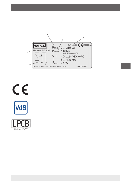
2. Seguridad
2.4 Rótulos / Marcajes de seguridad
Placa indicadora
Prange ... Rango de indicación
Modelo
Detalles del
conexionado
Explicación de símbolos
CE, Comunidad Europea
Los instrumentos con este marcaje cumplen las directivas
europeas aplicables.
Los instrumentos con este marcado están certicados
por el VdS.
Los instrumentos con este marcado están certicados
por el LPCB.
11581752.02 09/2013 GB/D/F/E
WIKA manual de instrucciones modelos PGS10, PGS11 y PGS21
switch ... Punto de
P
conmutación
Número de referencia de la
declaración de prestaciones
Número de
identicación del
organismo de
certicación de
producto con año del
primer marcado CE
E
55
Page 56

3. Datos técnicos
3. Datos técnicos
Modelos PGS10, PGS11 y PGS21
Presión admisible
- Carga estática 3/4 x valor nal de escala
- Carga dinámica 2/3 x valor nal de escala
- Carga puntual Valor nal de escala
Inuencia de temperatura En caso de desviación de la temperatura de referencia
Tipo de protección
- Caja envolvente según EN 60529 / IEC 529
E
Temperatura admisible
- Ambiente -20 ... +60 °C
- sustancia a medir Máx. +60 °C
Para más datos técnicos véase la hoja técnica de WIKA PV 20.01,
PV 21.01, PV 21.02, SP 21.01, SP 21.03 y la documentación de pedido.
56
WIKA manual de instrucciones modelos PGS10, PGS11 y PGS21
en el sistema de medición (+20°C): max. ±0,4 %/10 K
de la gama de indicación
Modelo PGS10 y PGS11: IP 41
(en PGS11.040 con VdS: IP 54)
Modelo PGS21: IP 65
111581752.02 09/2013 GB/D/F/E
Page 57

4. Construcción y funcionamiento / 5. Contactos ...
4. Construcción y funcionamiento
Descripción
Como elemento sensible se aplica el muelle tubular, muy habitual en la
instrumentación de presión, debido a su robustez y su fácil manejo. Al
someterles a presión estos elementos se deforman en la zona exible.
Ese movimiento se convierte en un movimiento giratorio a través de un
mecanismo de medida mecánico (ruedas dentadas). Además está instalado un contacto eléctrico de alarma, el contacto de acción magnética. El
contacto abre o cierra los circuitos eléctricos conectados si se sobrepasan
los valores límite ajustables.
Volumen de suministro
Comparar mediante el albarán si se han entregado todas las piezas.
5. Contactos eléctricos
Conexión eléctrica
■
La conexión eléctrica sólo la puede realizar personal especializado y
cualicado
■
Conexión de los contactos a través de cables o bornes en la caja de
cables (clavija de salida lateral)
■
Asignación de bornes indicada en la placa indicadora de tipo del
manómetro
■
Integrar los instrumentos en la conexión equipotencial de la instalación.
Compatibilidad electromagnética
EMC según EN 60947-5-2.
Proteger los instrumentos contra campos electromagnéticos fuertes.
11581752.02 09/2013 GB/D/F/E
WIKA manual de instrucciones modelos PGS10, PGS11 y PGS21
E
57
Page 58

5. Contactos eléctricos
Salida de cable
Contacto individual Contacto doble
rojo: U
negro: SP 1 naranja: SP 1
Conexión eléctrica mediante conector (DN 50, 63)
E
Cuando el tipo de protección IP del conector es menor que el del
instrumento de medición de presión, este tipo de protección determina
el tipo de protección general del instrumento.
58
+ rojo: UB+ (common)
B
negro: SP 2
Conector angular EN 175301-803-C
Contacto individual Contacto doble
1: U
+ 1: UB+ (common)
B
2: SP 1 2: SP 1
3: SP 2
Conector circular M12 x 1
Contacto individual Contacto doble
1: U
+ 1: UB+ (common)
B
4: SP 1 4: SP 1
2: SP 2
Conector circular M8 x 1
Contacto individual Contacto doble
1: U
+ 1: UB+ (common)
B
4: SP 1 4: SP 1
WIKA manual de instrucciones modelos PGS10, PGS11 y PGS21
3: SP 2
111581752.02 09/2013 GB/D/F/E
Page 59

5. Contactos eléctricos
Contacto de acción magnética
(contacto normalmente cerrado o contacto normalmente abierto)
Los instrumentos se entregan con un contacto individual o doble (contacto
normalmente cerrado o abierto).
En el contacto normalmente cerrado, la laminilla de contacto tiene contacto
con el contacto de alarma y el arrastrador montado en el indicador separa esta
laminilla del contacto cuando aumenta la presión. Se interrumpe el circuito
eléctrico.
En el contacto normalmente abierto, la laminilla de contacto sigue el indicador
hasta alcanzar el contacto de alarma. Cuando se supera el contacto de alarma,
la laminilla de contacto tiene contacto y el circuito eléctrico está cerrado.
La respectiva función de conmutación del contacto está indicado por el número
1, 2, 12, 11 ó 22.
Ci-
Denomina-
fra
ción
1 Contacto
normalmente
abierto
(NO)
2 Contacto
normalmente
cerrado
(NC)
Contacto normal-
12
mente abierto/
cerrado
(NO-NC)
Contacto normal-
11
mente abierto/
abierto
(NO-NO)
Contacto normal-
22
mente cerrado/
cerrado
(NC-NC)
11581752.02 09/2013 GB/D/F/E
WIKA manual de instrucciones modelos PGS10, PGS11 y PGS21
Símbolo Función de conmutación /
dirección de ajuste
El contacto se cierra cuando aumenta la
presión o cuando el indicador se mueve en
el sentido de las agujas del reloj (estándar)
El contacto se abre cuando se reduce la
presión o cuando el indicador se mueve
en el sentido contrario de las agujas del
reloj (estándar)
El contacto se abre cuando aumenta la
presión o cuando el indicador se mueve en
el sentido de las agujas del reloj (estándar)
El contacto se cierra cuando se reduce la
presión o cuando el indicador se mueve
en el sentido contrario de las agujas del
reloj (estándar)
Véase la función de conmutación o la
dirección de ajuste del contacto individual
Véase la función de conmutación o la
dirección de ajuste del contacto individual
Véase la función de conmutación o la
dirección de ajuste del contacto individual
Código
1
5
2
4
E
59
Page 60
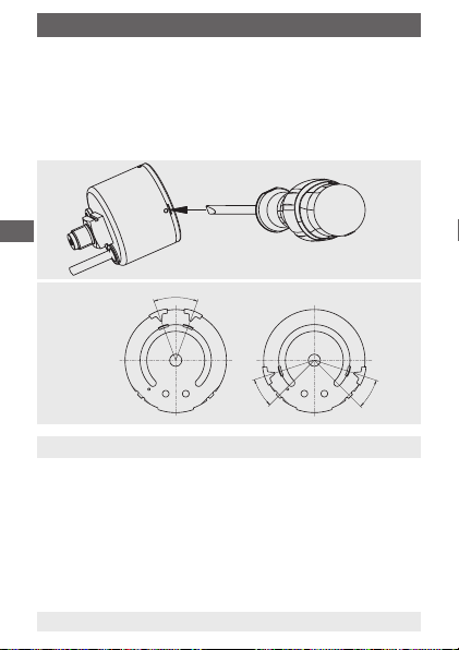
5. Contactos eléctricos / 6. Transporte, embalaje ...
Regulación del punto de contacto (modelos PGS10 y PGS11)
Soltar la mirilla utilizando un destornillador para ajustar el punto de
contacto. El contacto (aguja de marcaje roja) puede ajustarse manualmente
a la posición deseada. El contacto puede ajustarse entre un 10 % y 90 %
del valor nal de escala.
Montar la mirilla otra vez empujándola ligeramente en la caja.
E
En los instrumentos certicados por el VdS, dicha certicación
queda anulada si el cliente modica el punto de conmutación.
Ajustabilidad de
los contactos
6. Transporte, embalaje y almacenamiento
6.1 Transporte
Comprobar si el manómetro presenta eventuales daños causados en el
transporte. Noticar daños obvios de forma inmediata.
6.2 Embalaje
No quitar el embalaje hasta justo antes del montaje.
Guardar el embalaje porque es la protección ideal durante el transporte
(por ejemplo si el lugar de instalación cambia o si se envía el instrumento
para posibles reparaciones).
60
15 % v.f.e.
10 % v.f.e.
WIKA manual de instrucciones modelos PGS10, PGS11 y PGS21
31023461.01
10 % v.f.e.
111581752.02 09/2013 GB/D/F/E
Page 61
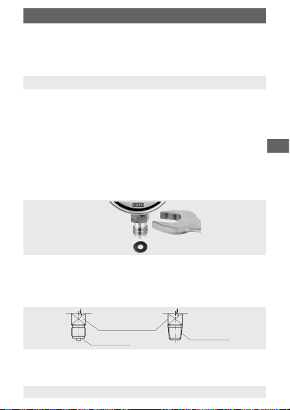
6. Transporte ... / 7. Puesta en servicio, funcionamiento
6.3 Almacenamiento
Condiciones admisibles en el lugar de almacenamiento
Temperatura de almacenamiento: -20 ... +70 °C
7. Puesta en servicio, funcionamiento
La conexión mecánica
Conforme a las reglas técnicas generales para manómetros (por ejemplo
EN 837-2 Recomendaciones relativas a la selección y montaje de
manómetros).
Si el manómetro está colocado en una posición más baja de la conexión
del proceso, la línea de medición debe lavarse bien antes de conectarla
para eliminar todos los para eliminar las partículas.
Para atornillar el instrumento, se debe utilizar la fuerza mediante el uso de
herramientas adecuadas sobre las supercies planas de ajuste -previstas y
no sobre la caja o la caja de conexiones.
Montaje mediante
llave de boca
E
Para el cierre de las conexiones de los manómetros con roscas cilíndricas
en la supercie de cierre
juntas perladas WIKA. Para roscas cónicas (por ejemplo, roscas NPT) se
realiza el cierre en la rosca
por ejemplo, cinta PTFE (EN 837-2).
El momento de arranque depende del tipo de cierre utilizado. Para poner
el manómetro en la posición que proporcionará la mejor lectura, se
recomienda una conexión con un manguito tensor o tuerca tapón.
11581752.02 09/2013 GB/D/F/E
WIKA manual de instrucciones modelos PGS10, PGS11 y PGS21
se debe instalar juntas planas, arandelas o
con material de cierre complementario, como
Supercie plana
de ajuste
Supercie de cierre
Junta en
la rosca
61
Page 62

7. Puesta en servicio, funcionamiento
Requerimientos en el lugar de instalación
Si el tubo que conecta al aparato de medición no fuera sucientemente
estable para asegurar una conexión exenta de vibraciones, se debería
efectuar la sujeción mediante un soporte de aparatos de medición (si es
necesario, mediante un tubo capilar exible). En el caso de no poder evitar
las vibraciones mediante las instalaciones apropiadas, debe instalarse
instrumentos con relleno de líquido. Se debe proteger los aparatos contra
contaminación y fuertes oscilaciones de la temperatura ambiente.
Instalación
■
Posición nominal según EN 837-1 / 9.6.7 ilustr 9: 90° ( ⊥ )
■
Conexión radial o en el lado posterior
E
■
¡No exponer los instrumentos a irradiación solar directa durante el
funcionamiento para evitar un calentamiento adicional!
Grupos de medición
Grupos de medición probados para los varios tipos de sustancias a medir.
Sustancias a medir líquidas Sustancias a medir gaseosas
Llenado de
la línea de
medición
Ejemplos
Manómetro
por encima
de la
conexión del
proceso
Manómetro
por debajo de
la conexión
del proceso
Las temperaturas ambiente y de funcionamiento permitidas
Se debe efectuar la instalación del manómetro de tal forma, que no se
excedan los límites de la temperatura ambiente ni la del material de medición,
incluyendo la inuencia de convección y la radiación térmica. Debe tenerse en
cuenta la inuencia de la temperatura en la precisión de indicación.
62
Líquido
Condensado
Parcialmente
desgasicante
Líquidos de
ebullición
Completamente
evaporado
"Gases
líquidos"
Gaseoso
Aire seco
Parcialmente
condesado
(húmedo)
Aire húmedo,
gases de
combustión
WIKA manual de instrucciones modelos PGS10, PGS11 y PGS21
Completamente condensado
Vapor de agua
111581752.02 09/2013 GB/D/F/E
Page 63

7. Puesta en servicio ... / 8. Mantenimiento y limpieza
Oscilación admisible en el lugar de instalación
■
Instalar los instrumentos sólo en lugares sin oscilaciones.
■
Si la línea al manómetro no es sucientemente estable para la jación
protegida contra sacudidas, hay que jar el manómetro mediante
elementos de jación adecuados para el montaje en la pared y/o el
tubo, si fuera necesario, a través de una línea capilar.
■
El desacoplamiento del lugar de instalación puede efectuarse por
ejemplo mediante un capilar desde el punto de medición al manómetro
y mediante sujeción del manómetro mediante soporte.
■
Si esto no es posible, no se debe sobrepasar en ningun caso los
siguientes valores límites:
Rango de frecuencias < 150 Hz
Aceleración < 0,5 g (5 m/s
2
)
Puesta en servicio
Evitar golpes de ariete en todo caso durante la puesta en servicio, abrir las
válvulas de cierre despacio.
8. Mantenimiento y limpieza
8.1 Mantenimiento
■
Los instrumentos no requieren mantenimiento.
■
Controlar el instrumento y la función de conmutación una o dos veces al
año. Para eso, separar el instrumento del proceso y controlarlo con un
dispositivo de control de presión.
■
Todas las reparaciones solamente las debe efectuar el fabricante o
personal especializado e instruido.
11581752.02 09/2013 GB/D/F/E
WIKA manual de instrucciones modelos PGS10, PGS11 y PGS21
E
63
Page 64

8. Mantenimiento y limpieza / 9. Desmontaje y eliminación
8.2 Limpieza
¡CUIDADO!
■
Antes de la limpieza hay que separar debidamente el
manómetro de cualquier fuente de presión, apagarlo y
desenchufarlo de la red.
■
Limpiar el instrumento con un trapo húmedo.
■
Asegurarse de que las conexiones eléctricas no se
humedecen.
■
E
Lavar o limpiar el instrumento desmontado antes
de devolverlo para proteger a los empleados y el
medio ambiente de los peligros causados por medios
residuales.
9. Desmontaje y eliminación
¡ADVERTENCIA!
Restos de medios en manómetros desmontados pueden
crear riesgos para personas, medio ambiente e instalación.
Tomar adecuadas medidas de precaución.
9.1 Desmontaje
¡Desmontar el manómetro sólo si no está sometido a presión!
9.2 Eliminación de residuos
Una eliminación incorrecta puede provocar peligros para el medio
ambiente.
Eliminar los componentes de los instrumentos y los materiales de
embalaje conforme a los reglamentos relativos al tratamiento de residuos
y eliminación vigentes en el país de utilización.
64
WIKA manual de instrucciones modelos PGS10, PGS11 y PGS21
111581752.02 09/2013 GB/D/F/E
Page 65

División: MP-IG
Control de calidad: MP-IG
Peter Koll
Daniel Kotlewski
Anexo 1: Declaratión de prestaciones modelo PGS11.040
Declaración de Prestaciones
Según Reglamento de Productos de Construcción EU Nr. 305/2011
1. Descripción: Manómetro con contacto eléctrico
2. Modelo: PGS11.040 conforme la hoja de datos SP 21.01
3. Aplicación según EN 12094-10: 2003
Componente para la aplicación en dispositivos contra incendios con agentes extintores gaseosos instalados
en edificios que forman parte de una instalación.
4. Fabricante:
WIKA Alexander Wiegand SE & Co.KG
Alexander-Wiegand-Str. 30, DE 63911 Klingen
5. Representante: No procede
6. Evaluación: Systema 1
7. Organismo de notificación:
VdS Schadenverhütung GmbH, 0786 ha realizado la comprobación del modelo, la inspección inicial de la
fábrica y de la gestión de control de la unidad de producción con monitorización continua, evaluación y
valorización de la gestón de control bajo sistema 1 y ha emitido el certificado de la CE 0786-CPD-30089.
8. Evaluación técnica europea: No procede
9. Prestaciones declaradas
Ca
racterísticas esenciales Prestación EN 12094-10:2003
Fiabilidad operativa - Generales aprobado 4.1.1
Condiciones nominales de activación/Tolerancia de activación
- Clase de exactitud y diámetro nominal aprobado 4.1.2
Estabilidad de la fiabilidad operativa contra - corrosión aprobado 4.1.3
Condiciones nominales de activación/Tolerancia de activación
- Clase de exactitud y diámetro nominal aprobado 4.2.1
Fiabliidad operativa
- Construcción
- Presión interior
- Seguridad operativa
- Temperatura
Estabilidad de la fiabilidad operativa contra - Corrosión aprobado 4.2.6
10. Las prestaciones del producto según apartados 1 y 2 corresponden a las prestaciones declaradas según
apartado 9. La responsabilidad para al emisión de esta declaracón de prestacioens la asume exclusivamente el
fabricante según apartado 4.
Firma para y en nombre de
WIKA Alexander Wiegand SE & Co. KG
Klingenberg, 2013-08-02
Firma, autorizada por la compañia
WIKA Alexander Wiegand SE & Co. KG
Alexander-Wiegand-Straße 30
63911 Klingenberg
Germany
11581752.02 09/2013 GB/D/F/E
WIKA manual de instrucciones modelos PGS10, PGS11 y PGS21
Documento No.: 14059917.02
Tel. +49 9372 132-0
Fax +49 9372 132-406
E-Mail info@wika.de
www.wika.de
berg
Kommanditgesellschaft: Sitz Klingenberg –
Amtsgericht Aschaffenburg HRA 1819
Komplementärin: WIKA Verwaltungs SE & Co. KG –
Sitz Klingenberg –Amtsgericht Aschaffenburg
HRA 4685
aprobado
aprobado
aprobado
aprobado
4.2.2
4.2.3
4.2.4
4.2.5
Komplementärin:
WIKA International SE -Sitz Klingenberg Amtsgericht Aschaffenburg HRB 10505
Vorstand: Alexander Wiegand
Vorsitzender des Aufsichtsrats: Dr. Max Egli
E
65
Page 66
Tel. +49 9372 132-0
www.wika.de
Firma, autorizadapor la compañia
Anexo 2: Declaratión de prestaciones modelo PGS21.050
Declaración de Prestaciones
Según Reglamento de Productos de Construcción EU Nr. 305/2011
1. Descripción: Manómetro con contacto eléctrico
2. Modelo: PGS21.050 onforme la hoja de datos SP 21.03
3. Aplicación según EN 12094-10: 2003
Componente para la aplicación en dispositivos contra incendios con agentes extintores gaseosos instalados
en edificios que forman parte de una instalación.
4. Fabricante:
WIKA Alexander Wiegand SE & Co.KG
Alexander-Wiegand-Str. 30, DE 63911 Klingenberg
5. Representante: No procede
6. Evaluación: Systema 1
E
7. Organismo de notificación:
VdS Schadenverhütung GmbH, 0786 ha realizado la comprobación del modelo, la inspección inicial de la
fábrica y de la gestión de control de la unidad de producción con monitorización continua, evaluación y
valorización de la gestón de control bajo sistema 1 y ha emitido el certificado de la CE 0786-CPD-30095.
8. Evaluación técnica europea: No procede
9. Prestaciones declaradas
Cara
cterísticas esenciales Prestación EN 12094-10:2003
Fiabilidad operativa - Generales aprobado 4.1.1
Condiciones nominales de activación/Tolerancia de activación
- Clase de exactitud y diámetro nominal aprobado 4.1.2
Estabilidad de la fiabilidad operativa contra - corrosión aprobado 4.1.3
Condiciones nominales de activación/Tolerancia de activación
- Clase de exactitud y diámetro nominal aprobado 4.2.1
Fiabliidad operativa
- Construcción
- Presión interior
- Seguridad operativa
- Temperatura
Estabilidad de la fiabilidad operativa contra - Corrosión aprobado 4.2.6
10. Las prestaciones del producto según apartados 1 y 2 corresponden a las prestaciones declaradas según
apartado 9. La responsabilidad para al emisión de esta declaracón de prestacioens la asume exclusivamente el
fabricante según apartado 4.
Firma para y en nombre de
WIKA Alexander Wiegand SE & Co. KG
Klingenberg, 2013-08-02
División: MP-IG Control de calidad: MP-IG
Peter Koll Daniel Kotlewski
WIKA Alexander Wiegand SE & Co. KG
Alexander-Wiegand-Straße 30
63911 Klingenberg
Germany
66
WIKA manual de instrucciones modelos PGS10, PGS11 y PGS21
Documento No.: 14059919.02
Fax +49 9372 132-406
E-Mail info@wika.de
Kommanditgesellschaft: Sitz Klingenberg –
Amtsgericht Aschaffenburg HRA 1819
Komplementärin: WIKA Verwaltungs SE & Co. KG –
Sitz Klingenberg –Amtsgericht Aschaffenburg
HRA 4685
aprobado
aprobado
aprobado
aprobado
4.2.2
4.2.3
4.2.4
4.2.5
Komplementärin:
WIKA International SE -Sitz Klingenberg Amtsgericht Aschaffenburg HRB 10505
Vorstand: Alexander Wiegand
Vorsitzender des Aufsichtsrats: Dr. Max Egli
111581752.02 09/2013 GB/D/F/E
Page 67

WIKA global
Europe
Austria
WIKA Messgerätevertrieb
Ursula Wiegand GmbH & Co. KG
Perfektastr. 83
1230 Vienna
Tel. +43 1 8691631
Fax: +43 1 8691634
info@wika.at
www.wika.at
Belarus
WIKA Belrus
Ul. Zaharova 50B, Oce 3H
220088 Minsk
Tel. +375 17 2945711
Fax: +375 17 2945711
info@wika.by
www.wika.by
Benelux
WIKA Benelux
Industrial estate De Berk
Newtonweg 12
6101 WX Echt
Tel. +31 475 535500
Fax: +31 475 535446
info@wika.nl
www.wika.nl
11581752.02 09/2013 GB/D/F/E
WIKA Betriebsanleitung Typen PGS10, PGS11 und PGS21
Bulgaria
WIKA Bulgaria EOOD
Akad.Ivan Geshov Blvd. 2E
Business Center Serdika
1330 Soa
Tel. +359 2 82138-10
Fax: +359 2 82138-13
info@wika.bg
www.wika.bg
Croatia
WIKA Croatia d.o.o.
Hrastovicka 19
10250 Zagreb-Lucko
Tel. +385 1 6531-034
Fax: +385 1 6531-357
info@wika.hr
www.wika.hr
Finland
WIKA Finland Oy
Melkonkatu 24
00210 Helsinki
Tel. +358 9 682492-0
Fax: +358 9 682492-70
info@wika.
www.wika.
France
WIKA Instruments s.a.r.l.
Parc d‘Aaires des Bellevues
8 rue Rosa Luxembourg
95610 Eragny-sur-Oise
Tel. +33 1 343084-84
Fax: +33 1 343084-94
info@wika.fr
www.wika.fr
67
Page 68

WIKA global
Germany
WIKA Alexander Wiegand SE &
Co. KG
Alexander-Wiegand-Str. 30
63911 Klingenberg
Tel. +49 9372 132-0
Fax: +49 9372 132-406
info@wika.de
www.wika.de
Italy
WIKA Italia S.r.l. & C. S.a.s.
Via G. Marconi 8
20020 Arese (Milano)
Tel. +39 02 93861-1
Fax: +39 02 93861-74
info@wika.it
www.wika.it
Further WIKA subsidiaries worldwide can be found online at www.wika.com.
Weitere WIKA-Niederlassungen weltweit nden Sie online unter www.wika.de.
La liste des autres liales WIKA dans le monde se trouve sur www.wika.fr.
Otras sucursales WIKA en todo el mundo puede encontrar en www.wika.es.
WIKA Alexander Wiegand SE & Co. KG
Alexander-Wiegand-Straße 30
63911 Klingenberg • Germany
Tel. +49 9372 132-0
Fax +49 9372 132-406
info@wika.de
www.wika.de
68
WIKA Betriebsanleitung Typen PGS10, PGS11 und PGS21
Poland
WIKA Polska S.A.
Ul. Legska 29/35
87-800 Wloclawek
Tel. +48 54 230110-0
Fax: +48 54 230110-1
info@wikapolska.pl
www.wikapolska.pl
Romania
WIKA Instruments Romania S.R.L.
050897 Bucuresti
Calea Rahovei Nr. 266-268
Corp 61, Etaj 1
Tel. +40 21 4048327
Fax: +40 21 4563137
m.anghel@wika.ro
www.wika.ro
11581752.02 09/2013 GB/D/F/E
 Loading...