

Page 1
Operating instructions
Betriebsanleitung
Mode d´emploi
Manual de instrucciones
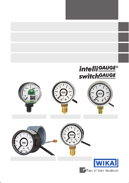
Pressure gauge with electrical output signal and
pressure gauge with electronic pressure switch
Druckmessgerät mit elektrischem Ausgangssignal und
Druckmessgerät mit elektronischem Druckschalter
Manomètre avec signal de sortie électrique et
manomètre avec pressostat électronique
Manómetro con señal eléctrica y
manómetro con presostato electrónico
PGT01 PGT21, PGS25PGT11, PGS07
PGT02, PGS05 PGT10, PGS06
GB
D
F
E
Page 2

Operating instructions
GB
intelliGAUGE / switchGAUGE
Betriebsanleitung
D
intelliGAUGE / switchGAUGE
Mode d´emploi
F
intelliGAUGE / switchGAUGE
Manual de instrucciones
E
intelliGAUGE / switchGAUGE
© 2010 WIKA Alexander Wiegand SE & Co. KG
All rights reserved. / Alle Rechte vorbehalten.
®
WIKA
is a registered trademark in various countries.
®
WIKA
ist eine geschützte Marke in verschiedenen Ländern.
Prior to starting any work, read the operating instructions!
Keep for later use!
Vor Beginn aller Arbeiten Betriebsanleitung lesen!
Zum späteren Gebrauch aufbewahren!
Lire le mode d‘emploi avant de commencer toute opération !
A conserver pour une utilisation ultérieure !
¡Leer el manual de instrucciones antes de comenzar cualquier trabajo!
¡Guardar el manual para una eventual consulta!
WIKA Operating instructions intelliGAUGE / switchGAUGE
2
Page 3-10
Seite 11-18
Page 19-26
Página 27-34
11349167.03 10/2011 GB/D/F/E
Page 3
Contents
Contents
1. Safety 4
2. Operating principle 4
3. Installation instruction 5
4. Installation and commissioning 6
5. Measuring arrangements 7
6. Electrical connection 8
7. Servicing / Maintenance / Cleaning / Repairing 9
8. Storage 9
9. Troubleshooting 10
10. Technical data 10
Information
This symbol provides you with information, notes and
tips.
Warning!
This symbol warns you against actions that can cause
11349167.03 10/2011 GB/D/F/E
injury to people or damage to the instrument.
WIKA operating instructions intelliGAUGE / switchGAUGE
GB
3
Page 4

1. Safety / 2. Operating principle
1. Safety
The appropriate national safety regulations (e.g. EN 837-2
GB
„Selection and installation recommendations for pressure
gauges“) must be ob-served when installing, commissioning and operating these devices.
■
Serious injuries and/or damage may occur should the appropriate
regulations not be observed.
■
Only appropriately qualied personnel should work on these
instruments.
■
The eective maximum surface temperature is not dependant upon
the device, but mainly on the temperature of the respective pressure medium! In the case of gaseous substances, the temperature
may increase due to compression warming. In these cases it may
be necessary to throttle the rate of change of pressure or reduce
the permissible temperature of the pressure medium.
2. Operating principle
Bourdon tubes are widely used as measuring elements for technical
pressure measurement due to their robustness and ease-of-use. Under
the inuence of pressure these measuring elements will deform within their
elastic range.
This movement is converted into a rotary motion by means of a mechanical
movement (gear). A magnet, xed to the pointer axle, turns with the
instrument´s pointer in direct proportion to the process pressure. The
electronics positioned facing the magnet detect the rotational motion of the
magnet.
The electronics’ non-contact sensor element (Hall sensor), aected by the
magnetic eld, detects any changes, free from any friction and wear to the
measuring element.
The sensor signal, which is in direct proportion to the angle of motion, is
transformed into an output signal. The span of the electrical output signal
corresponds to the measuring span of the dial.
An intelliGAUGE line pressure gauge with electrical output signal combines
all the advantages of an on-site display without the need for an external
power supply, with the demands of modern electronic measurement for
electrical signal transmission.
WIKA operating instructions intelliGAUGE / switchGAUGE
4
11349167.03 10/2011 GB/D/F/E
Page 5

3. Installation instructions
3. Installation instructions
Installation
■
Nominal position acc. EN 873-3 / 9.6.6 gure 7: 0° or 90°
■
Pressure connector bottom or rearside
Permissible vibration load at the mounting point
■
The instrument should always be installed in locations free of vibration.
■
If necessary, it is possible to isolate the instrument from the mounting
point by installing a exible connection line between the measuring
point and the pressure gauge and mounting the instrument on a suitable
bracket.
■
If this is not possible, the following limit values must not be exceeded:
Unlled devices: Frequency range 10 … 150 Hz
Accelaration < 0.5 g (5.0 m/s²)
Liquid lled devices: Frequency range 10 … 150 Hz
Accelaration < 4.0 g (39.2 m/s²)
The liquid lling has to be checked periodically.
The liquid level must not drop below 75 % of the instrument´s diameter.
Test connector
At certain use cases (e.g. steam vessels) isolating devices have to have a
test connector, so that the instrument can be checked without dismounting.
Mounting provisions
If the line for the pressure gauge is not rigid enough for vibration-free installation, fasten the instrument using appropriate fastening elements for wall
and / or pipe mounting, and, if necessary, by means of a capillary line.
Measuring system damping
If it is not possible to avoid vibration by means of appropriate mounting, use
pressure gauges with liquid lling.
Eects of temperature
The mounting of the pressure instrument has to be done in a way that the
operating temperature is neither exceeded nor falls below the permissible
operating temperature, even in consideration of thermal convection and
thermal radiation. Tailpipes of a suitable length or syphons may be used to
protect the pressure instrument and the isolating device.
The inuence of the temperature onto the accuracy of indication and of
measurement has to be noticed.
11349167.03 10/2011 GB/D/F/E
WIKA operating instructions intelliGAUGE / switchGAUGE
GB
5
Page 6

3. Installation instructions / 4. Installation and ...
Diaphragm seal / protective barrier
In case of aggressive, hot, highly viscous, contaminated or crystallizing
pressure media, which must not be allowed to intrude the measurign
element, diaphragm seals have to be used as separating barrier. A neutral
GB
transmission uid, used to transmit the pressure to the measuring element,
should be selected in consideration of the measuring range, the temperature and its compatibility with the pressure media.
The connection between the pressure gauge and the diaphragm seal must
not be released by no means.
Protection of the measuring element against overload
If the pressure media is subject to rapid pressure changes or pressure
impulses may be expected, these must not act directly upon the measuring
element. The eect of pressure impulses must be damped, e.g. by installing
an integrated restrictor screw (reduction of the cross section in the pressure
channel) or by connecting an adjustable throttle device in series.
Pressure test connection
The pressure test connection, with a suciently large bore size (≥ 6 mm
diameter), should be arranged, as far as possible, over a shut-o device,
in a position where the accuracy of the reading will not be aected by the
ow of the media being measured. The pipe between the pressure test
connection and the pressure instrument should have an inner diameter
large enough to avoid blockages or delays in pressure transmission. Also it
should not have any sharp bends. It is recommended that it is mounted with
a steep incline of approx. 1:15.
Piping
The piping should be arranged and tted so that it can withstand the
stresses caused by expansion, vibration and the inuence of heat. When
the media is gaseous, a water drain point should be provided at the lowest
point. For liquid pressure media, an air bleed should be provided at the
highest point.
4. Installation and commissioning
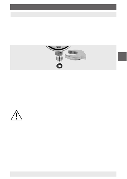
To acchieve a correct sealing of pressure connections suitable sealing
rings, sealing washers or WIKA prole seals have to be used. In order to get
the pressure instrument into an orientation that allows to read the on-site
indicator the best, a connector with an adjusting nut or an union nut is
recommended. When mounting and dismounting it is not allowed to tighten
the pressure instruments by using the housing, but on the spanner ats of
the stem, only.
WIKA operating instructions intelliGAUGE / switchGAUGE
6
11349167.03 10/2011 GB/D/F/E
Page 7
4. Installation and commissioning / 5. Measuring arrangements
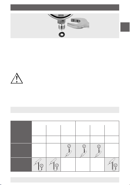
Installation using
a spanner
If the pressure transmitter is positioned lower than the pressure test
connection, the tailpipe has to be rinsed thoroughly prior to tting the gauge
to remove all foreign substances.
Once the pressure and electrical connections have been made, the trans-
mitter is ready for immediate use.
Before dismounting the pressure instrument the measuring element has to
be depressurized. Eventually the stress of the pipe has to be relieved.
Residual pressure medium remaining within the pressure
element may cause harm to men, facilities and environment.
Therefore sucient precautionary measures have to be
taken.
Pressure connector
In accordance with the general technical regulations for pressure gauges
(e.g. EN 837-2 „Selection and installation recommendations for pressure
gauges“).
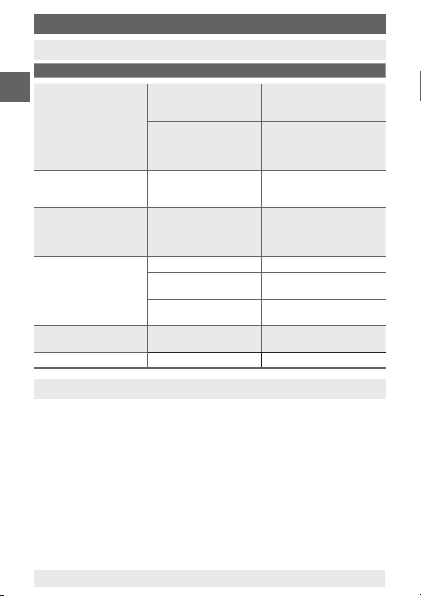
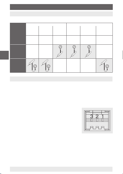
5. Measuring arrangements
Proven measuring arrangements for various types of media.
Liquid media Gaseous media
Contents of
tailpipe
Typically
Pressure
instrument
higher than
tapping point
Pressure instrument lower
than tapping
point
11349167.03 10/2011 GB/D/F/E
Liquid Liquid
Condensate
with
vapour
Boiling
liquid
Vapour
Gas only Wet gas Liquid
only
Liqueed
Dry air Moist air,
gas
Flue gas
gas condensate
Steam
WIKA operating instructions intelliGAUGE / switchGAUGE
GB
7
Page 8
6. Electrical connection
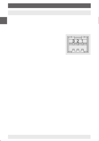
6. Electrical connection
The electrical connection of pressure gauges with an electrical output
/ electronic pressure switch is made via a plug or a cable. The correct
signal
GB
terminal connections can be seen in the table below.
Additionally the terminal assignment, output signal and necessary supply
voltage are written on the product label.
3-pin connector, model AMP Duoplug
Pin Signal
1 U
2 GND
3 U
Cable (2-wire)
Colour code Signal
black GND
red U
Cable (3-wire / 1 x NPN)
Colour code Signal
black GND
red U
orange U
Cable (4-wire / 2 x NPN)
Colour code Signal
black GND
red U
orange SP
brown SP
8
B+
SIG+
B+
B+
/ SP
SIG+
1
B+
1
2
WIKA operating instructions intelliGAUGE / switchGAUGE
11349167.03 10/2011 GB/D/F/E
Page 9
7. Servicing, Maintenance, Cleaning, Repairing / 8. Storage
7. Servicing, Maintenance, Cleaning, Repairing
Always open isolating devices gently, never abruptly, since this may
generate sudden pressure surges that may damage the gauge.
Pressure instruments with an electrical output signal
require no maintenance and oer a long service life, if handled and
switch
operated properly. If the zero point drifts, it means that the instrument has
been overloaded.
Clean the instrument with a moistened cloth. If badly soiled, moisten the
cloth thoroughly with soapy water.
Repairs should be only be carried out by the manufacturer or by appropri-
ately trained sta.
8. Storage
Before the system is stored, all traces of any medium
residue must be removed. This is particularly important,
if the media is a health hazard such as corrosive, toxic,
carcinogenic, radioactice, etc.
Before installation, in order to prevent damage to the pressure
instrument, the following points should be observed:
■
The pressure instrument should be left in its original packaging until
installation.
■
After taking the instrument out (e.g. for test), reuse the original
packaging material.
■
The storage temperature should not be less than -40 °C or more
than +90 °C
Avoid the following inuences:
■
Direct sunlight or vicinity to hot objects
■
Mechanical vibration
■
Sot, steam, dust, humidity and corrosive gasses
■
Potentially explosive environment, inammable atmospheres
11349167.03 10/2011 GB/D/F/E
WIKA operating instructions intelliGAUGE / switchGAUGE
/ electronic pressure
GB
9
Page 10
9. Trouble shooting / 10. Technical data
9. Trouble shooting
Malfunction Possible cause Measure
GB
No output signal /
no switch signal
Steady signal despite
pressure changes
Excessively high,
steady signal despite
pressure changes
Full span reading
too low
Zero signal too low /
too high
Switch signal instable Supply voltage too low Adjust supply voltage
10. Technical data
For technical data please refer to the technical data sheets.
PV 11.01 intelliGAUGE, model PGT01, plug connector, NS 40
PV 11.02 intelliGAUGE, model PGT02, cable outlet, NS 40
PV 11.05 intelliGAUGE, model PGT10, plastic case, IP 41, NS 40, 50
PV 11.06 intelliGAUGE, model PGT11, stainless steel case, IP 41, NS 40, 50
PV 11.03 intelliGAUGE, model PGT21, stainless steel case, NS 50
PV 21.03 switchGAUGE, model PGS05, cable outlet, NS 40
PV 21.05 switchGAUGE, model PGS06, plastic case, IP 41, NS 40, 50
PV 21.06 switchGAUGE, model PGS07, stainless steel case, IP 41, NS 40, 50
PV 21.04 switchGAUGE, model PGS25, stainless steel case, NS 50
WIKA operating instructions intelliGAUGE / switchGAUGE
10
Failure of power supply
or wiring interrupted
Electronic defect
through incorrect
supply voltage or
external voltage
Pressure entry blocked Check tailpipes and
Electronic defect
through incorrect
supply voltage or
external voltage
Supply voltage too low Adjust supply voltage
Load impedance
too high
Zero point shifted Return instrument to
Zero point shifted Return instrument to
Check power supply and
wiring; replace defective
components
Return instrument to
manufacturer for repair
pressure entry bore, if necessary clean it carefully
Return instrument to
manufacturer for repair
Consider max. permissible
load
manufacturer for repair
manufacturer for repair
11349167.03 10/2011 GB/D/F/E
Page 11
Inhalt
Inhalt
1. Sicherheit 12
2. Funktionsprinzip 12
3. Montagehinweise 13
4. Montage und Inbetriebnahme 15
5. Messanordnung 15
6. Elektrischer Anschluss 16
7. Bedienung / Wartung / Reinigung / Reparatur 17
8. Lagerung 17
9. Maßnahmen bei Störungen 18
10. Technische Daten 18
Information
Dieses Zeichen gibt Ihnen Informationen, Hinweise oder
Tipps.
Warnung!
Dieses Symbol warnt Sie vor Handlungen, die Schäden an
11349167.03 10/2011 GB/D/F/E
Personen oder am Gerät verursachen können.
WIKA Betriebsanleitung intelliGAUGE / switchGAUGE
D
11
Page 12

1. Sicherheit / 2. Funktionsprinzip
1. Sicherheit
Beachten Sie bitte unbedingt, bei Montage, Inbetriebnahme und Betrieb dieser Geräte die entsprechenden nationalen Sicherheitsvorschriften (z. B. EN 837-2 Auswahl- und
D
Einbauempfehlungen für Druckmessgeräte).
■
Bei Nichtbeachten der entsprechenden Vorschriften können
schwere Körperverletzungen und / oder Sachschäden auftreten.
■
Nur entsprechend qualiziertes Personal darf an diesen Geräten
arbeiten.
■
Die tatsächliche maximale Oberächentemperatur ist nicht von
diesen Geräten selbst abhängig, sondern hauptsächlich von
der jeweiligen Messstotemperatur! Bei gasförmigen Stoen
kann sich die Temperatur durch Kompressionswärme erhöhen.
In solchen Fällen muss ggf. die Geschwindigkeit der Änderung
des Drucks gedrosselt bzw. die zulässige Messstotemperatur
reduziert werden.
2. Funktionsprinzip
Als Messelement werden die in der technischen Druckmesstechnik wegen
ihrer Robustheit und einfachen Handhabung weit verbreiteten Rohrfeder-
messglieder verwendet. Unter dem Einuss des Drucks verformen sich diese
Messglieder im elastischen Bereich.
Diese Bewegung wird über ein mechanisches Messwerk (Zahnräder) in eine
Drehbewegung umgesetzt. Ein auf der Zeigerachse aufgesetzter Magnet
dreht sich proportional mit dem Instrumentenzeiger in direkter linearer
Abhängigkeit vom Prozessdruck. Die gegenüber dem Magneten positionierte
Elektronik erfasst die Drehbewegung des Magneten.
Ein magnetfeldabhängiger Sensor (Hall-Sensor) greift auf der elektronischen
Seite diese Veränderung berührungslos, verschleißfrei und ohne Rückwirkung
auf das Messglied ab.
Über einen Verstärker wird das der Drehbewegung proportionale Sensorsignal
in ein elektrisches Ausgangsignal umgewandelt. Die Spanne des elektrischen
Ausgangssignals entspricht der Messspanne auf dem Zierblatt. Mit entsprechender Transistorschaltung stehen auch Schaltausgänge zur Verfügung.
Ein Druckmessgerät mit elektrischem Ausgangssignal aus der Baureihe intelliGAUGE verbindet alle Vorteile einer fremdenergiefreien Vor-Ort-Anzeige mit
der Forderung nach einer elektrischen Signalübertragung für eine moderne
elektronische Messwerterfassung.
12
WIKA Betriebsanleitung intelliGAUGE / switchGAUGE
11349167.03 10/2011 GB/D/F/E
Page 13

3. Montagehinweise
3. Montagehinweise
Installation
■
Nennlage nach EN 873-3 / 9.6.6 Bild 7: 0° oder 90°
■
Druckanschluss hinten oder unten
Zulässige Schwingungsbelastung am Einbauort
■
Die Geräte sollten grundsätzlich nur an Stellen ohne Schwingungsbelastung eingebaut werden.
■
Gegebenenfalls kann z. B. durch eine exible Verbindungsleitung von der
Messstelle zum Druckmessgerät und die Befestigung über eine Messgerätehalterung eine Entkopplung vom Einbauort erreicht werden.
■
Falls dies nicht der Fall ist, dürfen folgende Grenzwerte nicht über-
schritten werden:
Ungefüllte Geräte: Frequenzbereich 10 … 150 Hz
Beschleunigung < 0,5 g (5,0 m/s²)
Flüssigkeitsgefüllte Geräte: Frequenzbereich 10 … 150 Hz
Beschleunigung < 4,0 g (39,2 m/s²)
Die Flüssigkeitsfüllung ist regelmäßig zu überprüfen.
Der Flüssigkeitsspiegel darf nicht unter 75 % des Gerätedurchmessers
fallen.
Prüfanschluss
In bestimmten Anwendungsfällen (z. B. Dampfkessel) müssen die Absperrarmaturen einen Prüfanschluss besitzen, damit das Druckmess-gerät ohne
Ausbau überprüft werden kann.
Messgerätebefestigung
Ist die Leitung zum Druckmessgerät für eine erschütterungsfreie
Anbringung nicht stabil genug, so ist die Befestigung über entsprechende
Befestigungselemente für Wand- und / oder Rohrmontage, ggf. über eine
Kapillarleitung vorzunehmen.
Messsystemdämpfung
Können Erschütterungen nicht durch geeignete Installation vermieden
werden, dann sollten Druckmessgeräte mit Flüssigkeitsfüllung eingesetzt
werden.
11349167.03 10/2011 GB/D/F/E
WIKA Betriebsanleitung intelliGAUGE / switchGAUGE
D
13
Page 14

3. Montagehinweise
Temperaturbelastung
Die Anbringung des Druckmessgerätes ist so auszuführen, dass die
zulässige Betriebstemperatur, auch unter Berücksichtigung des Einusses
von Konvektion und Wärmestrahlung, weder unter- noch überschritten wird.
Dazu sind Druckmessgerät und Absperrarmatur durch ausreichend lange
Messleitungen oder Wassersackrohre zu schützen.
D
Der Temperatureinuss auf die Anzeige- bzw. Messgenauigkeit ist zu
beachten.
Druckmittler / Schutzvorlagen
Bei aggressiven, heißen, hochviskosen, verunreinigten oder kristallisie-
renden Messstoen, die nicht in das Messglied eindringen dürfen, sind
Druckmittler als Trennvorlage vorzusehen. Zur Druckübertragung auf das
Messglied dient dann eine neutrale Mittlerüssigkeit, die entsprechend
dem Messbereich, der Temperatur und der Verträglichkeit mit dem
Messsto auszuwählen ist.
Die Verbindung zwischen Druckmessgerät und Druckmittler darf auf keinen
Fall gelöst werden.
Schutz der Messglieder vor Überlastung
Unterliegt der Messsto schnellen Druckänderungen oder ist mit Druckstößen zu rechnen, dürfen diese nicht direkt auf das Messglied einwirken. Die
Druckstöße müssen in ihrer Wirkung gedämpft werden, z. B. durch Einbau
einer Drosselstrecke (Verringerung des Querschnittes im Druckkanal) oder
durch Vorschaltung einer einstellbaren Drosselvorrichtung.
Druckentnahmestutzen
Der Druckentnahmestutzen soll mit einer genügend großen Bohrung
(≥≥ 6 mm) möglichst über ein Absperrorgan so angeordnet werden, dass
die Druckentnahme nicht durch eine Strömung des Messstoes verfälscht
wird. Die Messleitung zwischen Druckentnahmestutzen und Druckmessgerät soll zur Vermeidung von Verstopfung und Verzögerungen bei der
Druckübertragung einen genügend großen Innendurchmesser besitzen.
Sie soll auch ohne scharfe Krümmung sein. Ihre Verlegung mit einer steilen
Neigung von ca. 1:15 ist zu empfehlen.
Messleitung
Die Messleitung ist so auszuführen und zu montieren, dass sie die auftretenden Belastungen durch Dehnung, Schwingung und Wärmeeinwirkung
aufnehmen kann. Bei Gasen als Messsto ist an der tiefsten Stelle eine
Entwässerung, bei üssigen Messstoen an der höchsten Stelle eine
Entlüftung vorzusehen.
14
WIKA Betriebsanleitung intelliGAUGE / switchGAUGE
11349167.03 10/2011 GB/D/F/E
Page 15

4. Montage und Inbetriebnahme
4. Montage und Inbetriebnahme
Zur Abdichtung der Anschlüsse sind Flachdichtungen, Dichtlinsen oder
WIKA-Proldichtungen einzusetzen. Um das Druckmessgerät in die
Stellung zu bringen, in der sich die örtliche Anzeige am besten ablesen
lässt, ist ein Anschluss mit Spannmue oder Überwurfmutter zu empfehlen.
Beim Ein- und Ausschrauben dürfen die Druckmessgeräte nicht am
Gehäuse angezogen werden, sondern nur an den Schlüsselächen des
Anschlussstutzens!
Montage mit
Gabelschlüssel
Ist das Druckmessgerät tiefer als der Druckentnahmestutzen angeordnet,
muss die Messleitung vor dem Anschließen gut durchgespült werden, um
Fremdkörper zu beseitigen.
Nach Herstellen der Druckverbindung und der elektrischen Anschlüsse sind
die Druckmessgeräte sofort betriebsbereit.
Vor dem Ausbau der Druckmessgeräte ist das Messglied drucklos zu
machen. Ggf. muss die Messleitung entspannt werden.
Messstoreste in ausgebauten Druckmessgeräten können
zur Gefährdung von Menschen, Einrichtungen und Umwelt
führen. Ausreichende Vorsichtsmaßnahmen sind daher zu
ergreifen.
Druckanschluss
Entsprechend den allgemeinen technischen Regeln für Druckmessgeräte
(z. B. EN 837-2 „Auswahl- und Einbauempfehlungen für Druckmessgeräte“).
11349167.03 10/2011 GB/D/F/E
WIKA Betriebsanleitung intelliGAUGE / switchGAUGE
D
15
Page 16

5. Messanordnung / 6. Elektrischer Anschluss
5. Messanordnung
Bewährte Messanordnungen für verschiedene Messstoarten.
Füllung der
Messleitung
D
Beispiele
Druckmessgerät
oberhalb des
Entnahmestutzens
Druckmessgerät
unterhalb
des Entnahmestutzens
6. Elektrischer Anschluss
Der elektrische Anschluss des Druckmessgerätes mit elektrischem
Ausgangssignal / elektronischem Druckschalter wird über einen Stecker
oder ein Kabel hergestellt. Die genauen Anschlussbelegungen können
der nachfolgenden Aufstellung entnommen werden. Zusätzlich sind die
Anschlussbelegung, Ausgangssignal und erforderliche Hilfsenergie auf dem
Typenschild vermerkt.
Stecker 3-polig, Typ AMP Duoplug
Pin Belegung
1 U
2 GND
3 U
Kabelausgang (2-Leiter)
Litzenfarbe Belegung
schwarz GND
rot U
Kabelausgang (3-Leiter / 1 x NPN) Kabelausgang (4-Leiter / 2 x NPN)
Litzenfarbe Belegung Litzenfarbe Belegung
schwarz GND schwarz GND
rot U
orange U
16
Flüssige Messstoe Gasförmige Messstoe
üssig zum Teil
Kondensat siedende
B+
SIG+
B+
B+
SIG+
/ SP
ausgasend
Flüssigkeiten
vollständig
gasförmig z. T. kon-
verdampft
„Flüssig-
trockene
gase“
Luft
rot U
orange SP
braun SP
1
WIKA Betriebsanleitung intelliGAUGE / switchGAUGE
densiert
(feucht)
feuchte Luft,
Rauchgase
B+
1
2
vollständig
kondensiert
Wasserdampf
11349167.03 10/2011 GB/D/F/E
Page 17

7. Bedienung, Wartung, Reinigung und Reparatur / 8. ...
7. Bedienung, Wartung, Reinigung und Reparatur
Zur Vermeidung von Druckstößen dürfen Absperreinrichtungen nur zur
langsam geönet werden.
Die Druckmessgeräte mit elektrischem Ausgangssignal
Druckschalter
Behandlung und Bedienung durch eine hohe Lebensdauer aus. Sollte sich
der Nullpunkt verschoben haben, wurde das Gerät überlastet.
Reinigen Sie das Gerät mit einem angefeuchteten Tuch. Bei starker
Verschmutzung das Tuch mit Seifenlauge durchfeuchten.
Reparaturen sind ausschließlich vom Hersteller oder entsprechend
geschultem Personal durchzuführen.
sind wartungsfrei und zeichnen sich bei sachgemäßer
8. Lagerung
Vor der Einlagerung des Gerätes müssen alle ggf. anhaftenden Mediumsreste entfernt werden. Dies ist besonders
wichtig, wenn das Medium gesundheitsgefährdend ist, wie
z. B. ätzend, giftig, krebserregend, radioaktiv, usw.
Um Schäden zu vermeiden, sind für die Lagerung der Druckmessgeräte folgende Punkte zu beachten:
■
Druckmessgeräte in der Originalverpackung belassen.
■
Nach einer eventuellen Entnahme der Messgeräte für z. B. Prüfungen
sollte das Gerät wieder in der Originalverpackung eingelagert werden.
■
Lagertemperaturbereich -40 °C … +90 °C
Vermeiden Sie folgende Einüsse:
■
Direktes Sonnenlicht oder Nähe zu heißen Gegenständen
■
Mechanische Vibration, mechanischer Schock
■
Ruß, Dampf, Staub, Feuchtigkeit und korrosive Gase
■
Explosionsgefährdete Umgebung, entzündliche Atmosphären
11349167.03 10/2011 GB/D/F/E
WIKA Betriebsanleitung intelliGAUGE / switchGAUGE
/ elektronischem
D
17
Page 18

9. Maßnahmen bei Störungen / 10. Technische Daten
9. Maßnahmen bei Störungen
Störung Mögliche Ursache Maßnahme
Kein Ausgangssignal / kein
Schaltsignal
D
Gleich bleibendes
Ausgangssignal bei
Druckänderung
Zu hohes, bei
Druckänderung
gleich bleibendes
Ausgangssignal
Signalspanne zu
klein
Nullpunkt zu klein /
zu groß
Schaltsignal instabil
Keine Versorgungsspannung oder Leitungsbruch
Elektronik defekt durch
zu hohe Versorgungsspannung oder durch
Fremdspannung
Eingangskanal verstopft Eingangskanal bzw. Drossel-
Elektronik defekt durch
zu hohe Versorgungsspannung oder Fremdspannung
Versorgungsspannung
zu niedrig
Bürde zu hoch Max. zulässige Bürde
Nullpunkt verstellt Messgerät zur Instandset-
Nullpunkt verstellt Messgerät zur Instandset-
Versorgungsspannung
zu niedrig
10. Technische Daten
Technische Daten entnehmen Sie bitte den technischen Datenblättern.
PV 11.01 intelliGAUGE, Typ PGT01, Steckerausgang, NG 40
PV 11.02 intelliGAUGE, Typ PGT02, Kabelausgang, NG 40
PV 11.05 intelliGAUGE, Typ PGT10, Kunststogehäuse, IP 41, NG 40, 50
PV 11.06 intelliGAUGE, Typ PGT11, CrNi-Stahl-Gehäuse, IP 41, NG 40, 50
PV 11.03 intelliGAUGE, Typ PGT21, CrNi-Stahl-Gehäuse, NG 50
PV 21.03 switchGAUGE, Typ PGS05, Kabelausgang, NG 40
PV 21.05 switchGAUGE, Typ PGS06, Kunststogehäuse, IP 41, NG 40, 50
PV 21.06 switchGAUGE, Typ PGS07, CrNi-Stahl-Gehäuse, IP 41, NG 40, 50
PV 21.04 switchGAUGE, Typ PGS25, CrNi-Stahl-Gehäuse, NG 50
18
WIKA Betriebsanleitung intelliGAUGE / switchGAUGE
Spannungsversorgung und
Leitungen überprüfen; ggf.
defekte Teile austauschen
Messgerät zur Instandsetzung an Hersteller zurück
schraube reinigen
Messgerät zur Instandsetzung an Hersteller zurück
Versorgungsspannung
korrigieren
beachten
zung an Hersteller zurück
zung an Hersteller zurück
Versorgungsspannung
korrigieren
11349167.03 10/2011 GB/D/F/E
Page 19

Sommaire
Sommaire
1. Sécurité 20
2. Principe de fonctionnement 20
3. Instructions de montage 21
4. Installation et mise en service 22
5. Installation sur le point de mesure 23
6. Branchement électrique 24
Commande / Entretien / Nettoyage / Réparation
7.
8. Stockage 25
9. Mesures à prendre en cas de panne 26
10. Caractéristiques techniques 26
Informations
Ce signe vous donne des informations, des remarques ou
des conseils.
Avertissement !
Ce symbole vous avertit d'actions qui sont susceptibles
d'entraîner des dommages physiques ou matériels.
11349167.03 10/2011 GB/D/F/E
WIKA Mode d´emploi intelliGAUGE / switchGAUGE
F
25
19
Page 20

1. Sécurité / 2. Principe de fonctionnement
1. Sécurité
Respectez impérativement les directives de sécurité
nationales correspondantes lors du montage, de la mise
en service et de l'exploitation de ces appareils (p. ex. EN
837-2 Choix et recommandations relatives à l'installation
de manomètres).
■
Le non-respect des instructions correspondantes est susceptible
d‘entraîner des risques de blessure et/ou des dégâts matériels.
F
■
Seul le personnel habilité et qualié est autorisé à manipuler les
instruments.
■
La température maximale réelle de surface n‘est pas fonction
de l'appareil lui-même, mais principalement de la température
du uide de mesure utilisé ! Dans le cas de uides gazeux, la
température peut augmenter en raison de la chaleur consécutive
à la compression. Dans un tel cas, il conviendra de chercher à
diminuer la vitesse d'évolution de la pression ou la température
admissible du uide
2. Principe de fonctionnement
Les tubes de Bourdon sont très largement utilisés comme élément de
mesure dans la technologie de mesure de pression en raison de leur solidi-
té et de leur facilité d‘emploi. Sous l‘inuence de la pression, ces éléments
de mesure se déforment dans la zone d‘élasticité.
Ce mouvement est transformé en mouvement rotatif au moyen d‘un
dispositif de mesure mécanique (secteur denté). Un aimant xé sur
l‘axe de l‘aiguille tourne proportionnellement à la rotation de l‘aiguille de
l‘instrument en fonction de la pression process. L‘électronique positionnée
en face de l‘aimant saisit le mouvement de rotation de l‘aimant.
Un capteur indépendant du champ magnétique (capteur à eet Hall) mesure du côté électronique cette modication sans le moindre contact, sans
usure et sans réaction sur l'organe de mesure.
Au moyen d‘un amplicateur, le signal du capteur proportionnel au
mouvement de rotation est transformé en signal de sortie électrique.
L’échelledu signal de sortie électrique correspond à l’échelle de mesure du
le cadran. Des sorties de commutation sont également disponibles avec un
montage à transistor correspondant.
Un manomètre avec signal de sortie électrique de la série intelliGAUGE allie
tous les avantages d‘un achage local ne nécessitant aucune alimentation
externe et la demande d‘une transmission de signal électrique permettant
une surveillance électronique moderne des valeurs de mesure.
20
WIKA Mode d´emploi intelliGAUGE / switchGAUGE
11349167.03 10/2011 GB/D/F/E
Page 21

3. Instructions de montage
3. Instructions de montage
Installation
■
Position nominale selon EN 837-3 / 9.6.6 gure 7 : 0 °C ou 90°
■
Raccord vertical ou arrière
Contrainte de vibration admissible au point de mesure
■
Par principe, les appareils doivent être installés à des emplacements qui
ne sont pas soumis à des vibrations.
■
Le cas échéant, il est possible d'isoler l'appareil du point de mesure en
utilisant par exemple un exible entre le point de mesure et le manomètre
et en installant celui-ci à l‘aide d‘un support adapté.
■
Dans le cas où cela n'est pas possible, les seuils suivants ne doivent pas
être dépassés :
Appareils non remplis : plage de fréquence 10 … 150 Hz
Accélération < 0,5 g (5,0 m/s
Appareils remplis : plage de fréquence 10 … 150 Hz
Accélération < 4,0 g (39,2 m/s
Le niveau de liquide doit être contrôlé régulièrement.
Le niveau de remplissage du liquide ne doit pas descendre au-dessous de
75 % du diamètre du boîtier.
Prise de contrôle
Les spécications locales de sécurité telles par exemple celles liées aux
chaudières vapeur peuvent rendre nécessaire des dispositifs d’isolement
permettant le test sur site de l'appareil.
Fixation des appareils
Si le raccordement au manomètre n'est pas assez robuste pour réaliser
une xation exempte de vibrations, la xation doit être réalisée au moyen
d'éléments de xation pour montage mural et/ou sur tube, le cas échéant
par l'intermédiaire d'un capillaire.
Amortissement du système de mesure
Si des vibrations ne peuvent pas être évitées au moyen d'installations
appropriées, il est recommandé d‘utiliser des manomètres remplis de liquide.
Contraintes thermiques
La position de montage de l’appareil est à choisir en fonction de la
température de service qui ne doit pas être dépassée, en tenant compte
également de l‘inuence de la conduction et du rayonnement thermique.
11349167.03 10/2011 GB/D/F/E
WIKA Mode d´emploi intelliGAUGE / switchGAUGE
F
²
)
²
)
21
Page 22

3. Instructions de montage
Pour ce faire on utilisera des tuyaux-raccord susamments longs ou un
syphon placé avant le robinet d’isolement et l’appareil (prendre en considé-
ration l‘inuence de la température sur la précision de la mesure).
Séparateur / barrière de séparation
En cas de uide agressif, chaud, fortement visqueux, souillé ou cristallisant
qui ne doive pas pénétrer dans l'organe de mesure, on utilisera un sépara-
teur qui fera oce de barrière de protection pour l'instrument. Un liquide
de transmission qui servira à transmettre la pression à l'organe de mesure
F
devra être sélectionné en fonction de la plage de mesure, de la température
et de la compatibilité avec le uide de mesure.
L'assemblage du manomètre sur le séparateur ne devra en aucun cas être
démonté.
Protection de l'élément de mesure contre les surpressions
Si le uide de mesure est soumis à de brusques montées en pression
ou s'il faut s‘attendre à des coups de bélier, ceux-ci ne doivent pas agir
directement sur l‘organe de mesure. Les eets des coups de bélier doivent
être amortis, p. ex. par la pose d‘une vis frein (réduction de la section dans
le canal de pression) ou par l‘installation en amont d‘un
dispositif réglable d‘amortissement de la pression.
Raccord de la prise de pression
Le raccord de la prise de pression doit être pourvu d'un orice susamment
grand (≥ 6 mm), si possible posséder un robinet d'isolement et être installé
de façon à ce que le débit du uide ne perturbe pas la mesure. La tuyauterie
entre le raccord de mesure et le transmetteur de pression doit avoir un
diamètre susant an d'en éviter son bouchage ou de provoquer des
retards dans la transmission de la pression. On évitera également des
courbures trop importantes. Il est recommandé d'installer la tuyauterie avec
un rapport d'inclinaison de 1:15.
Tuyauterie
La tuyauterie est à concevoir et à installer de telle façon qu'elle supporte les
contraintes dues á des dilatations, vibrations et inuences thermiques. Pour
la mesure de gaz, il faut prévoir une purge de condensat au point le plus
bas de l'installation, et pour la mesure de liquides il faut une purge d'air au
point le plus èlevé.
22
WIKA Mode d´emploi intelliGAUGE / switchGAUGE
11349167.03 10/2011 GB/D/F/E
Page 23

4. Installation et mise en service
4. Installation et mise en service
Pour l'étanchéité des raccords, il faut utiliser des joints plats, des lentilles
d'étanchéité ou des joints prolés WIKA. Pour installer le manomètre dans
la position permettant la lecture la plus aisée de l'indication locale, il est
recommandé de réaliser le raccordement au moyen d'un écrou tournant ou
d'un écrou-chapeau. Lors du montage ou du démontage, les manomètres
ne doivent pas être serrés au niveau du boîtier, mais uniquement sur le
surplat au-dessus du letage du manomètre !
Montage avec
clé à fourche
En cas d'installation du transmetteur de pression au-dessous du point de
mesure, il faut nettoyer soigneusement la tuyauterie an d'éviter que des
particules ne pénètrent à l‘intérieur de l‘appareil.
Après raccordement du raccord process et branchement électrique de
l’appareil, celui-ci est prêt à fonctionner.
Le transmetteur de pression doit être démonté uniquement lorsqu'il est hors
pression. Si nécessaire vider la tuyauterie.
Les résidus de uide se trouvant à l'intérieur des
transmetteurs de pression démontés peuvent présenter
des dangers pour les personnes, l'environnement et
les installations. Il faut prendre toutes les précautions
nécessaires pour en assurer la sécurité.
Raccord process
Conformément aux règles techniques générales pour les manomètres
(par ex. EN 837-2 « Recommandations relatives au choix et à l'installation
des manomètres »).
11349167.03 10/2011 GB/D/F/E
WIKA Mode d´emploi intelliGAUGE / switchGAUGE
F
23
Page 24

5. Installation sur le point de mesure / 6. Branchement ...
5. Installation sur le point de mesure
Types d’installations éprouvés selon diérents uides.
Remplissage
de la conduite
de mesure
Exemples
F
Manomètre
au-dessus
du point de
mesure
Manomètre
au-dessous
du point de
mesure
6. Branchement électrique
Le branchement électrique du manomètre avec signal de sortie électrique
/ pressostat eléctronique est eectué à l‘aide d‘un connecteur ou d‘un
câble. La disposition exacte des connexions est illustrée sur les dessins
présentés ci-après. En outre, la disposition des connexions, le signal
de sortie et l‘alimentation nécessaires sont notés sur la plaque
signalétique de l‘appareil.
Connecteur 3 plots, type AMP Duoplug
Plot Signal
1 U
2 GND
3 U
Câble (2 ls)
Code couleur Signal
noir GND
rouge U
Câble (3 ls / 1 x NPN)
Code couleur Signal Code couleur Signal
noir
GND noir GND
rouge U
orange U
24
Fluides liquides Fluides gazeux
liquides en partie
condensat liquides en
B+
SIG+
B+
gazeux
ébullition
complètement
évaporés
« gaz
liquides »
uide
gazeux
air sec air humide,
Câble (4 ls / 2 x NPN)
1
rouge U
orange SP
marron SP
B+
SIG+
/ SP
WIKA Mode d´emploi intelliGAUGE / switchGAUGE
en partie
condensés
(humides)
gaz de combustion
B+
entièrement
condensé
vapeur
d‘eau
1
2
11349167.03 10/2011 GB/D/F/E
Page 25

7. Commande, Entretien, Nettoyage, Réparation / 8. ...
7. Commande, Entretien, Nettoyage, Réparation
Tout robinet d'isolement doit être ouvert progressivement et en aucun cas
brusquement an d'éviter les coups de bélier.
Les manomètres avec signal de sortie électrique
ne requièrent aucun entretien et se caractérisent par une longue durée de
vie s'ils sont traités et utilisés de manière appropriée. Un décalage du point
zéro signale une surpression subie par l‘appareil.
L'appareil se nettoie à l'aide d‘un chion humidié. S'il est fortement souillé,
humidier le chion avec de l'eau (et du savon de Marseille).
Les réparations ne doivent être eectuées que par le fabricant ou par du
personnel formé.
8. Stockage
Avant le stockage de l’appareil, tous les résidus du uide
doivent être éliminés. Ceci est particulièrement
important lorsque le produit est dangereux pour la santé,
ex. corrosif, toxique, cancérigène, radioactif, etc.
Avant l'installation, les points suivants doivent être respectés an de
d'éviter tout dommage sur l'appareil :
■
Laisser les transmetteurs de pression dans leur emballage d'origine
jusqu’à l'installation.
■
Après avoir démonté un transmetteur de pression (par exemple pour un
contrôle) le réemballer dans son emballage d'origine.
■
Température de stockage -40 °C … +90 °C
Évitez les conditions suivantes :
■
Lumière directe du soleil ou proximité avec des objets chauds
■
Vibrations mécaniques, chocs mécaniques (montage dicile)
■
Suie, vapeur, poussière, humidité et gaz corrosifs
■
Environnement explosif, atmosphères inammables
11349167.03 10/2011 GB/D/F/E
WIKA Mode d´emploi intelliGAUGE / switchGAUGE
/ pressostat eléctronique
F
25
Page 26

9. Mesures à prendre en cas de panne / 10. Données ...
9. Mesures à prendre en cas de panne
Panne Cause possible Mesure à prendre
Aucun signal de
sortie/ pas de signal
de commutation
F
Signal de sortie
constant malgré des
variations de pression
Signal de sortie trop
élevé et constant
malgré des variations
de pression
Plage de signalisation
trop faible
Point zéro trop faible/
trop élevé
Signal de
commutation instable
10. Caractéristiques techniques
Vous trouverez des données techniques dans les ches techniques.
PV 11.01 intelliGAUGE, Type PGT01,
PV 11.02 intelliGAUGE, Type PGT02,
PV 11.05 intelliGAUGE, Type PGT10, boîtier plastique, IP 41, Diam. 40, 50
PV 11.06 intelliGAUGE, Type PGT11, boîtier en
PV 11.03 intelliGAUGE, Type PGT21, boîtier en
PV 21.03 switchGAUGE, Type PGS15,
PV 21.05 switchGAUGE, Type PGS06, boîtier plastique, IP 41, Diam. 40, 50
PV 21.06 switchGAUGE, Type PGS07, boîtier en
PV 21.04 switchGAUGE, Type PGS25, boîtier en
26
Aucune tension d'alimentation
Rupture de cable
Electronique défectueuse,
conséquence d'une tension
d'alimentation trop élevée ou d'une
tension d'origine étrangère
Canal d'entrée bouché Nettoyer le canal d'entrée et/
Electronique défectueuse,
conséquence d'une tension
d'alimentation trop élevée ou d'une
tension d'origine étrangère
Tension d'alimentation trop faible Corriger la tension
Charge ohmique trop élevée Respecter la charge ohmique
Zéro déréglé Renvoi du manomètre au
Zéro déréglé Renvoi du manomètre au
Tension d'alimentation trop faible Corriger la tension
sortie connecteur
sortie câble
sortie câble
Contrôler l'alimentat. et le
câblage ; le cas échéant
changer les pièces défectueuses
Envoyer le transmetteur au
fabricant pour réparation
ou la vis d'étranglement
Envoyer le transmetteur au
fabricant pour réparation
d'alimentation
max. admise
fabricant pour réparations
fabricant pour réparations
d'alimentation
, Diam. 40
, Diam. 40
acier inox
, IP 41, Diam. 40, 50
acier inox
, Diam. 50
, Diam. 40
acier inox
, IP 41, Diam. 40, 50
acier inox
, Diam. 50
WIKA Mode d´emploi intelliGAUGE / switchGAUGE
11349167.03 10/2011 GB/D/F/E
Page 27

Contenido
Contenido
Seguridad
1.
Principio de funcionamiento
2.
Indicaciones de montaje
3.
Montaje y funcionamiento
4.
Disposición de medida
5.
Conexión eléctrica
6.
Servicio / Mantenimiento / Limpieza / Reparacion
7.
Almacenamiento
8.
Medidas en caso de fallos
9.
Datos técnicos
10.
Información
Este signo indica informaciones, notas o consejos.
¡Advertencia!
Este símbolo indica advertencias relativas a acciones que
puedan dañar personas o a la instalación.
11349167.03 10/2011 GB/D/F/E
WIKA Manual de instrucciones intelliGAUGE / switchGAUGE
28
28
29
30
E
31
32
33
33
34
34
27
Page 28

1. Seguridad / 2. Principio de funcionamiento
1. Seguridad
Es imprescindible observar las prescripciones nacionales
de seguridad (p. ej. EN 837-2 "Recomendaciones relativas
a la selección y montaje de manómetros") durante el montaje, la puesta en servicio y la utilización de estos aparatos.
■
Riesgo de lesiones graves y/o daños materiales en caso de no
observar las instrucciones correspondientes.
■
La manipulación de los instrumentos solamente la deben ejecutar
personal cualicado.
■
¡La temperatura máx. real de las supercies no depende de los
E
aparatos sino principalmente de la temperatura del medio! En el
caso de uidos gaseosos, la temperatura puede aumentar por
razón del calor consecuencia de la compresión. En estos casos,
hay que disminuir la hay que disminuir el ratio de presión o
reducir la temperatura admisible del medio, si fuera necesario.
2. Principio de funcionamiento
Los muelles de Bourdon son ampliamente empleados como elementos de
medida técnica debido a su robustez y su fácil utilización. Bajo la inuencia
de la presión estos elementos de medida se deforman dentro de su rango
elástico.
Este movimiento se convierte en un movimiento giratorio mediante un
mecanismo mecánico. El imán colocado en el eje de la aguja gira con
la aguja del instrumento, proporcionalmente a la presión de proceso. La
electrónica posicionada frente al imán detecta el movimiento giratorio del
imán.
Un sensor dependiente del campo magnético (sensor hall)
mide en el lado electrónico ese cambio sin fricción, sin desgaste y sin
reacción en el elemento de medición.
Un amplicador convierte la señal proporcional al movimiento giratorio
en una señal eléctrica de salida. El alcance de la señal eléctrica de
salida corresponde al alcance de medición en la esfera. Con circuito
de transistores correspondiente están disponibles también salidas de
conmutación.
La línea de manómetros intelliGAUGE con señal de salida eléctrica,
combina todas las ventajas de una visualización in –situ sin la necesidad de
28
WIKA Manual de instrucciones intelliGAUGE / switchGAUGE
11349167.03 10/2011 GB/D/F/E
Page 29

3. Indicaciones de montaje
una fuente externa de alimentación con la demanda de la moderna medida
electrónica para señal de transmisión eléctrica.
3. Indicaciones de montaje
Instalación
■
Posición nominal según EN 837-3 / 9.6.6 ilustr. 7: 0° ó 90°
■
Conexión a presión en el lado posterior o en bajo
Carga de vibración admisible en el punto de montaje
■
Instalar los instrumentos sólo en lugares exentos de vibraciones.
■
Si es necesario, es posible aislar el instrumento del punto de montaje
mediante la instalación de una conexión exible entre el punto de medida
y el manómetro, mediante la jación del manómetro con un soporte de
jación.
■
Si esto no es posible, no sobrepasar los valores límite siguientes en
ningún caso:
Instrumentos vacíos: gama de frecuencias 10 … 150 Hz
aceleración < 0,5 g (5,0 m/s
Instrumentos llenados de líquido: gama de frecuencia 10 … 150 Hz
aceleración < 4,0 g (39,2 m/s
Comprobar el llenado de líquido a intervalos regulares.
El nivel de líquido no debe caer debajo del 75 % del diámetro del instrumento.
Toma de control
En ciertas aplicaciones (como por ejemplo, calderas de vapor) los órganos
de cierre deben de estar provistos de una toma de control con la nalidad
de poder controlar el transmisor de presión sin desmontarlo.
Fijación de los aparatos de medida
Si la línea al manómetro no es sucientemente estable para la jación
protegida contra vibraciones, hay que jar el manómetro mediante elementos de jación adecuados para el montaje en la pared y/o el tubo, si fuera
necesario, a través de un tubo capilar.
Amortiguación del sistema de medida
Si no es posible evitar vibraciones mediante una instalación adecuada, hay
que utilizar manómetros llenados con líquido.
11349167.03 10/2011 GB/D/F/E
WIKA Manual de instrucciones intelliGAUGE / switchGAUGE
E
²
)
²
)
29
Page 30

3. Indicaciones de montaje
Efectos de la temperatura
La temperatura operativa del transmisor de presión, que resulta de
los efectos del medio de presión, las temperaturas ambientes y, posiblemente, la radiación de calor, no deben superar el rango de temperatura
para el cual está diseñado el transmisor de presión. Puede utilizarse una
torre de refrigeración con la forma adecuada o sifones rellenos de agua
para separar el transmisor de presión. Tener en consideración la inuencia
de la temperatura respecto a la presión de la medida.
Sellos separadores / láminas de protección
Utilizar sellos separadores como membranas de protección en caso de
medios agresivos, calientes, de alta viscosidad o cristalizantes que no
deben penetrar en el elemento de medición. Para transmitir la presión al
E
elemento de medición se utiliza un líquido a seleccionar con respecto
al rango de medición, la temperatura y la compatibilidad con el medio.
En ningún caso aojar la conexión entre el manómetro y el sello
separador.
Protección de los elementos de medición contra una sobrecarga
Si el medio está sujeto a cambios rápidos de presión o si han de
esperarse golpes de ariete, no deben actuar directamente en el elemento
de medición. Hay que amortiguar los golpes de ariete, p. ej. instalando un
obturador de presión (reducción del corte transversal en el conducto
a presión) o preconectando un dispositivo de obturación ajustable.
Conexión del proceso
En la medida de lo posible, se deberá contar con una conexión del proceso
de un diámetro interior sucientemente grande (≥≥ 6 mm de diámetro)
sobre un dispositivo de cierre y en una posición en la que la exactitud de
la lectura no se vea afectada por el ujo de los medios que se miden. La
tubería entre la conexión del proceso y el transmisor de presión deberá
poseer un diámetro interno sucientemente grande para evitar bloqueos
o demoras en la transmisión de presión. Tampoco se deberá poseer
curvas pronunciadas. Se recomienda instalarlo con un declive continuo de
aproximadamente 1:15.
Tubería
La tubería debe montarse e instalarse de modo que pueda tolerar las
tensiones causadas por la expansión, la vibración y la inuencia del calor.
Cuando el medio es gaseoso, deberá proveerse un punto de drenaje de
agua en el punto más bajo. Debe proveerse una purga de aire en el punto
más alto en caso de medios de presión líquidos.
30
WIKA Manual de instrucciones intelliGAUGE / switchGAUGE
11349167.03 10/2011 GB/D/F/E
Page 31
4. Montaje y funcionamiento
4. Montaje y funcionamiento
La correcta conexión de presión debe realizarse mediante una junta de
cierre o una arandela la de cierre o bien las juntas de perl WIKA adecuadas. Recomendamos conectar el manómetro mediante un manguito de
sujeción o un racor de unión para colocar el manómetro en la posición en
que pueda leerse lo mejor la indicación local. ¡Al montar y desmontar no
deben sujetarse los manómetros por la caja sino sólo en las supercies
provistas para la llave en el racor de conexión!
Montaje mediante
llave ja
En caso de que el transmisor de presión se posicione por debajo de punto
de conexión, el codo de trubería debe limpiarse integramente antes de
montar el transmisor
Una vez se ha efectuado las conexiones de presión y eléctrica, los transmisores están listos para su uso.
No debe intentarse retirar un transmisor presurizado. El sistema de presión
debe estar completamente ventilado, ya que el transmisor no podrá
aislarse.
El remanente del medio de presión contenido en el elemen-
to de presión puede ser peligroso o tóxico. Esto debe
considerarse cuando se manipula y almacena el transmisor
retirado.
Conexión a presión
Conforme a las reglas técnicas generales para manómetros (por ejemplo
EN 837-2 "Recomendaciones relativas a la selección y montaje de
manómetros").
11349167.03 10/2011 GB/D/F/E
WIKA Manual de instrucciones intelliGAUGE / switchGAUGE
E
31
Page 32
5. Disposición de medida / 6. Conexión eléctrica
5. Disposición de medida
Preparativos comprobados de medición para diversos tipos de medios.
Contenido
del tubo de
aspiración
Generalmente
Instrumento
por encima
del punto de
medica
E
Instrumento
por debajo
del punto de
medida
6. Conexión eléctrica
El manómetro con señal eléctrica de salida
conectado a la electricidad mediante una clavija o un cable. Los esquemas
exactos de la instalación eléctrica pueden observarse en los dibujos
siguientes. La señal de salida y la fuente de alimentación necesaria se
proporcionan en la placa de potencia de régimen, además de los detalles de
la instalación eléctrica.
Conector de 3 polos, modelo AMP Duoplug
Pin Ocupación
1 U
2 GND
3 U
Salida del cable (2 hilos)
Color del cordón Ocupación
negro GND
rojo U
Salida del cable (3 hilos / 1 x NPN) Salida del cable (4 hilos / 2 x NPN)
Color del cordón Ocupación Color del cordón Ocupación
negro GND negro GND
rojo U
naranja U
marrón
32
Medios líquidos Medios gaseosos
Líquido Líquido
Condensado
Vapor úni-
con vapor
camente
Líquido en
GLP Aire seco Aire húmedo
ebullición
Gas únicamente
Gas
húmedo
Gas de
combustión
/ presostato electrónico
B+
SIG+
B+
1
rojo U
naranja SP
SP
B+
SIG+
/ SP
WIKA Manual de instrucciones intelliGAUGE / switchGAUGE
Condensado
de gas
líquido
Vapor de agua
está
B+
1
2
11349167.03 10/2011 GB/D/F/E
Page 33

7. Servicio, Mantenimiento, Limpieza, Reparacion / 8. ...
7. Servicio, Mantenimiento, Limpieza, Reparacion
Para evitar golpes de ariete, hay que abrir lentamente los dispositivos de
cierre.
Los manómetros con señal eléctrica de salida
requieren mantenimiento y se distinguen por una vida útil elevada si se
utilizan y operan adecuadamente. Si se ha desplazado el punto cero, el
aparato ha sido sobrecargado.
Limpiar los instrumentos con un trapo húmedo. En caso de gran suciedad
mojar el trapo con lejía de jabón.
Todas las reparaciones solamente las debe efectuar el fabricante o personal especializado.
8. Almacenamiento
Antes del almacenamiento del aparato deben quitarse
todos los restos de medios eventualmente adheridos. Esto
es especialmente importante cuando el medio es nocivo
para la salud, como p. ej. cáustico, tóxico, cancerígeno,
radioactivo, etc.
Previo a la instalación, a n de evitar daños en los transmisores, siga
los puntos a continuación:
■
El transmisor de presión debe permanecer en su embalaje original hasta
la instalación.
■
Después de sacar el transmisor (por ejemplo, para pruebas) reutilice el
material de embalaje original.
■
La temperatura de almacenamiento no debe superar -40 °C … +90 °C
Evite las siguientes inuencias:
■
Luz solar directa o proximidad a objetos calientes
■
Vibración mecánica, impacto mecánico (apoyarlo de golpe)
■
Hollín, vapor, polvo, humedad y gases corrosivos
■
Entorno potencialmente explosivo, atmósferas inamables
11349167.03 10/2011 GB/D/F/E
WIKA Manual de instrucciones intelliGAUGE / switchGAUGE
/ presostato electrónico no
E
33
Page 34

9. Medidas en caso de fallos / 10. Datos técnicos
9. Medidas en caso de fallos
Falla Causa posible Solución
Sin señal de salida /
no señal de
conmutación
Señal estable a pesar de
la variación de presión
E
Señal estable y demasiado alta a pesar de la
variación de presión
Lectura del intervalo
total de medida
demasiado bajo
Señal de cero demasiado
baja / demasiado alta
Señal de conmutación
inestable
10. Datos técnicos
Consultar las hojas técnicas para los datos técnicos.
PV 11.01 intelliGAUGE, Modelo PGT01, Salida del Clavija, DN 40
PV 11.02 intelliGAUGE, Modelo PGT02, Salida del Cable, DN 40
PV 11.05 intelliGAUGE, Modelo PGT10, Caja de plástico, IP 41, DN 40, 50
PV 11.06 intelliGAUGE, Modelo PGT11, Caja de Acero CrNi, IP 41, DN 40, 50
PV 11.03 intelliGAUGE, Modelo PGT21, Caja de Acero CrNi, DN 50
PV 21.03 switchGAUGE, Modelo PGS15, Salida del Cable, DN 40
PV 21.05 switchGAUGE, Modelo PGS06, Caja de plástico, IP 41, DN 40, 50
PV 21.06 switchGAUGE, Modelo PGS07, Caja de Acero CrNi, IP 41, DN 40, 50
PV 21.04 switchGAUGE, Modelo PGS25, Caja de Acero CrNi, DN 50
34
Falla de la fuente de alimentación Instalación eléctrica
interrumpida
Falla electrónica por tensión
de alimentación o tensión
externa incorrectas
Entrada de presión
bloqueada
Falla electrónica por tensión
de alimentación o tensión
externa incorrectas
Tensión de alimentación
demasiado baja
Impedancia de carga
demasiado alta
Punto cero cambiado Para reparaciones, enviar el
Punto cero cambiado Para reparaciones, enviar el
Tensión de alimentación
demasiado baja
Controle la fuente de alimentación y la instalación eléctrica
y reemplace los componentes
defectuosos
Devuelva el transmisor al fabricante para su reparación
Controle el oricio de entrada y el
diámetro interior de la entrada de
presión; si es necesario, límpielo
cuidadosamente
Devuelva el transmisor al fabricante para su reparación
Ajuste la tensión de alimentación
Considere la carga máx.
admisible
manómetro al fabricante
manómetro al fabricante
Ajuste la tensión de alimentación
WIKA Manual de instrucciones intelliGAUGE / switchGAUGE
11349167.03 10/2011 GB/D/F/E
Page 35

WIKA global
Europe
Austria
WIKA Messgerätevertrieb
Ursula Wiegand GmbH & Co. KG
1230 Vienna
Tel. (+43) 1 86916-31
Fax: (+43) 1 86916-34
E-Mail: info@wika.at
www.wika.at
Benelux
WIKA Benelux
6101 WX Echt
Tel. (+31) 475 535-500
Fax: (+31) 475 535-446
E-Mail: info@wika.nl
www.wika.nl
Bulgaria
WIKA Bulgaria EOOD
Bul. „Al. Stamboliiski“ 205
1309 Soa
Tel. (+359) 2 82138-10
Fax: (+359) 2 82138-13
E-Mail: t.antonov@wika.bg
Croatia
WIKA Croatia d.o.o.
Hrastovicka 19
10250 Zagreb-Lucko
Tel. (+385) 1 6531034
Fax: (+385) 1 6531357
E-Mail: info@wika.hr
www.wika.hr
11349167.03 10/2011 GB/D/F/E
Finland
WIKA Finland Oy
00210 Helsinki
Tel. (+358) 9-682 49 20
Fax: (+358) 9-682 49 270
E-Mail: info@wika.
www.wika.
France
WIKA Instruments s.a.r.l.
95610 Eragny-sur-Oise
Tel. (+33) 1 343084-84
Fax: (+33) 1 343084-94
E-Mail: info@wika.fr
www.wika.fr
Germany
WIKA Alexander Wiegand
SE & Co. KG
63911 Klingenberg
Tel. (+49) 9372 132-0
Fax: (+49) 9372 132-406
E-Mail: info@wika.de
www.wika.de
Italy
WIKA Italia Srl & C. sas
20020 Arese (Milano)
Tel. (+39) 02 9386-11
Fax: (+39) 02 9386-174
E-Mail: info@wika.it
www.wika.it
35
Page 36

WIKA global
Poland
WIKA Polska S.A.
87-800 Wloclawek
Tel. (+48) 542 3011-00
Fax: (+48) 542 3011-01
E-Mail: info@wikapolska.pl
www.wikapolska.pl
Russia
ZAO WIKA MERA
127015 Moscow
Tel. (+7) 495-648 01 80
Fax: (+7) 495-648 01 81
E-Mail: info@wika.ru
www.wika.ru
Weitere WIKA Niederlassungen weltweit nden Sie online unter www.wika.de.
Further WIKA subsidiaries worldwide can be found online at www.wika.de.
La liste des autres liales WIKA dans le monde se trouve sur www.wika.de
Otras sucursales WIKA en todo el mundo puede encontrar en www.wika.de.
Technical alteration rights reserved.
Technische Änderungen vorbehalten.
Sous réserve de modications techniques.
Se reserva el derecho de modicaciones técnicas.
WIKA Alexander Wiegand SE & Co. KG
Alexander-Wiegand-Straße 30
63911 Klingenberg • Germany
Tel. (+49) 9372/132-0
Fax (+49) 9372/132-406
E-Mail info@wika.de
www.wika.de
36
Spain
Instrumentos WIKA, S.A.
08205 Sabadell (Barcelona)
Tel. (+34) 902 902577
Fax: (+34) 933 938666
E-Mail: info@wika.es
www.wika.es
Switzerland
Manometer AG
6285 Hitzkirch
Tel. (+41) 41 91972-72
Fax: (+41) 41 91972-73
E-Mail: info@manometer.ch
www.manometer.ch
11349167.03 10/2011 GB/D/F/E
 Loading...