

Page 1
Save these instructions for future use!
FAILURE TO READ AND FOLLOW ALL INSTRUCTIONS
CAREFULLY BEFORE INSTALLING OR OPERATING
THIS CONTROL COULD CAUSE PERSONAL INJURY
AND/OR PROPERTY DAMAGE.
APPLICATIONS
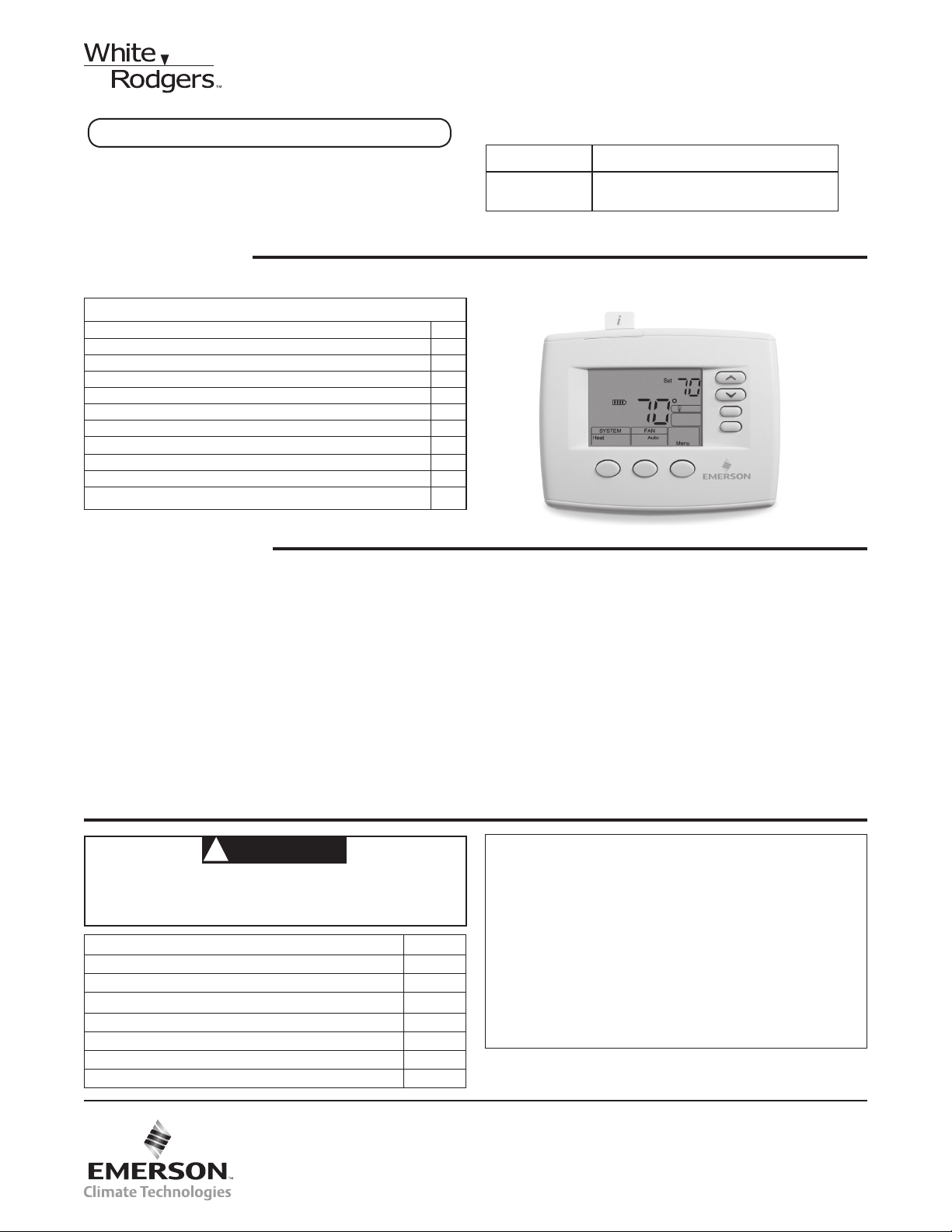
Blue 4” Universal Thermostat with
Automatic Heat/Cool Changeover Option
Single Stage, Multi-Stage or Heat Pump
Installation and Operating Instructions for Model:
Model Programming Choice
1F83-0471
Non-Programmable
THERMOSTAT APPLICATION GUIDE
Description
Heat Pump (No Aux. or Emergency Heat) Yes
Heat Pump (with Aux. or Emergency Heat) Yes
Systems with up to 2 Stages Heat, 2 Stages Cool Yes
Heat Only Systems (with optional fan switch) Yes
Millivolt Heat Only Systems – Floor or Wall Furnaces Yes
Cool Only Systems Yes
Gas or Oil Heat Yes
Electric Furnace
Hydronic (Hot Water) Zone Heat – 2 Wires Ye s
Hydronic (Hot Water) Zone Heat – 3 Wires Ye s
Compressor with Comfort Alert II Module (1F85CA only) Yes
Yes
1F83-0471 Thermostat
SPECIFICATIONS
Electrical Rating:
Battery Power .................................................... mV to 30 VAC, NEC Class II, 50/60 Hz or DC
Input-Hardwire ................................................... 20 to 30 VAC
Terminal Load ........................................................... 1.5 A per terminal, 2.5A maximum all terminals combined
Setpoint Range ......................................................... 45° to 90°F (7° to 32°C)
Rated Differentials: Fast Med. Slow
Heat (Single Stage/Multi Stage) ........................ 0.4 °F 0.6 °F 1.7 °F
Cool (Single Stage/Multi Stage) ........................ 0.9 °F 1.2 °F 1.7 °F
Heat Pump ......................................................... 0.9 °F 1.2 °F 1.7 °F
Aux. Heat ........................................................... 0.6 °F – 1.7 °F
Operating Ambient .................................................... 32° to +105°F (0° to +41°C)
Operating Humidity ................................................... 90% non-condensing max.
Shipping Temperature Range ................................... -40° to +150°F (-40° to +65°C)
Dimensions Thermostat ............................................ 3-7/8”H x 5-1/8”W x 1-1/4”D
CAUTION
!
To prevent electrical shock and/or equipment damage,
disconnect electric power to system at main fuse or
circuit breaker box until installation is complete.
Index Page
Installation 2
Wiring Connections 2
Wiring Diagrams 3
Thermostat Quick Reference 4
Installer Configuration Menu 5
Operating Your Thermostat 7
Troubleshooting 7
www.white-rodgers.com
www.emersonclimate.com
ATTENTION: MERCURY NOTICE
This product does not contain mercury. However, this product
may replace a product that contains mercury.
Mercury and products containing mercury must not be
discarded in household trash. Do not touch any spilled
mercury. Wearing non-absorbent gloves, clean up any
spilled mercury and place in a sealed container. For proper
disposal of a product containing mercury or a sealed
container of spilled mercury, place it in a suitable shipping
container. Refer to www.white-rodgers.com for location to
send product containing mercury.
PART NO. 37-7237A
1117
1
Page 2
INSTALLATION
Mounting
Hole
Mounting
Hole
Place Level
across
Mounting Tabs
(for appearance only)
Place Level
across
Mounting Tabs
(for appearance only)
WARNING
!
Thermostat installation and all components of the
control system shall conform to Class II circuits per
the NEC code.
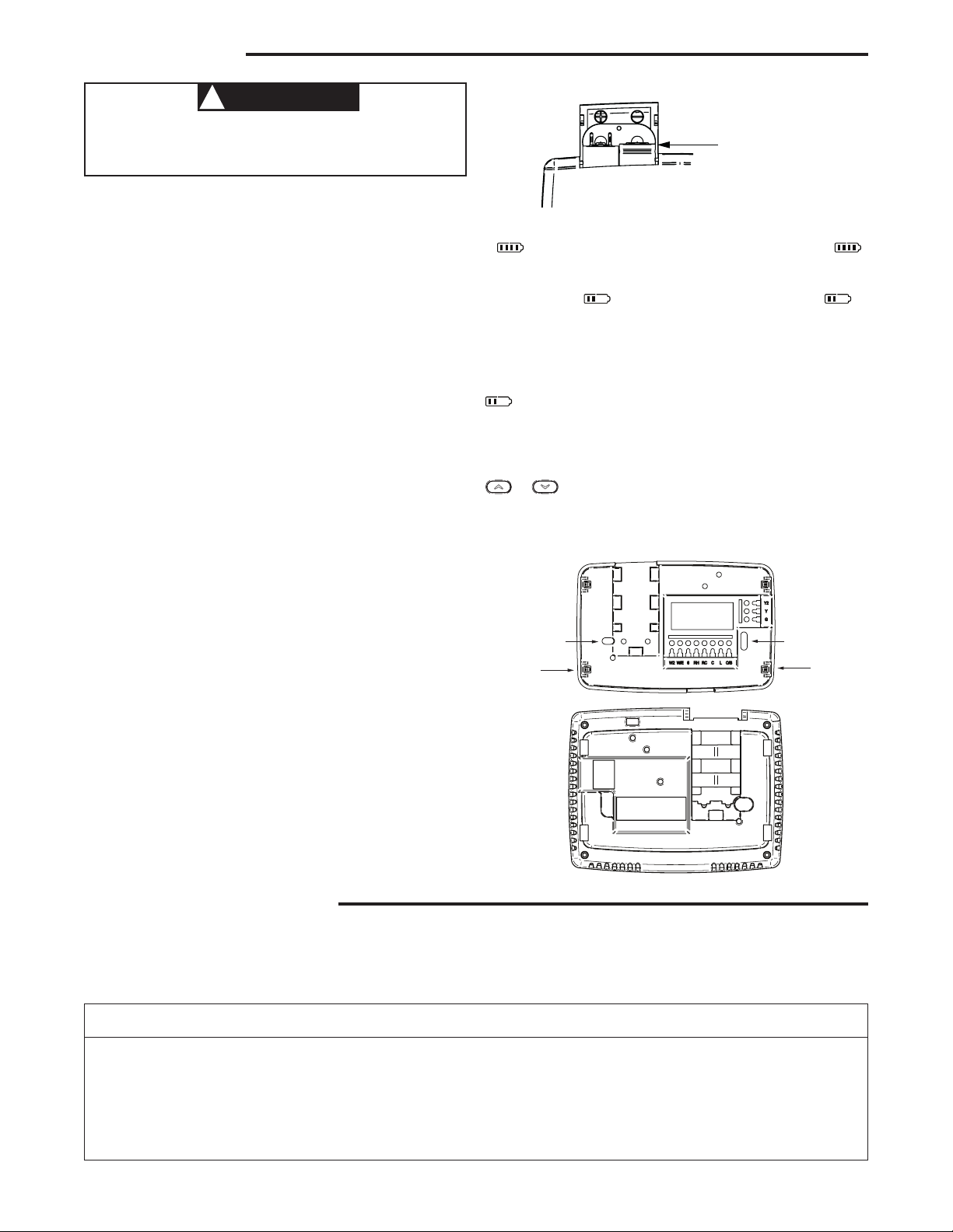
Remove Old Thermostat
A standard heat/cool thermostat consists of three basic parts:
1. The cover, which may be either a snap-on or hinge type.
2. The base, which is removed by loosening all captive
screws.
3. The switching subbase, which is removed by unscrewing
the mounting screws that hold it on the wall or adapter
plate. Before removing wires from old thermostat,
label each wire with the terminal designation from
which it was attached. Disconnect the wires from the
old thermostat one at a time. Do not let wires fall back
into the wall.
Installing New Thermostat
1. Pull the thermostat body off the thermostat base. Forcing
or prying on the thermostat will cause damage to the unit.
2. Place base over hole in wall and mark mounting hole
locations on wall using base as a template.
3. Move base out of the way. Drill mounting holes. If you
are using existing mounting holes and the holes drilled
are too large and do not allow you to tighten base snug ly, use plastic screw anchors to secure the base.
4. Fasten base snugly to wall using mounting holes shown
in Figure 2 and two mounting screws. Leveling is for
appearance only and will not affect thermostat operation.
5. Connect wires to terminal block on base.
6. Push excess wire into wall and plug hole with a fire re-
sistant material (such as fiberglass insulation) to prevent
drafts from affecting thermostat operation.
7. Carefully line the thermostat up with the base and snap
into place.
Figure 1 – Battery door shown open
“AA” Alkaline Batteries
Thermostat can be powered by system AC power or Battery.
If
is displayed, the thermostat is battery powered. If
is not displayed, thermostat is system powered with optional
battery back-up. When battery power remaining is approximately half, the
will be displayed. When “Change ”
is displayed, install fresh “AA” alkaline batteries immediately.
For best results, replace all batteries with new premium brand
alkaline batteries such as Duracell
®
or Energizer®. We recom-
mend replacing batteries every 2 years. If the home is going
to be unoccupied for an extended period (over 3 months) and
is displayed, the batteries should be replaced before
leaving. When less than two months of battery life remain, the
setpoint temperature will offset by 10 degrees (10 degrees
cooler in Heat mode / 10 degrees warmer in Cool mode). If
offset occurs, the normal setpoint can be manually reset with
or . Another offset will occur within two days if batter-
ies are not replaced.
Figure 2 – Thermostat base and rear view of thermostat
Batteries
2 “AA” alkaline batteries are included with the thermostat.
To install the batteries, pull the battery door as shown by the
arrow and lift open. Using the polarity indicated inside the battery door, insert the batteries. To close the battery door, swing
the door down while pulling in the direction of arrow. Once
fully down, snap the door back into position. To replace the
batteries, set system to OFF.
WIRING CONNECTIONS
Refer to equipment manufacturers’ instructions for specific
system wiring information. After wiring, see CONFIGURATION
section for proper thermostat configuration.
2
TERMINAL DESIGNATION DESCRIPTIONS
Terminal
Designation Description
L .............. Heat pump malfunction indicator for systems
with malfunction connection or Comfort Alert signal
O .............. Changeover valve for heat pump energized
constantly in cooling
B .............. Changeover valve for heat pump energized
constantly in heating
Y .............. Compressor Relay
Y2 ............. 2nd Stage Compressor
Refer to figure 3 through 6 for wiring diagram specifications.
Terminal
Designation Description
W/E ............Heat Relay/Emergency Heat Relay (Stage 1)
W2 .............2nd Stage Heat (3rd Stage Heat in HP 2)
G ..............Fan Relay
RH .............Power for Heating
RC .............Power for Cooling
C ..............Common wire from secondary side of cooling system
transformer or heat only system transformer
6...............3 Wire Zone Valve – Energized when no call for Heat
Page 3
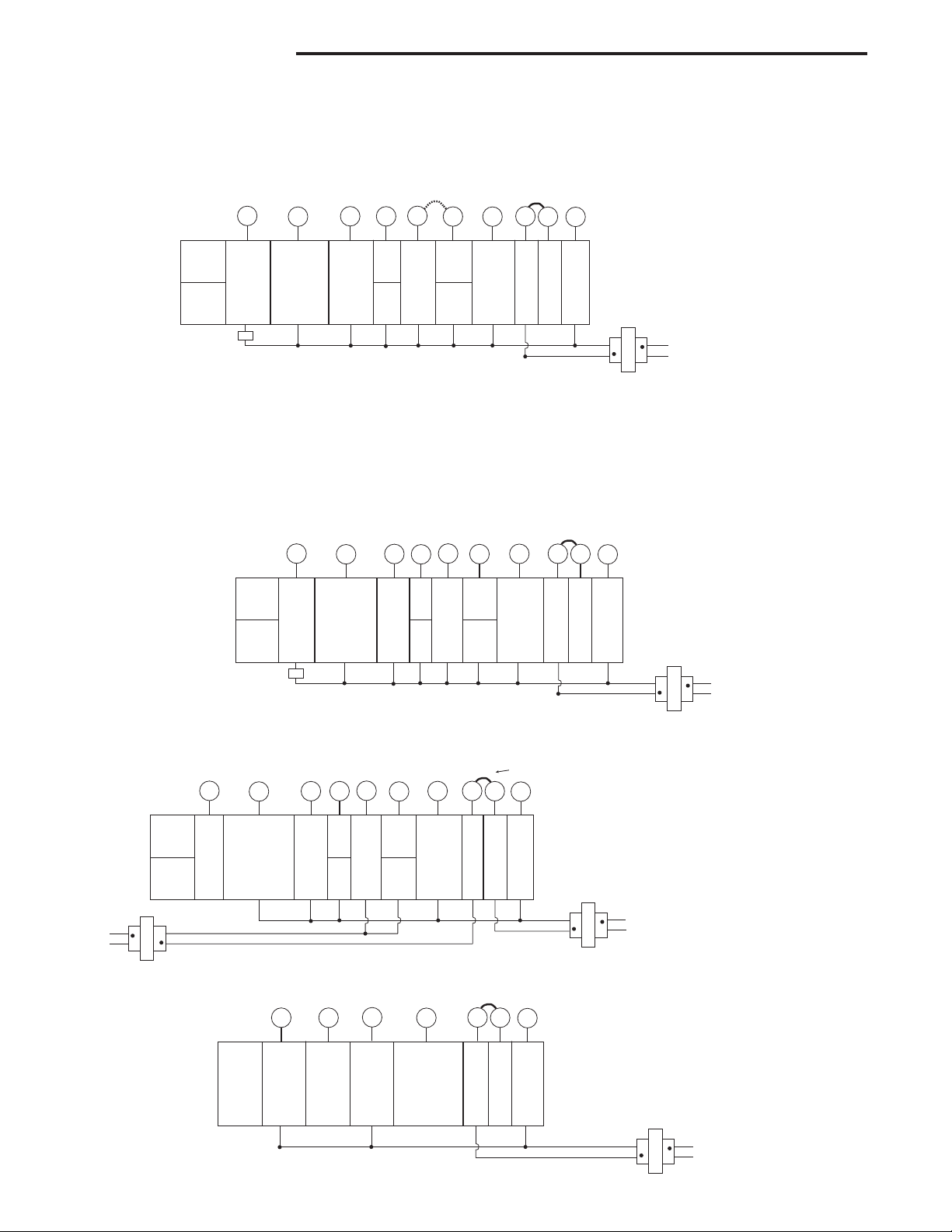
WIRING DIAGRAMS
Heat Pump Connections
If you do not have a heat pump system, refer to figures 4-6.
Refer to equipment manufacturers’ instructions for specific
system wiring information.
You can configure the thermostat for use with the following
heat pump systems.
System
Heat Pump 1
(HP1)
Heat Pump 2
(HP2)
Comfort Alert II Module
or Similar System
Malfunction Module
Figure 3 – Heat Pump Systems
L
Fault Indicator
or System
Malfunction
Switch
O/B
O
Energized in
Cool Mode
B
Energized in
Heat, Off,
Emergency
Mode
Y
Heat and
Cool Mode
1st Stage
(Compressor)
Y2
No
Output
2nd
Stage
(Com-
pressor)
W/E
Emergency
Mode
1st Stage
Jumper
Heat Mode
2nd Stage.
Emergency
Mode 2nd
Heat Mode
3rd Stage.
Emergency
Mode 2nd
Single Stage and Multi-Stage Connections
Refer to equipment manufacturers’ instructions for specific
system wiring information.
This thermostat is designed to operate a single-transformer
or two-transformer system.
You can configure the thermostat for use with the following
fossil fuel systems:
Figure 4 – Single Stage or Multi-Stage System (No Heat Pump) with Single Transformer
L
System
Single
Stage 1
(SS1)
Multi-
Stage 2
(MS2)
Comfort Alert II Module
or Similar System
Malfunction Module
Fault
Indicator
or
System
Malfunction
Switch
O/B
O
Energized Constantly
in Cool Mode
B
Energized Constantly
in Heat, Off,
Emergency
Mode
Y
Cool Mode
1st Stage
Y2
No
Output
Cool
Mode
2nd
Stage
Heat
Mode
1st Stage
HEAT PUMP TYPE 1 (HP 1). Single stage compressor
system; gas or electric backup.
HEAT PUMP TYPE 2 (HP 2). Multi-stage compressor or two
compressor system with gas or electric backup.
After wiring, see INSTALLER CONFIGURATION section for
proper thermostat configuration.
Jumper
C
W2
G
RC
RH
NOTE: If your system does
not provide an E connection,
jumper W2 to W/E to use
the Auxiliary Heat in the
Emergency Mode.
* Common connection
required for fault or
malfunction indication.
120VAC
Stage
Stage
Blower/
Circulator
Fan Energized
on Call for
Heat or Cool.
Set Elect/Gas
Option for
Emergency
Mode
24 Volt
(Hot)
Heat
24 Volt
(Hot)
Cool
Optional*
24 Volt
(Com-
mon)
NEUTRAL
24VAC
HOT
CLASS II
TRANSFORMER
SINGLE STAGE (SS 1) gas, oil or electric.
MULTI-STAGE (MS 2) gas, oil or electric.
After wiring, see INSTALLER CONFIGURATION section for
proper thermostat configuration.
Jumper
W/E
No Output
Heat Mode
2nd Stage
W2
G
Blower/
Circulator
Fan Energized
on Call for
Cool (and
Heat if
configured
for Electric
Heat)
RH
24 Volt
(Hot)
Heat
RC
24 Volt
(Hot)
Cool
C
Optional*
24 Volt
(Com-
mon)
NEUTRAL
24VAC
HOT
* Common connection
required for fault or
malfunction indication.
120VAC
CLASS II
TRANSFORMER
120VAC
HEATING
CLASS II
TRANSFORMER
Figure 5 – Single Stage or Multi-Stage System (No Heat Pump) with Two Transformers
Remove Jumper Wire
Jumper
between RH & RC
System
Single
Stage 1
(SS1)
Multi-
Stage 2
(MS2)
NEUTRAL
24VAC
HOT
L
Fault
Indicator
(NOT
USED)
O/B
O
Energized Constantly
in Cool Mode
B
Energized Constantly
in Heat, Off,
Emergency
Mode
Y
Cool Mode
1st Stage
Y2
No
Output
Cool
Mode
2nd
Stage
W/E
Heat
Mode
1st Stage
W2
No Output
Heat Mode
2nd Stage
Fan Energized
G
Blower/
Circulator
on Call for
Cool (and
Heat if
configured
for Electric
Heat)
RH
24 Volt
(Hot)
Heat
RC
24 Volt
(Hot)
Cool
C
Optional
24 Volt
(Com-
mon)
NEUTRAL
24VAC
HOT
CLASS II
TRANSFORMER
120VAC
COOLING
Figure 6 – 3-Wire (SPDT) Heat Only Zone Valve Wiring
Jumper
W
Y
Opens
Valve
(4)
G
Blower/Circulator
Fan Energized
RH
24 Volt
(Hot)
Heat
(5)
RC
24 Volt
(Hot)
Cool
C
Constant
24 Volt
(Common)
NEUTRAL
24VAC
HOT
CLASS II
TRANSFORMER
System
Single Stage
3-wire
Zone Valve
application
6
Closes
Valve
(6)
NOTE: If continuous backlight or
hardwired power input are desired but
do not function in both HEAT and COOL
modes, cut the heating transformer 24V
wires and tape off. Connect the neutral
circuit disconnected from the heating
transformer to the neutral circuit of the
cooling transformer. Disconnect the wire
to the RH terminal and install a jumper
between RH and RC. Depending on
the system requirements, replace the
cooling transformer with a 75VA class II
transformer if needed.
120VAC
3
Page 4
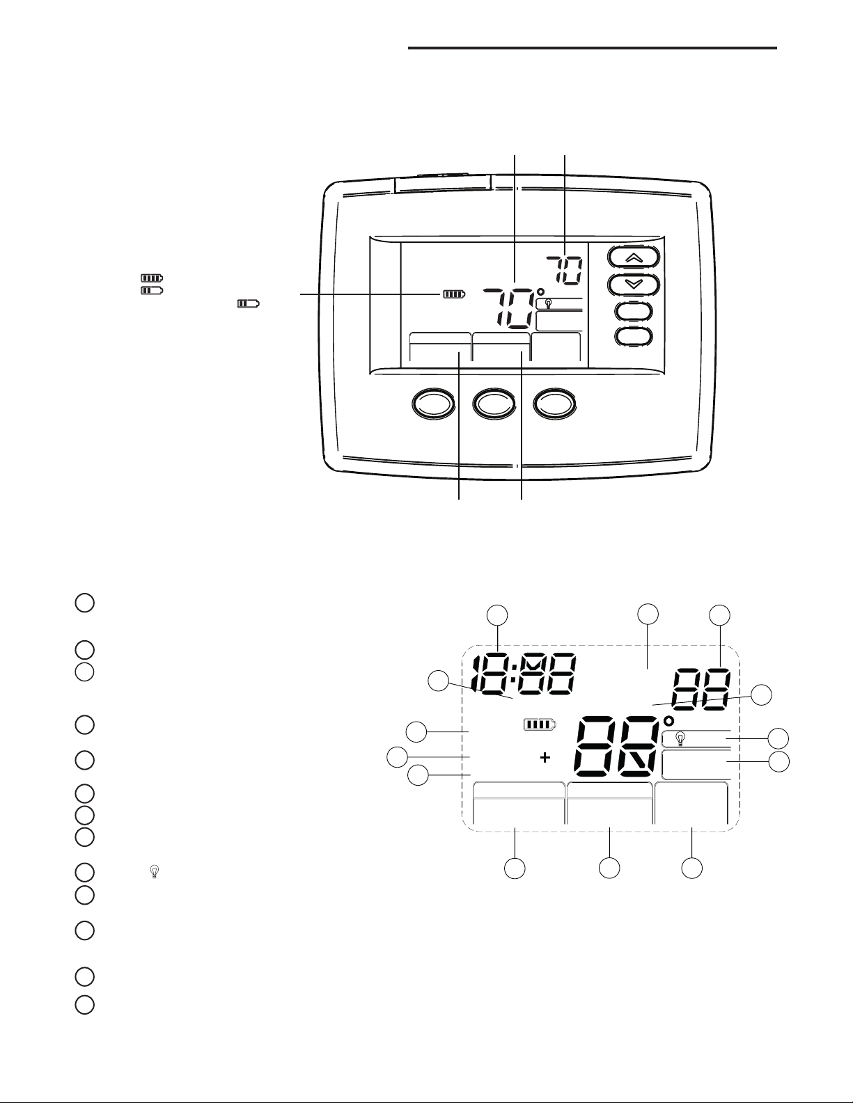
Room
Setting
THERMOSTAT QUICK REFERENCE
Home Screen Description
Figure 7 – Home Screen Display
Displays the power level of
the 2 “AA” batteries:
indicates good power level
indicates batteries at about
half power. “Change ” indicates
batteries are low and should be
replaced with 2 new premium brand
“AA” Alkaline batteries.
(See page 2 for more details)
Heat
SYSTEM
System
Indicator
Temperature
Set
FAN
Auto
Fan
Indicator
Temperature
Menu
Programming and Configuration Items
“System On” indicates when heating or cooling stage
1
is energized. “+2” flashing indicates when a second
stage is energized, +2 not flashing when “Aux” is energized.
2
The word “Set” indicates the setpoint temperature.
Displays “Change Filter” when the system has run
3
for the programmed filter time period as a reminder to
change or clean your filter.
Displays System Mode (Heat, Emer, Auto, Cool, Off)
4
in Menu Mode.
5
Displays Fan Mode (On, Auto) or “Run Sched” in
Menu Mode.
6
Displays “Menu”.
7
Displays “Save” when Cool Savings
Displays “Heat Pump” to indicate thermostat is config-
8
TM
is working.
ured for Heat Pump.
9
Displays
“Cool Savings” when in the Cool Mode if Cool Savings
10
(light bulb) in non-programmable mode.
has been enabled in the menu.
“Call For Service” indicates a fault in the heating/
11
cooling system, it does not indicate a fault in the
thermostat.
12
Flashes “LOC” when keypad lockout is enabled.
In Configuration Menu, shows screen number. If blank,
13
thermostat is earlier model and requires instruction sheet
37-7149B.
Figure 8 – Programming & Configuration Items
12 13
2
Mo Tu We Th Fr Sa Su
11
3
1
8
Month Call For Service
Change
Filter
System On 2
Heat Pump
SYSTEM
Heat Emer Auto
Cool O Time
P Date
Temp
On Auto
Run Sched
4
FAN
5
Save
Set
Cool Savings
Schedule
Year
Hold
Auto Sched
Run
Menu
6
7
9
10
4
Page 5
INSTALLER/CONFIGURATION MENU
To enter the Configuration Menu, SYSTEM must be set to HEAT, COOL or EMER. Press the Menu button for at least 5
seconds. The display will show item #1 in the table below. Press Menu button to advance to the next menu item. Press
to change a menu item.
INSTALLER/CONFIGURATION MENU
MENU
SCREEN
NUMBER
01
02
03
04
05
06
07
08
09
10
11
12
13
14
15
16
17
18 HP2
19
20
21
22
MS/SSPRESS
HP
BUTTON
MENU (Off)
MENU (000) Lk 001 to 999 Selects Keypad lockout combination number
MENU (MS 2) HP 1, HP 2, SS 1 Selects Multi-Stage (MS 2 No Heat Pump),
MENU (GAS) for SS or MS
MENU (0) CS 1, 2, 3, 4, 5, 6 Selects Cool Savings
MENU (ME)
MENU (ME)
MENU (ME)
MENU (FA)
MENU (OFF) CL CL On Compressor Lockout Time Delay
MENU Heat Auto
MENU (On) dL dL OFF Selects Display Light On or OFF
MENU 0
MENU
MENU (90) L Heat L 62 to L 89 Selects Limited HEAT Range
MENU (45) L Cool L 46 to L 82 Selects Limited COOL Range
MS MENU (On) Heat FA OFF Fast Heat option may be disabled by
MENU (On) Cool FA OFF Fast Cool option may be disabled by
MENU (OFF) CA On Selects active Comfort Alert On or OFF.
MENU (OFF) Change Filter On Selects Filter Change-out Indicator On or OFF.
MENU (200 h) Change Filter 25-1975 h Change Filter time in 25 hour increments. This
MENU (o) Cool On (b) Heat On Selects operation of the reversing valve termi-
DISPLAYED
(FACTORY DEFAULT)
Lk
(ELE) for HP
CR Heat
CR Cool
CR Heat Pump
CR Emer
Cool Off
(current temperature)
°F °C
Press
to select from listed
or
options
L Total Keypad lockout
ELE or
GAS
SL, FA Adjustable Anticipation:
SL, FA
SL, FA Adjustable Anticipation (Heat Pump) (only
SL, FA
SL
Heat Cool Off,
Heat Off with Fan icon,
Heat Off without Fan icon,
Cool Off, Auto Off
1 HI, 2 HI, 3 HI, 4 HI,
1 LO, 2 LO, 3 LO, 4 LO
COMMENTS
(Not available on earlier models)
Heat Pump 1 (HP 1, 1 compressor), or
Single Stage (SS 1), Heat Pump 2 (HP 2,
2 compressor or 2 speed compressor)
GAS setting: furnace controls the blower
ELE setting: thermostat controls the blower
Value 1 (low) to 6 (high),
Value 0 Disables Feature
Selects heating cycle rate for MS or SS
Adjustable Anticipation:
Selects cool cycle rate
when heat pump selected in #1)
Selects the cycle rate for Emergency
mode and Auxiliary stage if Heat Pump
is selected in item 1.
Select System Switch Conguration
with Automatic Changeover capability.
Adjustable Ambient Temperature Display
Selects Fahrenheit/Celsius
Temperature Display
selecting OFF. NA to SS cong.
NA to Cool only system.
selecting OFF. NA to SS cong.
NA to Heat only system.
Requires CA II Module.
(Not available on earlier models)
menu only appears if On is selected in above.
nal (O/B) output as an O or B terminal.
or
5
Page 6

INSTALLER/CONFIGURATION MENU
1 & 2)Keypad Lockout – This menu selection will display
“Lk” and “OFF” (default, keypad not locked out). The
and are used to toggle the selection between
“OFF” and “L” (keypad locked out). When the keypad
lockout selection is enabled “L”, and the MENU button
is pressed again, the display will indicate the number
“0” (default, still disabled) in the time digits. The
and
to 999. If a combination of 0 is selected and the MENU
button is pressed, the menu will be exited and keypad
will not be locked. If 1 to 999 is selected and the MENU
button is pressed, the combination is stored into memory
and the menu is exited. The “Loc” will display designating keypad locked with a valid combination. The SYSTEM
button will operate for 10 seconds after the menu mode
is exited to allow the user to change the mode from OFF
to the desired SYSTEM mode.
While the keypad is locked out, a press of MENU will en-
ter the configuration menu. The first menu item displayed
is the combination code “0”. The
used to set the combination unlock number from 0 to
999. If the unlock number matches exactly with the combination lock number stored in memory when the MENU
button is pressed, the keypad is unlocked and the “Loc”
is removed. If the unlock number does not match when
the MENU button is pressed, the combination returns to
“0” for another attempt to set the unlock code. To exit the
menu, without unlocking the keypad, press RUN SCHED.
To reset the combination code and unlock the keypad if
the code is forgotten, see troubleshooting section.
3) This control can be configured for:
MS 2 – Multi-Stage System (no heat pump)
HP 1 – Heat Pump with one stage of compressor
HP 2 – Heat Pump with two stage compressor or two
compressor system, Gas or Electric backup
SS 1 – Single Stage System
4) GAS or Electric (ELE) fan operation. If the heating system requires the thermostat to energize the fan, select
ELE. Select GAS if the heating system energizes the fan
on a call for heat.
5) Select Cool Savings™ value – Selects the amount
of adjustment for the Cool Savings™ feature in Cool
mode with 1 (1°) being the least amount of adjustment
and 6 (6°) being the most amount of adjustment. Default
value is 0 which disables this feature. Selecting a value
greater than 0 will display Cool Savings on the screen
and enable the key for Cool Savings feature. Cool Savings is an optional energy saving feature that can reduce
your cooling costs. It is based on the principal that lower
indoor humidity makes a slightly higher temperature
feel more comfortable. Cool Savings operates during
periods of high demand which normally occur on the
hottest summer days when a cooling system may run
for hours to reach the thermostat setting. Long cooling
run times also lower the indoor humidity. Cool Savings,
very slowly, adjusts the setpoint temperature to make the
setpoint closer to the displayed room temperature, to a
maximum of the number of degrees you select. Adjusting the setpoint temperature over a long cooling run time
allows the system to reach your set temperature and turn
off. The room temperature will actually be higher than
the thermostat displays but the reduction in humidity will
allow comfort at the slightly higher temperature.
To turn this feature on in the Cool mode press Cool
Savings. The display will show “Save” next to the
setpoint temperature. When Cool Savings is making adjustments to the room temperature display “Save” will be
flashing and the displayed room temperature may vary
within the adjustment range you selected.
are used to set the combination number from 0
or keys are
If “Save” is not displayed and this feature is OFF, no
change will occur when the cooling system is continuously running during periods of high demand.
6, 7, 8 & 9) Cycle Rate Selection – The factory default set-
ting for Heat and Cool modes, SS1, MS2, is medium
cycle (ME). For Heat Pump, HP1, HP2, the default setting is medium (ME). For Emer (Aux) the default setting
is fast cycle (FA). To change cycle rate, press the
key.
Cycle rate differentials for different settings are:
Fast Medium Slow
MODE FA ME SL
Heat (SS1, MS2) 0.4°F 0.6°F 1.7°F
Cool (SS1, MS2) 0.9°F 1.2°F 1.7°F
Heat Pump (HP1, HP2) 0.9°F 1.2°F 1.7°F
Emer (HP1, HP2) 0.6°F - 1.7°F
10) Select Compressor Lockout CL OFF or ON – Select-
ing CL ON will cause the thermostat to wait 5 minutes
between cooling cycles. This is intended to help protect
the compressor from short cycling. Some newer com-
pressors already have a time delay built in and do not
require this feature. Your compressor manufacturer can
tell you if the lockout feature is already present in their
system. When the thermostat compressor time delay oc-
curs, it will flash the setpoint for up to five minutes.
11) System Mode Configuration – This thermostat is
configured for Heat and Cool (SYSTEM switch with Cool,
Off, Heat) default. It can also be configured for Heat and
Cool with Auto changeover (Heat, Auto, Cool, Off), Heat
only with fan (Off, Heat), Heat only without fan, Auto only
(Auto, Off), and Cool only (Cool, Off).
12) Select Backlight Display – The display backlight im-
proves display contrast in low lighting conditions. When
the “C” terminal is powered, selecting backlight CdL ON
will keep the light on continuously. Select backlight OFF
will turn the light on momentarily after any key is pressed.
When the “C” terminal is not powered, the light will be on
momentarily after any key is pressed no matter whether
the backlight is selected ON or OFF.
13) Select Temperature Display Adjustment 4 LO to 4 HI
– Allows you to adjust the room temperature display up
to 4° higher or lower. Your thermostat was accurately cali-
brated at the factory, but you have the option to change
the display temperature to match your previous thermo-
stat. The current or adjusted room temperature will be
displayed.
14) Select F° or C° Readout – Changes the display readout
to Celsius or Fahrenheit as required.
15 & 16) Temperature Limit Range Heat or Cool – This
selection sets the maximum HEAT (13) or minimum
COOL (14) temperature for the setpoint range. Select the
limit temperature using the
Schedule mode, the setpoint temperature will not adjust
past the limit temperature selected. When the limit tem-
perature is reached, trying to raise or lower the setpoint
past the limit will cause “L” to be displayed in the times
digits for about 6 seconds. This feature is not available on
earlier models.
17 & 18) Select Fast Second Stage ON or OFF – Heat
pump or Multi-stage only, in the run mode, with the fast
Heat feature enabled (FA Heat On), if the Heat setpoint
temperature is manually raised by 3°F (2°C) or more
above the actual temperature using
stage will energize immediately. With FA OFF, second
stage will not energize until the setpoint temperature is
1°F or more above actual temperature for more than ten
minutes. The Fast Cool feature (FA Cool) provides the
same controls when the setpoint temperature is lowered.
or keys. In the Run
the second
or
6
Page 7

INSTALLER/CONFIGURATION MENU
19) Comfort Alert with Active Protection – Turn this
feature ON to enable active protection. This allows the
thermostat to identify fault codes sent by the Comfort
Alert module when compressor damage is possible and
react to those codes by turning the compressor off. Fault
codes from the Comfort Alert module will flash on the
thermostat. (Refer to Comfort Alert Yellow Alert Codes
in Troubleshooting section.) If a Comfort Alert module is
not connected, or to disable active protection, turn this
feature OFF. If a Comfort Alert module is connected and
this feature is turned OFF, the thermostat will still receive
and flash the fault codes from the Comfort Alert module,
but the active protection will not be enabled to protect the
compressor.
20 & 21) Select Filter Replacement Reminder and Set
Run Time – Select the “Change Filter” reminder On
or OFF. If selected On, press MENU to select the time
OPERATING YOUR THERMOSTAT
Choose the Fan Setting (Auto or On)
Press the FAN button to Auto or On.
Fan Auto is the most commonly selected setting and runs the
fan only when the heating or cooling system is on.
Fan On runs the fan continuously for increased air circulation
or to allow additional air cleaning.
Choose the System Setting
(Heat, Off, Cool, Auto, Emer)
Press the SYSTEM button to select:
Heat: Thermostat controls only the heating system.
Off: Heating and Cooling systems are off.
Cool: Thermostat controls only the cooling system.
Auto: Auto Changeover is used in areas where both heating
and cooling may be required on the same day. AUTO allows
the thermostat to automatically select heating or cooling
depending on the indoor temperature and the selected heat
and cool temperatures. When using AUTO, be sure to set the
Cooling temperatures more than 1° Fahrenheit higher than
the heating temperature.
Emer: (Heat Pump models) Thermostat controls only backup
heating system.
period from 25 to 1975 hours in 25 hours increments.
In a typical system, 200 hours (default) of run time is
approximately 30 days. After the selected time of blower
operation, the thermostat will display “Change Filter”
as a reminder to change or clean your air filter. When
“Change Filter” is displayed, press MENU or RUN
SCHED button to clear the display and restart the time to
the next filter change.
22) Select Reversing Valve Output – The O/B option is
factory set at “O” position. This will accommodate the
majority of heat pump applications, which require the
changeover relay to be energized in COOL. If the
thermostat you are replacing or the heat pump being
installed with this thermostat requires a “B” terminal, to
energize the changeover relay in HEAT, the O/B option
should be set at “B” position.
IMPORTANT!
Second Stage Time Delay
Your thermostat is designed to determine the optimum time
to activate the second stage. Simply raising the temperature
in heating or lowering it in cooling will not always force the
thermostat to bring the second stage on quickly. There is a
time delay from 0-30 minutes depending on the performance
of the first stage of the system.
EXAMPLE: For the last 2 hours the thermostat is set on 70°
and the room temperature is 70° with the equipment using
only the first stage of heat. Since the equipment is keeping
the temperature within 1° of setpoint, the thermostat will
delay second stage for a longer time if you manually raise the
temperature or if the room temperature quickly changes. Once
the second stage comes on, it will come on sooner the next
time there is a difference between the setpoint and the room
temperature. The net effect of the staging program is that when
the first stage is capable of making temperature the second
stage will delay longer. When the thermostat calculates that
first stage cannot make temperature in a reasonable time,
the second stage will come on sooner. This built in function
automatically optimizes the use of additional stages of heat
or cool.
Manual Operation for Non-Programmable Mode
Press the SYSTEM button to select Heat or Cool and use
the
desired setting. After selecting your desired settings you can
also press the SYSTEM button to select AUTO to allow the
thermostat to automatically change between Heat and Cool.
or buttons to adjust the temperature to your
TROUBLESHOOTING
Comfort Alert Codes
The Comfort Alert diagnostics product monitors the air conditioning outdoor systems with single phase Copeland Scroll
compressors. Abnormal system and electrical conditions are
indicated by flashing ALERT codes on the yellow LED on the
Comfort Alert module. The flash codes are transmitted to the
thermostat by the Comfort Alert Thermostat interface module.
The Comfort Alert compatible thermostat displays “Call For
Service” that flashes at the same rate as the yellow LED on
the Comfort Alert module.
Comfort Alert Yellow Alert Codes
1 Flash Long run time
2 Flashs System pressure trip
3 Flashs Short cycling
4 Flashs Locked rotor
5 Flashs Open circuit
6 Flashs Open start circuit
7 Flashs Open run circuit
8 Flashs Welded Contactor
9 Flashs Low voltage
7
Page 8

TROUBLESHOOTING
Reset Operation
Note: When thermostat is reset, installer configuration menu
settings and programming will reset to factory settings.
If a voltage spike or static discharge blanks out the display
or causes erratic thermostat operation, you can reset the
thermostat by removing the wires from terminals R and C
(do not short them together) and removing batteries for 2
minutes. After resetting the thermostat, replace the wires and
batteries. If the thermostat has been reset and still does not
function correctly contact your heating/cooling service person
or place of purchase.
Note: Be sure to review the installer configuration menu
settings.
To reset the programming, clock and configuration settings,
press
and and the FAN button simultaneously. The
thermostat should go blank and then all segments will be
displayed momentarily.
Symptom Possible Cause Correction Action
No Heat/No Cool/No Fan
(common problems)
No Heat
No Cool
Heat, Cool or Fan
Runs Constantly
Thermostat Setting &
Thermostat Thermometer
Disagree
Furnace (Air Conditioner)
Cycles Too Fast or Too
Slow (narrow or wide
temperature swing)
Forgot Keypad
Lockout Code
Thermostat does not have
Menu Screen Numbers
1. Blown fuse or tripped circuit breaker.
2. Furnace power switch to OFF.
3. Furnace blower compartment door or panel
loose or not properly installed.
4. Loose connection to thermostat or system.
1. Pilot light not lit.
2. Furnace Lock-Out Condition. Heat
may also be intermittent.
3. Heating system requires service or
thermostat requires replacement.
1. Cooling system requires service or
thermostat requires replacement.
1. Possible short in wiring.
2. Possible short in thermostat.
3. Possible short in heat/cool/fan system.
4. FAN Switch set to Fan ON.
1. Thermostat thermometer setting
requires adjustment.
1. The location of the thermostat and/or
the size of the Heating System may
be influencing the cycle rate.
1. Earlier version of thermostat. Refer to Instruction Sheet 37-7149B
Replace fuse or reset breaker.
Turn switch to ON.
Replace door panel in proper position to engage safety
interlock or door switch.
Tighten connections.
Re-light pilot.
Many furnaces have safety devices that shut down when
a lock-out condition occurs. If the heat works intermittently
contact the furnace manufacturer or local HVAC service
person for assistance.
Diagnostic: Set SYSTEM Switch to HEAT and raise the
setpoint above room temperature. Within a few seconds
the thermostat should make a soft click sound. This sound
usually indicates the thermostat is operating properly. If the
thermostat does not click, try the reset operation listed above.
If the thermostat does not click after being reset contact your
heating and cooling service person or place of purchase for
a replacement. If the thermostat clicks, contact the furnace
manufacturer or a HVAC service person to verify the heating
is operating correctly.
Same as diagnostic for No Heat condition except set the
thermostat to COOL and lower the setpoint below the room
temperature. There may be up to a five minute delay before
the thermostat clicks in Cooling.
Check each wire connection to verify they are not shorted or
touching together. No bare wire should stick out from under
terminal block. Try resetting the thermostat as described
above. If the condition persists the manufacturer of your
system or service person can instruct you on how to test
the Heat/Cool system for correct operation. If the system
operates correctly, replace the thermostat.
The thermometer can be adjusted +/- 4 degrees. See
Temperature Display Adjustment in the Configuration Menu
section.
Digital thermostats provide precise control and cycle faster
than older mechanical models. The system turns on and off
more frequently but runs for a shorter time so there is no
increase in energy use. If you would like an increased cycle
time, choose SL for slow cycle in the Configuration menu,
step 6 (heat), 7 (cool) or 8 (heat pump). If an acceptable cycle
rate is not achieved, contact a local HVAC service person for
additional suggestions.
Hold MENU key for 20 seconds and the lockout will reset.
White-Rodgers is a division
of Emerson Electric Co.
The Emerson logo is a
trademark and service mark
of Emerson Electric Co.
HOMEOWNER HELP LINE: 1-800-284-2925
www.white-rodgers.com
www.emersonclimate.com
Page 9

www.emersonclimate.com
www.white-rodgers.com
LÍNEA DE AYUDA PARA EL USUARIO: 1-800-284-2925
1. Version anterior del termostato. Refiérase al manual 37-7149B.
se restablecerá.
Presione el botón MENU durante 20 segundos y el bloqueo
especializado para obtener sugerencias adicionales.
aceptable, póngase en contacto con personal técnico
u 8 (bomba de calor). Si no alcanza una velocidad de ciclo
ciclo lento en el menú de configuración, paso 6 (calor), 7 (frío)
Si desea aumentar el tiempo de un ciclo, seleccione SL para un
más corto por lo que no hay aumento en el consumo de energía.
apaga con más frecuencia pero funciona durante un período
modelos mecánicos más antiguos. El sistema se enciende y se
preciso y pueden reiniciar el ciclo más rápidamente que algunos
Los termostatos digitales proporcionan un control de temperatura
la temperatura visualizada en la sección Menú de configuración.
El termómetro puede ajustarse en +/- 4 grados. Vea el Ajuste de
correctamente, cambie el termostato.
frío/calor está funcionando correctamente. Si el sistema funciona
personal técnico podrá indicarle cómo probar si el sistema de
abajo. Si la condición persiste, el fabricante de su sistema o el
terminales. Intente reajustar el termostato como se describe más
sobresalir ningún cable pelado por debajo de los tornillos
de que no estén en cortocircuito o tocándose entre sí. No debe
Verifique todas las conexiones de los cables para asegurarse
minutos en pasar al modo de enfriamiento.
temperatura ambiente. El termostato puede tardar hasta cinco
y coloque la temperatura de referencia por debajo de la
el sistema no calienta pero coloque el termostato en COOL
Siga el mismo procedimiento de diagnóstico que Cuando
para verificar que la calefacción esté funcionando correctamente.
contacto con el fabricante del calefactor o con el personal técnico
un reemplazo. Si el termostato hace un chasquido, póngase en
calefacción y enfriamiento o con el lugar de compra para obtener
póngase en contacto con su personal de servicio técnico de
Si el termostato no hace un chasquido después de reajustarlo,
chasquido, intente la operación de reajuste arriba indicada.
termostato está funcionando correctamente. Si no se oye un
suave del termostato. Por lo general, este sonido indica que el
ambiente. En cuestión de segundos, debería oírse un chasquido
la temperatura de referencia por encima de la temperatura
Diagnostico: Ajuste el interruptor SYSTEM en HEAT y suba
solicitar ayuda.
fabricante de la caldera o con el personal técnico local para
funciona de manera intermitente, póngase en contacto con el
cuando se produce una condición de bloqueo. Si la calefacción
Muchas calderas tienen dispositivos de seguridad que se cierran
Vuelva a encender el piloto.
Ajuste las conexiones.
o de la puerta.
que se enganche con el interruptor de interbloqueo de seguridad
Vuelva a colocar el panel de la puerta en el lugar correcto para
Coloque el interruptor en ON.
Cambie el fusible o vuelva a activar el disyuntor.
en la duración de los ciclos.
del sistema de calefacción pueden influir
1. La ubicación del termostato y/o el tamaño
requiere ajuste.
1. El valor del termómetro del termostato
4. El interruptor FAN está en Fan ON.
de calor/frío/ ventilador.
3. Posible cortocircuito en el sistema
2. Posible cortocircuito en el termostato.
1. Posible cortocircuito en los cables.
técnico o debe cambiarse el termostato.
1. El sistema de enfriamiento requiere servicio
técnico o debe cambiarse el termostato.
3. El sistema de calefacción requiere servicio
El calor también puede ser intermitente.
2. Condición de bloqueo del calefactor.
1. La luz piloto no está encendida.
está suelta.
4. La conexión al termostato o al sistema
están debidamente instalados.
soplador del calefactor están sueltos o no
3. La puerta o el panel del compartimento del
está en OFF.
2. El interruptor de alimentación del calefactor
1. Se quemó el fusible o se disparó el disyuntor.
servicio de Emerson Electric Co.
marca comercial y una marca de
El logotipo de Emerson es una
de Emerson Electric Co.
White-Rodgers es una división
del menu
numerous de la pantalla
El termostato no tiene los
bloqueo del teclado
Olvidó el código de
amplia de la temperatura)
(oscilación reducida o
o demasiado cortos
son demasiado largos
aire acondicionado
Los ciclos del calefactor/
coincide con el termómetro
El ajuste del termostato no
manera constante
ventilador funciona de
El modo de calor, frío o
El sistema no enfría
El sistema no calienta
(problemas comunes)
No funciona el ventilador
El sistema no enfría/
El sistema no calienta/
Síntoma Causa posible Acción correctiva
se iluminarán durante unos instantes.
termostato debería ponerse en blanco y luego, todos los segmentos
y el botón FAN simultáneamente. La pantalla del
Para reajustar la programación, el reloj y la configuración, presione
de configuración.
Nota: asegúrese de revisar los ajustes del menú instalador/
de calefacción/enfriamiento o con el lugar donde realizó la compra.
funciona correctamente, póngase en contacto con su servicio técnico
cables y las pilas. Si el termostato se ha reajustado pero aún no
2 minutos. Después de reajustar el termostato, vuelva a colocar los
terminales R y C (no los cortocircuite) y retirando las pilas durante
errática, puede reajustar el termostato retirando los cables de las
blanco la pantalla o hace que el termostato funcione de manera
de fábrica. Si un pico de voltaje o una descarga estática pone en
instalador/de configuración y la programación volverán a los ajustes
Nota: una vez reajustado el termostato, la configuración del menú
Operación de reajuste
SOLUCIÓN DE PROBLEMAS
Page 10

7
9 parpadeos Bajo voltaje
8 parpadeos Contactor soldado
7 parpadeos Circuito de funcionamiento abierto
6 parpadeos Circuito de inicio abierto
5 parpadeos Circuito abierto
4 parpadeos Rotor bloqueado
3 parpadeos Ciclo corto
2 parpadeos Disparo de presión del sistema
Tiempo de funcionamiento prolongado
1 parpadeo
Códigos de alerta amarilla del alerta de comodidad
el uso de etapas adicionales de calor o frío.
activará antes. Esta función incorporada optimiza automáticamente
temperatura dentro de un tiempo razonable, la segunda etapa se
el termostato calcula que la primera etapa no puede llegar a la
temperatura, la segunda etapa se demorará más tiempo. Cuando
por etapas es que cuando la primera etapa es capaz de alcanzar la
de referencia y la temperatura ambiente. El efecto neto del programa
antes la próxima vez que haya una diferencia entre la temperatura
rápidamente. Una vez que se activa la segunda etapa, se activará
manualmente la temperatura o si la temperatura ambiente cambia
el termostato demorará la segunda etapa un tiempo más si sube
temperatura dentro de 1 grado de la temperatura de referencia,
la primera etapa de calor. Como el equipo está manteniendo la
y suba la temperatura ambiente es de 70°, y el equipo utiliza sólo
EJEMPLO: Durante las últimas 2 horas el termostato está en 70°
minutos según el rendimiento de la primera etapa del sistema.
entre rápidamente en la segunda etapa. Hay una demora de 0–30
la temperatura de refrigeración no siempre hará que el termostato
activar la segunda etapa. Subir la temperatura de calefacción o bajar
Su termostato está diseñado para determinar el tiempo óptimo para
Demora de tiempo de la segunda etapa
termostato cambie automáticamente entre calor y frío.
el botón SYSTEM para seleccionar AUTO para permitir que el
de seleccionar los valores deseados también puede presionar
o para ajustar la temperatura al valor deseado. Después
Presione el botón SYSTEM para seleccionar Heat o Cool y utilice los
Operación manual para Modo no programable
módulo de alerta de comodidad.
al servicio técnico), que parpadea junto con el LED amarillo del
alerta de comodidad muestra el mensaje “Call For Service” (Llamar
termostato-alerta de comodidad. El termostato compatible con el
intermitentes son transmitidos al termostato por el módulo de interfaz
el LED amarillo del módulo de alerta de comodidad. Los códigos
en el sistema se indican con códigos de ALERTA intermitentes en
Scroll de una sola fase. Las condiciones anormales eléctricas y
sistemas de aire acondicionado externos con compresores Copeland
El producto de diagnóstico de alerta de comodidad monitorea los
Códigos de alerta de comodidad
SOLUCIÓN DE PROBLEMAS
sistema de calefacción auxiliar.
Emer: (modelos de bomba de calor) El termostato sólo controla el
la temperatura de calefacción.
temperaturas de enfriamiento a más de 1° Fahrenheit por encima de
seleccionadas. Cuando utilice AUTO, asegúrese de ajustar las
según la temperatura interior y las temperaturas de calor y frío
termostato seleccionar automáticamente calefacción o enfriamiento
calefacción y enfriamiento en el mismo día. AUTO permite al
Auto: Auto changeover, se usa en lugares donde se requiere
Cool: el termostato controla únicamente el sistema de enfriamiento.
Off: los sistemas de calefacción y enfriamiento están apagados.
Heat:
el termostato controla únicamente el sistema de calefacción.
Presione el botón SYSTEM para seleccionar:
(Heat, Off, Cool, Auto, Emer)
Elija la configuración del sistema
mayor circulación de aire o para permitir la limpieza adicional del aire.
Fan On hace funcionar el ventilador de forma continua para una
o enfriamiento está encendido.
funcionar el ventilador únicamente cuando el sistema de calefacción
Fan Auto es la configuración más comúnmente seleccionada y hace
Coloque el botón FAN en Auto o en On.
Elija la configuración del ventilador (Auto u On)
en HEAT, el interruptor O/B debe colocarse en la posición “B”.
requiere una terminal “B”, para energizar el relé de conmutación
o la bomba de calor que está instalando con este termostato
esté energizado en COOL. Si el termostato que está cambiando
de bomba de calor, que requieren que el relé de conmutación
posición “O”. Esta opción admite la mayoría de las aplicaciones
inversora) – La opción O/B viene ajustada de fábrica en la
22) Selección de Reversing Valve Output (salida de válvula
pantalla y reiniciar la hora para el siguiente cambio de filtro.
Filter” presione el botón MENU O RUN SCHED para borrar la
cambiar o limpiar su filtro de aire. Cuando aparezca “Change
termostato mostrará “Change Filter” como recordatorio para
vez seleccionado el tiempo de funcionamiento del soplador, el
predeterminado) equivalen a aproximadamente 30 días. Una
aplicación típica, 200 horas de tiempo de funcionamiento (valor
25 hasta 1975 horas en incrementos de 25 horas. En una
presione MENU para seleccionar la cantidad de tiempo desde
CÓMO USAR SU TERMOSTATO ¡IMPORTANTE!
en On (activado) u OFF (desactivado). Si selecciona On,
tiempo de funcionamiento – Coloque “Change Filter”
20 y 21)Selección de aviso de cambio de filtro y ajuste de
activará la protección activa del compresor.
códigos de falla del módulo de alerta de comodidad pero no se
el termostato recibirá y mostrará de forma intermitente los
módulo de alerta de comodidad y esta función está desactivada,
la protección activa, desactive esta función. Si se conecta un
conecta un módulo de alerta de comodidad, o para desactivar
de comodidad en la sección Solución de problemas.) Si no se
termostato. (Refiérase a los códigos de alerta amarilla del alerta
alerta de comodidad aparecerán de forma intermitente en el
apagando el compresor. Los códigos de falla del módulo de
de que el compresor se dañe y reaccionar a dichos códigos
módulo de Alerta de Comodidad cuando existe el peligro
al termostato identificar los códigos de falla enviados por el
función en ON para activar la protección activa. Esto permite
19) Alerta de comodidad con protección activa – Coloque esta
MENÚ INSTALADOR/DE CONFIGURACIÓN
Page 11

mismos controles cuando la temperatura de referencia disminuye.
minutos. La función de frío rápido (FA Cool) proporciona los
o más por encima de la temperatura real durante más de diez
energizará hasta que la temperatura de referencia esté a 1° F
inmediatamente. Con FA en OFF, la segunda etapa no se
la temperatura real con el la segunda etapa se energizará
se aumenta manualmente en 3° F (2° C) o más por encima de
activada (FA Heat On), si la temperatura de referencia de calor
o multietapa, en el modo Run, con la función de calor rápido
OFF (desactivada) – Sólo en sistemas de bomba de calor
17 y 18) Selección de segunda etapa rápida ON (activada) u
Esta función no está disponible en los modelos anteriores.
en los dígitos de horas durante aproximadamente 6 segundos.
de referencia más allá del límite aparecerá una “L” en la pantalla
alcanzar la temperatura límite, si se intenta subir o bajar el valor
se ajustará más allá de la temperatura límite seleccionada. Al
En el modo Run Schedule, la temperatura de referencia no
Seleccione la temperatura límite usando las teclas o .
temperatura mínima de COOL (14) para el rango de referencia.
Esta opción ajusta la temperatura máxima de HEAT (13) o la
15 y 16) Rango de límite de temperatura de calor o frío –
según su preferencia.
temperatura en la pantalla a grados centígrados o Fahrenheit
14) Seleccione F° o C° – Cambia la unidad en que aparece la
la temperatura ambiente actual o ajustada.
coincida con el de su termostato anterior. La pantalla mostrará
el valor de temperatura que aparece en la pantalla para que
con precisión de fábrica pero usted tiene la opción de cambiar
de 4° más arriba o más abajo. El termostato viene calibrado
ajustar la visualización de la temperatura ambiente en el rango
(4 más abajo) o 4 HI (4 más arriba) – Este control le permite
13) Seleccione el ajuste de la temperatura visualizada de 4 LO
esté en ON o en OFF.
botón, independientemente de que la luz de fondo de la pantalla
momentáneamente encendida después de presionar cualquier
de la selección de la luz de fondo, la luz se mantendrá
la terminal “C” no está conectada, independientemente
encendida después de presionar cualquier botón. Cuando
Al seleccionar OFF, la luz se mantendrá momentáneamente
ON mantendrá la luz de fondo encendida de forma continua.
Cuando la terminal “C” está conectada, la selección de CdL
mejora el contraste de la pantalla en condiciones de poca luz.
12) Seleccione luz de fondo de la pantalla – La luz de fondo
Off) y sólo frío (Cool, Off).
ventilador (Off, Heat), sólo calor sin ventilador, sólo auto (Auto,
conmutación automática (Heat, Auto, Cool, Off), sólo calor con
Off, Heat). También puede configurarse para calor y frío con
configurado para calor y frío (interruptor del SISTEMA con Cool,
11) Configuración del modo del sistema – Este termostato está
durante un máximo de cinco minutos.
mostrará la temperatura de referencia de forma intermitente
la demora de tiempo del compresor del termostato, la pantalla
si su modelo incluye la función de bloqueo. Cuando se activa
termostato. Consulte al fabricante de su compresor para saber
de tiempo y no requieren que esta función esté activada en el
compresores más nuevos ya tienen incorporada una demora
realice ciclos de encendido y apagado cortos. Algunos de los
entre ciclos de enfriamiento para evitar que el compresor
Si se selecciona CL ON, el termostato esperará 5 minutos
10) Selección de bloqueo del compresor (CL) en OFF u ON –
Emer (HP1, HP2) 0.6°F - 1.7°F
Heat Pump (HP1, HP2) 0.9°F 1.2°F 1.7°F
Cool (SS1, MS2) 0.9°F 1.2°F 1.7°F
Heat (SS1, MS2) 0.4°F 0.6°F 1.7°F
MODO FA ME SL
Rápido Medio Lento
ajustes son:
Los diferenciales de la velocidad del ciclo para los diferentes
velocidad del ciclo, presione el o .
el ajuste predeterminado es el ciclo rápido (FA). Para cambiar la
ajuste predeterminado es el ciclo medio (ME). Para Emer (Aux),
MS2 es el ciclo medio (ME). Para bomba de calor, HP1, HP2 el
predeterminado de fábrica para los modos Heat y Cool, SS1,
6, 7, 8 y 9) Selección de la velocidad del ciclo – El ajuste
6
funcionando de forma continua durante períodos de alta demanda.
se realizarán cambios cuando el sistema de enfriamiento esté
Si no aparece la palabra “Save” y esta función está en OFF, no
dentro del rango de ajuste seleccionado.
intermitente y la temperatura ambiente visualizada podrá variar
ambiente, aparecerá la palabra “Save” en la pantalla de forma
referencia. Cuando Cool Savings está ajustando la temperatura
La pantalla mostrará “Save” (ahorro) junto a la temperatura de
Para activar esta función en el modo Cool, presione Cool Savings.
comodidad a la temperatura ligeramente superior.
termostato, pero la reducción de la humedad proporcionará
la temperatura ambiente será más alta que la indicada en el
podrá alcanzar la temperatura definida y apagarse. En realidad,
durante un tiempo de enfriamiento prolongado, el sistema
grados seleccionado. Si se ajusta la temperatura de referencia
temperatura ambiente en pantalla, hasta el número máximo de
la temperatura de referencia para que se acerque más a la
la humedad interior. Cool Savings ajusta muy lentamente
de funcionamiento de enfriamiento largos también reducen
horas para alcanzar el ajuste del termostato. Los tiempos
el sistema de enfriamiento puede estar funcionando durante
suelen producirse en los días de verano más calurosos cuando
Cool Savings funciona durante períodos de alta demanda que
una temperatura ligeramente mayor se sienta más cómoda.
en el principio de que una humedad interior menor hace que
opcional que puede reducir sus costos de enfriamiento. Se basa
Cool Savings. Cool Savings es una función de ahorro de energía
mostrará Cool Savings y se activará la clave para la función
función. Si se selecciona un valor superior a 0, la pantalla
La opción predeterminada de fábrica es 0, que desactiva esta
Cool, donde 1 (1°) es el ajuste mínimo y 6 (6°) el ajuste máximo.
cantidad de ajuste para la función Cool Savings™ en el modo
5) Selección de valor de Cool Savings™ – Selecciona la
calefacción energiza el ventilador en una llamada de calor.
el ventilador, seleccione ELE. Seleccione GAS si el sistema de
Si el sistema de calefacción requiere que el termostato energice
4) Funcionamiento del ventilador con GAS o electricidad (ELE).
SS 1 – Sistema de una sola etapa
sistema de dos compresores, sistema auxiliar de gas o eléctrico
HP 2 – Bomba de calor con compressor de dos etapas o
HP 1 – Bomba de calor con compresor de una etapa
MS 2 – Sistema multietapa (sin bomba de calor)
3) Este control puede configurarse para:
teclado si olvida el código, vea la sección Solución de problemas.
Para reajustar el código de combinación y desbloquear el
presione RUN SCHED.
desbloqueo. Para salir del menú sin desbloquear el teclado,
vuelve a “0” para realizar otro intento de ajuste del código de
no coincide al presionar el botón MENU, la combinación
y desaparecerá el icono “Loc”. Si el número de desbloqueo
al presionar el botón MENU, el teclado quedará desbloqueado
de bloqueo de la combinación que se almacenó en la memoria
el número de desbloqueo coincide exactamente con el número
ajustar el número de desbloqueo de combinación de 0 a 999. Si
de combinación 0. Las teclas o se utilizan para
menú la primera opción del menú que aparecerá es el código
ingresar en el menú de configuración. Cuando ingrese en el
Mientras el teclado está bloqueado, al presionar MENU podrá
modo de OFF al modo del SISTEMA deseado.
de salir del modo de menú para permitir al usuario cambiar el
El botón SYSTEM funcionará durante 10 segundos después
que el teclado está bloqueado con una combinación válida.
memoria y el menú se cerrará. Aparecerá “Loc” para indicar
presionar el botón MENU, la combinación se almacenará en la
no se bloqueará. Si se selecciona de 1 a 999 y se vuelve a
0 y se presiona el botón MENU, se cerrará el menú y el teclado
combinación de 0 a 999. Si se selecciona una combinación de
hora. El y el se utilizan para ajustar el número de
(opción predeterminada, aún desactivado) en los dígitos de la
presionar el botón MENU, la pantalla mostrará el número “0”
bloqueo del teclado se encuentra activada “L” y se vuelve a
bloqueado) y “ L” (teclado bloqueado). Cuando la función de
se utilizan para cambiar la selección entre OFF (teclado no
predeterminada, teclado no bloqueado). Los y
del menú, la pantalla muestra “Lk” y “OFF” (opción
1 y 2)Bloqueo de teclado – Cuando se selecciona esta opción
MENÚ INSTALADOR/DE CONFIGURACIÓN
Page 12

5
como terminal O o B.
opción anterior.
la
u OFF (desactivado).
en On u OFF
automática
para MS o SS
OBSERVACIONES
de la terminal de válvula inversora (O/B)
Selecciona el funcionamiento de la salida
aparece si se ha seleccionado On (activado) en
incrementos de 25 horas. Este menú sólo
(indicador de Cambio de ltro) en On (activado)
(No disponible en modelos anteriores)
Requiere el módulo CA II.
On (activada) u OFF (desactivada).
NA a sistemas de sólo calor.
seleccionando OFF. NA a conguración SS.
NA a sistemas de sólo frío.
seleccionando OFF. NA a conguración SS.
grados Fahrenheit o Celsius
Temperatura ambiente ajustable en pantalla
del sistema con capacidad de conmutación
Selecciona Conguración de interruptor
bomba de calor en la opción 1.
Emergency y etapa auxiliar si se ha seleccionado
Selecciona la velocidad del ciclo para el modo
seleccionado bomba de calor en la opción Nº 1)
ajustable – bomba de calor) (sólo cuando se ha
Selecciona la velocidad del ciclo de FRÍO
Selecciona la velocidad del ciclo de calefacción
6 (máximo); un valor de 0 desactiva la función
Opción ELE: el termostato controla el soplador.
2 compresores o compresor de 2 velocidades)
una sola etapa (SS 1), bomba de calor 2 (HP 2,
calor), bomba de calor 1 (HP 1, 1 compresor), o
(No disponible en modelos anteriores)
Heat On
(b)
25-1975 h Ajusta la frecuencia de cambio del ltro en
On Selecciona Filter Change-out Indicator
OFF La opción Fast Cool puede desactivarse
OFF La opción Fast Heat puede desactivarse
SL
SL, FA
SL, FA Adjustable Anticipation (Heat Pump) (anticipación
SL, FA Adjustable Anticipation (anticipación ajustable):
SL, FA Adjustable Anticipation (anticipación ajustable):
L Bloqueo del teclado total.
L 46 a L 82 Selecciona el rango de FRÍO limitado
L 62 a L 89 Selecciona el rango de CALOR limitado
1 LO, 2 LO, 3 LO, 4 LO
1 HI, 2 HI, 3 HI, 4 HI,
Cool Off, Auto Off
Off sin icono de ventilador,
icono de ventilador, Heat
Heat Cool Off, Heat Off con
ELE o GAS Opción GAS: el calefactor controla el soplador.
opciones indicadas
seleccionar unas de las
Presione o para
Cool On
Cambiar ltro
Cambiar ltro
Cool FA
Heat FA
L Cool
L Heat
Cool Off
CR Emer
CR Cool
CR Heat
Lk
PANTALLA
MENÚ (o)
MENÚ (200 h)
MENÚ (OFF)
MENÚ (OFF) CA On Selecciona alerta de comodidad activa en
MENÚ (On)
MENÚ (45)
MENÚ (90)
MENÚ °F °C Selecciona visualización de temperatura en
(temperatura actual)
CR Heat Pump
(ELE) para HP
(AJUSTE DE FÁBRICA)
MENÚ 0
MENÚ (On) dL dL OFF Selecciona la luz de fondo de la pantalla
MENÚ Heat Auto
MENÚ (OFF) CL CL On Tiempo del bloqueo del compresor
MENÚ (FA)
MENÚ (ME)
MENÚ (ME)
MENÚ (ME)
MENÚ (0) CS 1, 2, 3, 4, 5, 6 Selecciona Cool Savings valor 1 (mínimo) a
MENÚ (GAS) para SS o MS
MENÚ (MS 2) HP 1, HP 2, SS 1 Selecciona multietapa (MS 2, sin bomba de
MENÚ (000) Lk 001 a 999 Selecciona la combinación de bloqueo del teclado
MENÚ (Off)
EL BOTÓN
PRESIONE
MENÚ INSTALADOR/DE CONFIGURACIÓN
MS MENÚ (On)
22
21
20
19
18 HP2
17
16
15
14
13
12
11
10
9
8
7
6
05
04
03
02
01
DE MENÚ HP SS
LA PANTALLA
NÚMERO DE
Menú para avanzar a la siguiente opción del menú. Presione o para cambiar una opción del menú.
Presione el botón Menú durante 5 segundos. Aparecerá la opción Nº 1 del menú tal como se describe en la siguiente tabla. Presione el botón
MENÚ INSTALADOR/DE CONFIGURACIÓN
Page 13

4
Temperatura
Configuración
9
10
manual 37-7149B.
Si es blanco, el termostato es un modelo anterior y require el
13
En el menu de la configuracion, indica el numero de la pantalla.
Parpadea "LOC" cuando el teclado esta bloqueado.
12
6
Menu
Schedule
Run
Cool Savings
Auto Sched
5
Run Sched
On Auto
FAN
Hold
Year
7
Save
Temp
Set
P Date
4
Cool O Time
Heat Emer Auto
SYSTEM
Heat Pump
System On 2
Filter
Change
Month Call For Service
11
está
TM
8
1
3
Mo Tu We Th Fr Sa Su
212 13
Figura 8 – Elementos de programación y configuración
del termostato.
en el sistema de calefacción/enfriamiento. No indica una falla
11
“Call For Service” (llamar al servicio técnico) indica una falla
en el menú.
en el modo Cool si se ha activado la opción Cool Savings
10
“Cool Savings” (ahorro en enfriamiento) cuando está
Muestra (bombilla) en el modo no programmable.
9
como termostato de bomba de calor.
8
Muestra “Heat Pump” cuando el sistema está configurado
en funcionamiento.
Muestra “Save” cuando Cool Savings
7
Muestra “Menu”.
6
en el modo de menú.
Muestra el modo Fan (On, Auto) o “Run Sched”
5
Cool, Off) en el modo de menú.
4
Muestra el modo del sistema (Heat, Emer, Auto,
recordarle que debe cambiar o limpiar el filtro de aire.
por la cantidad de tiempo selecionada en el filtro para
3
Muestra “Change Filter” cuando el sistema se ha utilizado
Muestra “Set” para ajustar la temperatura de referencia.
2
parpadear cuando “Aux” está energizado.
indica que está energizada una segunda etapa ;+2 sin
calefacción o enfriamiento está energizada. “+2” intermitente
1
“System On” (sistema encendido) indica que la etapa de
Elementos de programación y configuración
del ventilador
Indicador
Menu
de temperatura
Auto
FAN
Set
ambiente
del sistema
Indicador
Heat
SYSTEM
más detalles)
(Consulte la página 2 para ver
nuevas de marca de alta calidad.
zarse con 2 pilas alcalinas “AA”
poca carga y deben reempla ” indica que las pilas tienen
están a media carga. “Cambiar
carga indica que las pilas
2 “AA”: indica buen nivel de
Exhibe el nivel de carga de las
Figura 7 – Descripción de la pantalla
Descripción de la pantalla
GUÍA DE REFERENCIA RÁPIDA DEL TERMOSTATO
Page 14

3
120 VCA
CLASE II
TRANSFORMADOR
VIVO
24 VCA
NEUTRO
Válvula
Cierra la
B
O
O/B
modo Cool
constante en
sola etapa
de una
de 3 cables
zonificadas
a válvulas
Aplicación
Sistema
Figura 6 – Cableado de válvulas zonificadas de calor solamente de 3 cables (SPDT)
Heat, Off, Emergency
constante en modo
Energizado de forma
UTILIZA)
(NO SE
de fallas
Indicador
Energizado de forma
L
VIVO
24 VCA
NEUTRO
(MS2)
(SS1)
Multietapa 2
etapa 1
Una sola
Sistema
CLASE II
TRANSFORMADOR
CALEFACCIÓN
120 VCA
75 VA clase II si es necesario.
enfriamiento por un transformador de
sistema, cambie el transformador de
RH y RC. Según los requisitos del
120 VCA
terminal RH e instale un puente entre
CLASE II
TRANSFORMADOR
ENFRIAMIENTO
VIVO
24 VCA
NEUTRO
Desconecte el cable que va a la
del transformador de enfriamiento.
de calefacción al circuito neutro
desconectado del transformador
encíntelos. Conecte el circuito neutro
del transformador de calefacción y
y COOL, corte los cables de 24 V
no funciona en los modos HEAT
alimentación interna continua pero
NOTA: si desea luz de fondo o
frío
(neutro)
(vivo)
24 voltios
voltios
Constante
24
RC
C
frío
(vivo)
(nuetro)
24 voltios
voltios
Opcional*
24
C
RC
entre RH y RC
Retire el cable puente
(5)
24
Puente
Puente
calor
RH
24
(vivo)
voltios
calor
(vivo)
RH
(4)
circulador energizado
Válvula
Soplador/Ventilador
Abre la
G
eléctrico)
para calor
configurado
(y calor si está
de frío
voltios
en llamada
energizado
circulador
Ventilador
Soplador/
G
2º etapa
Modo Heat
No salida
W2
W
2º etapa
Cool
Modo
1º etapa
Heat
Modo
salida
No
Y2
W/E
(6)
Y
1º etapa
Modo Cool
6
Y
Figura 5 – Sistema de una sola etapa o multietapa (sin bomba de calor) con dos transformadores
CLASE II
TRANSFORMADOR
VIVO
120 VCA
de falla o desperfecto.
neutra para indicación
24 VCA
NEUTRO
1º etapa
Heat
Modo
W/E
2º
No
Y2
etapa
Cool
Modo
salida
Y
1º etapa
Modo Cool
eléctrico)
2º etapa
para calor
Heat
configurado
calor
frío
(vivo)
(vivo)
(nuetro)
voltios
24
Opcional*
voltios
voltios
24
24
* Se requiere una conexión
RC
C
RH
Puente
circulador
Soplador/
G
Ventilador
(y calor si está
llamada de frío
energizadoen
Modo
No salida
W2
B
O
O/B
Off, Emergency
en modo Heat,
forma constante
Energizado de
en modo Cool
forma constante
Energizado de
L
del sistema
de desperfecto
interruptor
falla o
Indicador de
Módulo de alerta
(MS2)
Multietapa 2
(SS1)
etapa 1
Una sola
Sistema
de desperfecto similar
de confort II o módulo
Figura 4 – Sistema de una sola etapa o multietapa (sin bomba de calor) con un solo transformador
sistemas de combustible fósil:
Puede configurar el termostato para utilizarlo con los siguientes
transformador o de dos transformadores.
DE CLASE II
120 VCA
falla o desperfecto.
neutra para indicación de
* Se requiere una conexión
modo Emergency.
utilizar el calor auxiliar en el
puente W2 con W/E para
cuenta con una conexión E,
NOTA: Si su sistema no
configurarlo correctamente.
MENÚ INSTALADOR/DE CONFIGURACIÓN cómo
Después de conectar el termostato, vea en la sección
MULTIETAPA (MS 2) gas, aceite o eléctrico.
UNA SOLA ETAPA (SS1) gas, aceite o eléctrico.
TRANSFORMADOR
VIVO
21 VCA
NEUTRO
2º etapa
C
(neutro)
voltios
24
Opcional*
frío
24
(vivo)
voltios
RC
calor
(vivo)
24
RH
Puente
Emergency
Emergency
para modo
Modo
Elect/Gas
3º etapa.
Ajustar opción
Modo Heat
calor o frío.
en llamada de
circulador
Soplador/
G
energizado
Ventilador
2º tapa
Emergency
Modo
2º Etapa.
Modo Heat
W2
W/E
Puente
voltios
1º Etapa
Emergency
Modo
(compressor)
2°
etapa
salida
No
Y2
1° etapa
Y
(compresor)
Calor/ Frío
B
O
O/B
Emergency
modo Heat, Off,
Energizado en el
modo Cool
Energizado en el
L
del sistema
de desperfecto
falla o interruptor
Indicador de
de desperfecto similar
de confort II o módulo
Módulo de alerta
(HP2)
calor 2
Bomba de
(HP1)
calor 1
Bomba de
Sistema
Este termostato está diseñado para operar un sistema de un solo
del sistema.
información más específica sobre las conexiones eléctricas
Refiérase a las instrucciones del fabricante del equipo para ver
Conexiones de una sola etapa y multietapa
Figura 3 – Sistemas de bomba de calor
INSTALADOR/DE CONFIGURACIÓN cómo configurarlo correctamente.
Después de conectar el termostato, vea en la sección MENÚ
o de dos compresores con sistema de gas o eléctrico auxiliar.
BOMBA DE CALOR TIPO 2 (HP 2). Sistema de compresor multietapa
sola etapa; sistema auxiliar de gas o eléctrico.
BOMBA DE CALOR TIPO 1 (HP 1). Sistema de compresor de una
sistemas de bombas de calor.
Puede configurar el termostato para utilizarlo con los siguientes
información más específica sobre las conexiones eléctricas del sistema.
Refiérase a las instrucciones del fabricante del equipo para ver
Si no tiene un sistema de bomba de calor, refiérase a las figuras 4 y 6.
Conexiones de la bomba de calor
DIAGRAMA DE CONEXIONES
Page 15

2
Orificio de
montaje
Orificio de
montaje
Coloque
nivelado en los
apéndices de
soporte de forma
transversal
(por razones
estéticas
solamente)
Coloque
nivelado en los
apéndices de
soporte de forma
transversal
(por razones
estéticas
solamente)
hay llamada de calor
de sólo calor
sistema de enfriamiento o del transformador del sistema
6............... Válvula zonificada de 3 cables – Energizada cuando no
C .............. Cable neutro del lado secundario del transformador del
RC .............Alimentación para enfriamiento
RH .............Alimentación para calefacción
G ..............Relé del ventilador
W2 .............Calor 2° etapa (calor 3° etapa en HP 2)
W/E ............Relé de calor/Relé de calor de emergencia (etapa 1)
de la terminal Descripción
Designación
de conexiones.
Refiérase a las figuras 3 a 6 para ver las especificaciones del diagrama
Y2 ............. Compresor de segunda etapa
Y .............. Relé del compresor
constantemente en calefacción
B .............. Válvula inversora para bomba de calor energizada
constantemente en enfriamiento
O .............. Válvula inversora para bomba de calor energizada
alerta de confort
sistemas con conexión de desperfectos o señal de
L .............. Indicador de desperfecto de la bomba de calor para
de la terminal Descripción
Designación
DESCRIPCIÓN DE LAS DESIGNACIONES DE LAS TERMINALES
cómo configurar correctamente el termostato.
sistema. Después de conectarlo, vea en la sección CONFIGURACIÓN
información más específica sobre las conexiones eléctricas del
Refiérase a las instrucciones del fabricante del equipo para ver
CONEXIONES ELÉCTRICAS
pilas, coloque el sistema en OFF.
totalmente abajo, enganche la puerta en su lugar. Para cambiar las
abajo mientras tira en el sentido indicado por la flecha. Cuando esté
Para cerrar la puerta del compartimiento de las pilas, gírela hacia
según la polaridad indicada dentro de la puerta del compartimiento.
tire de la puerta como muestra la flecha y levántela. Coloque las pilas
El termostato incluye dos pilas alcalinas “AA”. Para instalar las pilas,
Pilas
en su lugar.
7. Alinee con cuidado el termostato con la base y engánchelo
el funcionamiento del termostato.
fibra de vidrio) para evitar que las corrientes de aire afecten
tape el orificio con un material ignífugo (como aislamiento de
6. Empuje el cable que sobresale hacia el interior de la pared y
5. Conecte los cables al bloque de terminales en la base.
funcionamiento del termostato.
Nivelar es por razones estéticas solamente y no afectará el
Figura 2 – Base del termostato y vista trasera del termostato
muestra en la figura 2, usando dos tornillos de montaje.
4. Fije la base a la pared sin ajustarla demasiado como se
tendrá lugar otra compensación dentro de los dos días.
referencia normal con los o . Si no se cambian las pilas,
produce esta compensación, puede reajustarse la temperatura de
menos en el modo Heat y 10 grados más en el modo Cool). Si se
temperatura de referencia se compensará en 10 grados (10 grados
Cuando a las pilas les quedan menos de dos meses de vida útil, la
aparece el símbolo , las pilas deben cambiarse antes de partir.
estar desocupada durante un tiempo prolongado (más de 3 meses) y
Recomendamos cambiar las pilas cada 2 años. Si la vivienda va a
o Energizer®.
®
alcalinas nuevas de alguna marca líder como Duracell
inmediatamente. Para obtener resultados óptimos, use pilas
“Change ” (Cambiar), instale dos pilas alcalinas “AA” nuevas
la mitad, aparecerá el símbolo . Cuando aparezca el mensaje
Cuando la carga de las pilas se encuentra aproximadamente en
y, además, cuenta con alimentación auxiliar opcional con pilas.
que el termostato está funcionando con la alimentación del sistema
está funcionando con pilas. Si el símbolo no aparece significa
aparece, significa que el termostato
o con pilas. Si el símbolo
El termostato puede funcionar con la alimentación CA del sistema
bien la base, use anclajes plásticos para fijar la base.
perforados son demasiado grandes y no le permiten ajustar
Si utiliza los orificios de montaje existentes, o si los orificios
3. Mueva la base a un lado. Perfore los orificios de montaje.
como plantilla.
ubicaciones de los orificios de montaje usando la base
2. Coloque la base sobre el orificio de la pared y marque las
hace palanca sobre el termostato dañará la unidad.
1. Tire de la cubierta para separarla de la base. Si fuerza o
Instalación del termostato nuevo
introducirse en la pared.
viejo de a uno a la vez. No deje que los cables vuelvan a
la que lo desconectó. Desconecte los cables del termostato
identifique cada cable con la designación de la terminal de
adaptadora. Antes de retirar los cables del termostato viejo,
los tornillos de montaje que la sujetan a la pared o a la placa
3. La subbase de conmutación, que se retira desenroscando
2. La base, que se retira aflojando todos los tornillos cautivos.
1. La cubierta, que puede ser tipo bisagra o de broche.
Un termostato de calor/frío estándar consta de tres partes básicas:
Cómo retirar el termostato viejo
NEC para los circuitos Clase II.
sistema de control debe ajustarse a las normas del código
La instalación del termostato y de todos los componentes del
Pilas alcalinas “AA”
se muestra abierta
Figura 1 – La puerta del compartimiento de las pilas
!
¡ADVERTENCIA!
INSTALACIÓN
Page 16

1117
1
www.emersonclimate.com
www.white-rodgers.com
N° DE PIEZA 37-7237A
Solución de problemas 7
Cómo usar su termostato 7
contienen mercurio.
se indican los lugares a los que se pueden enviar los productos que
contenedor de transporte adecuado. En www.white-rodgers.com
o un recipiente sellado con mercurio derramado, colóquelo en un
desechar de forma adecuada un producto que contiene mercurio
el mercurio derramado y viértalo en un recipiente sellado. Para
derramado. Usando un par de guantes no absorbentes, recoja
desecharse con los residuos domésticos. No toque el mercurio
El mercurio y los productos que contienen mercurio no deben
un producto que sí contiene mercurio.
Este producto no contiene mercurio. No obstante, puede reemplazar
ATENCIÓN: NOTA SOBRE EL MERCURIO
!
¡PRECAUCIÓN!
Menú instalador/de configuración 5
Guía de referencia rápida del termostato 4
Diagrama de conexiones 3
Conexiones eléctricas 2
Instalación 2
Índice Página
la instalación.
fusibles o disyuntores principal hasta que haya finalizado
desconecte la alimentación eléctrica al sistema en la caja de
Para evitar descargas eléctricas y/o daños al equipo,
Dimensiones del termostato ................................................ 3-7/8 pulg. Al x 5-1/8 pulg. An x 1-1/4 pulg. P
Rango de temperatura de transporte .................................. -40° a +150°F (-40° a +65°C)
Humedad operativa ............................................................. 90% sin condensación máx.
Temperatura ambiente operativa ......................................... 32° a +105°F (0° a +41°C)
Calefacción Auxiliar ..................................................... 0.6 °F – 1.7 °F
Bomba de Calor .......................................................... 0.9 °F 1.2 °F 1.7 °F
Frío (Una sola etapa/Multietapa) ................................. 0.9 °F 1.2 °F 1.7 °F
Calor (Una sola etapa/Multietapa)............................... 0.4 °F 0.6 °F 1.7 °F
Diferencial Valorado: Rápido Medio Lento
Rango de temperatura de referencia ................................... 45° a 90°F (7° a 32°C)
Carga en terminales ............................................................ 1.5 A por terminal, 2.5 A máx. en todas las terminales combinadas
Entrada-Cableado interno ........................................... 20 a 30 VCA
Alimentación con pilas................................................. mV a 30 VCA, NEC Clase II, 50/60 Hz o CC
Características eléctricas:
ESPECIFICACIONES
Compresor con modulo de Alerta de comodidad II (sólo 1F85CA) Sí
Calefacción zonificada hidrónica (agua caliente) – 3 cables Sí
Sí
Termostato 1F83-0471
Calefacción zonificada hidrónica (agua caliente) – 2 cables
Calefactor eléctrico Sí
Sistemas de calefacción de gas o aceite Sí
Sistemas de sólo enfriamiento Sí
Sistemas de sólo calor milivoltios – Calefactores de piso o pared Sí
Sistemas de sólo calor (con interruptor de ventilador opcional) Sí
Sistema con hasta 2 etapas de calor, 2 etapas de frío Sí
Bomba de calor (con calor auxiliar o de emergencia) Sí
Bomba de calor (sin calor auxiliar o de emergencia) Sí
Descripción
GUÍA DE APLICACIONES DEL TERMOSTATO
APLICACIONES
DAÑOS MATERIALES.
No programable
1F83-0471
Modelo Opciones de programación
Instrucciones de instalación y operación para el modelo:
Una sola etapa, multietapa o bomba de calor
opción de conmutación automática calor/frío
Termostato universal Blue 4 pulg. con
CONTROL PODRÍA CAUSAR LESIONES PERSONALES Y/O
INSTRUCCIONES ANTES DE INSTALAR O UTILIZAR ESTE
EL NO LEER Y SEGUIR CON CUIDADO TODAS LAS
consultarlas en cualquier momento!
¡Conserve estas instrucciones para
 Loading...