

White Rodgers 37-6186B User Manual

WHITE-RODGERS
INSTALLATION
DESCRIPTION
COMFORT-SET 90® SERIES
HEAT PUMP INSTALLATION/CONFIGURATION
This White-Rodgers Automatic Setback
Digital Thermostat uses microcomputer
technology to provide precise time and
SPECIFICATIONS
1F94-371: 7 Day programming; residen-
tial applications
ELECTRICAL DATA
Electrical Rating:
20 to 30 VAC, 50/60 Hz with common
0.05 to 1.5 Amps per terminal
2.5 Amps maximum total load (all
terminals combined)
PRECAUTIONS
WARNING
!
Do not short out terminals on gas valve
or primary control to test. Short or
incorrect wiring will damage thermostat
and could cause personal injury and/or
property damage.
Do not use on circuits exceeding
specified voltage. Higher voltage will
damage thermostat and could cause
shock or fire hazard.
Thermostat installation and all components of the system shall conform to
Class II circuits per the NEC code.
temperature control. This thermostat offers
the flexibility to design heating and cooling
programs that fit building needs. This
Standard Systems:
Single-stage or two-stage compressor
heat pump.
THERMAL DATA
Setpoint Temperature Range:
45° to 99°F (7° to 37°C)
CAUTION
!
To prevent electrical shock and/or
equipment damage, disconnect electric
power to system at main fuse or circuit
breaker box until installation is
complete.
NOTE
Read all instructions thoroughly before
beginning installation.
thermostat is adaptable to most 24 volt
residential forced air heat pump systems with
electric or fossil fuel auxiliary.
Operating Ambient Temperature:
32° to 110°F (0° to 43°C)
Operating Humidity Range:
90% non-condensing max.
Shipping Temperature Range:
-4° to 149°F (-20° to 65°C)
This thermostat is intended for use with a
low voltage system. Do not use on a line
voltage system.
Do not exceed ratings shown in the Specifications section, above. If in doubt about the
electrical ratings of your heating/cooling
system, have it inspected by a qualified
heating and air conditioning contractor or
licensed electrician.
All wiring must conform to local and
national electrical codes and ordinances.
This control is a precision instrument, and
should be handled carefully. Rough handling
or distorting components could cause the
control to malfunction.
Part No. 37-6186B
Replaces 37-6186A
0121
INSTALLATION
ATTENTION!
This product does not contain mercury.
However, this product may replace a unit
which contains mercury.
Do not open mercury cells. If a cell becomes
damaged, do not touch any spilled mercury.
Wearing nonabsorbent gloves, take up the
spilled mercury and place into a container
which can be sealed. If a cell becomes
damaged, the unit should be discarded.
Mercury must not be discarded in household
trash. When the unit this product is replacing
is to be discarded, place in a suitable
container and return to White-Rodgers at
9797 Reavis Road, St. Louis, MO, 631235398 for proper disposal.
REMOVE OLD THERMOSTAT
Shut off electricity at main fuse or circuit
breaker box until installation is complete
AND the new thermostat is configured
properly.
Remove the front cover of the old thermostat. With wires still attached, remove wall
plate from the wall.
Identify each wire attached to the thermostat using one of the labels enclosed with the
new thermostat.
Disconnect the wires from the old thermostat
one at a time. DO NOT let the wires fall
back into the wall.
Install the new thermostat using the following procedures.
ATTACH BASE TO WALL
Remove packing material from the thermostat.
Place fingers of one hand on the center top
and bottom portion of the thermostat. Grasp
the base in the other hand on top and bottom
center and gently pull straight out. Forcing or
prying on the thermostat will cause damage
to the unit.
Place the base over the hole in the wall
where the wires come out and mark mounting hole locations using the base as a
template. Drill 3⁄16” pilot holes, and install
screw anchors in the wall.
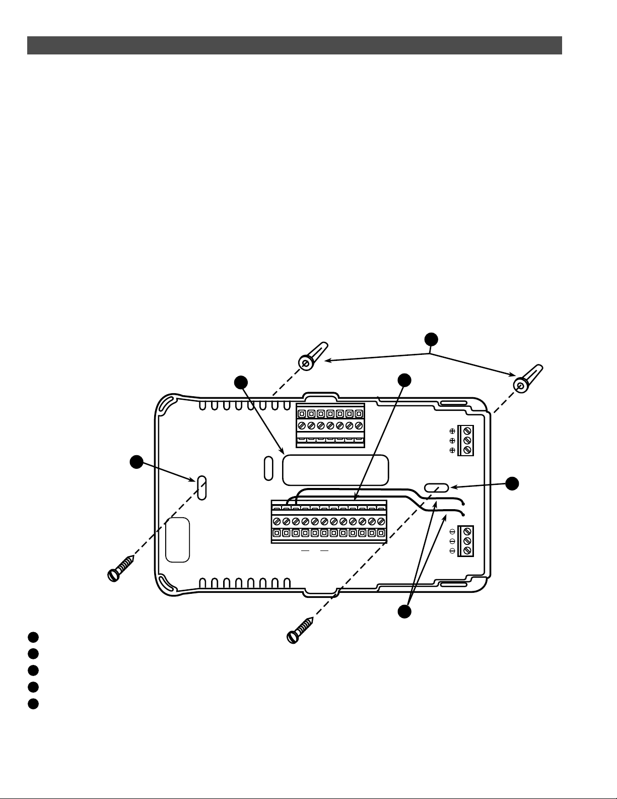
Run wires through hole in base and attach
base to wall (see fig. 1).
Insert the labeled wires into the appropriate
terminals on the base and tighten the
terminal screws.
CONFIGURING AND PROGRAMMING
Before the power is turned on, the
thermostat must be configured to operate
properly with the system. See the CONFIGURATION section of this manual.
This thermostat can be programmed for
automatic temperature control. Refer to
Operating Instructions for programming.
4
2
PH D SASBSCOTL
3
1
1
R
C
W3A1E2
RC
EW2W1Y2Y1BOG
P
5
Mounting screws
1
Pull wires through this opening
2
Insert wires into terminal holes, then tighten screws
3
Screw anchors
4
Jumper connections for remote sensor power
5
(Do not remove)
Figure 1. Thermostat base and terminals
2
HEAT PUMP TERMINAL OUTPUTS
Refer to equipment manufacturers’ instructions for specific system wiring information.
You can configure the thermostat for use
with the following heat pump system types:
HEAT PUMP TYPE 1. Single-stage
compressor system; gas or electric backup.
HEAT PUMP TYPE 2. Multi-stage or twocompressor system; gas or electric backup.
HEAT PUMP TYPE 3. System requiring
separate signals for heat (W1, W2, W3) and
cool (Y1); gas or electric backup.
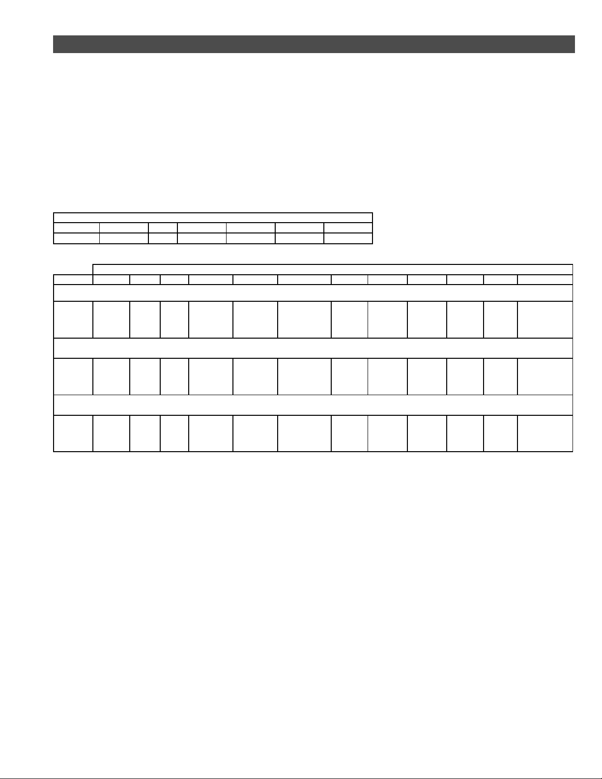
THERMOSTAT TERMINALS (Upper)
L PH D SA SB SC O T
Malfunction Light X-10 Module Input Not Used Remote Sense A Remote Sense B Remote Sense C Outdoor Sensor
SYSTEM
Single-stage compressor system; gas or electric backup
Heat Pump 1*
E C R W3/A1 W2 E2/P W1 Y2 Y1 B O G
Emergency
mode first
stage
24 Volt
(Common)
24 Volt
(Hot)
Emergency mode
3rd stage
This thermostat is designed to operate a
single-transformer system. If you have a twotransformer system, cut and tape off one
transformer. If transformer safety circuits
are in only one of the systems, remove the
transformer of the system with NO safety
circuits. If required, replace remaining
transformer with a 75VA Class II transformer.
After disconnecting one transformer, the two
commons must be jumpered together.
THERMOSTAT TERMINALS (Lower)
Heat mode 3rd
stage.
Emergency mode
2nd stage.
E2 - Emergency
mode constant
output.
P - All other modes
constant output.
Heat mode
2nd stage
No Output
Use the terminal output information below to
help you wire the thermostat properly for
your heat pump system type. After wiring,
see CONFIGURATION section for proper
thermostat configuration.
Heat and cool
modes 1st
stage
(compressor)
Energized in
Heat, Off,
Emergency
Mode
Energized in
Cool Mode
Blower/Fan Energized
on call for Heat and
Cool
Multi-stage or two compressor system; gas or electric backup
E2 - Emergency
mode constant
output.
P - All other modes
constant output.
Heat Pump 2*
Emergency
mode first
stage
24 Volt
(Common)
24 Volt
(Hot)
Emergency mode
3rd stage
Emergency mode
2nd stage.
System requiring separate signals for heat (W1, W2) and cool (Y1); gas or electric backup
Heat Pump 3**
* If system does not provide connection to E, jumper W1 to E to provide Aux heating in emergency mode.
** If system does not provide connection to E, jumper W2 to E to provide Aux heating in emergency mode.
Emergency
mode first
stage
24 Volt
(Common)
24 Volt
(Hot)
Heat mode 3rd
stage.
Emergency mode
3rd stage
Heat mode 2nd
stage.
Emergency mode
2nd stage
E2 - Emergency
mode constant
output.
P - All other modes
constant output.
Heat mode
3rd stage
Heat mode
1st stage
Heat and cool
modes 2nd
stage
(compressor 2)
No Output
Heat and cool
modes 1st
stage
(compressor 1)
Cool mode 1st
stage
Energized in
Heat, Off,
Emergency
Mode
Energized in
Heat, Off,
Emergency
Mode
Energized in
Cool Mode
Energized in
Cool Mode
Blower/Fan Energized
on call for Heat and
Cool
Blower/Fan Energized
on call for Heat and
Cool
3
 Loading...