

Page 1

ESTUFAS A GAS 30”
Instructivo de Instalación, Uso y
Cuidado
30” FS GAS RANGE
Installation, Use and Care guide
Ampara los siguientes modelos:
Covers the next models:
36
No. Parte W10289616 Rev. A stm03092 Rev. A
WF5000
WF5300
WF5400
WF5420
WF5500
WF5952
WF5910
WF5980
Page 2
35
2
Í
NDICE
Bienvenida . . . . . . . 3
Partes y características . . . . . 4
Instalación . . . . . . . 6
Conexión . . . . . . . 7
Verificación de funcionamiento . . . . 8
Ajuste de flamas . . . . . . 10
Uso de los accesorios y características . . . 12
Cuidado de la estufa . . . . . 14
Diagrama eléctrico . . . . . . 15
Póliza de Garantía . . . . . . 17
Formato de Identificación . . . . . 17
Ayuda o servicio técnico . . . . . 19
T
ABLE OF CONTENTS
Welcome . . . . . . . 20
Parts and features . . . . . . 21
Installation . . . . . . . 23
Connection . . . . . . . 24
Verify operation . . . . . . 25
Flame adjustment . . . . . . 27
Use of features and accessories . . . . 29
Range care . . . . . . . 31
Electric diagram . . . . . . 32
Warranty . . . . . . . 34
Identification format . . . . . 34
Assistance or service . . . . . 36
Page 3
34
¡Felicidades por la compra de su nueva estufa!
Acaba de adquirir un producto desarrollado con las más avanzadas técnicas
de diseño y fabricación.
Le sugerimos que antes de usar su estufa lea cuidadosamente las
instrucciones de este manual. Consérvelo, ya que la información contenida en
el mismo será importante para el buen funcionamiento de su estufa durante
muchos años.
3
Page 4

33
NOTES
P
ARTES Y CARACTERÍSTICAS
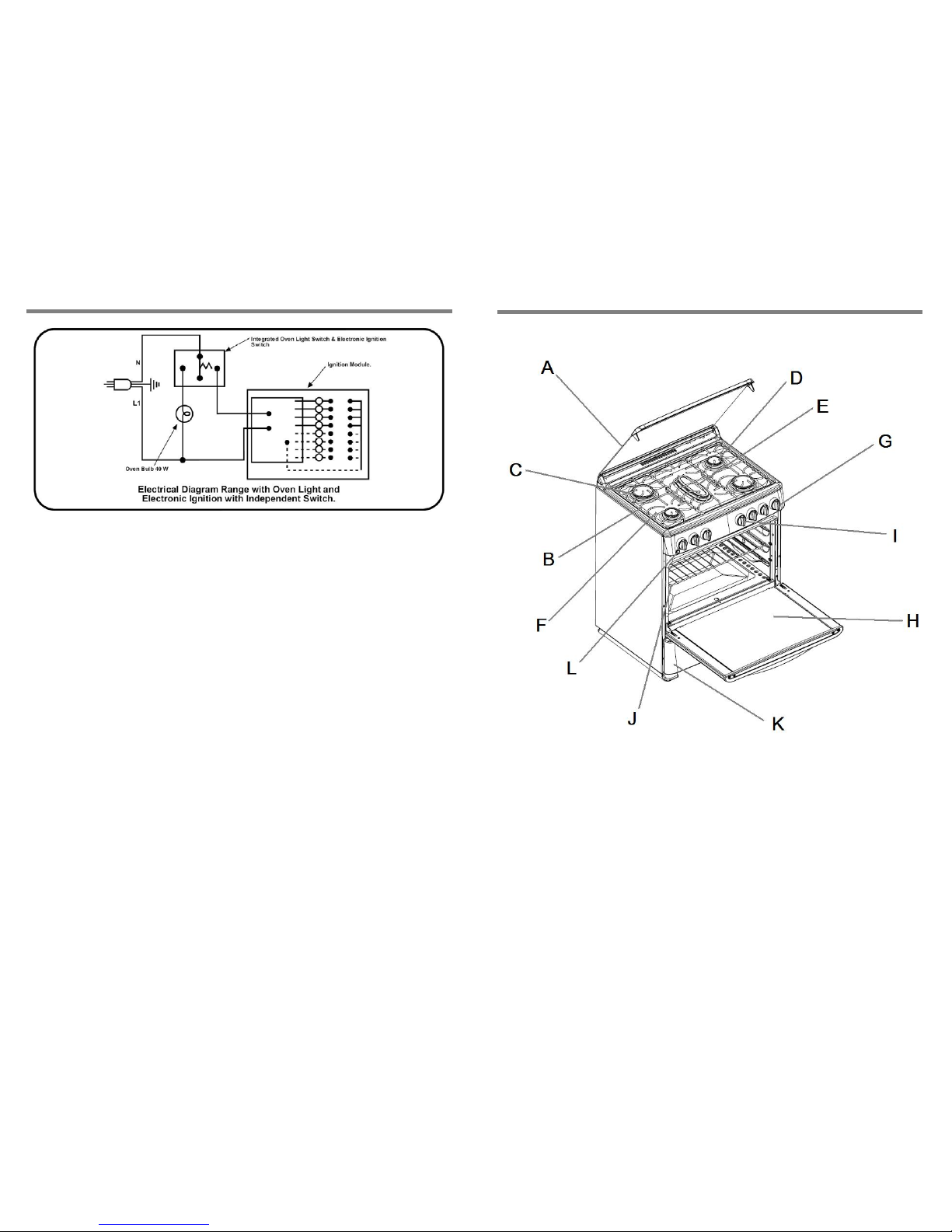
A. Respaldo
B. Parrillas superiores
C. Quemadores súper
D. Quemadores estándar
E. Quemador alargado
F. Encendido electrónico en
quemadores superiores
G. Perillas
H. Puerta de horno con
ventana extra grande
I. Termostato o termocontrol
controlado por perilla
J. Parrillas de horno
deslizables
K. Cavidad para asar
L. Luz en el horno.
4
Page 5
32
ELECTRIC DIAGRAM
PARTES Y CARACTERÍSTICAS
PRODUCT MANUFACTURED BY:
Industrias Acros Whirlpool S.A. de C.V., Unidad Celaya
Carretera Panamericana Km. 280 C.P. 38020, Celaya, Gto.
Phone: 01 (461) 6 18 55 00
A. Capelo
B. Parrillas superiores
C. Quemadores súper
D. Quemadores estándar
E. Quemador alargado
F. Encendido electrónico en
quemadores superiores
G. Perillas
H. Puerta de horno con
ventana extra grande
I. Termostato o termocontrol
controlado por perilla
J. Parrillas de horno
deslizables
K. Cavidad para asar
L. Luz en el horno
5
Page 6
Características eléctricas nominales
31
RANGE CARE
To keep the range in good performance conditions, it is needed to conduct cleaning
procedures using water, soap and a soft cloth or sponge. Do not use wire fiber as it
could permanently scratch the enamel of the range.
Before cleaning the range, make sure all knobs are off and unplug the power cord from
the electrical wall outlet. Assure the oven and cooktop are cool.
On a regular basis, clean the gap between the manifold panel and the c ooktop. The
surface grates, as well as the burners and burner caps, can be cleaned with soap and
water.
The range has the Continuous Cleaning System in the oven (rough finish inside the
oven cavity) which burns out the grease spills on the walls every time the baking
feature is used.
IMPORTANT
Do not use caustic soda or clearing agents which contain it to clean the range.
Voltaje: 127 V ~ ± 10% Frecuencia: 50/60 Hz Corriente: 1,0 A Max
Recomendaciones:
• Instale su estufa en un lugar protegido de las inclemencias del tiempo y s obre una
superficie plana y resistente para soportar su peso.
• No instale su estufa sobre alfombra o algún material inflamable. Si el piso es
sintético, verifique que éste material soporte una temperatura de al menos 95°C
sin deformarse.
• No permita que la usen niños o personas que no conozcan su funcionamiento.
• Proporciónele el mantenimiento adecuado.
• Utilice la estufa sólo en labores del hogar. No es un aparato de uso comercial.
Failure on following the above will permanently damage the surface where it is applied.
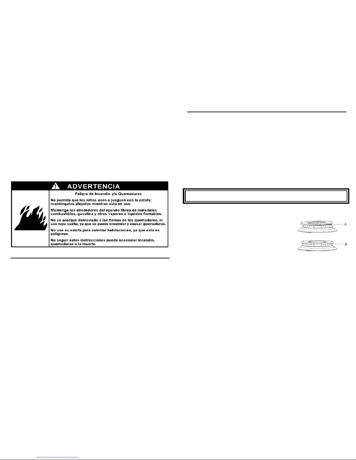
Surface burners
To keep the surface burners in food conditions, some
periodical cleaning is needed. Follow these steps to do it:
1. Remove the surface grates.
2. Take off the cap and the burner, wash them with
soapy water and rinse them thoroughly. Let them dry
completely.
3. Replace the surface burners on their orig inal position
and place the caps, making sure the alignment pins
are properly aligned with the burner cap.
INSTALACIÓN
A
. Incorrect
B. Correct
• La instalación apropiada es su responsabilidad, por lo cual es recomendable que
sea realizada por un técnico calificado o un técnico de Whirlpool Service.
• Retire todos los elementos de empaque y coloque los accesorios de la estufa.
• Seleccione la mejor ubicación para su estufa, no debe quedar expuesta a
corrientes de aire y debe tener espacio suficiente para abrir la puerta del horno.
• No instale gabinetes o muebles de cocina encima de la estufa.
• Si instala campana extractora, colóquela a 61 cm como mínimo desde la cubierta
de la estufa.
• Si su estufa cuenta con accesorios eléctricos, colóquela cerca de un
tomacorriente de pared.
• Esta estufa de gas está equipada con un enchufe de tres pu ntas con contacto a
tierra para protección contra riesgo de electrocución. Debe enchufarse
directamente a un tomacorriente debidamente aterrizado.
• No corte ni quite la punta para conexión a tierra del enchufe. No utilice
extensiones eléctricas o contactos múltiples.
Page 7
30
lass lid
ome models have a top glass lid. The glass lid is made of tempered glass and even
hen it is resistant; it should be handled with care to avoid breakings. Open and close
it without striking it, do not let it fall down before reaching its horizontal position.
before closing it and
n. Do not
e ones also have a
lled out.
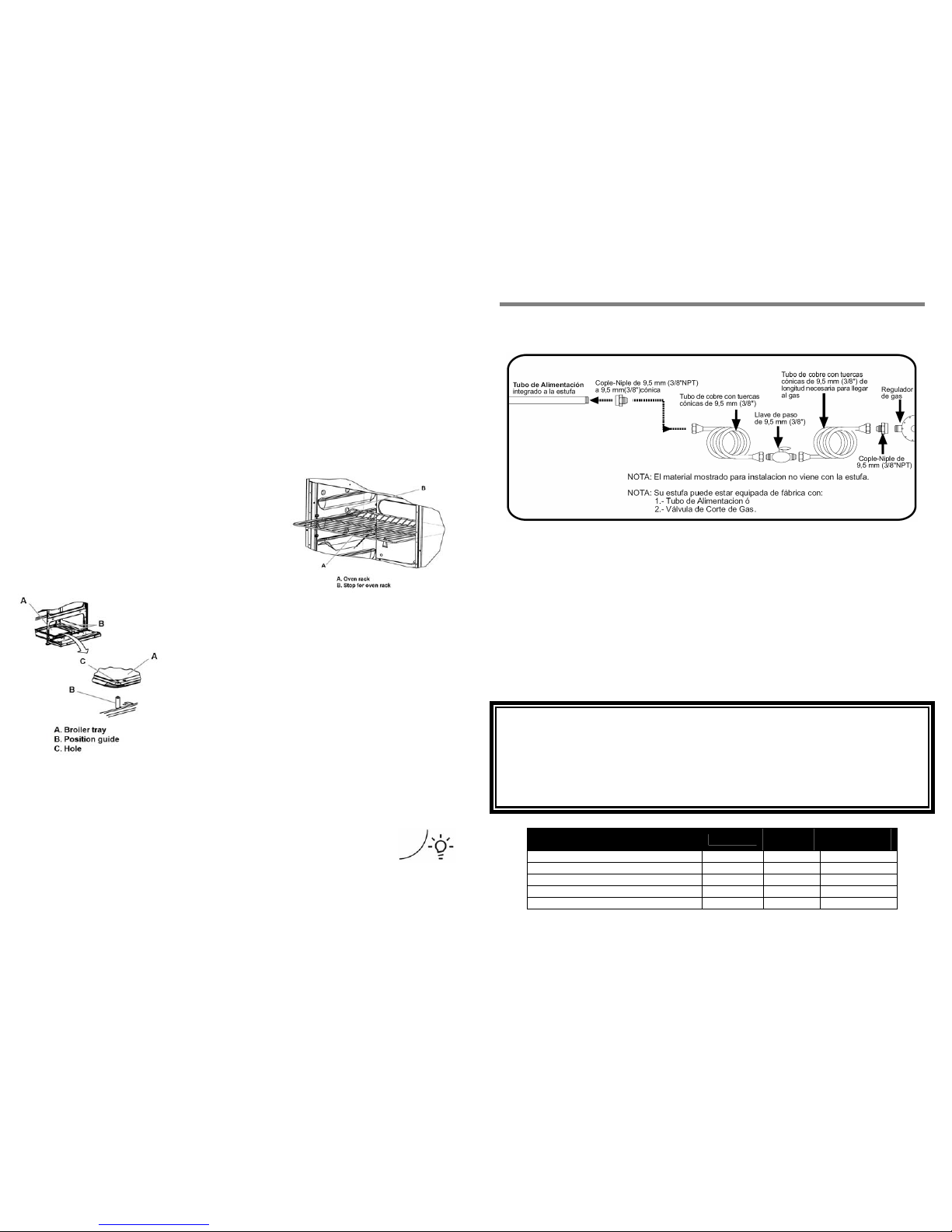
5. Place the oven rack horizontal and push it to
the stop position.
6. Raise the front edge.
7. Push again until it reaches the final position.
Broiler
The range is equipped with a broiler below the oven
door. Before using it, place the broiler tray on the 2 pins,
as shown in the pictures below. For the broil feature to
work, the oven burner should be turned on according to
the instructions for thermocontrol or thermostat.
When the oven burner is lit, turn the “Oven control”
knob to its maximum flame, which is:
- Position 5 for thermoc ontrol models
- Position 26 0°C for thermostat models
Oven light
The range has an oven light bulb, this light is important to check for baking
performance without opening the oven door.
The light inside the oven cavity turns on when the switch next to the most
left hand knob is pushed downward; it is identified with this symbol. To
turn it off, the switch needs to be pushed again.
If the bulb does not work, replace it by following this sequence:
1. Unplug the range from the electrical wall outlet.
2. Remove the bulb twisting it counterclockwise.
3. Place a new 40 Watts bulb, designed for home appliances.
4. Plug the power cord of the range into the electrical wall outlet.
G
S
w
Assure that the surface burners are all turned off and cooled down
never turn on the surface burners when the glass lid is dow
place hot cookware on top of the glass lid.
Oven racks
The oven cavity has 3 different heights for the racks position; thes
stop position to avoid them from falling down of the range when pu
To change the oven rack position, follow the next steps:
1. Pull the oven rack out to the stop position.
2. Raise the front edge.
3. Lift it out to release it.
4. Select the new height.
CONEXIÓN
Conexión de la estufa a la línea de gas
1. Para conectar su estufa utilice el material especificado en la figura de abajo:
2. Verifique que no existan fugas vertiendo espuma de jabón en las conexiones y
curvas de los tubos.
Recomendaciones:
• Si la instalación no es nueva, limpie los tubos para evitar que se tapen las
espreas o los pilotos.
• Con el fin de facilitar el movimient o del aparato, el instalador debe hacer una
espiral con el tubo flexible de cobre e instalar una llave de paso en la línea de
suministro de gas. Esta llave debe estar fuera de la estufa y accesible a las
personas que la usan.
IMPORTANTE
• Esta estufa está preparada para funcionar con gas LP de tanque móvil o
estacionario.
• Para usarse con gas Natural (tubería) debe llamar a Whirlpool Service para
cambiar las espreas y hacer los ajustes necesarios. El número telefónic o aparece
en la página 19. El técnico calificado debe cerciorarse que la cone xión no tiene
fugas y que la presión de gas en la estufa es la que aparece en las tablas
siguientes:
GAS LP PRESIÓN DE OPERACIÓN
2,75 kPa (28 cm Col. agua)
ESPREA
DIAM
ESPREA
CAPACIDAD
TÉRMICA
QUEMADOR NÚMERO mm kJ/h
SUPERIOR ESTÁNDAR ALUMINIO 78 0,78 7 000
SUPERIOR SÚPER ALUMINIO 86 0,86 7 500
SUPERIOR CENTRAL ALUMINIO 80 0,80 7 900
HORNO 57 1,092 13 600
7
Page 8
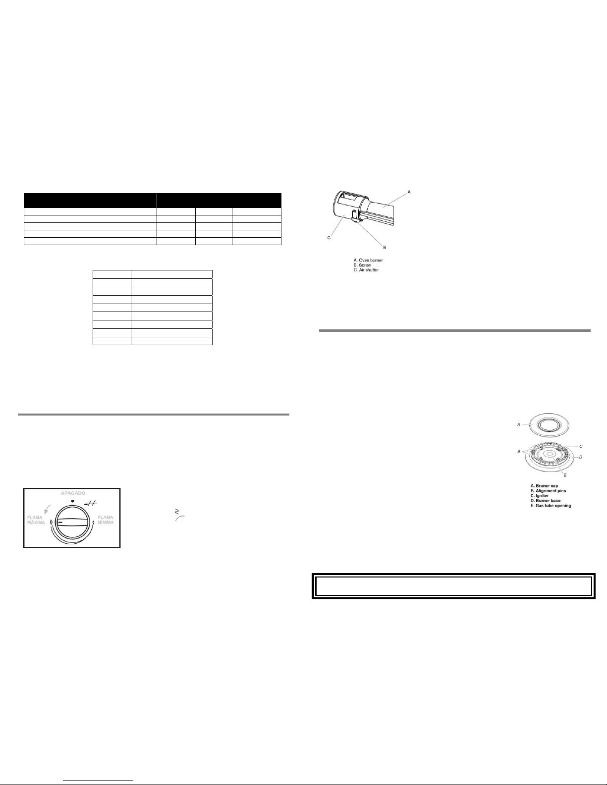
GAS NATURAL PRESIÓN DE OPERACIÓN
1,76 kPa (18 cm Col. agua)
ESPREA
DIAM
ESPREA
CAPACIDAD
TÉRMICA
QUEMADOR NÚMERO mm kJ/h
SUPERIOR ESTÁNDAR ALUMINIO 115 1,15 7 000
SUPERIOR SÚPER ALUMINIO 118 1,18 7 500
SUPERIOR CENTRAL ALUMINIO 118 1,18 7 900
HORNO 52 1,613 13 600
29
and washer, tight them
xed.
8. Turn the oven burner back on according to the
sequence on “Verify operation”, “Oven burner”
section. If the flame is now stable and blue,
the range is ready to be used; otherwise, wait
for the burner to cool down and repeat from
step 3.
9. When the oven burner has been adjusted and
is placed inside the oven cavity, replace the
oven tray and fix again the two front brackets
on its original position. Continue with the
verification of the oven burner function.
OTE: Do not obstruct the heat and air flow on the oven cavity; avoid covering the
ven tray grooves if aluminum foil is used.
SE OF FEATURES AND ACCESSORIES
riddle
mong the accessories of the range, you will find a griddle, which can be placed either
n top of the center burner or on top of any of the both side burners.
OTE: Use the griddle only with LOW FLAME.
o not use abrasive materials, plastic fibers or wire fibers to clean the griddle, use
oap and a soft sponge.
urface burners
urner cap
lways keep the burner cap in place when using a surface
urner. A clean burner cap will help avoid poor ignition and
neven flames. Always clean the burner cap after a spillover
nd routinely remove and clean the caps and bases
ccording to the “Range care”, “Surface burners” section.
as tube opening
as must flow freely throughout the gas tube opening for the
urner to light properly. Keep this area free of soil and do not
llow spills, food, cleaning agents or any other material to
nter the gas tube opening. Protect it from spillovers by always using the burner cap.
urner ports
good flame is blue in color, not yellow. Keep this ar ea free of soil and do not allow
pills, food, cleaning agents or any other material to enter the burner ports.
MPORTANT
o not obstruct the flow of combustion and ventilation air around the burner grate
7. Replace the fastener
until the oven burner is fi
NOTA: Para operar esta estufa con gas natural, se requiere el juego de convers ión de
acuerdo con la siguiente tabla y puede solicitarlo en su Centro de Servicio Autorizado:
Modelo Gas LP a gas Natural
WF5000 W10238244
WF5300 W10238244
WF5400 W10238246
WF5420 W10239488
WF5500 W10238244
WF5952 W10238246
WF5910 W10238246
WF5980 W10239488
N
o
U
G
A
Conexión de la estufa a la corriente eléctrica
o
Terminada la conexión a la línea de gas, conecte la estufa a la corriente eléctrica.
N
El cable tomacorriente debe conectarse a una toma de corriente con un voltaje de 127
V ~ ± 10%. Cerciórese de que la instalación está apropiadamente aterrizada.
D
s
VERIFICACIÓN DE FUNCIONAMIENTO
S
Ya que la estufa fue instalada es necesario verificar que la conexión de gas y eléctrica
hayan sido realizadas con éxito. Para esta actividad, coloque la estufa en su posición
final y proceda a iniciar el funcionamiento de los quemadores superiores y del horno.
Quemadores superiores
Su estufa cuenta con encendido electrónico de dos pasos para los quemadores superiores.
Para corroborar el funcionamiento siga estos pasos:
1. Presione ligeramente hacia arriba, y mantenga
así, el interruptor localizado junto a la perilla de
extrema izquierda identificado con este
símbolo
, presione y gire cualquiera de las
cinco perillas de quemadores superiores hasta
la posición de flama máxima (ver figura).
Escuchará el sonido de la chispa de la bujía y
se encenderá la flama, proceda al paso 6. Si la
flama no enciende o la chispa no se oye, realice los pasos 2 al 5.
2. Retorne la perilla a la posición de apagado y suelte el interruptor.
3. Cuando la chispa no se genere, asegúrese de haber conectado el cable
tomacorriente, sin él, el interruptor y las bujías no pueden trabajar.
4. Verifique que haya suministro de gas, ya sea en el tanque o en la línea. También
revise las conexiones y tubos, podrían estar doblados o bloqueados.
B
A
b
u
a
a
G
G
b
a
e
B
A
s
I
D
edges.
8
Page 9
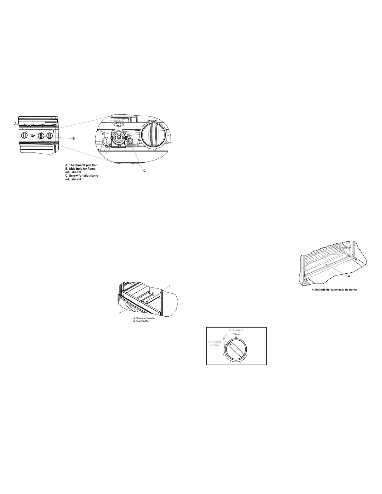
5. Habiendo corroborado las conexiones eléctricas y de gas, presione nuevamente el
interruptor y gire la perilla a la posición de flama máxima, el quemador deberá
encenderse.
6. En cuanto la flama encienda, libere el interruptor. Esta misma secuencia puede
realizarla para los otros quemadores superiores.
7. Terminada la verificación, apague todos los quemadores.
Aún con una interrupción de energía eléctrica, los quemadores superiores pueden
funcionar. Cuando esto suceda, realice lo siguiente:
1. Acerque un cerillo encendido al quemador que desea encender.
2. Gire la perilla de dicho quemador hasta la posición de flama máxima, la flama
deberá encenderse.
6. Through the small hole on the side, locate the adjusting screw for the pilot
flame. With a thin flat screwdriver twist it until the flame is ½” high.
7. When the flame has reached the proper height, place the knob’s base and
spring and finish with the knob itself. Turn it to the off position.
8. Replace the oven tray and fix again the two front brackets on its original
position.
9. Turn the oven burner again and continue with the function verification.
ven burner flame
ometimes, the different altitudes over the sea level and variations on the supply gas
ressure, results in the need of adjusti der to obtain an
ptimum performance of the oven when is used. The surface burners do not need this
djustment.
hen the oven burner flame is yellow or unstable, follow the next steps to improve
ese conditions:
. Turn off all the knobs and let the range cool down completely.
. Remove the oven tray by releasing the
both front fixing brackets and lift it by the
front edge. Pull it towards yourself and take
it out of the oven cavity (see picture on
left).
. Locate the screw that supports the oven
burner to the front frame (see picture on
left) and with a screwdriver release the
fastener and store it with the washer on a
safe place.
er and remove it from the oven cavity.
. To adjust the air-gas mixture, release the screw of the air shutter and twist it to
open or close the window (see picture on next page). If the flame is yellow, the
window in the air shutter must be opened. When the flame is unstable or
separates from the oven burner, the window in the air shutter must be reduced.
. After adjusting the window size in the air shutter, tight the screw and place the
oven burner back in the oven cavity.
3. Regule la flama a la potencia deseada.
Quemador de horno
Dependiendo del modelo, su estufa cuenta con un quemador de horno controlado por un
termocontrol de 5 pasos o por un termostato con encendido manual. Si es un termocontrol,
la perilla titulada “Oven Control” deberá estar rodeada de los números 5 al 1.
Si la estufa tiene termostato, la perilla deberá estar rodeada de temperaturas que van desde
140 °C hasta 260 °C. Para corroborar el correcto funcionamiento, siga los siguientes pasos
dependiendo del modelo de su estufa.
O
Modelos con termocontrol de 5 pasos
S
p ng the air-gas mixture in or
1. Abra la puerta del horno.
o
2. Encienda un cerillo y acérquelo a la
entrada del quemador de horno
mostrada en la figura.
a
W
th
3. Presione y gire la perilla nombrada
“Oven Control” a su posición inicial
(posición 5).
1
2
4. La flama deberá encenderse y
empezará a generar calor. Continúe al
paso 7. Si la flama no enciende, realice
los pasos 5 y 6.
3
4. Hold the oven burn
5
6
5. Cuando la flama no enciende, retorne la perilla a la posición de apagado y
verifique que haya suministro de gas, ya sea en el tanque o en la línea.
También revise las conexiones y tubos, podrían estar doblados o bloqueados.
6. Habiendo hecho esto, intente encender nuevamente el quemador con a yuda de
otro cerillo. Si tuvo éxito, continúe al paso 7, de lo contrario, retorne al paso 5.
7. Cierre la puerta de horno y abra la puerta
del asador. Observe la flama, normalmente
debe ser azulada y estable; si no es así,
proceda a la sección de “Ajuste de flamas”,
“Flama del quemador de horno”.
8. Habiendo verificado el quemador de horno
y ajustado la flama, gire la perilla a la
posición de apagado. Su estufa ha
quedado lista para utilizarse.
9
28
Page 10
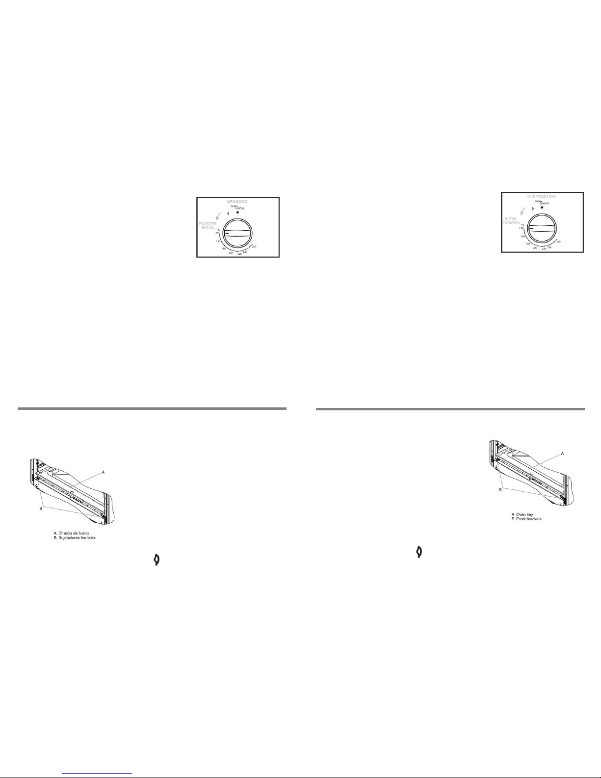
Modelos con termostato de encendido manual
27
stat
If the flame does not lit, return the knob to the off position and verify that gas
w match. If you succeed continue to step 7, otherwise return to step 5.
e oven door and open the broiler door. On the rear part of the oven
e pilot flame can be seen, this flame should be ½” high. To adjus t the
height of the pilot flame, review the section “Flame adjustment”, “Oven pilot
way, proceed to the “Flame adjustment”, “Oven burner flame” section.
9. After verifying the oven burner function and having adjusted the flame, turn the
f position.
l, the range is ready to be
O
mi
fla
Verify the range is completely cool and the
knobs are in the off position.
Remove the oven bottom by releasing the
both front fixing brackets and lifting the oven
tray by the front edge. Pull it towards yourself
and take it out of the oven cavity (see picture
on right).
Light the oven burner as explained on the
“Oven burner”, “Models with thermostat”
section.
Turn the “Oven control” knob” clockwise until it reaches the pilot position,
identified by this symbol
Models with thermo
1. Abra la puerta del horno.
2. Encienda un cerillo y acérquelo a la entrada del
quemador de horno (ver figura página anterior).
3. Presione y gire la perilla nombrada “Oven Control” a
su posición inicial (posición 140°C).
4. La flama deberá encenderse y empezará a generar
calor. Continúe al paso 7. Si la flama no enciende,
realice los pasos 5 y 6.
5. Cuando la flama no enciende, retorne la perilla a la
posición de apagado y verifique que haya suministro de gas, ya sea en el tanque o
en la línea. También revise las conexiones y tubos, podrían estar doblados o
bloqueados.
6. Habiendo hecho esto, intente encender nuevamente el quemador con ayuda de otro
cerillo. Si tuvo éxito, continúe al paso 7, de lo contrario, retorne al paso 5.
7. Cierre la puerta de horno y abra la puerta del asador. Observe la flama, en la parte
posterior se distingue la flama del piloto del quemador, esta deberá tener
aproximadamente 1 cm de altura. Para ajustar la altura de la flama, revise la sección
“Ajuste de flamas”, “Flama del piloto del quemador de horno”.
8. La flama del quemador deberá cubrir todos los orificios y normalmente debe ser
azulada y estable; si no es así, proceda a la sección de “Ajuste de flamas”, “Flama
del quemador de horno”.
9. Habiendo verificado el quemador de horno y ajustado las flamas, gire la perilla a la
posición de apagado.
Cuando termine de realizar estas operaciones y los resultados sean exitosos, podrá utilizar
su estufa de manera cotidiana.
AJUSTE DE FLAMAS
Flama del piloto del quemador de horno
Cuando se enciende por primera vez el quemador de horno, puede ser necesario
ajustar la altura de la flama del piloto. Siga estos pasos para realizar dicha operación:
1. Verifique que la estufa esté completament e
fría y todas las perillas en la posición de
apagado.
2. Retire la charola del piso de horno gira ndo
los dos sujetadores frontales y levantando la
charola por el frente. Jale hacia usted y
retírela de la estufa (ver figura izquierda).
3. Encienda el quemador de horno tal y como
se explica en la sección “Quemador de
horno”, “Modelos con termostato de
encendido manual”.
4. Gire la perilla “Oven Control” en sentido de
las manecillas del reloj hasta la posición de
piloto, identificada con este símbolo
. El quemador de apagará pero la flama
del piloto permanecerá encendida.
5. Retire la perilla de “Oven Control” junto con su base y resorte, guárdelos en un
lugar seguro.
1. Open the oven door.
2. Light a match and approach it to the oven burner
tube (see picture on previous page).
3. Push an d turn the “Oven control” knob to its initial
position (140°C).
4. The flame should light and the cavity should begin
heating. Proceed to step 7. If the flame does not
appear, continue with steps 5 and 6.
5.
supply is available, either on the tank or in the line. Also, check the pipe line and
connections, as they could be twisted or blocked.
6. After checking connections and gas supp ly, try to light the oven burner again
with a ne
7. Close th
burner th
flame”.
8. The normal flame on the oven burner should be blue and stable; if it is not this
knob to the of
When these verifications have been done and successfu
used.
FLAME ADJUSTMENT
ven pilot flame
When the oven burner is lighted the first time, it
ght be necessarily to adjust the height of the pilot
me. Follow these steps to adjust it:
1.
2.
3.
4.
. The oven burner will turn off but the pilot flame will
remain lit.
Remove the “Oven control” knob togeth er with the base and the spring, store
them in a secure place.
5.
10
Page 11
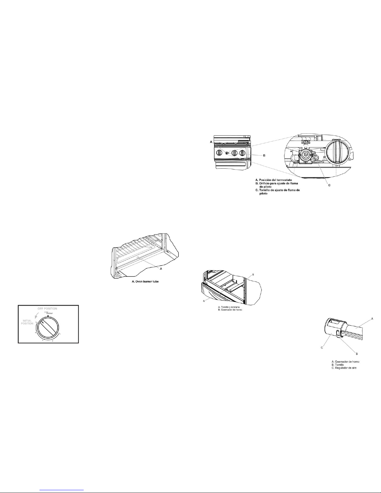
6. A través del orificio pequeño, localice el tornillo de ajuste de la flama del piloto
en el termostato y con un desarmador plano y delgado gírelo hasta obtene r una
flama de aproximadamente 1cm de alto.
4. Verify that gas supply is available, either on the tank or in the line. Also, check the
pipe line and connections, as they could be twisted or blocked.
5. Having checked the electrical and gas connections proceed to press again the
switch and turn the knob to the maximum flame position; the burner should lit.
6. As soon as the flame covers the burner, release the switch. This same sequence
can be followed to verify the function of the other surface burners.
7. Alter all the burners have been lighted, turn them off.
Even used. If this happens,
ructions to operate your range:
en
pen odel, the oven burner can be controlled by a 5 steps
at that lights manually. If the range has a thermocontrol, the
surrounded by the numbers 5 through 1.
he r nded by temperatures that begin on
°C To verify the oven burner function, follow the next steps,
en
Models with a 5 steps therm
1. Open the oven door.
2. Light a match and appr
burner tube (see picture
3. Push and turn the “Ove
its initial position (numb
h
should begin heatin 7.
If the flame does not
with steps 5 and 6.
5. If the flame does not lit, ret n t y that gas
supply is available, either on the tank or e line and
connections, as they could b w
6. d gas
supply, try to light the oven burner again
with a new match. If you succeed continue
to step 7, otherwise return to step 5.
should be blue and stable; if it is not this
djustment”,
nd having adjusted the flame, turn the
when an electrical failure occurs, the surface burners can be
follow these inst
1. Light a match and approach it to the burner that you wish to use.
2. Turn the knob of the burner to the maximum flame position.
3. Regulate the flame to the desired intensity for use.
Ov burner
De ding on the range’s m
thermocontrol or by a thermost
7. Cuando la flama está a la altura deseada, coloque la base de la perilla, el
resorte y la perilla. Gírela a la posición de apagado.
knob titled “Oven control” must be
8. Coloque la charola del piso de horno y regrese los dos sujetadores frontales a
su posición original.
If t ange has a thermostat, the knob should be surrou
140 and end up in 260°C.
9. Encie nda nuevamente el quemador de horno y continúe con la verificación de
funcionamiento.
dep ding on the model of the range:
ocontrol
Flama del quemador de horno
Las diferentes altitudes sobre el nivel del mar y las variaci on es e n el suministro de gas,
hacen necesario regular la entrada de aire primario del quemador de horno para
obtener una adecuada mezcla de aire-gas y obtener un buen funcionam iento cuando
se utiliza. Los quemadores superiores se excluyen de esta regulación.
Cuando la flama de
oach it to the oven
).
n control” knob to
er 5).
t and the cavity
g. Proceed to step
4. The flame should lig
l quemador de horno no es
stufa esté completamente
retírela de la estufa (ver figura en pa
3.
4.
egulador
azulada y estable, siga esta secuencia para
mejorar ésta condición:
1. Verifique que la e
appear, continue
ur he knob to the off position and verif
in the line. Also, check the pip
fría y todas las perillas apagadas.
2. Retire l a charola del piso de horno girando
e t isted or blocked.
After checking connections an
los dos sujetadores frontales y levantando
la charola por el frente. Jale hacia usted y
gina anterior).
Localice el tornillo que sujeta el quemador al
7. Close the oven door and op en the broiler
door. You can observe the flame, and it
way, proceed to the “Flame a
“Oven burner flame” section.
8. After verifying the oven burner function a
knob to the off position. The range is ready for operation.
bastidor frontal de la estufa y con ayuda de un
desarmador, desatornille y guarde el tornillo junto
con la rondana.
Sujete el quemador y retírelo de la estufa.
5. Para ajustar el aire afloje el tornillo del r
de aire y gire para abrir o cerrar la ventana (ver
figura derecha). Si la flama estaba amarilla es
necesario abrir la ventana. Cuando la flama es
inestable o se separa del quemador, es necesario
cerrar ligeramente la ventana.
26
11
Page 12
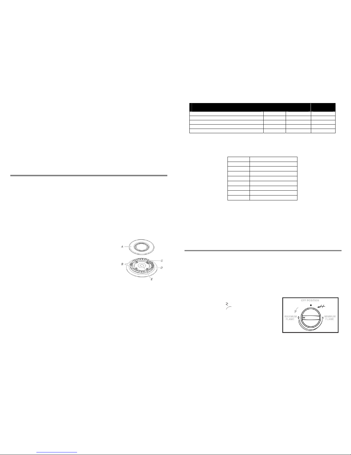
6. Cuando termine de ajustar la ventana, apriete el tornillo del regulador y coloqu e
nuevamente el quemador dentro de la estufa.
7. Coloque el tornillo con la rondana y apriete para sujetar el quema dor.
8. Encienda nuevamente el quemador de acuerdo a la secuencia en “Verificación
de funcionamiento”, “Quemador de horno”. Si la flama ya está estable y
azulada, la estufa ha quedado lista para operación; de lo contrario espere a que
el quemador se enfríe y retorne al paso 3.
9. Cuando el quemador d e horno ha sido ajustado y está colocado dentro de la
estufa, retorne charola del piso y gire los sujetadores a su posici ón original.
Continúe con la verificación de funcionamiento del quemador de horno.
NOTA: No obstruya la salida de aire del horno, no cubra los orificios de l a charola de
horno.
USO DE LOS ACCESORIOS Y CARACTERÍSTICAS
Comal
Dentro de los accesorios de su estufa, usted encontrará el comal, el cual puede
colocar sobre el quemador central o sobre cualquiera de los dos pares de quemad ores
laterales.
NOTA: Use el comal con FLAMA BAJA.
No use materiales abrasivos, fibras de plástico o metal para limpiarlo, utilice agua
jabonosa y una esponja.
Quemadores superiores
Tapa del quemador
Cuando use los quemadores exteriores mantenga siempre
la tapa del quemador en su lugar. La tapa limpia del
quemador ayudará a prevenir el encendido inadecuado y
las llamas desiguales. Siempre limpie la tapa del
quemador después de un derrame y como rutina quite y
limpie las tapas y bases tal como lo indica la sección
“Cuidado de la estufa”, “Quemadores superiores”.
Abertura del tubo de gas
El gas debe fluir con libertad a través de la abertura del
tubo de gas para que el quemador se encienda
adecuadamente. Mantenga esta zona libre de suciedad y
no permita el ingreso de derrames, alimentos, productos de
limpieza o cualquier otro material. Para protegerla de los
derrames, siempre use la tapa del quemador.
Orificios del quemador
Una buena llama es de color azul, no amarillo. Mantenga los orificios libres de
suciedad y no permita el ingreso de derrames, alimentos, productos de limpieza o
cualquier otro material.
A
. Tapa del quemado
r
B. Espigas de alineación
C. Bujía
D. Base del quemador
E. Abertura del tubo de gas
25
NATURAL GAS OPERATING PRESSURE
ORIFICE
ORIFICE
DIAMETER
THERMAL
CAPACITY 1,76 kPa (18 cm water column)
BURNER NUMBER mm kJ/h
SURFACE STANDARD ALUMINUM 115 1,15 7 000
SURFACE SUPER ALUMINUM 118 1,18 7 500
SURFACE FISH ALUMINUM 118 1,18 7 900
OVEN 52 1,613 13 600
NOTE: To replace the orifices in the rang
request it to the closest Au ed
according to this table:
Model L
e, a conversion kit is required and you can
thoriz Service Center. Verify your range’s model
P gas to Natural gas
WF5000 W10238244
WF5300 W10238244
WF5400 W10238246
WF5420 W10239488
WF5500 W102382 4 4
WF5952 W10238246
WF5910 W10238246
WF5980 W10239488
Electrical connection
After finishing the gas supply connection, plug the range to the electrical wall outlet.
The power cord must be connecter to an electrical line with voltage 127 V ~ ± 10%.
Verify that this installation is properly grounded.
PERATION
ssful gas an electrical
ange to its final position
ation.
o steps electronic ignition system for the surface burners. To assure they
symbol
VERIFY O
Once the range has been installed, a verification of succe
connections should be conducted. For this activity, move the r
and proceed to verify the surface burners and oven burner oper
Surface burners
The range has a tw
are properly working, follow these steps:
1. Slightly press upward and maintain the switch
located aside the most left hand knob, identified
with this
. Push and turn any of the
five surface burner knobs to the maximum flame
to step 6. If the flame does not lights or
r does not sparks, proceed to follow
steps 2 to 5.
electrical wall outlet, if it is unplugged neither the switch nor the igniters will work.
position (see figure on right). You will hear the
igniter sparking and the flame should be lit,
proceed
the ignite
2. Return the knob to its off position and release the switch.
3. If the spark is not being generated, assure the power cord is connected to the
12
Page 13
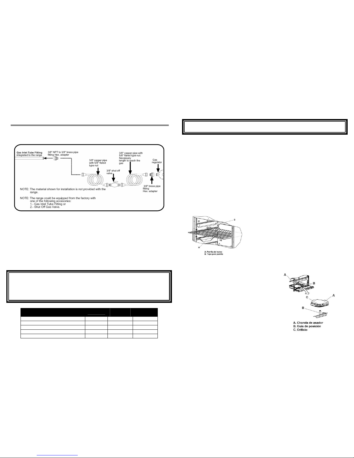
C
ONNECTION
Gas supply connection
1. To connect the range, use the material shown in the figure below:
IMPORTANTE
No obstruya el flujo de aire de combustión y de ventilación alrededor de los bordes d e
la parrilla del quemador.
Capelo de vidrio
Algunos modelos cuentan con capelo de vidrio. El capelo es de vidrio templado y
aunque es resistente debe manejarse con cuidado para evitar que s e rompa. Abra y
cierre el capelo sin golpearlo, no lo deje caer antes de que llegue a su posición
horizontal.
Asegúrese que los quemadores estén apagados cuando cierre el capelo y
nunca
encienda los quemadores cuando el capelo se encuentre abajo. No
coloque recipientes calientes sobre el capelo.
Parrillas del horno
El horno tiene 3 diferentes posiciones de elevación para las parillas interiores; éstas
tienen un tope que evita se salgan completamente cua ndo son movidas hacia fuera.
Para cambiar la posición de la parrilla, siga los siguientes pasos:
y no leaks are present in the line.
of the orifice spuds and/or pilots.
all a shut off valve on the line. This valve must be outside the range
IMPO
• T
1. Jale la parrilla hasta el tope.
2. Use soap solution to verif
2. Levante la parrilla de la parte frontal.
3. Jale nuevamente para liberarla.
Recommendations:
• If your gas installation is not new, clean the pipes and connections in order to av oid
obstruction
4. Seleccione la altura a la cual desea
cambiarla.
5. Empuje la parrilla hasta el tope.
6. Levante la parrilla de la parte frontal.
• For an eas y and close movement of the range, the installer should loop the copper
tubing and inst
7. Empújela nuevamente para que llegue hast a
el fondo del horno.
and accessible for the user.
Asador
RTANT
he range is set up from factory for LP gas use.
Su estufa cuenta con asador en la parte inferior
de la estufa. Antes de utilizarlo coloque la
charola en las 2 guías tal como se muestra en
las figuras.
• o use the range with Natural gas, the orifiT st be replaced by a ce spuds mu
W ber can be found on page 36. The hirlpool Service technician. The phone num
Para que el asador funcione debe encender el
quemador de horno de acuerdo a las
instrucciones para termocontrol o termostato.
te ections have no leaks and the gas chnician must assure that the line and conn
p the charts: ressure in the range is the same as shown in
LP GAS OPERATION PRESSURE
2,75 kPa (28 cm water column)
ORIFICE
ORIFICE
DIAMETER
THERMAL
CAPACITY
BURNER NUMBER mm kJ/h
SURFACE STANDARD ALUMINUM 78 0,78 7 000
Cuando esté encendido el quemador, gire la
perilla “Oven control” a su flama máxima, la cual
es:
- Posición 5 para modelos con
termocontrol
SURFACE SUPER ALUMINUM 86 0,86 7 500
SURFACE FISH ALUMINUM 80 0,80 7 900
OVEN 57 1,092 13 600
- Posición 260°C para modelos con
termostato.
13
24
Page 14
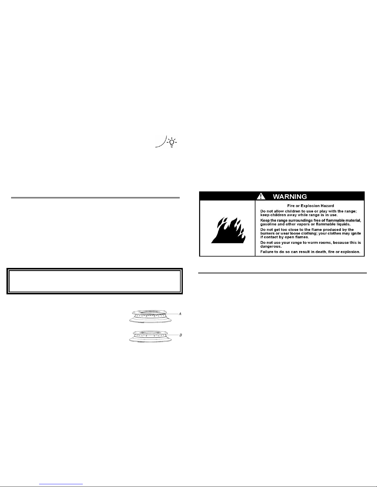
Luz de horno
23
lectrical requirements
10% Frequency: 50/60 Hz Current: 1,0 A Max
Recomme
In eather exposure, on a level
fl
D ered with any flammable
m material can withstand more
th
• D en or unqualified adults.
P
• U
c
E
Su estufa cuenta con luz en el horno, esta iluminación es importante para revisar el
horneado sin necesidad de abrir la puerta.
Voltage: 127 V ~ ±
ndations:
La luz de horno se enciende cuando se presiona hacia abajo el
interruptor que se localiza junto a la perilla de extrem a izquierda y que
tiene el símbolo mostrado a la derecha. Para apagar la luz, presione
nuevamente el interruptor.
• stall your range in an area that is protected against w
oor strong enough to sustain its weight.
• o not install the range ov er carpeted floor or floor cov
aterial. If the floor has a synthetic cover, verify this
an 95°C without deforming.
o not allow range to be used by childr
Cuando el foco interior deje de funcionar, reemplácelo siguiendo estos pasos:
1. Desconecte el cable tomacorriente de la estufa.
2. Retire el foco girándolo en contra de las manecillas del reloj.
• rovide adequate maintenance.
se this range only for household applications. It was not designed for
3. Coloque un nuevo foco de 40 Watts especial para aparatos electrodomésticos.
4. Conecte la estufa a la toma de corriente.
ommercial use.
CUIDADO DE LA ESTUFA
Para mantener su estufa en buenas condiciones de funcionamiento, es necesario
realizarle limpieza periódica utilizando agua, jabón y un trapo húmedo. No utilice fibra
metálica ya que puede rayar y dañar permanentemente el esmalte.
Antes de iniciar la limpieza, desconecte el cable tomacorrient e y asegúrese que la
estufa esté completamente fría. Limpie regularmente el espacio entre la cubierta
superior y el frente de perillas, las parrillas superiores, tapas y quemadores pueden
lavarse con agua y jabón.
El horno tiene el Sistema de Autolimpieza (acabado rugoso), el cuál va quemando
los residuos de alimentos que se salpican durante el uso, por lo cual no es necesario
que limpie las paredes o el piso.
ualified technician or Whirlpool
e range.
R he range accessories on their
p
S kitchen, it should not be exposed
to door.
• D
If t least 61 cm above the range
c
If
• This range is equipped with a three-prong grounding plug for your protection
a s
re
Do not cut or remove the grounding prong from this plug. Do not use ext ension
c
IMPORTANTE
INSTALLATION
No utilice sosa cáustica o productos de limpieza que la contengan para limpiar la
estufa.
• Proper installation is your responsibility. A q
Service technician must install th
De no seguir esta instrucción se ocasionarán daños permanentes en las superficie s
donde se aplique.
• emove all packaging materials and place t
osition.
Quemadores superiores
• elect the best location for the range within your
wind and have enough space to open the oven
o not install cabinets directly above the range.
Para mantener en buen estado los quemadores de su
estufa, es necesario realizarles limpieza periódica o cada
vez que haya un derrame. Realice los siguientes pasos:
1. Quite las parrillas superiores.
2. Retire la tapa, el quemador y lave con agua jabonosa
y una esponja. Enjuague perfectamente y seque.
3. Cuando los quemadores estén secos, coloque
nuevamente cada uno en su posición correspondiente
junto con su tapa, asegurándose de alinearla con las
espigas de alineamiento.
A
. Incorrecto
B. Correcto
• you wish to install a range hood, place it a
ooktop.
• your range has a power cord, install it near an electrical wall outlet.
gainst shock hazard and hould be plugged directly into a properly grounded
ceptacle.
•
ords or multiple outlet devices.
14
Page 15
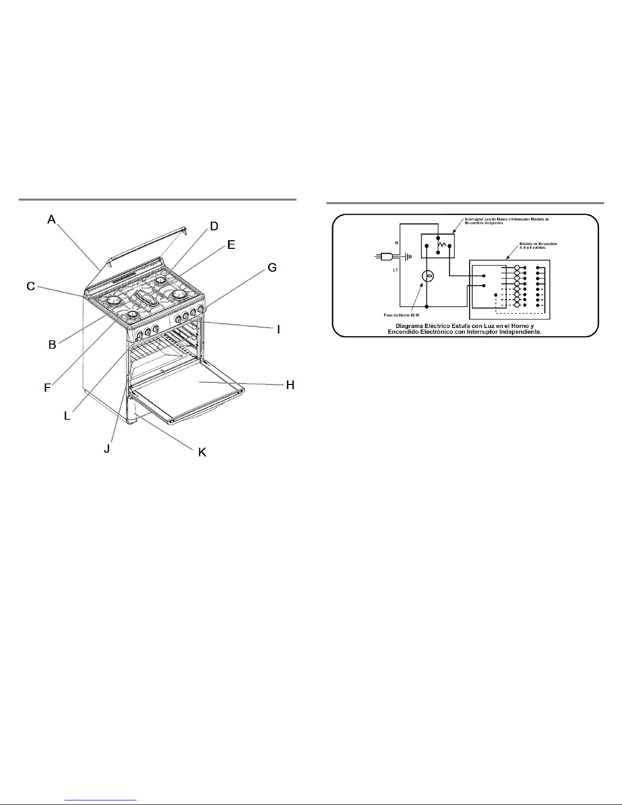
DIAGRAMA ELÉCTRICO
PARTS AND FEATURES
PRODUCTO FABRICADO POR:
Industrias Acros Whirlpool S.A. de C.V., Unidad Celaya
Carretera Panamericana Km. 280 C.P. 38020, Celaya, Gto.
G
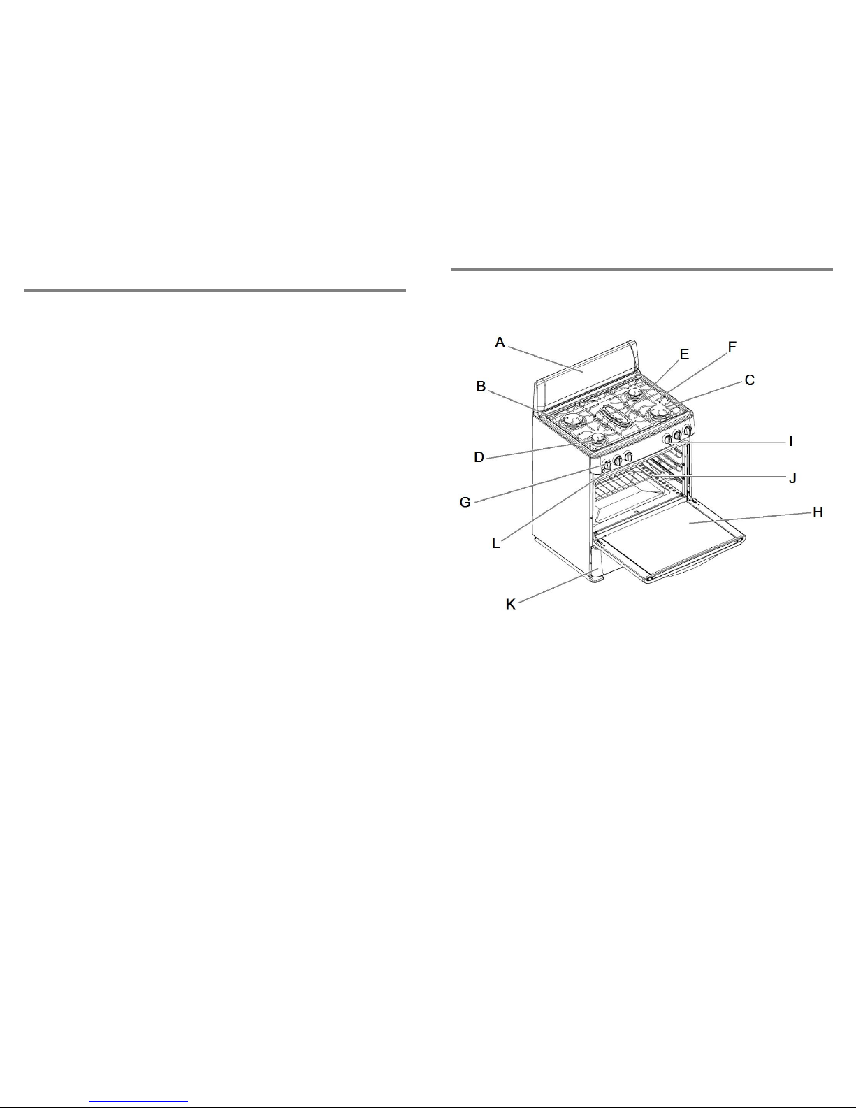
B. S
D. Standard burners
E. Fish burner
F. Electronic ignition for
surface burners
G. Knobs
Tel. 01 (461) 6 18 55 00
A. lass lid
urface grates
C. Super burners
H. Oven door with extra large
window
I. Thermostat or
thermocontrol knob
J. Sliding oven racks
K. Broiler cavity
L. Oven light
15
22
Page 16
21
P
ARTS AND FEATURES
NOTAS
F
F. E
s
I. Thermostat or
Broiler cavity
Oven light
G. Knobs
H. Oven door with extra large
window
A. Backsplash
B. Surface
grates
C. Super burners
thermocontrol knob
J. Sliding oven racks
D. Standard burners
E. ish burner
lectronic ignition for
urface burners
K.
L.
16
Page 17
Congratulations for your new range!
This product has
expertise.
been designed and manufactured with the latest technical
it, we suggest you to read the instructions in this
formation to
Before proceeding to use
manual. Keep this manual at hand as it contains important in
obtain the best performance of your range.
17
20
Page 18
19
18
 Loading...