

Whirlpool UXB0600DYS, UXB1200DYS Installation Manual

INSTALLATION INSTRUCTIONS
600 CFM AND 1200 CFM INTERNAL BLOWERS
FOR RANGE HOODS
INSTRUCTIONS D'INSTALLATION
VENTILATEURS INTERNES AVEC DÉBIT DE 600 PI³/MIN ET
1200 PI³/MIN POUR HOTTES D’ÉVACUATION
Table of Contents/Table des matières
RANGE HOOD SAFETY .................................................................1
INSTALLATION REQUIREMENTS ................................................3
Tools and Parts ............................................................................3
INSTALLATION INSTRUCTIONS ..................................................3
Install Range Hood Blower Motor................................................4
ASSISTANCE OR SERVICE...........................................................5
In the U.S.A...................................................................................5
In Canada .....................................................................................5
WARRANTY.....................................................................................6
SÉCURITÉ DE LA HOTTE DE CUISINIÈRE .............................7
EXIGENCES D'INSTALLATION.................................................9
Outils et pièces.........................................................................9
INSTRUCTIONS D’INSTALLATION ..........................................9
Installation du moteur du ventilateur de la hotte ...................10
ASSISTANCE OU SERVICE..................................................... 11
Au Canada.............................................................................. 11
GARANTIE................................................................................. 12
RANGE HOOD SAFETY
Your safety and the safety of others are very important.
We have provided many important safety messages in this manual and on your appliance. Always read and obey all safety
messages.
This is the safety alert symbol.
This symbol alerts you to potential hazards that can kill or hurt you and others.
All safety messages will follow the safety alert symbol and either the word “DANGER” or “WARNING.”
These words mean:
You can be killed or seriously injured if you don't immediately
DANGER
follow instructions.
can be killed or seriously injured if you don't
You
WARNING
All safety messages will tell you what the potential hazard is, tell you how to reduce the chance of injury, and tell you what can
happen if the instructions are not followed.
IMPORTANT: READ AND SAVE THESE INSTRUCTIONS.
FOR RESIDENTIAL USE ONLY.
IMPORTANT : LIRE ET CONSERVER CES INSTRUCTIONS.
POUR UTILISATION RÉSIDENTIELLE UNIQUEMENT.
LI3ZJA / W10331012A
instructions.
follow

IMPORTANT SAFETY INSTRUCTIONS
WARNING: TO REDUCE THE RISK OF FIRE, ELECTRIC
SHOCK, OR INJURY TO PERSONS, OBSERVE THE
FOLLOWING:
■ Use this unit only in the manner intended by the
manufacturer. If you have questions, contact the
manufacturer.
■ Before servicing or cleaning the unit, switch power off at
service panel and lock the service disconnecting means to
prevent power from being switched on accidentally. When
the service disconnecting means cannot be locked,
securely fasten a prominent warning device, such as a tag,
to the service panel.
■ Installation work and electrical wiring must be done by
qualified person(s) in accordance with all applicable codes
and standards, including fire-rated construction.
■ Do not operate any fan with a damaged cord or plug.
Discard fan or return to an authorized service facility for
examination and/or repair.
■ Sufficient air is needed for proper combustion and
exhausting of gases through the flue (chimney) of fuel
burning equipment to prevent backdrafting. Follow the
heating equipment manufacturer's guideline and safety
standards such as those published by the National Fire
Protection Association (NFPA), the American Society for
Heating, Refrigeration and Air Conditioning Engineers
(ASHRAE), and the local code authorities.
■ When cutting or drilling into wall or ceiling; do not damage
electrical wiring and other utilities.
■ Ducted fans must always be vented outdoors.
CAUTION: For general ventilating use only. Do not use
to exhaust hazardous or explosive materials and vapors.
CAUTION: To reduce risk of fire and to properly exhaust
air, be sure to duct air outside - do not vent exhaust air into
spaces within walls or ceilings, attics or into crawl spaces,
or garages.
WARNING: TO REDUCE THE RISK OF FIRE, USE ONLY
METAL DUCTWORK.
WARNING: TO REDUCE THE RISK OF A RANGE TOP
GREASE FIRE:
■ Never leave surface units unattended at high settings.
Boilovers cause smoking and greasy spillovers that may
ignite. Heat oils slowly on low or medium settings.
■ Always turn hood ON when cooking at high heat or when
flambeing food (i.e. Crepes Suzette, Cherries Jubilee,
Peppercorn Beef Flambé).
■ Clean ventilating fans frequently. Grease should not be
allowed to accumulate on fan or filter.
■ Use proper pan size. Always use cookware appropriate for
the size of the surface element.
WARNING: TO REDUCE THE RISK OF INJURY TO
PERSONS IN THE EVENT OF A RANGE TOP GREASE
FIRE, OBSERVE THE FOLLOWING:
■ SMOTHER FLAMES with a close fitting lid, cookie sheet, or
metal tray, then turn off the burner. BE CAREFUL TO
PREVENT BURNS. If the flames do not go out
immediately, EVACUATE AND CALL THE FIRE
DEPARTMENT.
■ NEVER PICK UP A FLAMING PAN - you may be burned.
■ DO NOT USE WATER, including wet dishcloths or towels -
a violent steam explosion will result.
■ Use an extinguisher ONLY if:
– You know you have a class ABC extinguisher, and you
already know how to operate it.
– The fire is small and contained in the area where it
started.
– The fire department is being called.
– You can fight the fire with your back to an exit.
a
Based on "Kitchen Fire Safety Tips" published by NFPA.
■ WARNING: To reduce the risk of fire or electrical shock,
do not use this fan with any solid-state speed control
device.
a
READ AND SAVE THESE INSTRUCTIONS
2
INSTALLATION REQUIREMENTS
Tools and Parts
Gather the required tools and parts before starting installation.
Read and follow the instructions provided with any tools listed
here.
Tool s ne ede d
■ Phillips screwdriver
Parts supplied (600 CFM models)
Remove parts from packages. Check that all parts are included.
■ Blower assembly
■ Motor support bracket
■ Motor spring clip
■ 2 - 6 x 1 mm nuts
■ 5 - 4.2 x 8 mm screws
■ 2 - 6 x 16 mm screws
■ 2 - 6.4 x 11 mm lock washers
■ T-20 Torx
Parts supplied (1200 CFM models)
Remove parts from packages. Check that all parts are included.
■ Blower assembly
■ Motor support bracket
■ Motor spring clip
■ 5 - 6 x 1 mm nuts
■ 5 - 4.2 x 8 mm screws
■ 5 - 6 x 16 mm screws
■ 5 - 6.4 x 11 mm lock washers
■ T-20 Torx
®†
adapter
®†
adapter
INSTALLATION INSTRUCTIONS
IMPORTANT: Perform steps 1-4 before mounting the range
hood.
1. Remove grease filters from range hood. See the “Range
Hood Care” section in the Use and Care Guide.
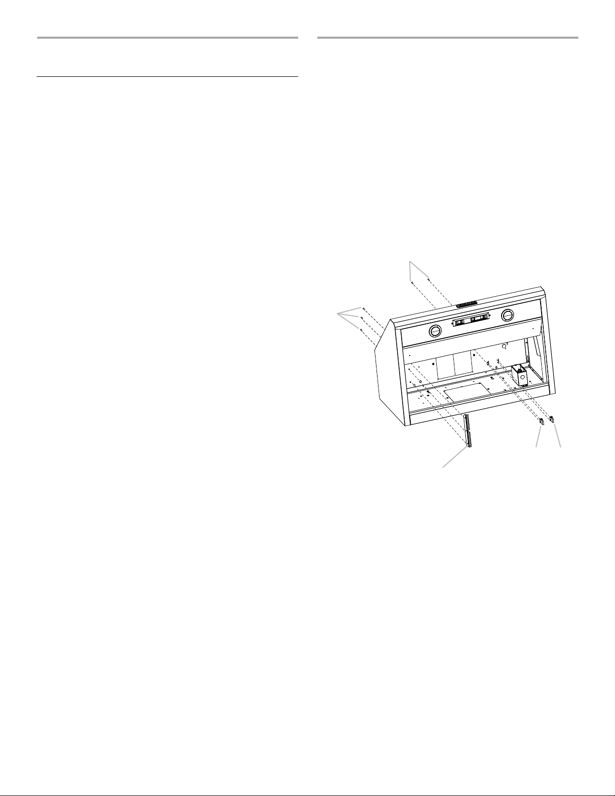
2. Install the motor support bracket using three 4.2 x 8 mm
screws. Screw bracket to the inside top or back (alternate
location on some models), toward the left side of the range
hood.
3. Install motor spring clip using two 4.2 x 8 mm screws. Screw
spring clip to the inside top or back (alternate location on
some models) of the range hood at the proper location for the
selected motor system. Slide the mounting tab of the spring
clip through the slot in the panel and secure with the screws.
Use the inside set of mounting holes for the single motor
system. Use the outside set of mounting holes for the dual
motor system.
B
A
E
D
C
A. 4.2 x 8 mm screws (3) for motor support bracket
B. 4.2 x 8 mm screws (2) for motor spring clip
C. Motor support bracket
D. Motor spring clip (single motor assembly location)
E. Motor spring clip (dual motor assembly location)
†®TORX is a registered trademark of Saturn Fasteners, Inc.
3

4. Install the 6 mm nuts to the outside top or outside back
A
(alternate location on some models) of the range hood at the
proper location for the selected motor system.
■ Two 6 mm nuts are required for the single motor system.
Clip nuts into the small square notches located at the left
and right end of the square vent opening.
■ Five 6 mm nuts are required for the dual motor system.
Clip nuts into the small square notches, one located in the
front of the square vent opening and the other four
located at the left and right ends of the square vent
opening.
A
A
B
Dual Blower Motor Assembly
A
A. Wiring connection
2. Slide the left mounting plate flange under the motor mounting
bracket.
A. Clip nut locations for dual motor assembly (5)
B. Clip nut locations for single motor assembly (2)
5. Mount range hood using the Installation Instructions that
came with your range hood model.
Install Range Hood Blower Motor
1. Install the range hood blower motor assembly inside the
range hood canopy with the wiring connection to the left for
the single motor system and to the front or top for the dual
motor system.
Single Blower Motor Assembly
A
A. Wiring connection
B
A
A. Motor mounting bracket
B. Mounting plate left flange
3. Run the power supply wires and connector through the hole
in the right end of the motor mounting plate.
A
B
A. Motor mounting plate hole
B. Power supply wires and connector
4
 Loading...