


GBS277PDB
Whirlpool GBS277PDB, KEBI141D, KEBS147D, KEBS177D, KEBS107D Technical Manual
...
TECHNICAL EDUCATION
ELECTRIC BUILT-IN
SINGLE OVEN
KAC-28
JOB AID 4317323

FORWARD
This Job Aid, “KitchenAid Electric Built-In Single Oven,” (Part No. 4317323), provides the
technician with information on the installation, operation, and service of the Electric Built-In Single
Oven. It is to be used as a training Job Aid and Service Manual. For specific information on the
model being serviced, refer to the “Use and Care Guide,” or “Tech Sheet” provided with the oven.
The Wiring Diagrams and Strip Circuits used in this Job Aid are typical and should be used for
training purposes only. Always use the Wiring Diagram supplied with the product when servicing
the unit.
GOALS AND OBJECTIVES
The goal of this Job Aid is to provide detailed information that will enable the service technician to
properly diagnose malfunctions and repair the KitchenAid Electric Built-In Single Oven.
The objectives of this Job Aid are to:
• Understand and follow proper safety precautions.
• Successfully troubleshoot and diagnose malfunctions.
• Successfully perform necessary repairs.
• Successfully return the oven to its proper operational status.
WHIRLPOOL CORPORATION assumes no responsibility for any repairs made
on our products by anyone other than Authorized Service Technicians.
Copyright © 2001, Whirlpool Corporation, Benton Harbor, MI 49022
- ii -

TABLE OF CONTENTS
Page
GENERAL............................................................................................................................... 1-1
Important Safety Information ............................................................................................. 1-1
KitchenAid Model & Serial Number Designations.............................................................. 1-2
Model & Serial Number Label And Tech Sheet Locations................................................. 1-3
Specifications..................................................................................................................... 1-4
KitchenAid Single Thermal Convection Oven Warranty .................................................... 1-7
KitchenAid Electric Built-In Oven Warranty ....................................................................... 1-8
INSTALLATION INFORMATION ........................................................................................... 2-1
Electrical Supply Requirements ......................................................................................... 2-1
Removing & Reinstalling The Oven Door .......................................................................... 2-3
Oven/Cooktop Combination-Approved Installation ............................................................ 2-4
THEORY OF OPERATION ..................................................................................................... 2-1
Air Flow .............................................................................................................................. 3-1
The Oven Shutdown Thermal Fuse ................................................................................... 3-2
The Oven Door Latch Assembly ........................................................................................ 3-3
How The Self-Clean Cycle Works ..................................................................................... 3-4
COMPONENT ACCESS ......................................................................................................... 4-1
Component Locations ........................................................................................................ 4-1
Removing The Oven Control/Display Boards And The Touch Panel Assembly................ 4-2
Removing The Power Supply Wiring Terminal Block And The Blower Motor ................... 4-4
Removing The Oven Light Transformer & The Control Power Transformer ..................... 4-6
Removing The Oven Door Latch Assembly....................................................................... 4-7
Removing An Oven Halogen Light And The Oven Temperature Sensor .......................... 4-8
Removing The Broil Element ........................................................................................... 4-10
Removing The Meat Probe Jack ..................................................................................... 4-11
Removing The Hidden Bake Element.............................................................................. 4-12
Removing The Convection Bake Element And The Fan Motor Assembly ...................... 4-14
Removing The Oven Shutdown Thermal Fuse................................................................ 4-16
Removing The Oven Door Glass, Hinges, & Handle ....................................................... 4-17
Removing The Oven Door Gasket................................................................................... 4-19
COMPONENT TESTING ........................................................................................................ 5-1
Blower Motor...................................................................................................................... 5-1
Oven Temperature Sensor ................................................................................................ 5-1
Convection Bake Element ................................................................................................. 5-2
Convection Fan Motor ....................................................................................................... 5-2
Broil Element ..................................................................................................................... 5-3
Bake Element .................................................................................................................... 5-3
Oven Door Latch Assembly ............................................................................................... 5-4
Oven Shutdown Thermal Fuse .......................................................................................... 5-4
Oven Light & Control Power Transformers ........................................................................ 5-5
- iii -

Page
DIAGNOSIS & TROUBLESHOOTING ................................................................................... 6-1
Diagnostics ........................................................................................................................ 6-1
Fahrenheit To Celsius Conversion .................................................................................... 6-1
Programming The Cavity Size ........................................................................................... 6-1
Electrostatic Discharge Sensitive Electronics .................................................................... 6-1
Failure/Error Display Codes............................................................................................... 6-2
Control Panel Test Locations............................................................................................. 6-3
Relay Logic Chart .............................................................................................................. 6-3
WIRING DIAGRAMS & STRIP CIRCUITS ............................................................................. 7-1
Model Number/Tech Sheet Use ........................................................................................ 7-1
Schematic Diagram ........................................................................................................... 7-2
Strip Circuits ...................................................................................................................... 7-3
- iv -
GENERAL
IMPORTANT SAFETY INFORMATION
Your safety and the safety of others is very important.
Important safety messages have been provided in this Job Aid. Always read and obey all
safety messages.
This is the safety alert symbol.
This symbol alerts you to hazards that can kill or hurt you
and others.
All safety messages will be preceded by the
safety alert symbol and the word “WARNING.”
All safety messages will identify the hazard, tell
you how to reduce the chance of injury, and tell
you what can happen if the instructions are not
followed.
WARNING
ELECTRICAL SHOCK HAZARD
Disconnect power before servicing.
Replace all panels before operating.
Failure to do so could result in death or
electrical shock.
ELECTROSTATIC DISCHARGE
(ESD) SENSITIVE ELECTRONICS
ESD problems are present everywhere. ESD
may damage or weaken the electronic control
assembly. The new control assembly may appear to work well after repair is finished, but
failure may occur at a later date due to ESD
stress.
• Use an antistatic wrist strap. Connect the
wrist strap to a green ground connection
point or unpainted metal in the appliance;
or touch your finger repeatedly to a green
ground connection point or unpainted metal
in the appliance.
• Before removing the part from its package, touch the antistatic bag to a green
ground connection point or unpainted metal
in the appliance.
• Avoid touching electronic parts or terminal
contacts. Handle the electronic control
assembly by the edges only.
• When repackaging the failed electronic
control assembly in an antistatic bag, observe the above instructions.
1-1

KITCHENAID MODEL & SERIAL NUMBER DESIGNATIONS
MODEL NUMBER
MODEL NUMBER K EB S 10 7 D S S 8
INTERNATIONAL SALES IND.
OR MARKETING CHANNEL
IF PRESENT
PRODUCT GROUP
K = KITCHENAID BRAND
PRODUCT IDENTIFICATION
EB = ELECTRIC BUILT-IN OVEN
EH = ELECTRIC BUILT-IN HI SPEED COMBO
EM = ELECTRIC BUILT-IN MICRO COMBO
EW = ELECTRIC WARMING OVEN
GB = GAS BUILT-IN OVEN
GM = GAS BUILT-IN MICRO COMBO OVEN
MERCHANDISING SCHEME
C = FLUSH LOOK
D = DRAWER
I = IMPERIAL
N = INTERNATIONAL COLLECTION EUROPEAN
S = SUPERBA
CAPACITY / SIZE / SERIES / CONFIGURATION
1ST POSITION 2ND POSITION
1 = SINGLE OVEN 4 = 24˝ WIDE
2 = DOUBLE OVEN 6 = 36˝ WIDE
3 = COMBO OVEN 7 = 27˝ WIDE
4 = OVEN W/DRAWER 0 = 30˝ WIDE
5 = MINI OVEN
6 = COMBO W/MINI OVEN
FEATURES
0 = STANDARD FEATURES
1 = STANDARD FEATURES / ELECTRIC CLOCK
5 = DELUXE FEATURES
6 = DELUXE FEATURES / ELECTRIC CLOCK
7 = DELUXE FEATURES / THERMAL CONVECTION
8 = DOUBLE THERMAL CONVECTION
9 = MULTIMODE
YEAR OF INTRODUCTION
D = 1995, G = 1998, H = 1999, J = 2000
COLOR CODE
AL = ALMOND, BL = BLACK, BT = BISCUIT,
WH = WHITE, SS = BRUSHED STAINLESS STEEL
ENGINEERING CHANGE (0, 1, 2, ETC.)
SERIAL NUMBER
SERIAL NUMBER X K 0 3 01006
MANUFACTURING SITE
X = OXFORD
YEAR OF PRODUCTION
K = 2000, L = 2001, M = 2002
WEEK OF PRODUCTION
3RD WEEK
PRODUCT SEQUENCE NUMBER
1-2
MODEL & SERIAL NUMBER LABEL
AND TECH SHEET LOCATIONS
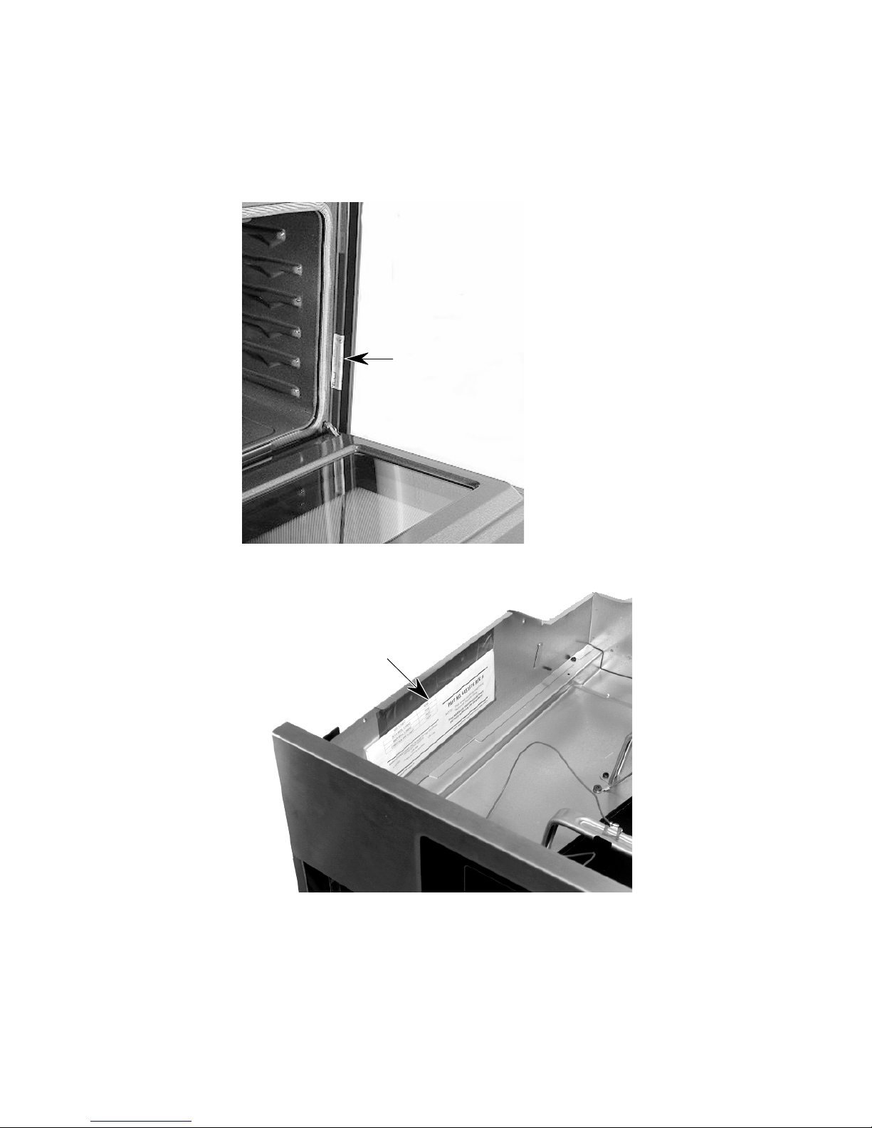
The Model/Serial Number label and Tech Sheet locations are shown below.
Model & Serial Number Location
Tech Sheet Location
(Below Top Front Cover)
1-3
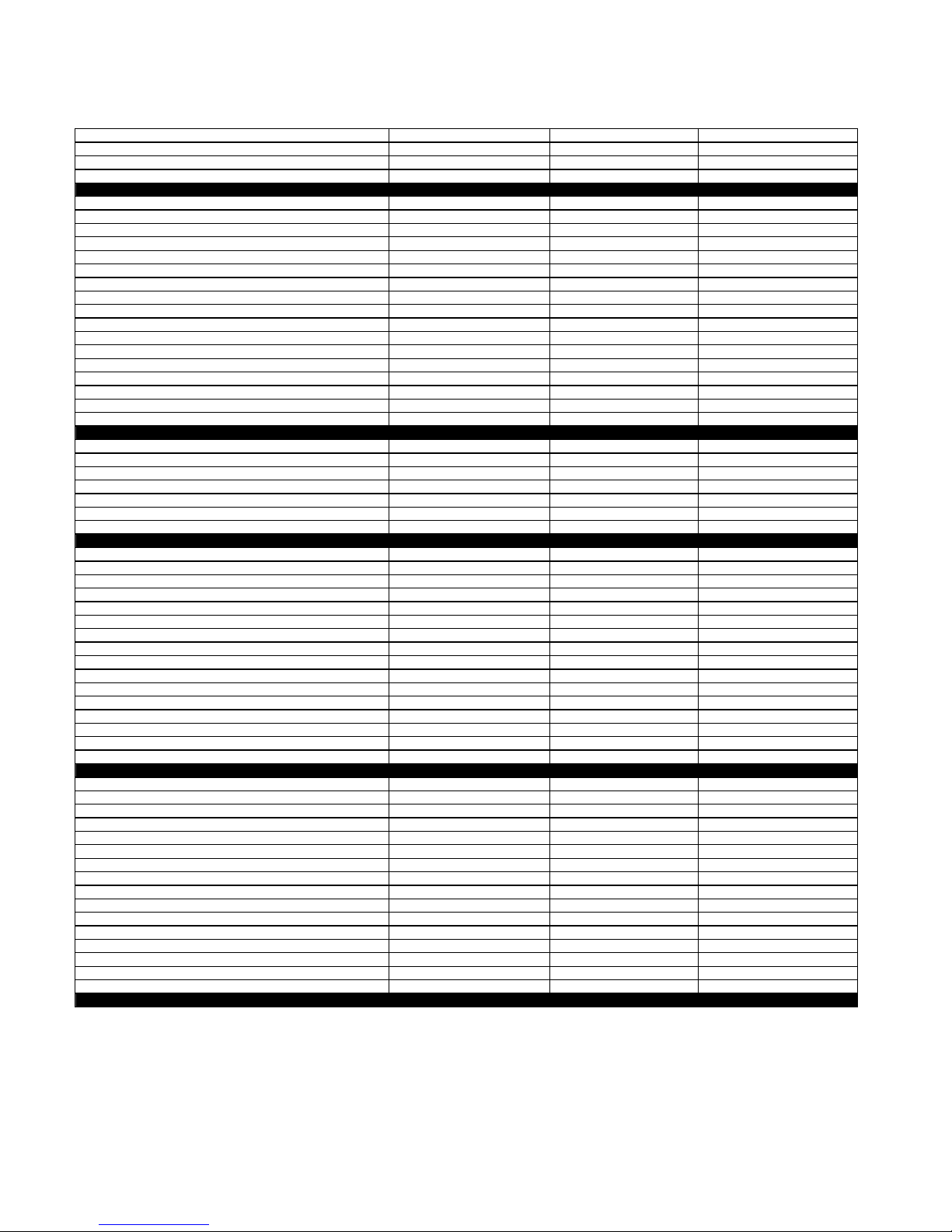
SPECIFICATIONS
Model Number
Colors Available
Model Description
Size-Configuration
Dimensions/Specifications
Overall Height (in)
Overall Width (in)
Overall Depth Inc Hrdwr/Hndl (in)
Depth W/O Handle (in)
Cutout Dimensions
Cutout Height (in) (Measure Or Min/Max)
Cutout Width (in) (Measure Or Min/Max)
Cutout Depth (in) (Measure Or Min/Max)
Other Dimensions
Conduit Size (in) (Length/Diameter)
Net Weight (lbs)
Shipping Weight (lbs)
Total Connected Load in kW
240 Volts
208 Volts
240/120V AC
Circuit Amps
Exterior
Oven Front Frame
Oven Control Type
Bake
Maxi Broil
Econo Broil
Convection
Child Lock Out
Interior
Main Oven
Cooking System
Cleaning System
Auto Self Clean Latch
Main Oven Liner Finish
Main Oven Volume (cu ft)
Main Oven Height (in)
Main Oven Width (in)
Main Oven Depth (in)
Main Electric Oven
Main Hidden Bake Element
Main Electric Element Output
Main Oven Bake (w@240/208v)
Main Oven Broil Inner Element (w@240/208v)
Main Oven Broil Outer Element (w@240/208)
Main Oven Convection )w@240/208v)
Miscellaneous
Cookbook Part/Comment
Installation Instructions Part/Comment
Service Manual Part/Comment
Tech Sheet Part/Comment
Use & Care Guide Oven Part/Comment
Other
Agency Approvals
Installation Hardware
Residential Use Only
Under Counter Capability
Warranty
Full (Months)
Extended
Electronic Controls (Months)
Electrical Elements (Months)
Porcelain Liner/Door (Months)
KEBI141D KEBS147D KEBS177D
BL, WH BL, WH S S
Single Built-In Oven Single Built-In Oven Single Built-In Oven
24" 24" 27"
28 7/8" 28 7/8" 28 7/8"
23 3/4" 23 3/4" 26 3/4"
25 1/8" 25 1/8" 25 1/8"
23 7/8" 23 7/8" 23 7/8"
27 3/4" 27 3/4" 27 3/4"
22 1/2" 22 1/2" 25 1/2"
23 1/4" 23 1/4" 23 1/4"
48"; 1/2" 48"; 1/2" 48"; 1/2"
115 121 12 6
123 129 134
4.9 kw 4.9 kw 4.9 kw
3.7 kw 3.7 kw 3.7 kw
30 AMP 30 AMP 30 AMP
Porcelain Porcelain Porcelain
Electronic Electronic Electronic
Standard Standard Standard
Yes Yes Yes
Yes Yes Yes
3rd Element
Yes Yes Yes
True Convection True Convection
Self Cleaning Self Cleaning Self Cleaning
Yes Yes Yes
Porcelain Porcelain Porcelain
3.27 3.09 3.58
16" 16" 16"
19" 19" 2 2"
18 1/2" 18 1/2" 18 1/2"
Yes Yes Yes
2000W/1500W 2000W/1500W 2000W/1500W
1667W/1250W 1667W/1250W 1667W/1250W
1000W/750W 1000W/750W 1000W/750W
1600W/1200W 1600W/1200W
4449066 4449066
4448970 4448970 4450411
4317323 4317323 4317323
4451876 4451876 4451876
4448999 4449000 4450571
UL, CSA UL, CSA UL, CSA
Yes Yes Yes
Yes Yes Yes
Yes Yes Yes
12 12 12
60 60 60
60 60 60
120 120 120
1-4
Model Number
Colors Available
Model Description
Size-Configuration
Dimensions/Specifications
Overall Height (in)
Overall Width (in)
Overall Depth Inc Hrdwr/Hndl (in)
Depth W/O Handle (in)
Cutout Dimensions
Cutout Height (in) (Measure Or Min/Max)
Cutout Width (in) (Measure Or Min/Max)
Cutout Depth (in) (Measure Or Min/Max)
Other Dimensions
Conduit Size (in) (Length/Diameter)
Net Weight (lbs)
Shipping Weight (lbs)
Total Connected Load in kW
240 Volts
208 Volts
240/120V AC
Circuit Amps
Exterior
Oven Front Frame
Oven Control Type
Bake
Maxi Broil
Econo Broil
Convection
Child Lock Out
Interior
Main Oven
Cooking System
Cleaning System
Auto Self Clean Latch
Main Oven Liner Finish
Main Oven Volume (cu ft)
Main Oven Height (in)
Main Oven Width (in)
Main Oven Depth (in)
Main Electric Oven
Main Hidden Bake Element
Main Electric Element Output
Main Oven Bake (w@240/208v)
Main Oven Broil Inner Element (w@240/208v)
Main Oven Broil Outer Element (w@240/208)
Main Oven Convection )w@240/208v)
Miscellaneous
Cookbook Part/Comment
Installation Instructions Part/Comment
Service Manual Part/Comment
Tech Sheet Part/Comment
Use & Care Guide Oven Part/Comment
Other
Agency Approvals
Installation Hardware
Residential Use Only
Under Counter Capability
Warranty
Full (Months)
Extended
Electronic Controls (Months)
Electrical Elements (Months)
Porcelain Liner/Door (Months)
KEBS107D KEBC177H
S S BT, BL, WH
Single Built-In Oven Single Built-In Oven
30" 27"
28 7/8" 28 7/8"
29 3/4" 26 3/4"
25 1/8" 25 1/8"
23 7/8" 23 7/8"
27 3/4" 27 3/4"
28 1/2" 25 1/2"
23 1/4" 23 1/4"
48"; 1/2" 48"; 1/2"
126 126
139 134
4.9 kw 4.9 kw
3.7 kw 3.7 kw
30 AMP 30 AMP
Porcelain Porcelain
Electronic Electronic
Standard Standard
Yes Yes
Yes Yes
3rd Element 3rd Element
Yes Yes
True Convection True Convection
Self Cleaning Self Cleaning
Yes Yes
Porcelain Porcelain
4.24 3.58
16" 16"
25" 22"
18 1/2" 18 1/2"
Yes Yes
2000W/1500W 2000W/1500W
1667W/1250W 1667W/1250W
1000W/750W 1000W/750W
1600W/1200W 1600W/1200W
4449066 4449066
4450411 4448970
4317323 4317323
4451876 4451876
4450571 4449000
UL, CSA UL, CSA
Yes Yes
Yes Yes
Yes Yes
12 12
60 60
60 60
120 120
1-5
Model Number
Colors Available
Model Description
Size-Configuration
Dimensions/Specifications
Overall Height (in)
Overall Width (in)
Overall Depth Inc Hrdwr/Hndl (in)
Depth W/O Handle (in)
Cutout Dimensions
Cutout Height (in) (Measure Or Min/Max)
Cutout Width (in) (Measure Or Min/Max)
Cutout Depth (in) (Measure Or Min/Max)
Other Dimensions
Conduit Size (in) (Length/Diameter)
Net Weight (lbs)
Shipping Weight (lbs)
Total Connected Load in kW
240 Volts
208 Volts
240/120V AC
Circuit Amps
Exterior
Oven Front Frame
Oven Control Type
Bake
Maxi Broil
Econo Broil
Convection
Child Lock Out
Interior
Main Oven
Cooking System
Cleaning System
Auto Self Clean Latch
Main Oven Liner Finish
Main Oven Volume (cu ft)
Main Oven Height (in)
Main Oven Width (in)
Main Oven Depth (in)
Main Electric Oven
Main Hidden Bake Element
Main Electric Element Output
Main Oven Bake (w@240/208v)
Main Oven Broil Inner Element (w@240/208v)
Main Oven Broil Outer Element (w@240/208)
Main Oven Convection )w@240/208v)
Miscellaneous
Cookbook Part/Comment
Installation Instructions Part/Comment
Service Manual Part/Comment
Tech Sheet Part/Comment
Use & Care Guide Oven Part/Comment
Other
Agency Approvals
Installation Hardware
Residential Use Only
Under Counter Capability
Warranty
Full (Months)
Extended
Electronic Controls (Months)
Electrical Elements (Months)
Porcelain Liner/Door (Months)
KEBC107H KEBC107H
BT, WH BL
Single Built-In Oven Single Built-In Oven
30" 30"
28 7/8" 28 7/8"
29 3/4" 29 3/4"
25 1/8" 25 1/8"
23 7/8" 23 7/8"
27 3/4" 27 3/4"
28 1/2" 28 1/2"
23 1/4" 23 1/4"
48"; 1/2" 48"; 1/2"
131 131
139 139
4.9 kw 4.9 kw
3.7 kw 3.7 kw
30 AMP 30 AMP
Porcelain Porcelain
Electronic Electronic
Standard Standard
Yes Yes
Yes Yes
3rd Element 3rd Element
Yes Yes
True Convection True Convection
Self Cleaning Self Cleaning
Yes Yes
Porcelain Porcelain
4.07 4.07
16" 16"
25" 25"
18 1/2" 18 1/2"
Yes Yes
2000W/1500W 2000W/1500W
1667W/1250W 1667W/1250W
1000W/750W 1000W/750W
1600W/1200W 1600W/1200W
4449066 4449066
4448970 4448970
4317323 4317323
4451876 4451876
4449000 4449000
UL, CSA UL, CSA
Yes Yes
Yes Yes
Yes Yes
12 12
60 60
60 60
120 120
1-6

KITCHENAID SINGLE THERMAL
CONVECTION OVEN WARRANTY
LENGTH OF WARRANTY
FULL ONE YEAR WARRANTY
From Date of Purchase.
FIVE YEAR LIMITED WARRANTY
2nd through 5th Year
TEN YEAR LIMITED WARRANTY
2nd through 10th Year
KITCHENAID WILL NOT PAY FOR:
A. Service calls to:
1. Correct the installation of the oven.
2. Instruct you how to use the oven.
3. Replace house fuses or correct house wiring or plumbing.
4. Replace owner-accessible light bulbs.
B. Repairs when oven is used in other than normal, single family household use.
C. Pickup and delivery. Your oven is designed to be repaired in the home.
D. Damage to your oven caused by accident, misuse, fire, flood, acts of God, or use of products not approved
by Whirlpool.
E. Repairs to parts or systems caused by unauthorized modifications made to the appliance.
KITCHENAID SHALL NOT BE LIABLE FOR INCIDENTAL OR CONSEQUENTIAL DAMAGES. Some states do
not allow the exclusion or limitation of incidental or consequential damages, so this exclusion or limitation may not
apply to you. This warranty gives you special legal rights, and you may also have other rights which vary from stateto-state.
Outside the United States, a different warranty may apply. For details, please contact your authorized Whirlpool or
KitchenAid distributor or military exchange.
If you need service first see the “Troubleshooting” section of the Use and Care Guide. After checking ”Troubleshooting,” additional help can be found by checking the “Requesting Assistance or Service” section, or by calling
our Consumer Assistance Center telephone number from anywhere in the U.S.A.
KitchenAid: 1-800-422-1230 Benton Harbor, Michigan 49022
Canadian Residents call: 1-800-461-5681
KITCHENAID WILL PAY FOR:
Replacement parts and repair labor to correct defects in materials or workmanship. Service must be provided by an authorized KitchenAid service company.
Parts only.
Electric element, electronic control, & convection element.
Parts only.
Oven cavity and inner door.
1-7

KITCHENAID ELECTRIC
BUILT-IN OVEN WARRANTY
LENGTH OF
WARRANTY:
ONE-YEAR FULL
WARRANTY
From Date of
Purchase.
SECOND-THROUGH
FIFTH-YEAR
LIMITED WARRANTY
From Date of
Purchase.
KITCHENAID
WILL PAY FOR:
Replacement parts
and repair labor costs
to correct defects in
materials or workmanship. Service must be
provided by a KitchenAid designated servicing company.
Replacement parts for
any oven electric
element to correct
defects in materials or
workmanship. Replacement parts for
solid state touch
control system to
correct defects in
materials or workmanship.
KITCHENAID
WILL NOT PAY FOR:
A. Service calls to:
1. Correct the installation of the oven.
2. Instruct you how to use the oven.
3. Replace house fuses or correct house wiring.
B. Repairs when oven is used in other than normal
home use.
C. Damage resulting from accident, alteration, misuse,
abuse, acts of God, improper installation, or installation not in accordance with local electrical codes.
D. Any labor costs during the limited warranties.
E. Replacement parts or repair labor costs for units
operated outside the United States and Canada.
F. Pickup and delivery. This product is designed to be
repaired in the home.
G. Repairs to parts or systems resulting from unautho-
rized modifications made to the appliance.
H. In Canada, travel or transportation expenses for
customers who reside in remote areas.
SECOND-THROUGH
TENTH-YEAR
LIMITED WARRANTY
From Date of
Purchase.
KITCHENAID AND KITCHENAID CANADA DO NOT ASSUME ANY RESPONSIBILITY FOR INCIDENTAL OR
CONSEQUENTIAL DAMAGES. Some states or provinces do not allow the exclusion or limitation of incidental or
consequential damages, so this exclusion or limitation may not apply to you. This warranty gives specific legal
rights and you may also have other rights which vary from state to state or province to province.
Outside the United States and Canada, a different warranty may apply. For details, please contact your
authorized KitchenAid dealer.
If you need assistance or service, first see the “Diagnosis & Troubleshooting” section of this book. After checking
“Diagnosis & Troubleshooting,” additional help can be found by checking the “Requesting Assistance or Service”
section in the Use And Care Guide. In the U.S.A., call our Consumer Assistance Center at: 1-800-422-1230. In
Canada, call KitchenAid Canada at: 1-800-807-6777.
Replacement parts for
the porcelain oven
cavity/inner door if the
part rusts through due
to defects in materials
or workmanship.
1-8

INSTALLATION INFORMATION
ELECTRICAL SUPPLY REQUIREMENTS
WARNING
ELECTRICAL SHOCK HAZARD
• An electrical ground is required on this
appliance.
• Do not use an extension cord with this
appliance.
• If a cold water pipe is interrupted by plastic, nonmetallic gaskets, or other insulating materials, do not use for grounding.
• Do not ground to a gas pipe.
• Do not use a fuse in the neutral or grounding circuit. It could result in an electrical
shock.
• Check with a qualified electrician if you are
in doubt as to whether the appliance is
properly grounded.
Failure to follow these instructions could
result in death or serious injury.
GENERAL
If codes permit, and a separate grounding wire
is used, it is recommended that a qualified electrician determine that the grounding path and
wire gauge are in accordance with local codes.
The following information applies to the builtin electric wall oven wiring:
• The oven must be connected to the proper
electrical voltage and frequency as specified
on the model/serial rating plate (located on
the oven frame).
• The oven must be connected with copper
wire only.
• Wire sizes and connections must conform to
the requirements of the National Electrical
Code, ANSI/NFPA 70—latest edition*, and
all local codes and ordinances. Wire sizes
and connections must conform with the rating of the appliance. Copies of the standards
listed above may be obtained from:
* National Fire Protection Association
Batterymarch Park
Quincy, Massachusetts 02269
• The oven should be connected directly to a
time delay fuse or circuit breaker through
flexible, armored, or nonmetallic sheathed,
copper cable. The flexible, armored cable
that extends from the appliance should be
connected directly to the junction box.
• Fuse both sides of the line.
• Locate the junction box to allow as much
slack as possible between the junction box
and the appliance so that the appliance can
be moved if servicing is ever necessary. Do
not cut the conduit.
• A U.L.-listed conduit connector must be provided at the junction box.
• Wiring diagrams are located in Section 7 of
this Job Aid.
• A Tech Sheet is located below the top access cover on all models.
• Models rated from 7.3 to 9.6 kW at 240-volts,
(6.5 to 7.2 kW at 208-volts), require a separate 40-ampere circuit. Models rated at 7.2
kW and below at 240-volts, (5.4 kW and
below at 208-volts), require a separate 30ampere circuit.
2-1
ELECTRICAL WIRING
WARNING
ELECTRICAL SHOCK HAZARD
• An electrical ground is required on this
appliance.
• Do not connect to the electrical supply
until the appliance is permanently
grounded.
• Turn off power to the junction box before
making the electrical connections.
• Connect the appliance to a grounded,
metallic, permanent wiring system.
Failure to follow these instructions could
result in death or serious injury.
1. Insert the end of the flexible conduit through
the cabinet opening to the junction box
inlet.
2. Disconnect the power going to the junction box.
3. Open the junction box cover and connect
the flexible conduit to the U.L.-listed conduit connector.
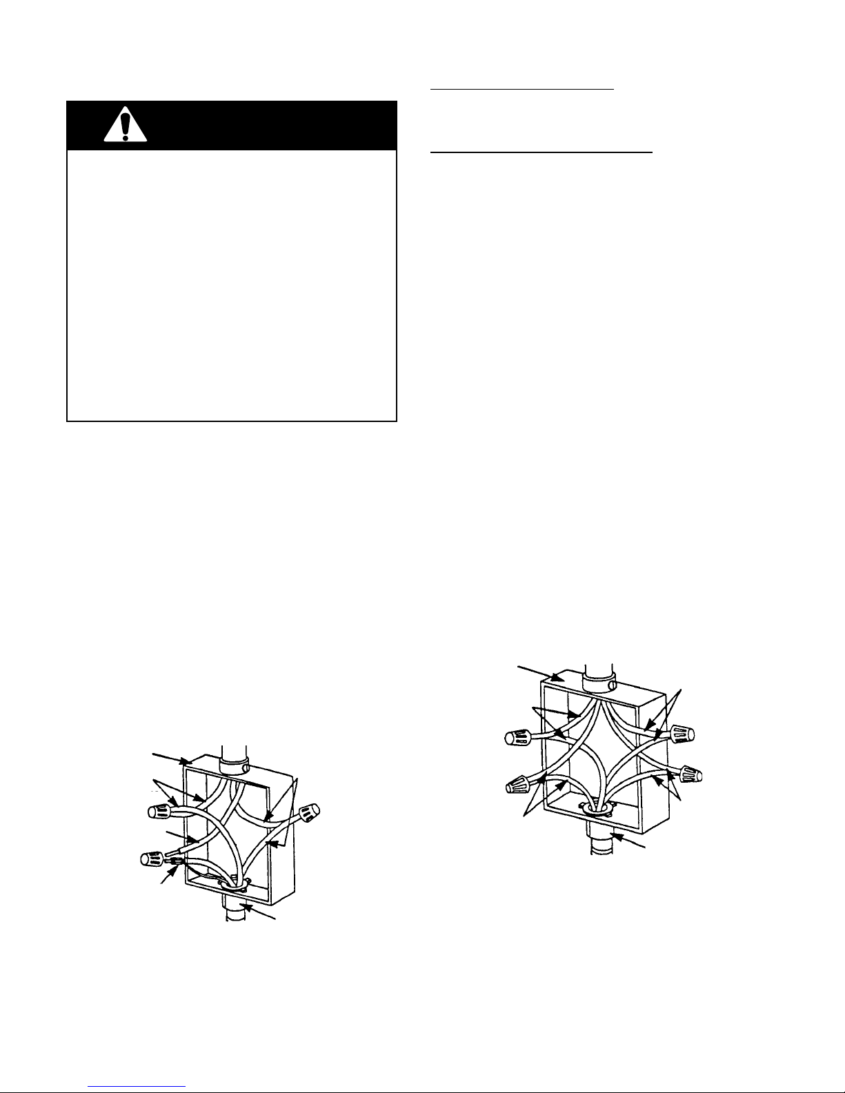
4. Connect the ends of the black wires together with twist-on connectors (see the
illustration below).
5. Connect the ends of the red wires together
with twist-on connectors.
cable from
power supply
junction box
red wires
black wires
If local codes DO permit connecting the cabinet-grounding conductor to a neutral junction
box wire, perform steps 6 and 7.
If local codes DO NOT permit connecting the
cabinet-grounding conductor to a neutral junction box wire, or if you are connecting the
appliance to a 4-wire electrical system, perform steps 8 through 11.
6. Connect the factory-crimped bare and
white electrical wires coming from the
appliance conduit cable to the white (neutral) wire inside the junction box (see the
illustration below).
7. Replace the junction box cover.
8. Separate the factory-crimped bare and
white electrical wires coming from the
appliance conduit cable.
9. Connect the white appliance wire to the
white (neutral) wire inside the junction
box.
10. Connect the bare grounding wire from the
appliance to a grounded wire inside the
junction box. IMPORTANT: Do not con-
nect the bare grounding wire to the
white (neutral) wire in the junction box.
11. Replace the junction box cover.
cable from
power supply
junction box
white wires
red wires
white wire
white & bare
grounding
appliance wires
factory crimped cable from
oven
Crimped Grounding Conductors
To White (Neutral) Wire
U.L.-listed
connector
conduit
2-2
bare
grounding
appliance wires
cable from
oven
Separate Grounding Conductors
To White (Neutral) & Bare Wires
U.L.-listed
conduit
connector
black wires
REMOVING & REINSTALLING THE OVEN DOOR
WARNING
PERSONAL INJURY HAZARD
• Use both hands to remove oven doors.
• Do not use the handle or any portion of the
front frame or trim for lifting.
• Because of the weight and size of the
oven, two or more people are required to
move and safely install it.
Failure to properly grasp the oven doors or to
lift the oven properly could result in personal
injury or damage to the product.
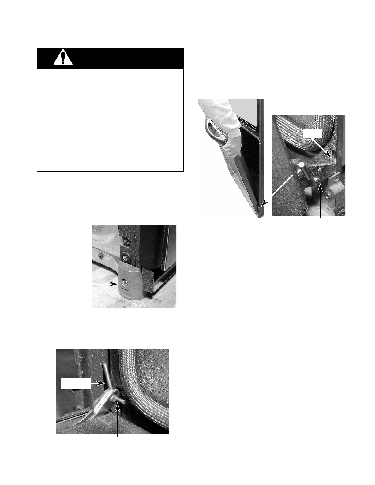
CAUTION: Do not remove the shipping base
or the shipping feet at the front lower corners of the oven. The shipping feet will
protect the lower oven trim until the oven is
inserted into the cabinet cutout.
2. Close the oven door as far as the two pins
will allow.
3. Grasp the sides of the door and lift the door
until it stops, then pull the hinge hangers
out of the slots.
Slot
Hinge Hanger
Shipping Foot
To remove the oven door:
1. Install a pin in the hole of each oven door
hinge hanger.
Door Pin
To reinstall the oven door:
1. Grasp the sides of the door and tilt it back
at a slight angle, then insert the hinge
hangers into the hinge slots as far as they
will go.
2. Rotate the top of the door towards the
oven so the hinge hangers fit onto the
support pins.
3. Close the oven door as far as the pins will
allow, and make sure that the hinge hangers are fully seated on the support pins. If
they are not seated properly, the door will
not close tightly and may be off-center. To
seat the hinge hangers, open the door
slightly, and push in on the bottom until the
hangers are fully seated.
4. Open the oven door to its fully open position and remove the two hinge hanger
pins.
5. Close the oven door completely and check
it for proper operation and alignment.
Door Pin Into Hinge Hanger Hole
2-3
OVEN / COOKTOP
COMBINATION-APPROVED INSTALLATION
The following built-in ovens are approved for installation over electric and gas cooktops, as noted.
U.S. MODELS
BUILT-IN OVENS
KEBI141D / KEBS147D / KEBI171D / KEBS177D / KEBI101D
KEBS107D / GBS277PD / GBS307PD / RBS240PD / RBS245PD
RBS270PD / RBS275PD / RBS277PD / RBS305PD / RBS307PD
ELECTRIC COOKTOPS GAS COOKTOPS
KECC563H KGCT055G
KECC501G KGCT305G
KECC502G KGCT365G
KECC507G KGCT366G
KECC508G GLT3014G
KECC562G GLT3614G
KECC576G GLT3615G
KECC568G KGCS105G
RCC3024G KGCS166G
GJC3034G KGCS127G
GJC3634G SCS3004G
KECS100G SCS3014G
KECS161G SCS3614G
RCS3004G KGCT305E
RCS3014G KGCT365E
RCS3614G KGCT366E
GJ8646XD SC8640ED
KECC501B SC8830EB
KECC502B SC8836EB
KECC507B GL8856EB
KECC560B
KECC567B
GJ8640XB
RC8600XB
RC8640XB
RC8200XB
RC8400XB
KECS100S
CANADIAN MODELS
YRBS275PD / YRBS277PD / YRBS305PD / YRBS307PD
BUILT-IN OVENS
YKEBS177D / YKEBS107D / YKEBI101D / YGBS277PD
ELECTRIC COOKTOPS
YKECC502G
YKECC507G
YKECC567G
GJC3034G
GJC3634G
RCC3024G
RCS3014G
2-4
THEORY OF OPERATION
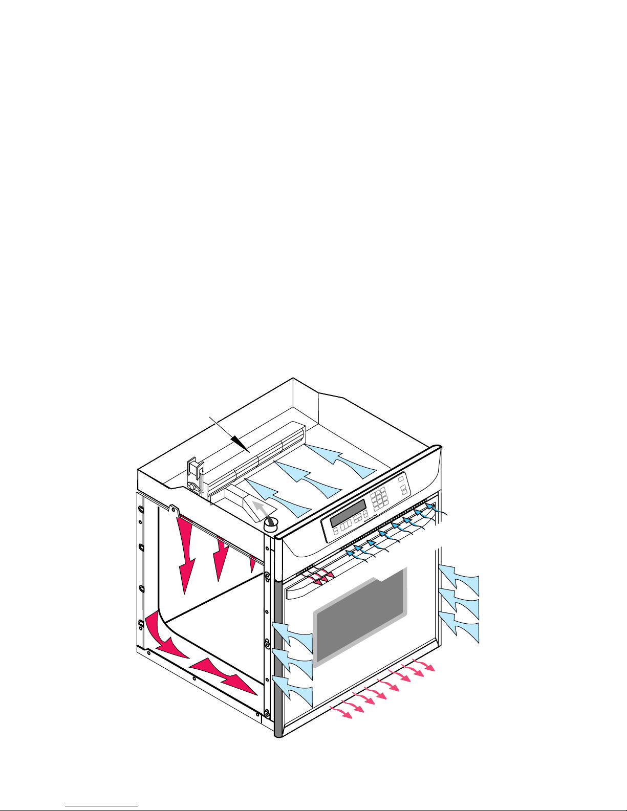
AIR FLOW
Intake air is drawn into the oven at two locations: through the control panel vent, (over the
latch assembly and the inner chassis top), and
through the side mounting rails (over the oven
sides and around the back). Air also enters the
oven at the back through the openings on the
upper section of the rear cover. At this point,
the air from the sides and the top mix. The air
is then pulled through the blower, down the
back of the unit between the outer and inner
rear covers, and out the front of the unit via the
bottom vent trim.
Air from the blower is forced over the cavity
vent. The pressure differential causes air to be
drawn from the cavity, where the air exits
through a small opening on the left side of the
control panel vent.
Air passes through the oven door by a combination of natural and forced convection. Air
enters the door through the bottom slots, and
passes between the outer glass, and the angled
inner glass. This air exits through the top slots
in the door via natural convection. Air also
enters the bottom of the door, and is drawn
between the two pieces of inner door glass,
where it exits through the top slots in the upper
part of the door. This air is then drawn into the
blower, and is forced down the back of the unit
between the inner and outer chassis covers,
and finally out the bottom vent.
The purpose of the convection fan is to circulate hot air inside the oven cavity, not to evacuate the air. Thus, the air flow for the convection
models and the non-convection models, is the
same.
BLOWER
INTAKE AIR
EXHAUST AIR
INTAKE AIR
OVEN
EXHAUST AIR
3-1
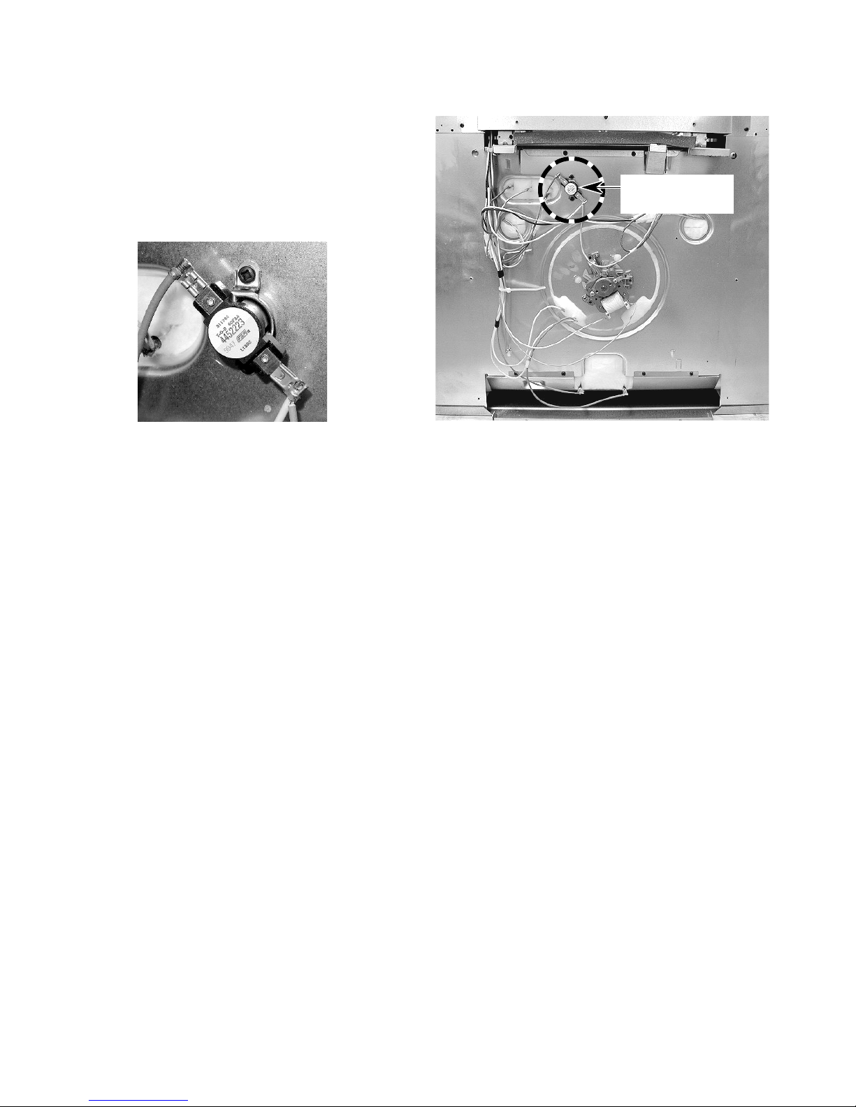
THE OVEN SHUTDOWN THERMAL FUSE
The thermal fuse is located on the rear of the
oven at the indicated location. The oven shutdown thermal fuse opens L2 to the oven if the
temperature at the rear panel exceeds 160˚C/
320˚F. The fuse is a one-time, non-resettable
safety device.
Oven Shutdown
Thermal Fuse
Oven Shutdown Thermal Fuse
BACK OF OVEN
3-2
 Loading...