


Electric Slide-In Range
Installation Instructions
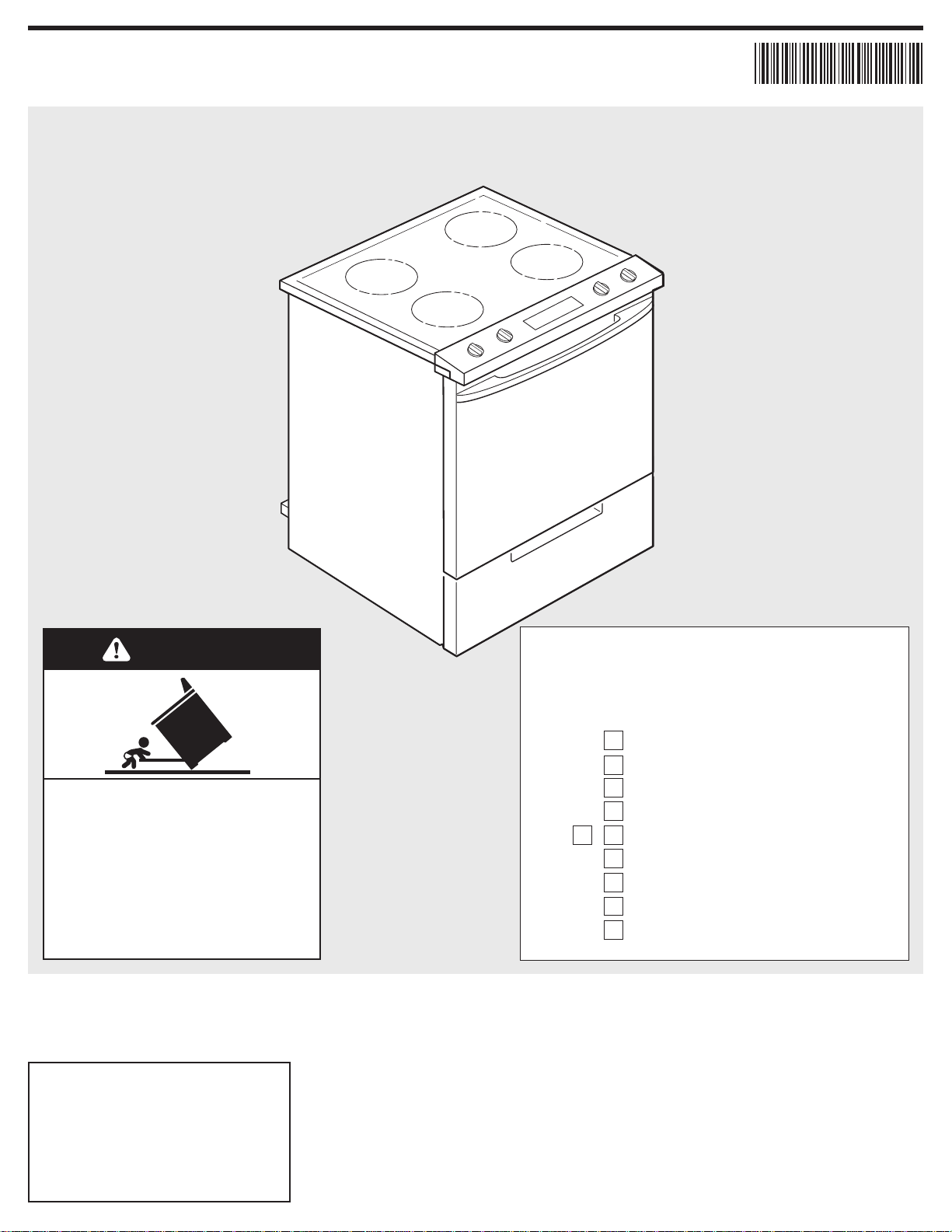
30" Electric Slide-In Range
1
9758642
9758642
Quick Reference
Ta ble of Contents:
Pages
2
3
3
4
5 - 8
9
Before you start
Product dimensions
Cabinet dimensions/requirements
Electrical requirements
Installation steps
Check operation
If range does not operate
If you need assistance/service
Moving the range
Part No. 9758642
WARNING
Tip Over Hazard
Achild or adult can tip the range and
be killed.
Connect anti-tip bracket to rear
range foot.
Reconnect the anti-tip bracket, if the
range is moved.
Failure to follow these instructions can
result in death or serious burns to
children and adults.
10
10
10
www.whirlpool.com
IMPORTANT:
Installer: Leave Installation
Instructions with the homeowner.
Homeowner: Keep Installation
Instructions for future reference.
Read and save these instructions for
local electrical inspector’s use.
Write down the model and serial
numbers before installing range.
Both numbers are listed on the
model/serial rating plate located
on the oven frame behind the
storage drawer panel.
Model # _______________________________
Serial # _______________________________
IMPORTANT:
Read and save these instructions.
2
Before you start...
Mobile home installation
The installation of this range must
conform with the Manufactured Home
Construction and Safety Standard, Title
24 CFR, Part 3280 [formerly the Federal
Standard for Mobile Home Construction
and Safety, Title 24, HUD (Part 280)] or,
when such standard is not applicable, the
Standard for Manufactured Home
Installations, ANSI A225.1/NFPA 501A*,
or with local codes.
When this range is installed in a mobile
home, it must be secured to the floor
during transit. Any method of securing
the range is adequate as long as it
conforms to the standards listed above.
Four-wire power supply cord or cable
must be used in a mobile home
installation. The appliance wiring will
need to be revised. See “Four-wire
electrical connection” section.
Tools needed:
Follow all factory safety instructions
included with your tools.
• level
• flat-blade screwdriver
• 3/8" drive ratchet
• 3/8" and 5/16" nut drivers
• hand or electric drill
• channel lock pliers
• safety glasses
• gloves
• measuring tape or ruler
• wood floors: 1/8" drill bit
• concrete/ceramic floors:
3/16" carbide-tipped masonry drill bit
(Hammer may be needed for anchors.)
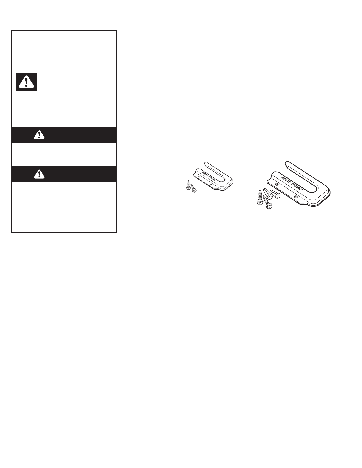
Parts supplied:
Brackets must be securely mounted to sub-floor.
Thickness of flooring may require longer screws to
anchor bracket to sub-floor. Longer screws are
available from your local hardware store.
Not shown:
literature pack
floor-mounted
anti-tip bracket
2 screws
(#10 x 1-1/2")
Copies of the standards listed may be obtained
from:
* National Fire Protection Association
One Batterymarch Park
Quincy, Massachusetts, 02269
The floor anti-tip
bracket must be
installed. To install
the anti-tip bracket
shipped with the
range, see Page 5 and
the anti-tip bracket template.
IMPORTANT: Observe all governing codes
and ordinances. Failure to meet codes
and ordinances could lead to fire or
electrical shock.
Proper installation is your responsibility.
A qualified technician must install this
range. Make sure you have everything
necessary for correct installation. It is the
installer’s responsibility to comply with
installation clearances specified on the
model/serial rating plate. The model/serial
rating plate is located on the oven frame
behind the storage drawer panel.
Check location where range will be
installed. The range should be located for
convenient use in kitchen.
To eliminate the risk of burns or fire by
reaching over heated surface units,
cabinet storage space located above the
surface units should be avoided. If
cabinet storage is to be provided, the risk
can be reduced by installing a range
hood that projects horizontally a
minimum of 5 inches beyond the bottom
of the cabinets.
All openings in the wall or floor where
ranges is to be installed must be sealed.
Cabinet opening dimensions that are
shown must be used. Given dimensions
are minimum clearances.
Grounded electrical outlet is required.
See “Electrical requirements” section.
2 plastic
anchors
Your safety and the safety of
others are very important.
We have provided many important safety
messages in this manual and on your
appliance.Always read and obey all
safety messages.
This is the safety alert symbol.
This symbol alerts you to
potential hazards that can kill
or hurt you and others.
All safety messages will follow the safety
alert symbol and either the word
“DANGER”or “WARNING.”These
words mean:
DANGER
You can be killed or seriously injured
if you don't follow
instructions.
immediately
WARNING
You can be killed or seriously injured
if you don't follow instructions.
All safety messages will tell you what the
potential hazard is, tell you how to
reduce the chance of injury,and tell you
what can happen if the instructions are
not followed.
3
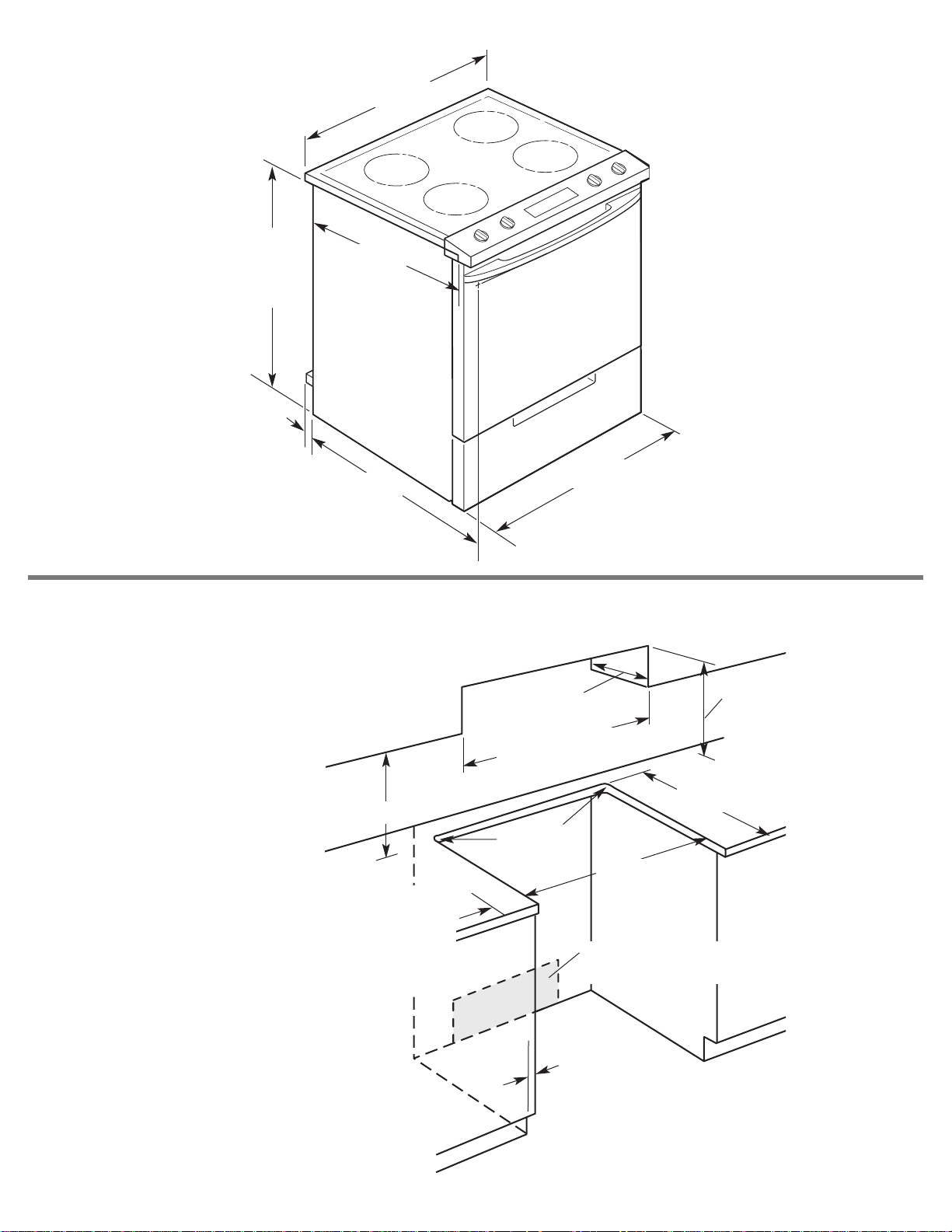
Product dimensions
Cabinet dimensions/requirements
Cabinet opening dimensions shown are for:
25" (63.5 cm) countertop depth, 24" (61.0 cm) base
cabinet depth, 36" (91.4 cm) countertop height
26-7/8"
(68.3 cm)
depth with
handle
36" (91.4 cm)
cooktop
height with
leveling legs
lowered
1-1/2 turns
22-1/2"
(57.1 cm)
1" (2.5 cm)
spacer
30-3/4" (78.1 cm)
cooktop width
30" (76.2 cm)
width
junction box – 8" (20.3 cm) to
22" (55.9 cm) from either cabinet,
7" (17.8 cm) max. from floor.
22-15/32" (57.1 cm)
opening depth
30" (76.2 cm) min.
cabinet opening width
3/8" (9.5 cm)
radius both
corners
For minimum
clearance to the
top of the cooktop,
see NOTE.*
13" (33.0 cm) max.
upper cabinet depth
30-3/8" (77.2 cm)
opening width
7/8" (2.2 cm) min.
required between
cutout and cabinet
door or hinge.
4" (10.2 cm) min.
clearance from
both sides of range
to side wall or
other combustible
material between
upper cabinet and
countertop.
18" (45.7 cm)
upper side cabinet
to countertop
*
NOTE:
24" (61 cm) min. when bottom of wood
or metal cabinet is protected by not less than
1/4" (6.4 mm) flame retardant millboard covered
with not less than No. 28 MSG sheet steel,
0.015" (0.4 mm) stainless steel, 0.024" (0.6 mm)
aluminum or 0.020" (0.5 mm) copper.
30" (76.2 cm) min. clearance between the top of
the cooking platform and the bottom of an
unprotected wood or metal cabinet.
4
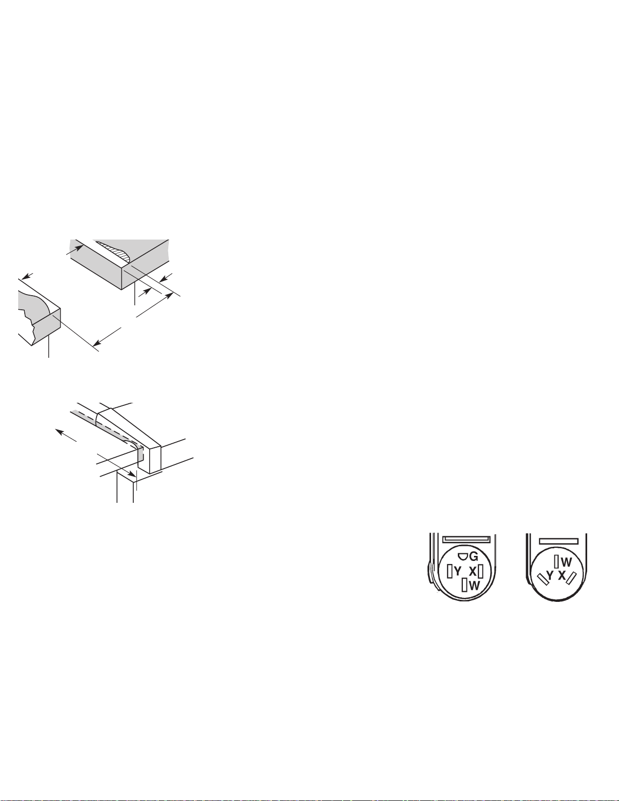
Slide-in ranges:
countertop
preparations
The cooktop sides of the slide-in range fit
over the cutout edge of your countertop.
If you have a square finish (flat)
countertop and the opening width is
30" (76.2 cm), no countertop preparation
is required.
Formed front-edged countertops: Must
have molded edge shaved flat 1/2" (1.3 cm)
from each front corner of opening.
Tile countertops may need trim cut back
1/2" (1.3 cm) from each front corner
and/or rounded edge flattened.
Formed or tiled
countertop trimmed
1/2" (1.3 cm) back at
front corners of
countertop opening.
30-7/8" (78.4 cm)
1/2"
(1.3 cm)
22-5/8"
(57.5 cm)
30"
(76.2 cm)
opening
width
Cooktop sides of
range fit over edges of
countertop opening.
If countertop opening width is greater
than 30" (76.2 cm), adjust the 1/2" (1.3
cm) dimension.
Countertop must be level. Place level on
countertop, first side to side; then front
to back. If countertop is not level, range
will not be level. Oven must be level for
satisfactory baking conditions.
Electrical requirements
If codes permit and a separate ground
wire is used, it is recommended that a
qualified electrician determine that the
ground path and wire gauge are in
accordance with local codes.
This range must be connected to a
grounded metal, permanent wiring
system.
Check with a qualified electrician if you
are not sure range is properly grounded.
Do not ground to a gas pipe.
Do not have a fuse in the neutral or
ground circuit.
Range must be connected to the proper
electrical voltage and frequency as
specified on the model/serial rating plate.
(The model/serial rating plate is located
on the oven frame behind the storage
drawer panel.)
A four-wire or three-wire, single-
phase, 120/240-volt, 60-Hz, AC-only,
electrical supply (or three-wire or fourwire 120/208-volt if specified on the
model/serial rating plate) is required on a
separate, 40 amp circuit, fused on both
sides of the line.
A time-delay fuse or circuit breaker is
recommended.
The range can be connected directly
to the fused disconnect (or circuit breaker
box) through flexible armored conduit.
This range can be direct wired to a fourwire or three-wire aluminum wiring
system. See “Direct wire method: Copper
or Aluminum wire” section.
Allow two to three feet of slack in the line
so that it can be moved if servicing is
ever necessary.
A U.L.-listed conduit connector must be
provided at each end of the power supply
cable (at the range and at the junction
box).
Wire sizes and connections must conform
with the rating of the range (40 amps).
The wiring diagram is located on the
back of the range or on the inside of the
storage drawer in a clear plastic bag.
Recommended ground method
It is the personal responsibility and
obligation of the customer to contact a
qualified electrician to assure that the
electrical installation is adequate and is in
conformance with the National Electrical
Code, ANSI/NFPA 70 — latest edition*
and all local codes and ordinances.
Power supply cord is not supplied, but is
available through your local electrical
supply house.
Copies of the standards listed may be obtained
from:
*National Fire Protection Association
One Batterymarch Park
Quincy, Massachusetts, 02269
If connecting to a four-wire
system:
This range is manufactured with the
ground connected to the cabinet. The
ground must be revised so the green
grounding wire of the four-wire power
supply cord is connected to the cabinet.
See “Four-wire electrical connection”
section.
When a four-wire receptacle of NEMA
Type 14-50R is used (see Figure 1, below),
a matching U.L.-listed, four-wire, 250-volt,
40 amp, range power supply cord (pigtail)
must be used. This cord contains four
copper conductors with either ring
terminals or spade terminals with
upturned ends to connect the power
supply at the appliance end, terminating
in a NEMA Type 14-50P plug on the
supply end. The fourth (grounding)
conductor must be identified by a green
or green/yellow cover and the neutral
conductor by a white cover. Cord should
be Type SRD or SRDT with a U.L.-listed
strain relief and be at least four feet long.
The minimum conductor sizes for the
copper four-wire power cord are:
40 amp circuit
2 No.-8 conductors
1 No.-10 white neutral
1 No.-8 green grounding
If connecting to a three-wire
system:
Local codes may permit the use of a
U.L.-listed, 250-volt, 40 amp range power
supply cord (pigtail). This cord contains
three, No.-10 copper wires and matches
a three-wire receptacle of NEMA Type
10-50R, shown in Figure 2. Connectors on
the appliance end must be provided at
the point the power supply cord enters
the appliance.
3-wire wall
receptacle (10-50R)
Figure 2
Figure 1
4-wire wall
receptacle (14-50R)
 Loading...