

Whirlpool EMZH3464 WS FH, EMZH3464 BR FH, AKF 803 AV, AKF 803/02, EMZH3463 IN User Manual
...
CONTENTS GB
INSTALLATION
ELECTRICAL CONNECTION
BEFORE USING THE APPLIANCES
PROTECTING THE ENVIRONMENT
PRECAUTIONS AND GENERAL
RECOMMENDATIONS
ENERGY SAVING TIPS
OVEN ACCESSORIES
COOKTOP ACCESSORIES
OVEN FUNCTIONS
PAGE
PAGE
PAGE
PAGE
PAGE
PAGE
PAGE
PAGE
PAGE
16
18
19
19
19
20
21
21
22
COOKTOP FUNCTIONS
CLEANING THE OVEN AND ITS ACCESSORIES
CARE AND MAINTENANCE OF CONVENTIONAL
ELECTRIC COOKTOPS
CARE AND MAINTENANCE OF
THE GLASS-CERAMIC COOKTOP
TROUBLESHOOTING GUIDE
AFTER SALES SERVICE
DECLARATION OF CONFORMITY CE
PAGE
PAGE
PAGE
PAGE
PAGE
PAGE
PAGE
23
23
25
25
25
26
26
15
INSTALLATION
Technical information for the installer
OVEN
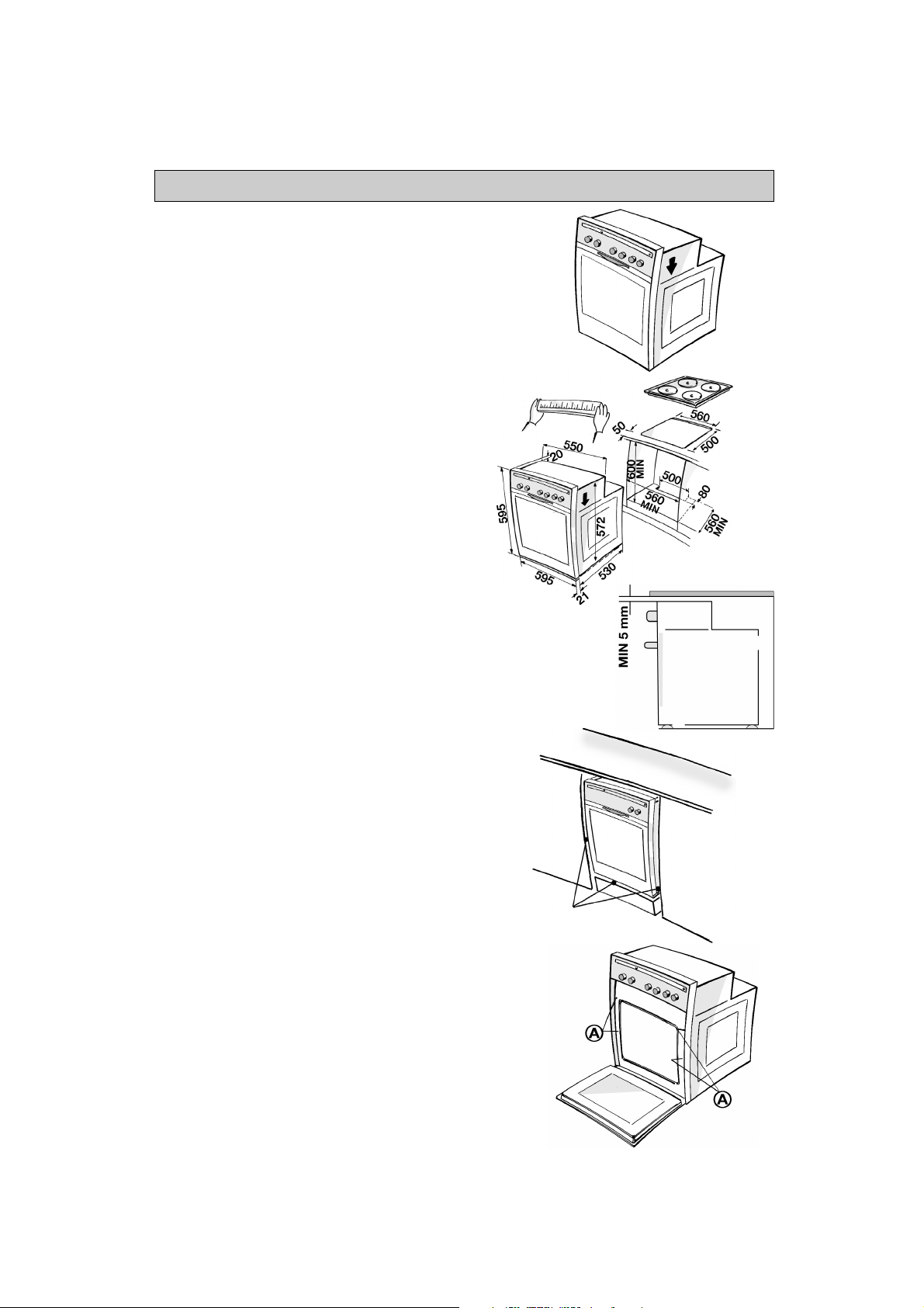
After removing the oven from its packaging, before
•
making the connections place it on the polystyrene
foam base to protect it from damage.
Do not attempt to lift the oven by the handle.
•
Lift at the sides as shown in the figure (see arrow).
Check that the appliance has not been damaged in
•
transit.
Oven dimensions and kitchen unit dimensions are
•
shown in the figure opposite.
Kitchen units in contact with the oven must be heat
•
resistant (80°C).
If plastic laminates or cement are not sufficiently
•
heat-resistant, warping, bubbling or detachment of
the finish may result.
Install the oven in the housing, lifting it at the sides,
•
taking care not to trap the wires of the electrical
supply cable.
For correct ventilation, follow the ventilation
•
opening directions shown in the figure
(500 x 80 mm min). An additional opening of 5 mm
is required between the oven top rim and the
cooktop lower rim: this opening must not be closed
by strips or housing crosspieces.
During oven installation, care must be taken to
•
ensure that the sides are not touching the front
edges of the housing or adjacent drawers and
doors (see picture).
Carry out the electrical connections between
•
cooktop and oven (see “Electrical connection”).
Secure the oven to the kitchen unit with screws (A)
•
as shown.
16
No Contacts
INSTALLATION
Cooktop
• The cooktop must be set into a worktop
between 20 mm and 50 mm thick.
There must be nothing between the cooktop
and the oven (cross rails, brackets, etc.).
• If the cooktop is to be installed next to a
column unit, leave a distance of at least 100
mm from the edge of the cooktop to the side of
the column unit.
•
Cut an opening in the worktop of the dimensions
shown in the Product Description Sheet supplied
separately.
•
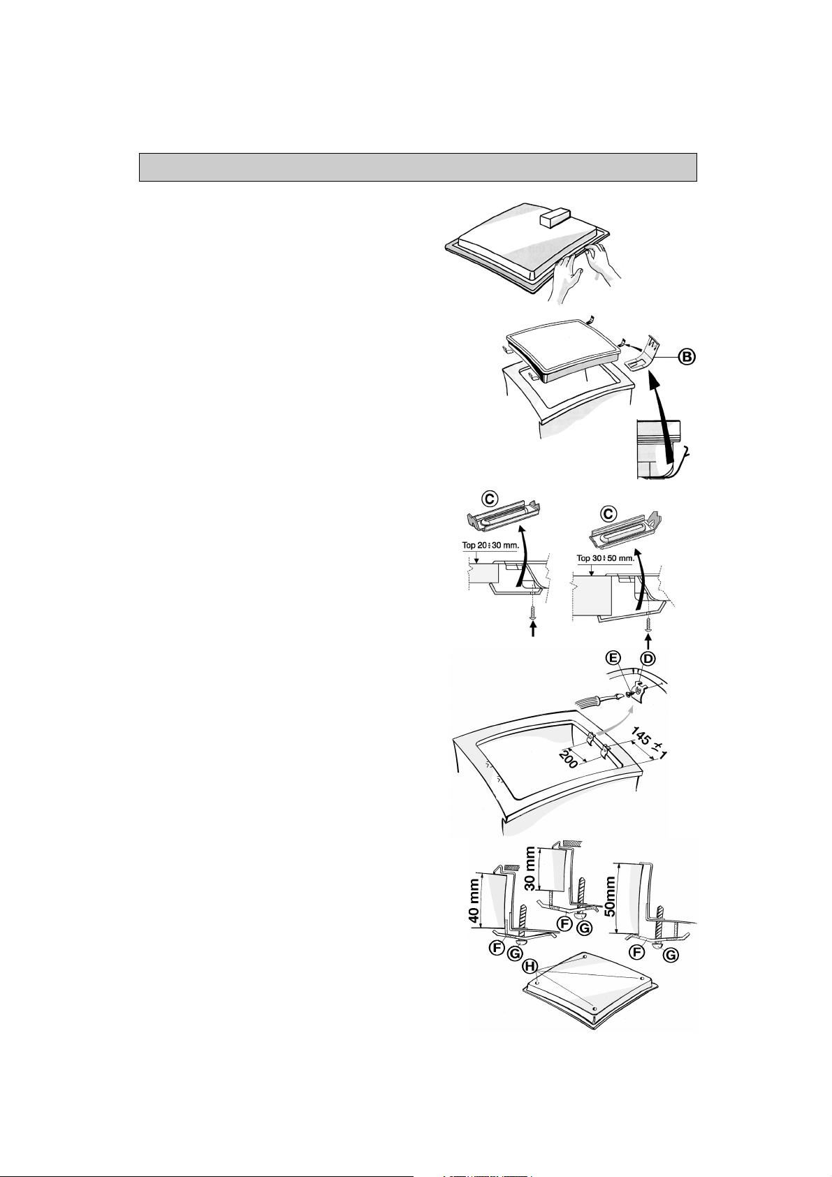
If not already present, fit the supplied seal to the
cooktop flange after cleaning the contact area as
shown in the top figure.
Cooktop with electric hotplates
• If the worktop is made of wood, fit the supplied
clips.
1.
Position the 4 spring clips (B) and fit them in their
locations on the underside of the cooktop.
2.
Fit the cooktop into the worktop.
• If the worktop is made of marble, plastic,
ceramics, natural stone, etc.,
must be secured with brackets (C) code
4819 310 18528 (to be requested from After Sales
Service).
1.
Position the brackets over the holes and secure
them with the supplied screws.
2.
Fit the cooktop into the worktop.
Glass-ceramic cooktop
N.B.:
Remove the protective film before installing the
cooktop.
• If the worktop is made of wood
spring clips and screws.
1.
Position the 4 clips (D) as shown and at the
specified dimensions.
2.
Secure the clips using screws (E).
3.
Fit the cooktop into the worktop.
• If the worktop is made of marble, plastic,
ceramics, natural stone, etc.
be secured with brackets (F) code 4819 404 78697
(to be requested from After Sales Service).
1.
Fit the cooktop into the worktop.
2.
Position the 4 brackets (F) as shown in the figure,
in accordance with the thickness of the worktop.
3.
Fix the 4 screws (G) in holes (H).
the cooktop
, use the supplied
, the cooktop must
17
ELECTRICAL CONNECTION
• Make sure the appliance is installed and
connected to the electricity supply by a
qualified technician in accordance with
the manufacturer's instructions and in
compliance with local regulations.
• The installer is responsible for the correct
electrical connection of the appliances
and the observance of the relative safety
recommendations.
Connecting the oven to the power supply
•
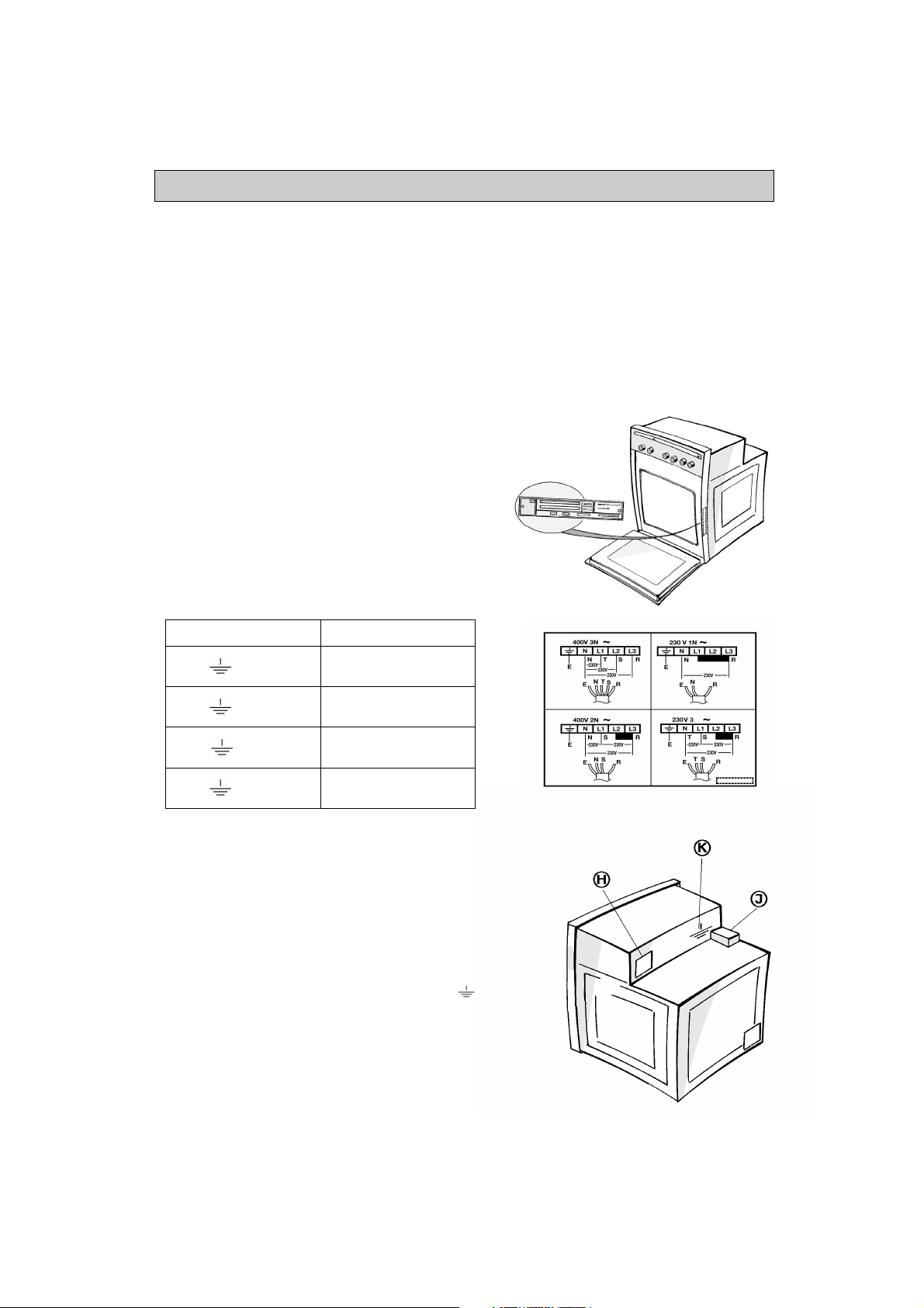
Make sure that the voltage shown on the rating
plate is the same as the power supply voltage in
your home. The service number is located on the
front edge of the oven cavity (visible when the
oven door is open).
•
Use a type H05RR-F power cord (minum length:
800 mm).
• Warning: All the oven's components operate at
230-240V. When using a 400 V connection,
make sure that the voltage reaching the oven is
230-240V, as illustrated in the side table.
Conductors X number Electrical connection
1N+
~
H05 RR-F 3X4 mmq
• The appliance must be connected to the
electricity supply by means of an all-pole
disconnect switch with minimum contact
gap of 3 mm.
• The appliances must be earthed by law.
• Do not use multiple plug adapters or
extension leads.
• After the oven has been installed, the
electrical components must be
concealed.
2N+
3+
3N+
~
~
~
H05 RR-F 4X2.5 mmq
H05 RR-F 4X2.5 mmq
H05 RR-F 5X1.5 mmq
Interconnecting cooktop and oven
•
Before connecting the oven to the power supply,
check that the cooktop is among the ones listed in
the cooktop/oven pairing product sheet.
•
Connect the 3 pole and 4 pole connectors to the
respective connectors on the oven.
The 3 pole connectors (H) is located at the rear
right hand side of the control panel, the 4 pole
connector (J) is located at the top of the oven in the
left hand corner (see figure).
•
Connect the yellow/green striped earth wire ( )
(K) from the cooktop to the screw located near the
3 pole connector.
WARNING: DO NOT CONNECT TO THE
POWER SUPPLY BEFORE YOU HAVE
FINISHED CONNECTING THE OVEN AND
THE COOKTOP.
•
Mount the oven in the kitchen unit.
Make sure the power cord is not entrapped.
18
 Loading...