

Whirlpool AGB 420/WP, AGB 422/WP, AGB 424/WP, AGB 410/WP, AGB 414/WP INSTRUCTION FOR USE
...Page 1

043_03
Installation, operating and
maintenance instructions
11/2005
GASFRY-PAN
APPLIANCES WITH ELECTRIC VALVES
AGB 404/WP · AGB 406/WP
AGB 408/WP · AGB 410/WP
AGB 412/WP · AGB 414/WP
AGB 418/WP · AGB 420/WP
AGB 422/WP · AGB 424/WP
AGB 426/WP · AGB 428/WP
AGB 416/WP · AGB 430/WP
Page 2

Models and dimensions page 3
Data of appliances 5
Technical data 5-6
Operating instructions 7
Construction, equipment installed
and safety devices 7
Assembly 7
Location 7
Legal and technical requisites 7
Installation 7
Installation procedure 7
Gas connection 7
Gas venting 7
Electrical connection 7
Equipotential 8
Commissioning the appliance 8
Before commissioning the appliance 8
Start-up 8
Testing the power rating 8
Checking input pressure 8
Checking power rating using
the volumetric method 8
Checking power rating when using
LP gas 8
Checking the pilot light 8
Checking the primary air 8
Checking the functions 9
Note for the installer page 9
Running the appliance on other types
of gas 9
Replacing the main burner nozzle 9
Adjusting the pilot burner 9
Maintenance 9
Replacing parts 9
Gas electrovalve 9
Burner 9
Thermocouple 9
Using the appliance 10
Preparation for use 10
Turning on and off 10
Lighting the pilot burner 10
Lighting the main burner 10
Extinguishing the main burner 10
Filling the tank.
Using the water loading knob 10
Special precautions 10
Emptying the tank 11
Turning off in an emergency 11
What to do in the case of malfunctioning
or if the appliance is not to be used for a
long period 11
Taking care of the appliance -
frequency of maintenance 11
WEEE Directive 12
Wiring diagram 13-14
Warning 15
INDEX
043-03 - Gasfry-pan
2
Page 3
043-03 - Gasfry-pan
3
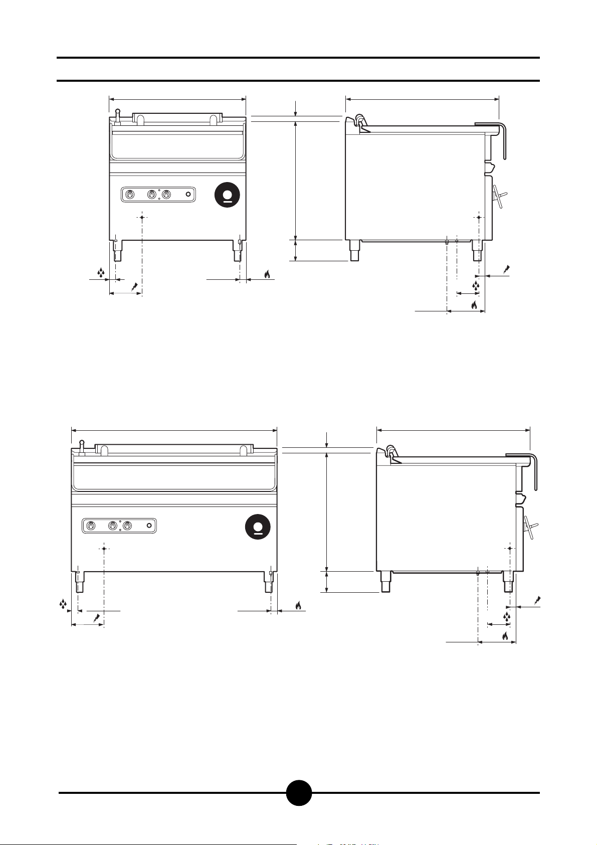
Dimensions
35
170
800
3/4"GC 25
AGB 404/WP - AGB 418/WP
AGB 406/WP - AGB 420/WP
30
140 10 770
900
3/4" GC
40
125
200
170
35
1200
30
140 10 770
3/4"GC 25
AGB 412/WP - AGB 426/WP
AGB 414/WP - AGB 428/WP
900
3/4" GC
40
125
200
Page 4
043-03 - Gasfry-pan
4
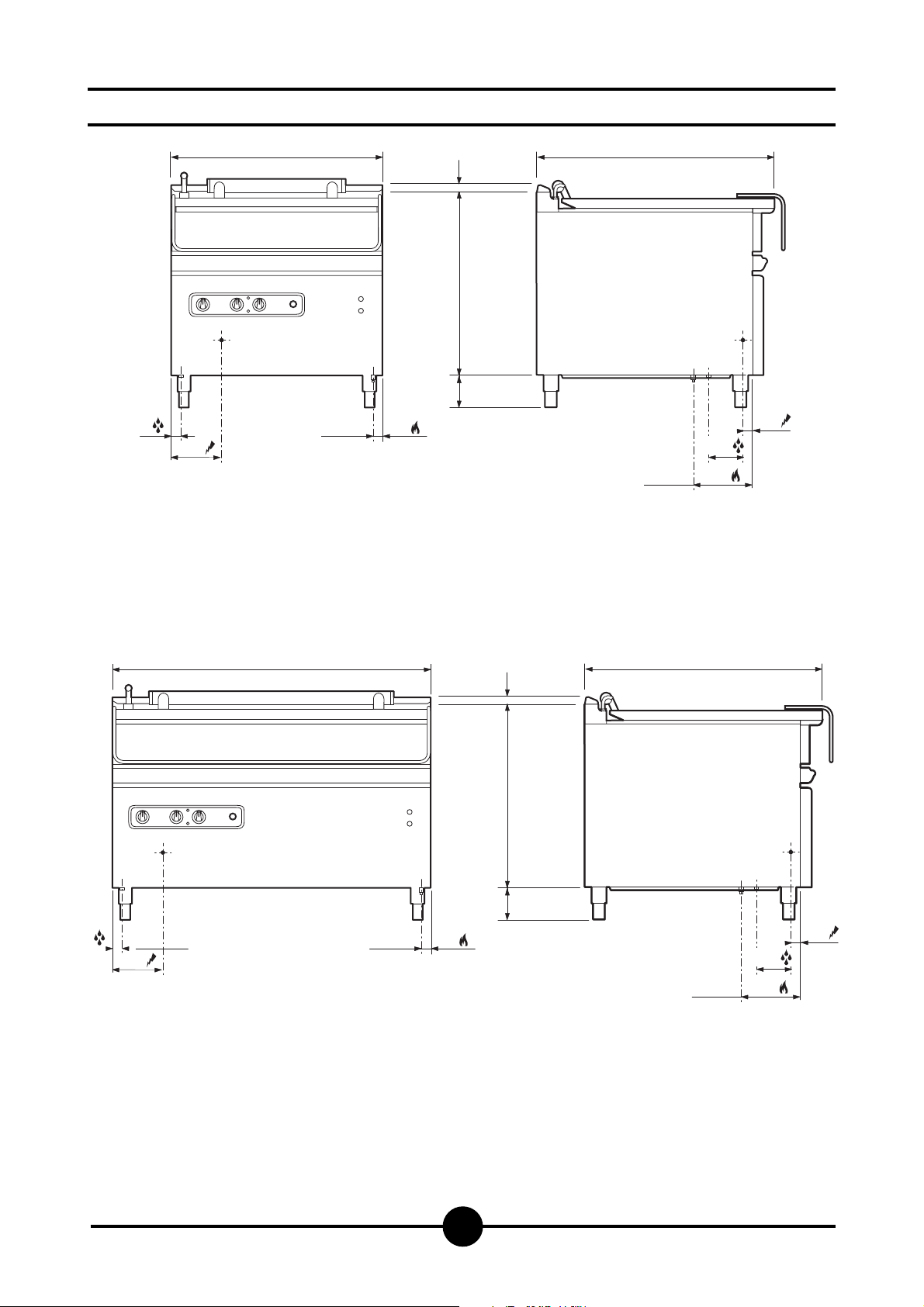
Dimensions
35
170
800
30
140 10 770
3/4"GC 25
AGB 408/WP - AGB 422/WP
AGB 410/WP - AGB 424/WP
900
3/4" GC
40
125
200
170
35
1200
30
140 10 770
3/4"GC 25
AGB 416/WP - AGB 430/WP
900
3/4" GC
40
125
200
Page 5
043-03 - Gasfry-pan
5
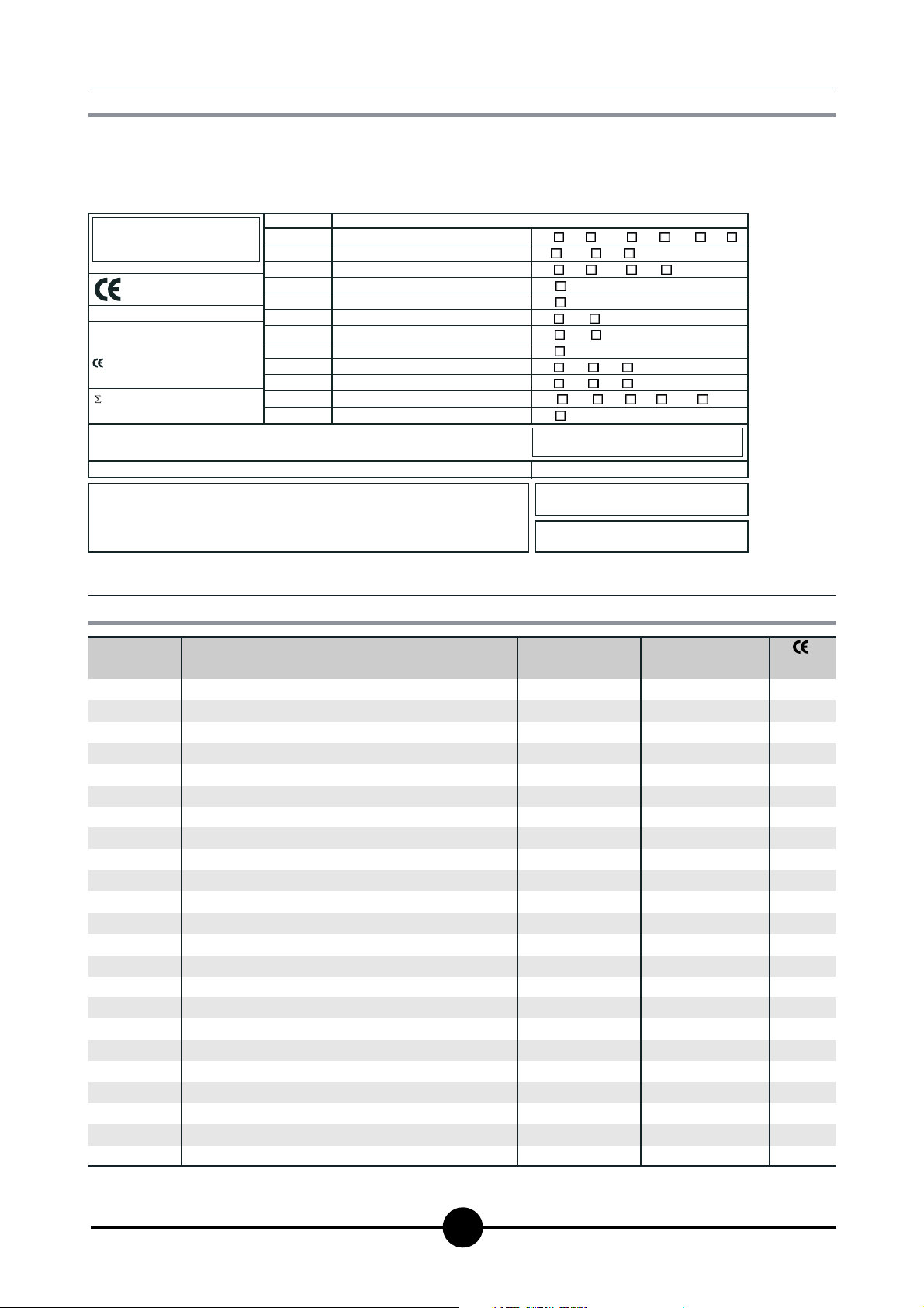
2 - DATA OF APPLIANCES
The instructions contained in this manual apply to our frypans in the II2H3+ category (see table on page 6).
The data plate is located on the front of the appliance and
CAT/KAT GAS/GAZ G30 G31 G20 G25
II2H3B/P P mbar 30 30 20 -
II2H3+ P mbar 30 37 20--
II2H3+ P mbar 28 37 20 -
0051
TIPO/TYPE
MOD.
ART.
N.
N.
Qn kW
MOD.
V AC kW Hz
THE APPLIANCE MUST BE CONNECTED IN COMPLIANCE WITH THE LAWS IN FORCE
AND INSTALLED IN A WELL-VENTILATED ROOM. READ THE INSTRUCTION MANUALS
BEFORE INSTALLING AND USING THE APPLIANCE.
THE APPLIANCE MUST BE INSTALLED BY QUALIFIED PERSONNEL.
m3/h
II2ELL3B/P P mbar 50 50 20 20
II2E+3+ P mbar 28 37 20 25
II2H3B/P P mbar 50 50 20 -
I2E P mbar - - 20 -
--II2H3B/P P mbar 30 30
II2H3+ P mbar 28 37 20 -
I3B/P P mbar 30 30
I3+ P mbar 28 37
Predisposto a gas: - Gas preset: - Prevu pour gaz:
Eingestelt für Gas: - Preparado para gas: -
--
--
Geschuckt voor:
on the control panel. It contains all necessary reference
data such as the name of the manufacturer, input pressure, gas type setting, etc.
SE FI DK CZ SK SI
IT CH PT
ES IE GB GR
NL
25II2L3B/P P mbar 30 30
DE
FR BE
AT CH
LU
EE LV LT
EE LV LT
NO MT CY IS HU
CY
MADE IN ITALY
G30/G31 28/37 mbar
G20 20 mbar
Model
AGB 404/WP
AGB 406/WP
AGB 408/WP
AGB 410/WP
AGB 412/WP
AGB 414/WP
AGB 416/WP
AGB 418/WP
AGB 420/WP
AGB 422/WP
AGB 424/WP
AGB 426/WP
AGB 428/WP
AGB 430/WP
3 - TECHNICAL DATA
Description
Gas tilting bratt pan
Gas tilting bratt pan - stainless steel tank
Gas tilting bratt pan - automatic lifting
Gas tilting bratt pan - automatic lifting - stainless steel tank
as tilting bratt pan
Gas tilting bratt pan - stainless steel tank
Gas tilting bratt pan - automatic lifting
Gas tilting bratt pan - automatic lifting - stainless steel tank
Dimensions
(LxPxH)
800 x 900 x 875
800 x 900 x 875
800 x 900 x 875
800 x 900 x 875
1200 x 900 x 875
1200 x 900 x 875
1200 x 900 x 875
1200 x 900 x 875
800 x 900 x 530
800 x 900 x 530
800 x 900 x530
800 x 900 x 530
1200 x 900 x 530
1200 x 900 x 530
1200 x 900 x 530
1200 x 900 x 530
Tank dimension
(Capacity)
720 x 620 x 190 (84)
720 x 620 x 190 (84)
720 x 620 x 190 (84)
720 x 620 x 190 (84)
1120 x 620 x 190 (126)
1120 x 620 x 190 (126)
1120 x 620 x 190 (126)
1120 x 620 x 190 (126)
720 x 620 x 190 (84)
720 x 620 x 190 (84)
720 x 620 x 190 (84)
720 x 620 x 190 (84)
1120 x 620 x 190 (126)
1120 x 620 x 190 (126)
1120 x 620 x 190 (126)
1120 x 620 x 190 (126)
N.
51BQ2894
51BQ2894
51BQ2894
51BQ2894
51BQ2893
51BQ2893
51BQ2893
51BQ2894
51BQ2894
51BQ2894
51BQ2894
51BQ2893
51BQ2893
51BQ2893
Page 6

043-03 - Gasfry-pan
6
Model
Category
Construction type
Air necessary for combustion
Nominal capacity
Minimum capacity
Overall capacity (Gas)
AGB 404/WP
AGB 406/WP
AGB 408/WP
AGB 410/WP
AGB 412/WP
AGB 414/WP
AGB 416/WP
AGB 418/WP
AGB 420/WP
AGB 422/WP
AGB 424/WP
AGB 426/WP
AGB 428/WP
AGB 430/WP
Input pressure
Natural gas 2H
LP gas 3+
G20
G30/G31
Gas connection values (consumption)
Natural gas 2H
LP gas 3+
(HuB = 9.45 kWh/m
(HuB = 12.87 kWh/kg) in kg/h
II2H3+
B
3
/h
m
kW
kW
20 mbar
28/37 mbar
3
) in m3/h
TABLE 1
AGB 404/WP - AGB 406/WP - AGB 408/WP
AGB 410/WP - AGB 418/WP - AGB 420/WP
AGB 422/WP - AGB 424/WP
38
19
-
19.0
kW
19.0
kW
19.0
kW
19.0
kW
19.0
kW
19.0
kW
19.0
kW
19.0
kW
2.01
0.54
AGB 412/WP - AGB 414/WP
AGB 416/WP - AGB 426/WP - AGB 428/WP
AGB 430/WP
57
27
-
27.0
kW
27.0
kW
27.0
kW
27.0
kW
27.0
kW
27.0
kW
27.0
kW
27.0
kW
2.86
0.72
Nozzles Ø 1/100 mm.
G20
Main
burner
G30/31
N. nozzles pilot burner
Primary air distance "A"
Electrotechnical data
Reference
-
Reference
-
G20
G30/G31
Gaz naturel G20
Gaz liquide G30/G31
Power :
0,05 kW
4 x 155
-
4 x 110
-
36
19
Fixe
Fixe
Voltage rating:
230 V AC 50 Hz
6 x 150R
-
6 x 10⁵R
-
2 x 36
2 x 19
Fixe
Fixe
Lead wire / Section:
(HAR) H07 RN F 3 x 1 mm
2
Page 7

043-03 - Gasfry-pan
7
Construction, equipment installed and
safety devices
Robust steel frame, with 4 legs (adjustable in height).
18/10 chrome-nickel steel outer panelling.
The tank is heated by stainless steel burners (4), resistant
to thermal stress and shock.
The pilot burner is fitted with fixed nozzles.
The combustion chamber and the flue pipes are in
electrogalvanised stainless steel plate.
The temperature is regulated by means of a thermostat,
which controls the ignition and turning off of the burners.
ASSEMBLY
Location
The appliance should be installed in a well ventilated
room, and if possible under a range hood.
The appliance can be installed on its own or alongside
other equipment.
If the appliance is to be installed near inflammable walls, a
minimum distance of 50 mm. around the sides and back
should be allowed.
Place table-top appliances on a table or shelf in flameproof material. Before connecting up the appliance to the
gas supply, check on the data plate that the appliance is
fitted for the type of gas available.
If not, consult paragraph “Running the appliance on other
types of gas”, page 9.
Legal and technical requisites
During assembly, the following legal and technical
requisites should be adhered to:
- relevant national legislation;
- local building and fire safety regulations;
- worksheet “Technical rules for installing gas”;
- worksheet “Technical rules for LP gas”;
- worksheet “Gas installations in industrial kitchens”;
- industrial injury legislation;
- local Gas Board regulations;
- current CEI regulations.
INSTALLATION
Assembly, installation and maintenance, i.e.: assembly,
connecting the gas supply, checking power rating, transforming or adapting the appliance to run on other types of
gas, and commissioning, must all be done by contractors
authorised by the local Gas Board in accordance with
local and national legislation. Before doing anything else,
seek advice from your Gas Board.
Installation procedure
To level the appliance correctly, adjust the height of the
four legs.
Gas connection
The R 3/4” gas off-take on the appliance can either be
permanently fixed to the mains or made detachable using
a standard gas tap.
If flexible hose is used, it must be in stainless steel and to
DIN 3383 part 1 or DIN 3384 standard.
After completing connection, check for leaks using a
special leak-detector spray.
Elimination of exhaust gas
The bratt pans with type B construction cannot operate
without a windproof device.
The exhaust gas connection should be carried out using
regulation pipes, in accordance with the procedures required by existing standards and any other regulations related to the location. The scavenging of the exhaust gases
should occur:
a) by natural ascension to the exterior through a chimney
b) by mechanical extraction through a chimney on the exterior or directly to the outside;
c) through suction hoods.
Electrical connection
Before connecting the appliance to the mains, check that:
- The mains voltage corresponds to the values on
therating plate;
- The appliance is properly earthed;
- The cable is suitable for the power input.
In addition a tripping device with a contact cutoff of at
least 3 mm must be placed between the appliance and
the mains socket so that omnipolar disconnection is
possible. Safety contactors, for example, may be used for
this purpose.
The omnipolar switch must be near the appliance and
easily accessible. The power cable must be approved
and have a suitable cross section for the appliance.
It should be at least the type H07 RN-F.
OPERATING INSTRUCTIONS
Mount the windproof device
as follows:
- Position the part (A) on the
appliance and fix using the
screws provided;
- Introduce the extension (B)
onto the header;
- Position the part (C ) on the
wall (A) and fix everything
using the self-tapping
screws;
- Mount the back (D) on the
part (A) and fasten.
DC
A
B
Page 8

043-03 - Gasfry-pan
8
Before commissioning the appliance
Before commissioning the appliance, remove the
protective wrapping.
Thoroughly clean the work-surface and the outside of the
appliance using lukewarm water and detergent.
With a damp cloth eliminate all traces of the rust-proofing
applied in the workshop then dry with a clean cloth.
Start-up
Before starting the appliance up, check that its
specifications (category and type of gas used) match
those of the family and group of the gas available locally.
If not, adapt the appliance to the gas family or group
required (see paragraph “Running the appliance on other
types of gas” page 9).
To start the appliance up, see the instructions for regular
use (see "Special precautions", page 10).
Testing the power rating
Use the specific nozzles for the rated output (see table 1 in
assembly instructions).
The following are the operating pressure tolerances to obtain the nominal power according to the agreed nozzles:
- from 15 to 22.5 mbar for gases of the second family;
- from 25 to 35 mbar for gases of the third family
(propane).
The appliance will not work outside the above pressure
thresholds.
If you wish to check the nominal capacity further, you may
do so using a gas meter according to the so-called
”volumetric method”.
As a rule, however, it is sufficient to check that the correct
nozzles are being used.
Checking input pressure (Fig. 1)
Input pressure should be measured using a gauge (e.g. a
gooseneck pipe, min. resolution 0.1 mbar).
Remove screw 19 from the pressure socket and connect
it to the tube on the gauge; after measuring, the screw
should be retightened absolutely airtight 19.
Checking power rating using the
volumetric method
Using a gas meter and a chronometer, you can read the
volume of gas output per time unit.
The correct volume will be the value of “E” expressed in
litres per hour (It/hr) or litres per minute (It/min).
The following formula is used to calculate the value of “E”:
Capacity should only be measured when the appliance is
at a standstill.
The heat value can be obtained from your local Gas
Board.
To obtain the nominal capacity in relation to the nominal
pressure, consult “TECHNICAL DATA” table.
Attention!
It is not possible to adjust nominal capacity in
advance.
Checking power rating when using LP
gas
Check that the type of nozzles used match manufacturer's
specifications.
Check that the pressure reducer installed on the
appliance has an outlet pressure in compliance with
paragraph "Testing the power rating", page 8 (see data
plate or measure the pressure).
Checking the pilot light
When correctly adjusted, the pilot light flame will
completely surround the thermocouple and will not flicke.
Checking the primary air
The appliances have no primary-air regulating device.
Capacity
Heat value
E =
COMMISSIONING THE APPLIANCE
1
Equipotential
The appliance must be connected to an equipotential
system. The relative terminal can be found at the rear of
the appliance near the cable inlet, marked by a label.
16
15
1
17320 13 18 21
19
Page 9

043-03 - Gasfry-pan
9
Checking the functions
- Start the appliance in accordance with the instructions;
- Check the gas tubes for leaks;
- Check that the flame on the main burner lights properly
and is correctly formed;
- Check that the pilot light is correctly regulated;
- Draw up a servicing and maintenance contract.
Note for the installer
- Explain and demonstrate to the user how the machine
works according to the instructions and hand him this
manual.
- Remind the user that any structural alterations to the room
housing the appliance may affect the combustion air
supply. Once the alterations have been completed, the
appliance and its functions should be thoroughly
checked.
Running the appliance on other types of
gas
When changing to another type of gas, e.g. from natural to
LP, or to another gas group, consult the “TECHNICAL DATA”
table to determine the correct nozzles to use.
The nozzles for the main burners for different types of gas,
marked in 100ths of mm, are in a case supplied with the
appliance. When the appliance has been transformed or
adapted, recheck its functions as described in paragraph
"Checking the functions", page 9.
Replacing the pilot burner nozzle
(Fig. 2)
To change nozzle 30, loosen the fixing screws of the front
instrument panel. Remove the panel.
Using a No. 12 wrench, unscrew the nozzle from the nozzle
holder; replace with a new nozzle (see “TECHNICAL DATA”
table).
Replacing the pilot burner nozzle
(Fig. 2)
The pilot burner is readily accessible once the front panel
has been removed (as described above).
The pilot burner has a fixed gas supply.
To change to another type of gas, replace the nozzle on
burner 36 according to the type of gas used, by loosening
hose 35 (see “TECHNICAL DATA” table).
MAINTENANCE
Attention!
Before carrying out any maintenance or repair work,
disconnect the appliance from the mains.
The following maintenance programme should be carried
out at least once a year:
- Check that all the safety and setting devices are working
properly;
- Check that the burners are working properly with regard
to:
- ignition
- combustion safety;
- Check the functions of the appliance as described in
paragraph "Checking the functions", page 9;
- Check the gas venting path (make sure the gas is
correctly evacuated).
REPLACING PARTS
All parts must be replaced by authorised technicians
only!
To replace the following parts, remove the control panel
(after unscrewing its fixing screws). It is advisable to empty
the tank.
Gas electrovalve (1 - Fig. 1)
Unscrew the fitting (3, 16, 21, 17) and loosen the fixing
screws. The valve may now be removed and replaced with a
new one. Replace and screw down all parts in the correct
order.
Burner (31 - Fig. 2)
Unscrew the nut 29 and remove the nozzle-holder 28.
Loosen the screw fixing the burner to the chamber Replace
the burner.
Thermocouple (38 - Fig. 2)
Unscrew the nipple fixing the thermocouple to the valve,
loosen the 2 screws on the pilot burner and replace the
thermocouple. To simplify the operation (and all those
concerning the pilot burner), screws may be removed and
the pilot burner moved to a more accessible position.
2
37
38
29
30
31
34
36
35
28
Page 10

Attention!
- Beware of inexpert handling!
- The main burner only ignites if the tank is
positioned correctly on the heating chamber.
Preparation for use
Before frying for the first time, it is advisable to thoroughly
clean the appliance and above all the tank (see
paragraph "Taking care of the appliance frequency of
maintenance", page 11).
Turning on and off (Fig. 3)
Turn on gas supply.
Lighting the pilot burner
Put the main switch 40 to on. Press and turn the knob 13
clockwise to the spark position : in this way ignition is
enabled until the pilot flame lights. The pilot flame can be
seen through the relative hole.
Lighting the main burner
To light the main burner, turn the knob 13 clockwise once
more as far as the flame symbol and place knob 2 to
the required temperature. A yellow light comes on when
the burners are lit.
Extinguishing the main burner
To turn off just the main burner, turn the knob 13 to the
spark position and/or place knob 2 to position zero;
in this way only the pilot burner remains lit. To extinguish
both burners, turn the knob 13 counter-clockwise and the
on-off switch to the off position; in this way the pilot burner
is also extinguished.
Filling the tank.
Using the water loading knob
The appliance is fitted with a water loading cock consisting
of an open/close control knob 50 and a curved spout. When
the tank lid is open, turn knob 50 to the open position.
Attention!
Do not open the cock if the tank is not in the correct
operating position.
Never overfill the tank.
Special precautions
The grills, particularly those with the pan bottom not in
stainless steel, are treated in the factory with mineral oil to
protect them from rust.
The oil should be carefully removed before heating the
pan, using hot water and detergent, not chlorine based
(less than 30 ppm). After washing, rinse with cold water
and heat to 300°C to dry, with the thermostat at the maximum . When the thermostat shuts down, the oven is ready
for cooking or, after protecting the bottom with a layer of
grease or cooking oil, ready to rest (after use). After every
use, especially when the pan is not in stainless steel, to
keep it in perfect condition and protect it from rust, repeat
the above operation of washing, drying and protecting
with grease or cooking oil.
If any rust should form on the bottom of the pan due to water or moisture and lack of adequate protection after use,
it will continue to expand until it corrodes the pan. If this
should occur, the rust must be removed until the corroded
part is polished, using a pad of steel wool, for example, in
stainless steel and then washing, drying and protecting
as described above.
NOTE: Greasing or oiling the pan while still damp is
not only useless but absolutely dangerous as the rust
will continue to expand under the layer of grease.
USING THE APPLIANCE
043-03 - Gasfry-pan
10
4
0
5
3
0
0
2
5
0
2
0
0
0
1
0
5
1
0
50 2 40 13
Page 11

043-03 - Gasfry-pan
11
Emptying the tank
The appliance is fitted with a tilting tank; to facilitate emptying and cleaning operations, the tank can be overturned
using a handle for the AGB 404/WP - AGB 406/WP AGB 412/WP - AGB 414/WP - AGB 418/WP - AGB 420/WP
- AGB 426/WP - AGB 428/WP versions, or two buttons (red
for “up” and black for “down”) in the AGB 408/WP AGB 410/WP - AGB 416/WP - AGB 422/WP - AGB 424/WP
- AGB 430/WP. motorized versions.
Attention!
This operation should be carried out when the tank is
cold, making sure that:
- a large capacity container is placed at the foot of the
tank (under the drainage outlet);
- the tank is tipped upside down very slowly so that
all its contents exit from the drainage outlet without
spillage, which could create a hazard;
- the speed is constant to avoid jolts which could
make the contents undulate.
Turning off in an emergency
In the case of malfunctioning, turn off the appliance as
described in paragraph "Turning on and off", and turn off
the gas supply.
What to do in the case of
malfunctioning or if the appliance is
not to be used for a long period
When the appliance is not to be used for a long time,
clean thoroughly and turn off the gas supply.
In the case of malfunctioning or failure, turn off the gas
supply and disconnect from the mains. Call the service
centre.
TAKING CARE OF THE APPLIANCE
FREQUENCY OF MAINTENANCE
Attention!
Never clean the appliance with jets of water, whether
direct or pressurised.
Allow the machine to cool down before cleaning
Giving the appliance a thorough clean every day (after
turning it off) will keep it in perfect working order and make
it last longer.
All steel parts should be cleaned with water and a
detergent, using a damp cloth; do not use abrasive
substances or corroding detergents.
Do not use steel wool, which could leave traces of rust.
For the same reason, avoid touching the appliance with
anything made of iron.
Do not clean any parts of the appliance other than the
grilling plate with emery or sandpaper. If absolutely
necessary, you may use powdered pumice stone.
If the appliance is extremely dirty, use a synthetic sponge
such as Scotchbrite.
After cleaning the appliance, rinse with clean water and
dry with a clean cloth.
To make cleaning easier is possible to installed a tilting
tank.
All maintenance work must be carried out by qualified
personnel only.
Have the appliance checked at least once a year; we
strongly recommend that you stipulate a servicing and
maintenance contract with your supplier.
Warning!
- The first time you use the pan, wash it with soap and
water.
- Never use synthetic cloth to clean, only cotton, wool
or linen
- Never fill the bottom of the pan with grease
- Do not fill the pan with oil; it cannot be used for frying
because of the fire hazard represented by the oil .
Page 12

THE 2002/96/EC DIRECTIVE (WEEE):
information to users
This informational note is meant only for owners
of equipment marked with the symbol shown in
Fig. A on the adhesive label featuring the technical specifications applied on the actual product
(the label also giving the serial number).
This symbol indicates that the product is classified, according to the regulations in force, as an item of electrical
and electronic equipment and conforms to EU Directive
2002/96/EC (WEEE) meaning that, at the end of its service
life, it must be treated separately from domestic waste, i.e.
it must be handed in free of charge to a separate waste
electrical and electronic equipment collection centre or
returned to the reseller when buying a new equivalent item
of equipment.
The user is responsible for delivering the unit at the end of
its life to the appropriate collection facilities. Failure to do
so shall result in the user being subject to the penalties
prescribed by the legislation in force on waste.
Suitable separated collection so that the unit no longer
used can be sent off for environmentally compatible recycling, treatment and disposal helps avoid possible negative effects on the environment and on health and facilitates
the recycling of the product's component materials.
For more detailed information on available collection systems, contact the local waste disposal service or the
shop you purchased the unit from.
Producers and importers fulfil their responsibility for environmentally compatible recycling, treatment and disposal
both directly and by joining a collective scheme.
043-03 - Gasfry-pan
12
Page 13

043-03 - Gasfry-pan
13
Wiring diagrams
F2
21
F2
11
S1
21
11
S1
H1
AGB 404/WP - AGB 418/WP
S2
AGB 406/WP - AGB 420/WP
21
F1
11
H2
S1
H1
AGB 412/WP - AGB 426/WP
AGB 414/WP - AGB 428/WP
mA
Line input terminal board
S1
Gas electrovalve
B1
Luminos switch
F1
Thermostat
F2
Safety thermostat
H1
Green pilot lamp
Yellow pilot lamp
H2
HT transformer
Z1
S2
Pilot safety valve
1
B1
P1 P2
mA
l1 N T
230/1 AC
2
Page 14

043-03 - Gasfry-pan
14
F2
y
Wiring diagrams
21
F2
11
S1
21
11
S1
H1
AGB 408/WP - AGB 422/WP
S2
AGB 416/WP - AGB 430/WP
AGB 410/WP - AGB 424/WP
21
F1
11
H2
NC
M1
C
NC
NC
C
M2
NC
1
B1
2
P1 P2
S1
Pu1
Pu2
213
2
1
H1
4
3
4
M
W2
U4
W1V1U1
V2
mA
Line input terminal board
S1
Gas electrovalve
B1
Luminos switch
F1
Thermostat
F2
Safety thermostat
M1
Up micro
M2
Down micro
H1
Green pilot lamp
H2
Yellow pilot lamp
Pu1
Up button
Pu2
Up button
Z1
HT transformer
S2
Pilot safet
mA
l1 N T
230/1 AC
valve
Page 15

WARNING
DUE TO ITS POLICY OF CONTINUAL PRODUCT IMPROVEMENT, THE MANUFACTURER RESERVES THE RIGHT
TO MAKE ANY CHANGES DEEMED NECESSARY.
THE MANUFACTURER CANNOT BE HELD RESPONSIBLE IF THE INSTRUCTIONS CONTAINED IN THIS MANUAL ARE NOT OBSERVED.
043-03 - Gasfry-pan
15
WHIRLPOOL EUROPE srl
V.le Guido Borghi, 27
I – 21025 Comerio – VA
 Loading...