


016_03
Installation, operating and
maintenance instructions
02/2006
ELECTRIC COOKERS
AGB 355/WP
AGB 364/WP · AGB 365/WP
AGB 366/WP · AGB 367/WP

016-03 - Electric cookers
2
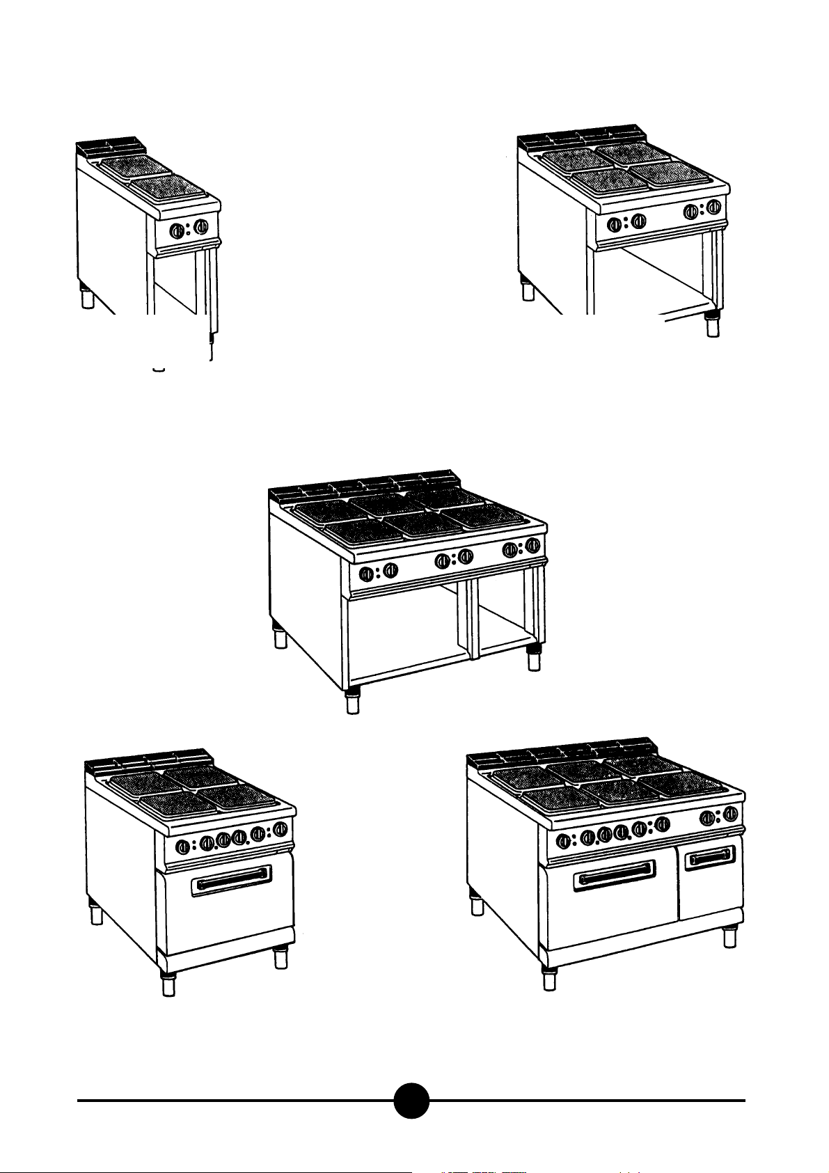
Models and dimensions page 3
Technical data 5
Installation instructions 6
Installation 6
Legal and technical requisites 6
Installation 6
Wiring 6
Unipotential 6
Using the appliance 6
Ignition 6
Cleaning and taking care of the
appliance 7
What to do if not using the appliance
for a long time 7
What to do if something goes wrong 7
Maintenance 7
WEEE Directive 8
Wiring diagrams 9-17
Warning 18
INDEX
016-03 - Electric cookers
3
AGB 364/WP
400 x 900 x 275
Weight approx.52 kg
AGB 365/WP
800 x 900 x 275
Weight approx.96 kg
AGB 355/WP
800 x 900 x 275
Weight approx.138 kg
Dimensions
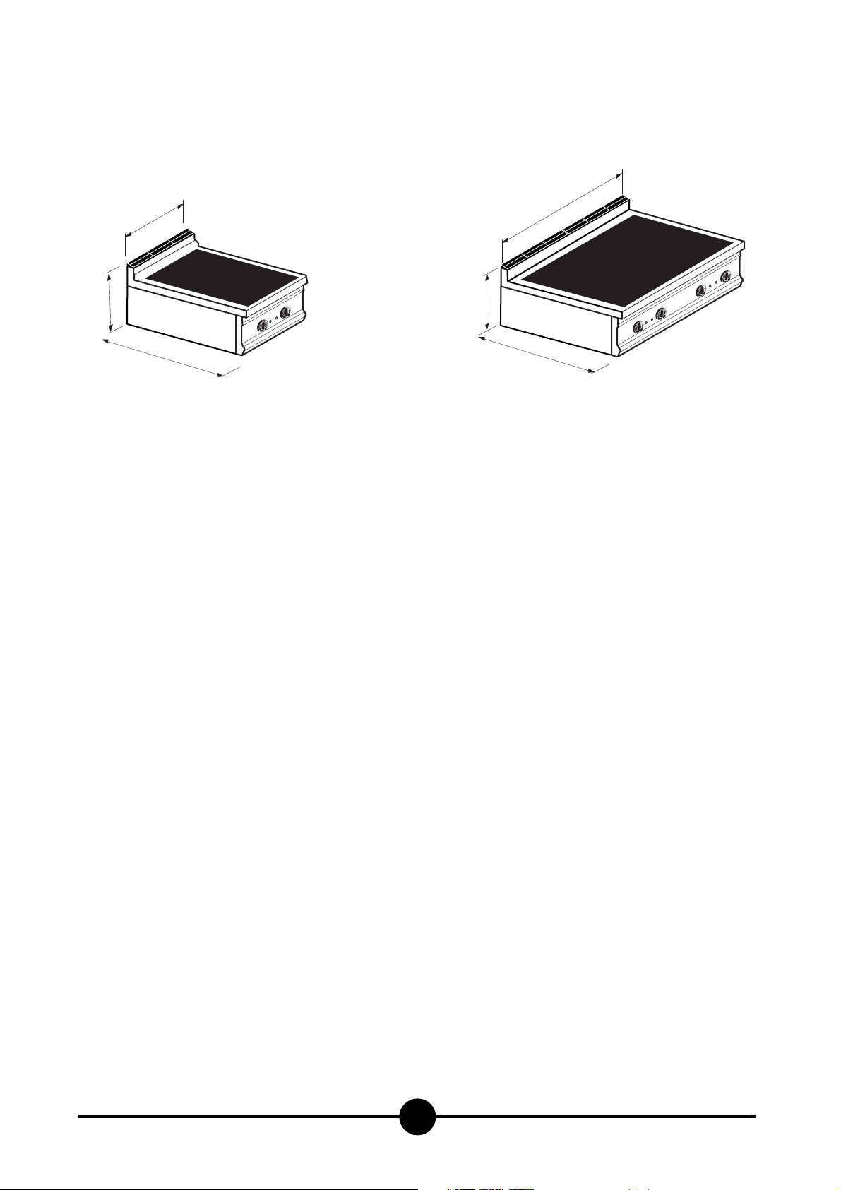
Dimensions
016-03 - Electric cookers
4
400
270
900
AGB 366/WP
Weight approx.52 kg
800
270
900
AGB 367/WP
Weight approx.92 kg
016-03 - Electric cookers
5
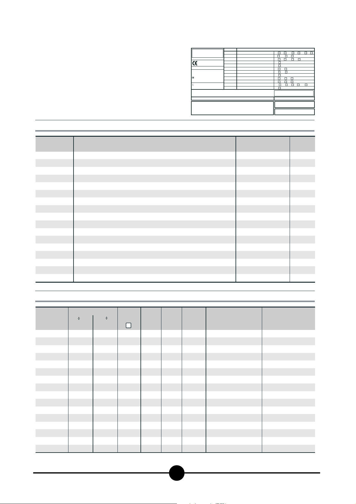
The data plate is located on the rigth hand side of the
control panel and contains all the data needed for connecting
it up to the mains electricity supply.
3 - TECHNICAL DATA
CAT/KAT GAS/GAZ G30 G31 G20 G25
II2H3B/P P mbar 30 30 20 -
II2H3+ P mbar 30 37 20--
II2H3+ P mbar 28 37 20 -
0051
TIPO/TYPE
MOD.
ART.
N.
N.
Qn kW
MOD.
V AC kW Hz
THE APPLIANCE MUST BE CONNECTED IN COMPLIANCE WITH THE LAWS IN FORCE
AND INSTALLED IN A WELL-VENTILATED ROOM. READ THE INSTRUCTION MANUALS
BEFORE INSTALLING AND USING THE APPLIANCE.
THE APPLIANCE MUST BE INSTALLED BY QUALIFIED PERSONNEL.
II2ELL3B/P P mbar 50 50 20 20
II2E+3+ P mbar 28 37 20 25
II2H3B/P P mbar 50 50 20 -
I2E P mbar - - 20 -
II2H3+ P mbar 28 37 20 -
I3B/P P mbar 30 30
m3/h
I3+ P mbar 28 37
Predisposto a gas: - Gas preset: - Prevu pour gaz:
Eingestelt für Gas: - Preparado para gas: -
--II2H3B/P P mbar 30 30
--
--
Geschuckt voor:
SE FI DK CZ SK SI
IT CH PT
ES IE GB GR
NL
25II2L3B/P P mbar 30 30
DE
FR BE
AT CH
LU
EE LV LT
EE LV LT
NO MT CY IS HU
CY
MADE IN ITALY
Model
AGB 355/WP
AGB 364/WP
AGB 365/WP
AGB 366/WP
AGB 367/WP
Model
AGB 355/WP
AGB 364/WP
AGB 365/WP
AGB 366/WP
AGB 367/WP
Version
Electric range - 2 plates on open stand
Electric range - 4 plates on open stand
Electric range - 6 plates on open stand
Electric range 4 plates - electric convection oven 1/1 GN
Electric range 4 plates - electric oven 2/1 GN
Electric range 6 plates - 1/1 GN electric convection oven - neutral unit
Electric range 6 square plates - 2/1 GN electric oven - neutral unit
Electric pyroceramic range with 2 plates - neutral unit
Electric pyroceramic range with 4 plates - neutral unit
Electric pyroceram range 4 plates - electric 1/1 GN convection oven
Electric pyroceram range 4 plates - 2/1 GN electric oven
Electric range - 2 plates
Electric range - 4 plates
Electric range - 6 plates
Electric pyroceramic range with 2 plates
Electric pyroceramic range with 4 plates
TABLE 1
Resistance (kW) Voltage rating
1 2.5
1.5 3.4
Plates
4 kW
Oven
2.5 kW
Oven
5.9 kW
-
-
-
-
-
-
-
-
1
2
2
2
-
-
-
1
2
-
-
-
-
-
-
-
1
2
2
2
-
-
-
1
2
2
4
6
4
4
6
6
-
-
-
-
2
4
6
-
-
-
-
-
1
-
1
-
-
-
1
-
-
-
-
-
-
Power
-
-
8.0 kW
-
16.0 kW
-
24.0 kW
-
18.5 kW
1
21.9 kW
-
26.5 kW
1
29.9 kW
-
5.9 kW
-
11.8 kW
-
14.1 kW
1
17.7 kW
-
8.0 kW
-
16.0 kW
-
24.0 kW
-
5.9 kW
-
11.8 kW
230 V 3 AC / 400 V 3N AC
230 V 3 AC / 400 V 3N AC
230 V 3 AC / 400 V 3N AC
230 V 3 AC / 400 V 3N AC
230 V 3 AC / 400 V 3N AC
230 V 3 AC / 400 V 3N AC
230 V 3 AC / 400 V 3N AC
230 V 3 AC / 400 V 3N AC
230 V 3 AC / 400 V 3N AC
230 V 3 AC / 400 V 3N AC
230 V 3 AC / 400 V 3N AC
230 V 3 AC / 400 V 3N AC
230 V 3 AC / 400 V 3N AC
230 V 3 AC / 400 V 3N AC
230 V 3 AC / 400 V 3N AC
230 V 3 AC / 400 V 3N AC
Dim.: LxWxH
400 x 900 x 875
800 x 900 x 875
1200 x 900 x 875
800 x 900 x 875
800 x 900 x 875
1200 x 900 x 875
1200 x 900 x 875
400 x 900 x 875
800 x 900 x 875
800 x 900 x 875
800 x 900 x 875
400 x 900 x 270
800 x 900 x 270
1200 x 900 x 270
400 x 900 x 270
800 x 900 x 270
Lead wire / Section
4 x 2.5 mm
4 x 4 mm
4 x 10 mm
4 x 6 mm
4 x 6 mm
4 x 10 mm
4 x 10 mm
4 x 2.5 mm
4 x 4 mm
4 x 4 mm
4 x 6 mm
4 x 2.5 mm
4 x 4 mm
4 x 10 mm
4 x 2.5 mm
4 x 4 mm
2 o
5 x 2.5 mm
2 o
5 x 2.5 mm
2 o
5 x 6 mm
2 o
5 x 4 mm
2 o
5 x 4 mm
2 o
5 x 6 mm
2 o
5 x 6 mm
2 o
5 x 2.5 mm
2 o
5 x 2.5 mm
2 o
5 x 2.5 mm
2 o
5 x 4 mm
2 o
5 x 2.5 mm
2 o
5 x 2.5 mm
2 o
5 x 6 mm
2 o
5 x 2.5 mm
2 o
5 x 2.5 mm
2
2
2
2
2
2
2
2
2
2
2
2
2
2
2
2

016-03 - Electric cookers
6
efore beginning installation, remove all packaging from
the appliance. Some parts are protected with an adhesive
film which should be carefully removed.
Any remnants of glue should be thoroughly cleaned using
suitable substances such as benzine. Under no circumstances should abrasive substances be used.
Fit the legs to the appliance. The appliance must be levelled using a spirit level.
Slight irregularities can be levelled by adjusting the feet
themselves.The main switch or plug should be located in
the vicinity of the appliance and easy of access.
We recommend installing the machine under a range
hood so that all the fumes are removed as quickly as possible. Make sure that all fire prevention standards and safety precautions are strictly adhered to.
Legal and technical requisites
When installing the appliance, the following safety standards must be adhered to:
- Local accident prevention standards
- Current CEI standards.
Installation
Installation, start-up and maintenance should only be carried out by expert personnel.
All work required to install the appliance should be carried
out in compliance with all local standards and regulations.
The manufacturers decline all responsibility where poor
performance is due to incorrect installation in disregard of
the above conditions.
Warning!
In compliance with international regulations, when
connecting the appliance to the mains power supply, a
device with a minimum aperture of 3 mm between contacts must be fitted upstream of the appliance, allowing omnipolar disconnection of the appliance from
the mains.
Wiring
When choosing the lead wire, make sure it has the following characteristics: it should be at least of the H07 RNF type and its section should be large enough for the appliance (see "Technical specifications and dimensions",
page 5). Two lead wires are needed for models with a voltage of 230 V 3 AC. The terminal boards are in the terminal
box located underneath the appliance on the left hand side. Pass the wire through the core hitch and wire clamp,
plug the leads into their terminals on the board and secure
them.
The earth lead must be a little longer than the others so
that it is the last lead to disconnect if the wire clamp
breaks.
Unipotential
The appliance must be connected up to a unipotential system. The connection screw is located underneath the appliance on the right hand side, close to the electrical panel. It is labelled.
Warning!
The manufacturers cannot be held responsible for any
damage due to inadequate or incorrect installation.
Under such circumstances the guarantee will be considered null and void.
INSTALLATION INSTRUCTIONS
1
USING THE APPLIANCE
Warning!
- Beware of inexpert handling!
- Never leave the hotplates on unused!
- Only use flatbottomed pots and pans, and make sure
that the diameter of the pan is never smaller than the
diameter of the hotplate it is being used on.
Ignition
Turn on the switch upstream of the appliance.
A) Hot plates
Turn the knob corresponding to the hotplate you wish to
use, to a number between 1 and 6.
The pilot lamp will light up as soon as the appliance is on.
We advise first turning the hotplate up to maximum temperature. Once this has been reached, turn the knob to
the required heat To turn any hotplate off, simply turn the
knob back to "0".
6
5
4
1
2
3
 Loading...