


6ED22DQXFW00
Whirlpool 6ED22DQXFW00, 6ED22DQXFB01, 6ED22DQXFB02, 6ED22DQXFW02, 6ED22DQXFB03 Service Manual
...
WHIRLPOOL CONSUMER SERVICES
Models 6ED22DQXFW00 6ED22DQXFB01 6ED22DQXFW01
6ED22DQXFB02 6ED22DQXFW02
6ED22DQXFB03 6ED22DQXFW03
December 2001
This Service Manual supersedes Service Manual Part No SM1085 for Models
6ED22DQXFW00, 6ED22DQXFB01, 6ED22DQXFW01, 6ED22DQXFB02
& 6ED22DQXFW02 dated May 2001
Please remove and destroy the superseded manual.
Copyright © 2001 Whirlpool (Australia) Pty. Limited
All rights strictly reserved. Reproduction or issue to third parties in any form whatsoever is not
permitted without written authority of Whirlpool (Australia) Pty. Limited
Whirlpool is a registered trademark of Whirlpool U.S.A.
This documentation is intended only for qualified technicians who possess the required qualifications and are aware
of the regulatory requirements applicable to servicing electrical appliances.
Whirlpool (Australia) Pty Limited Part No. SM1091
A. B. N. 28 003 578 023
WHIRLPOOL AUSTRALASIA
CONSUMER SERVICES
SERVICE MANUAL
SIDE BY SIDE REFRIGERATOR
Models 6ED22DQXFW00
6ED22DQXFB01
6ED22DQXFW01
6ED22DQXFB02
6ED22DQXFW02
6ED22DQXFB03
6ED22DQXFW03

WHIRLPOOL CONSUMER SERVICES
Models 6ED22DQXFW00 6ED22DQXFB01 6ED22DQXFW01
6ED22DQXFB02 6ED22DQXFW02
6ED22DQXFB03 6ED22DQXFW03
Page 2 of 36
CONTENTS
Page
SERVICING THE ICE AND WATER DISPENSER 3 - 5
ICE CHUTE FLAPPER DOOR MOISTURE CONTROL 5
MODULAR ICEMAKER SERVICE 6
ICEMAKER SCHEMATIC CIRCUIT DIAGRAM 7
WIRING DIAGRAM - All Models 8
CIRCUIT DIAGRAM - All Models 9
SERVICE DATA - Models 6ED22DQXFW00, 6ED22DQXFB01 and
6ED22DQXFW01
10
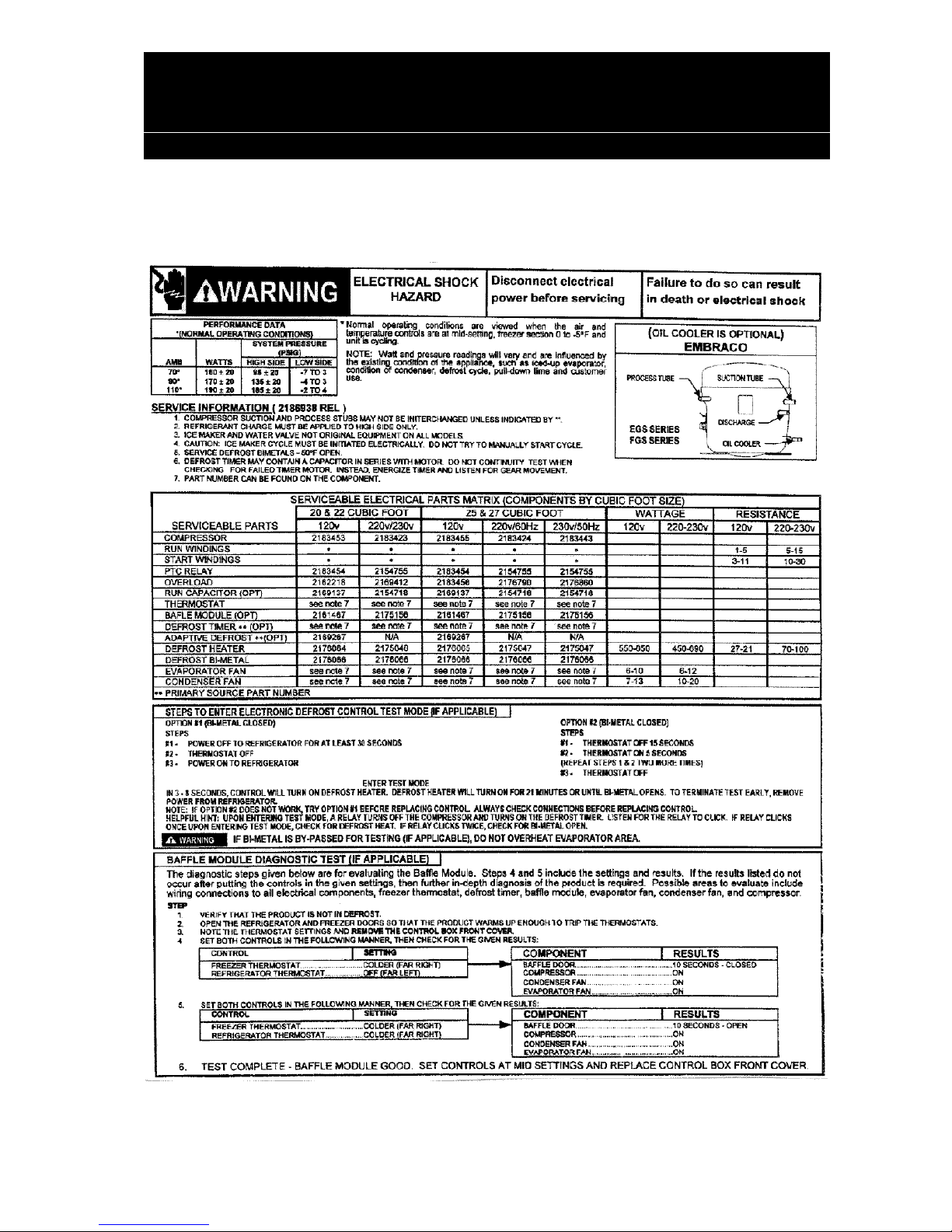
BAFFLE MODULE DIAGNOSTIC TEST - Models 6ED22DQXFW00,
6ED22DQXFB01 and 6ED22DQXFW01
10
SERVICE DATA - Models 6ED22DQXFB02, 6ED22DQXFW02,
6ED22DQXFB03 and 6ED22DQXFW03
11
BAFFLE MODULE DIAGNOSTIC TEST - Models 6ED22DQXFB02 ,
6ED22DQXFW02, 6ED22DQXFB03 and 6ED22DQXFW03
11
CABINET PARTS 12 - 13
REFRIGERATOR LINER PARTS 14 - 15
REFRIGERATOR SHELF PARTS 16 - 17
FREEZER LINER PARTS 18 - 19
AIR FLOW PARTS 20 - 21
MOTOR & ICE CONTAINER PARTS 22 - 23
REFRIGERATOR DOOR PARTS 24 - 25
FREEZER DOOR PARTS 26 - 27
DISPENSER FRONT PARTS 28 - 30
UNIT PARTS 30 - 31
ICEMAKER PARTS 32 - 33
CONTROL PARTS 34 - 35
PARTS NOT ILLUSTRATED AND OPTIONAL PARTS NOT INCLUDED 36
WHIRLPOOL CONSUMER SERVICES
Models 6ED22DQXFW00 6ED22DQXFB01 6ED22DQXFW01
6ED22DQXFB02 6ED22DQXFW02
6ED22DQXFB03 6ED22DQXFW03
Page 3 of 36
SERVICING THE ICE AND WATER DISPENSER
The dispenser housing is “foamed in place” and cannot be removed as an assembly. Components of the dispenser
assembly are serviceable.
WARNING
ELECTRICAL SHOCK HAZARD
Unplug the refrigerator from the electrical power supply before servicing
any electrical components.
Failure to do so can result in serious injury or death.
1. Unplug the refrigerator power cord.
2. Remove the overflow grille from its housing.
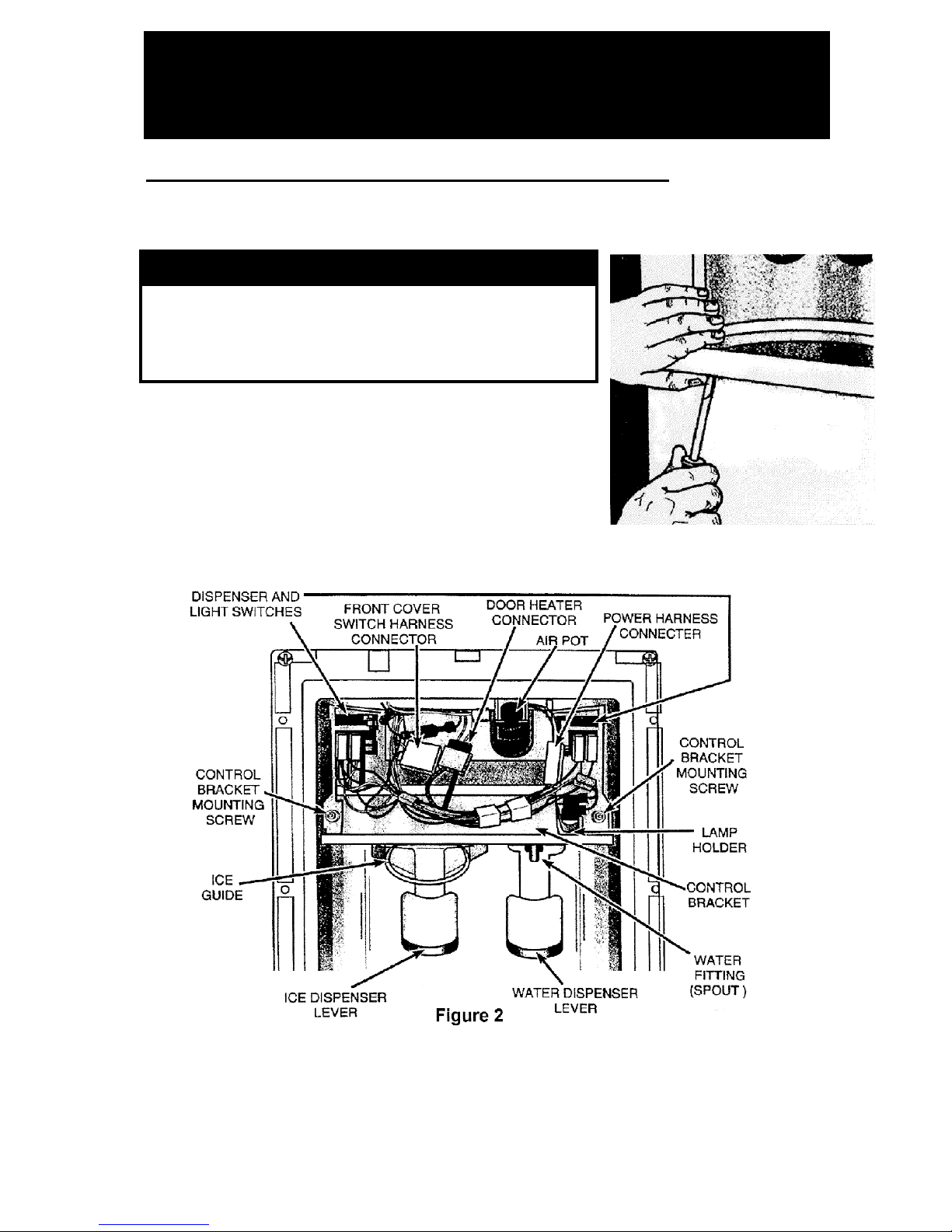
3. Unsnap the front cover at the bottom of the housing
(See Figure 1).
Figure 1
4. Disconnect the front cover switch harness connector and set the cover aside.
Refer to Figure 2 for the following steps :
WHIRLPOOL CONSUMER SERVICES
Models 6ED22DQXFW00 6ED22DQXFB01 6ED22DQXFW01
6ED22DQXFB02 6ED22DQXFW02
6ED22DQXFB03 6ED22DQXFW03
Page 4 of 36
5. Disconnect the power wire harness connector (BL/BL and W wires).
6. Disconnect the flapper door heater wire harness connector (if connected).
7 Release the dispenser micro switch retainers and slide the switches off their locater pins. Carefully handle the
switches so they do not come apart.
8. Disconnect the wires from lampholder terminals.
9. Remove two 1/4” hex head screws from the control bracket and remove the control bracket.
10. Remove the 1/4” hex head screw securing the water fitting (spout) to the water dispenser lever. Remove the
water fitting.
11. Unsnap the ice guide and remove it from the ice dispenser lever.
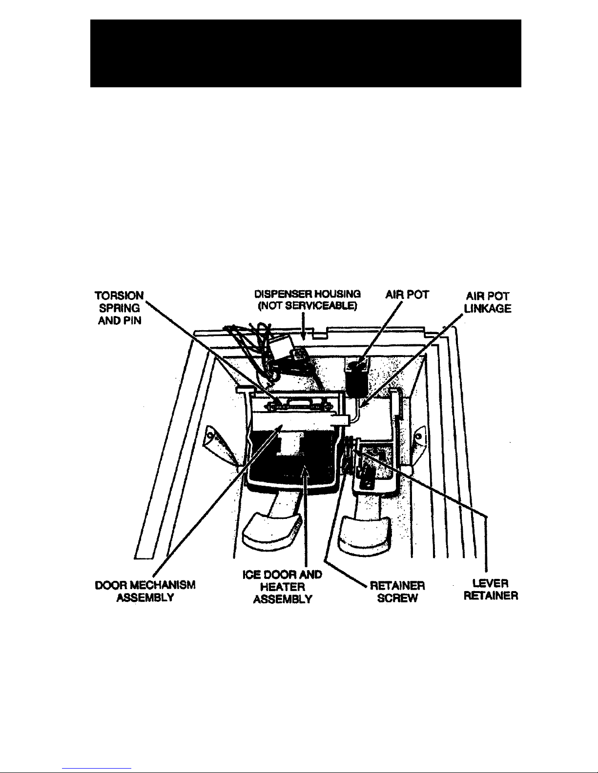
Refer to Figure 3 for the following steps :
Figure 3

WHIRLPOOL CONSUMER SERVICES
Models 6ED22DQXFW00 6ED22DQXFB01 6ED22DQXFW01
6ED22DQXFB02 6ED22DQXFW02
6ED22DQXFB03 6ED22DQXFW03
Page 5 of 36
12. Remove the air pot by sliding by sliding the rear of the air pot out of the slot moulded to the dispenser housing
and slip the linkage out of the flapper door mechanism assembly.
13. Unsnap the flapper door and remove it from the ice dispenser lever. While you remove the flapper door,
carefully guide the flapper door heater wire and connector over the door mechanism assembly.
14. Remove the 1/4” hex head screw securing the dispenser levers pivot retainer to the dispenser housing and
remove the retainer.
15. Remove the water dispenser lever.
16. Remove the ice dispenser lever by maneuvering it around the door mechanism assembly.
17. Pull the pin from the door mechanism assembly and remove the spring and mechanism assembly
18. Re-assemble in the reverse order.
ICE CHUTE FLAPPER DOOR MOISTURE CONTROL
The ice chute flapper door has an inbuilt heating element which is not connected when delivered to the customer. In
extreme circumstances depending on installed position in kitchen or due to extreme humidity conditions, it may be
necessary to connect the heater to control excessive moisture.
To connect the flapper door heater:
1. Unplug the refrigerator power cord.
2. Remove the overflow grille from its housing.
3. Unsnap the front cover at the bottom of the housing (See Figure 1).
4. Plug the ribbon cable from the door to the door heater connector. (See Figure 2)
WHIRLPOOL CONSUMER SERVICES
Models 6ED22DQXFW00 6ED22DQXFB01 6ED22DQXFW01
6ED22DQXFB02 6ED22DQXFW02
6ED22DQXFB03 6ED22DQXFW03
Page 6 of 36
MODULAR ICEMAKER SERVICE
Specifications
Mould Heater : 185 W, 286 ohms
Thermostat : Close -8 ± 1.5°C
Open 0 ± 1.5°C
Water Fill : 140 ml, 7.5 seconds
Motor : 3 Watts, 16900 Ohms
Module : Stamped circuit, plug-
in connections
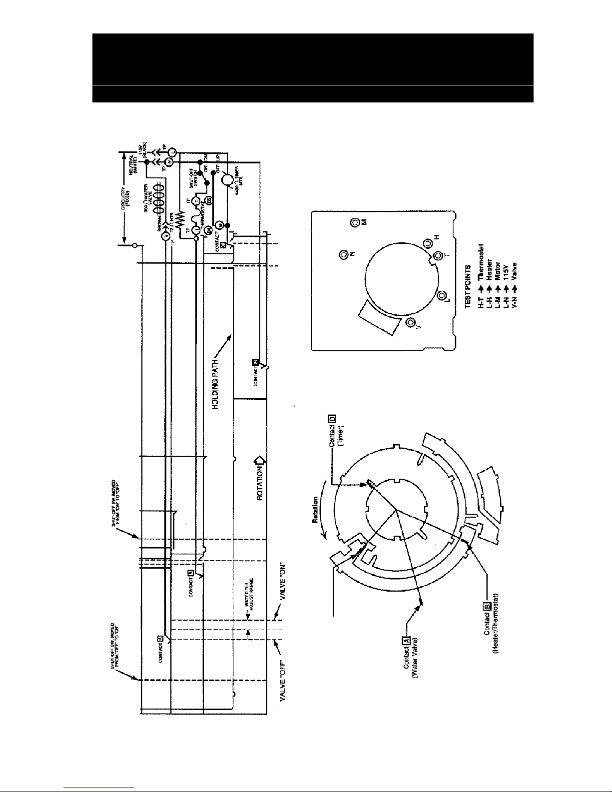
Module Test Points
Module Ohmmeter Checks (No
Power to icemaker and ejector blades in park
position)
Test
Points
Component
Module Position Resist.
Ohms
L-H Mould
Heater
Attached to
support
286
L-M Motor Disconnected
from support
16900
Test
Points
Component
Line Voltage 0 Volts
L - N Module Power OK No
power
T - H Bi-metal Open Closed
L - H Heater On Off
L - M Motor On Off
N - V Water
valve
On Off
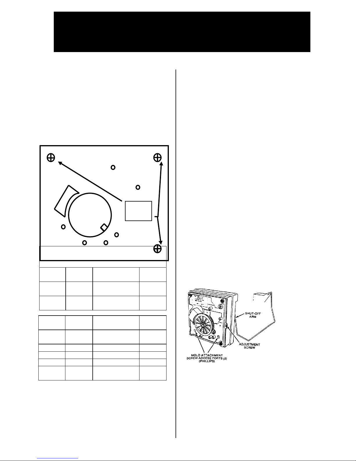
Service Procedures
Cover
Prise plastic pin from right hand side of module
and remove cover.
Module, Motor and Support Assembly
Insert phillips head screwdriver in access ports
in module and remove both screws. Disconnect
shut-off, pull mould from support assembly
Shut-off Arm
Pull out from support. When reassembling
insert to full depth.
Mould and Heater
Remove module, motor and support assembly.
Bi-metal
Remove module and support assembly. Pull
out retaining clips with bi-metal.
Fill Cup
Remove motor, module and support assembly,
remove ejector blades and shut-off arm. Pull
cup from mould.
Ejector Blades and Stripper
Remove module, motor, support assembly.
When reinstalling ejector blades, align “D”
coupling with module cam.
Water Level Adjustment
Turning the screw clockwise decreases the
water fill.
• 1/2 turn equals 20 ml or 1.2 seconds
• full turn equals 40 ml or 2.4 seconds
• Maximum adjustment is one full turn in
either direction. Additional rotation could
damage the module.
N
M
H
TL
V
Remove 3
securing
screws
WHIRLPOOL CONSUMER SERVICES
Models 6ED22DQXFW00 6ED22DQXFB01 6ED22DQXFW01
6ED22DQXFB02 6ED22DQXFW02
6ED22DQXFB03 6ED22DQXFW03
Page 7 of 36
ICEMAKER SCHEMATIC CIRCUIT DIAGRAM
WHIRLPOOL CONSUMER SERVICES
Models 6ED22DQXFW00 6ED22DQXFB01 6ED22DQXFW01
6ED22DQXFB02 6ED22DQXFW02
6ED22DQXFB03 6ED22DQXFW03
Page 8 of 36
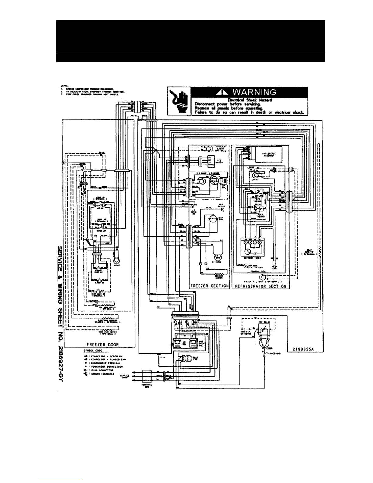
WIRING DIAGRAM - All Models
WHIRLPOOL CONSUMER SERVICES
Models 6ED22DQXFW00 6ED22DQXFB01 6ED22DQXFW01
6ED22DQXFB02 6ED22DQXFW02
6ED22DQXFB03 6ED22DQXFW03
Page 9 of 36
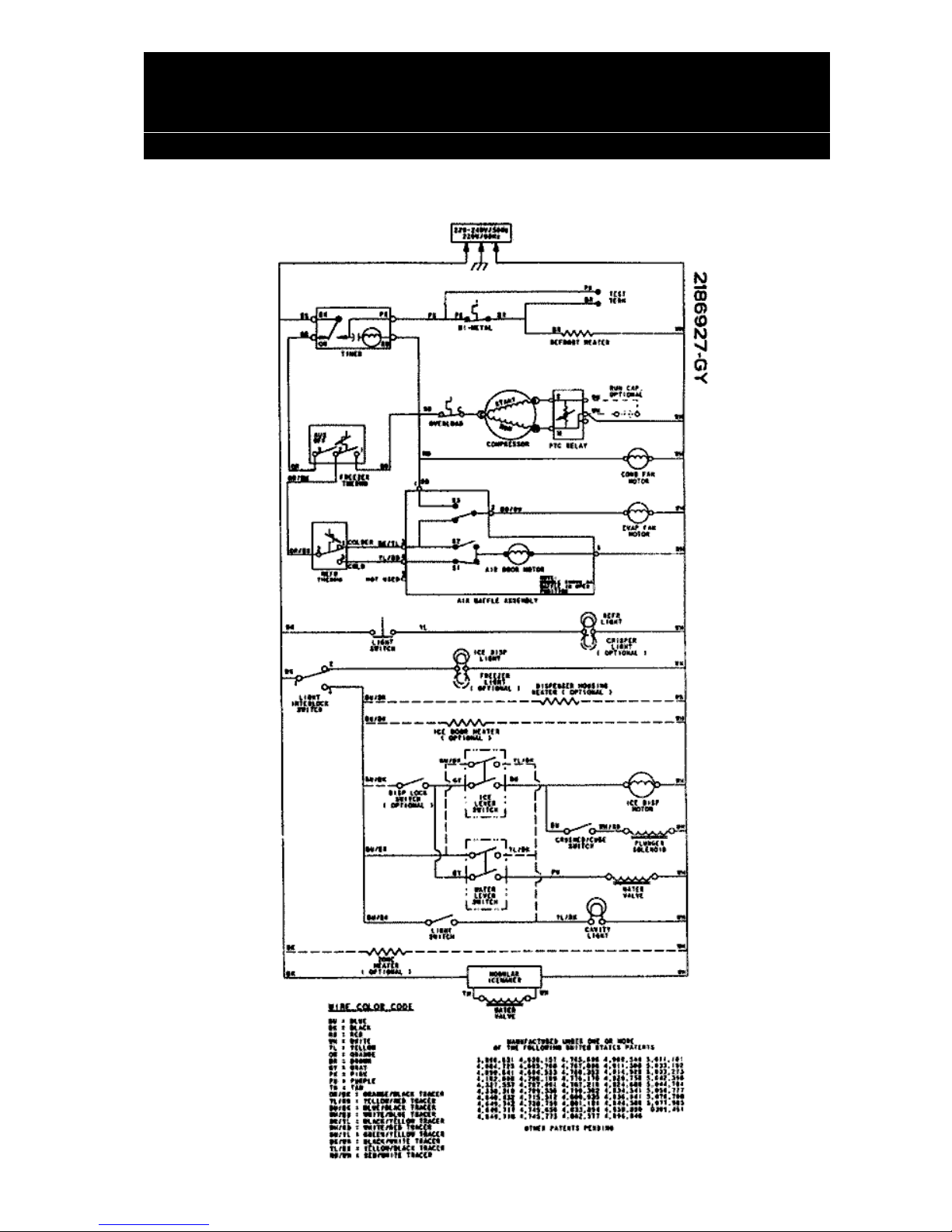
CIRCUIT DIAGRAM - All Models
WHIRLPOOL CONSUMER SERVICES
Models 6ED22DQXFW00 6ED22DQXFB01 6ED22DQXFW01
6ED22DQXFB02 6ED22DQXFW02
6ED22DQXFB03 6ED22DQXFW03
Page 10 of 36
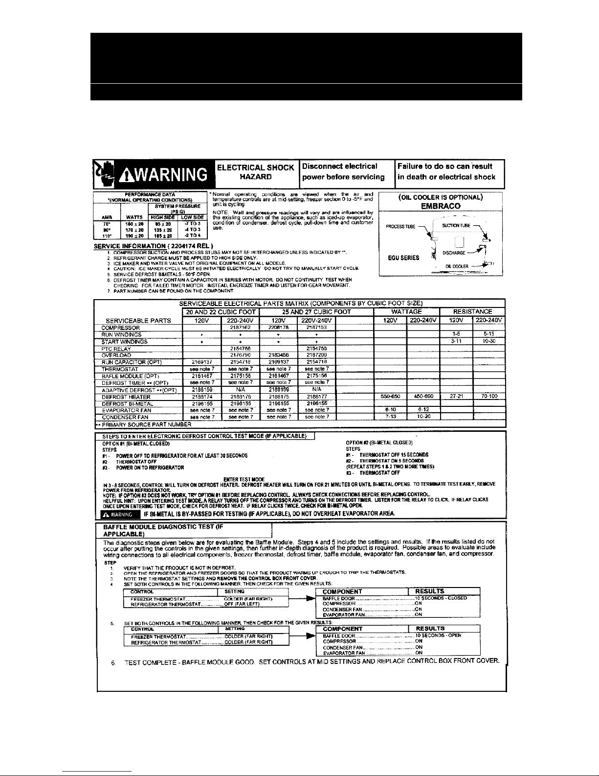
SERVICE DATA - Models 6ED22DQXFW00, 6ED22DQXFB01 and
6ED22DQXFW01
Refrigerant Charge :156 g (5.5 oz.) R134-a
WHIRLPOOL CONSUMER SERVICES
Models 6ED22DQXFW00 6ED22DQXFB01 6ED22DQXFW01
6ED22DQXFB02 6ED22DQXFW02
6ED22DQXFB03 6ED22DQXFW03
Page 11 of 36
SERVICE DATA - Models 6ED22DQXFB02 and 6ED22DQXFW02
6ED22DQXFB03 and 6ED22DQXFW03
7. Refrigerant Charge : 156 g (5.5 oz) R134-a
 Loading...