


Series SPB
Audio Boosters
Installation, Testing,
Operation, and
Maintenance
Manual
Part Number P84748 |
Revision C |
Assembly Number A84749 |
Revision A |
Copyright 2006 Printed in U.S.A. All rights reserved.

About Cooper Wheelock, Inc.: |
Cooper Wheelock, Inc. fulfills its |
|
mission of Helping People Take Action |
|
by providing high quality and advanced |
|
products and services for the life safety, |
|
communications, and security markets. |
|
Cooper Wheelock has served the |
|
needs of commercial, educational, |
|
industrial, health care, and government |
|
users for more than eighty-five years. |
|
Today the company continues to focus |
|
on designing and manufacturing |
|
advanced technological products to |
|
meet the world’s needs for Emergency |
|
Incident Management and Notification, |
|
Multi-Function Communications, and |
|
Mass Notification. |
For more information, contact: |
Cooper Wheelock, Inc. |
|
273 Branchport Avenue |
|
Long Branch, NJ 07740-6899 |
|
Telephone: (800) 631.2148 |
|
Fax: (732) 222.2588 |
|
Web Site: www.cooperwheelock.com |
|
E-Mail: info@cooperwheelock.com |
Series SPB Audio Boosters Manual, Revision A ii

Table of Contents
Chapter: 1 |
Foreword |
1-1 |
||
1.1 |
Intended Use .................................................................................................. |
1-1 |
||
1.2 |
Design Change Disclaimer ............................................................................ |
1-1 |
||
1.3 |
User Operation Assistance............................................................................. |
1-1 |
||
1.4 |
Typographical Notation Conventions ............................................................ |
1-1 |
||
Chapter: 2 |
Safety Precautions |
2-1 |
||
2.1 |
Read This Manual .......................................................................................... |
2-1 |
||
2.2 |
Operational Safety ......................................................................................... |
2-1 |
||
|
2.2.1 |
Expected Equipment Lifecycle .......................................................... |
2-2 |
|
|
2.2.2 |
Periodic Testing ................................................................................. |
2-2 |
|
2.3Compliance with Applicable Codes, Regulations, Laws, Standards, and
Guidelines |
.................................................................................................................. |
2-3 |
|
2.4 |
Property Insurance Recommendation ............................................................ |
2-3 |
|
2.5 |
Audio Output Considerations ........................................................................ |
2-3 |
|
2.6 |
RF Interference .............................................................................................. |
2-4 |
|
2.7 |
General ........................................................................................................... |
2-4 |
|
Chapter: 3 |
Overview |
3-1 |
|
3.1 |
Compatibility with Existing Safepath4 Products ........................................... |
3-1 |
|
3.2 |
Standard Features........................................................................................... |
3-2 |
|
Chapter: 4 |
Installation |
4-1 |
|
4.1 |
Introduction.................................................................................................... |
4-1 |
|
4.2 |
General Installation Instructions .................................................................... |
4-2 |
|
|
4.2.1 Unpacking and Taking Inventory (new from outline) ....................... |
4-2 |
|
|
4.2.2 Mounting the Audio Booster ............................................................. |
4-6 |
|
|
4.2.3 Installing Field Wiring Connections .................................................. |
4-6 |
|
|
4.2.4 Installing Audio and Auxiliary Input Connections ............................ |
4-8 |
|
|
4.2.5 Installing Strobe Input Connections (SPB-80/4) ............................... |
4-9 |
|
|
4.2.6 Installing Audio and Strobe Output Circuit Connections .................. |
4-9 |
|
|
4.2.7 Installing Expansion Output and Trouble Contact Connections...... |
4-11 |
|
|
4.2.8 Installing Power and Battery Connections....................................... |
4-12 |
|
4.3 |
Two-Wire Audio and Four-Wire Audio Modes .......................................... |
4-14 |
|
4.3.1Two-Wire Audio Mode with AC Loss Reported on Main Trouble
Contacts........................................................................................................ |
4-16 |
4.3.2Four-Wire Audio Mode with AC Loss Trouble Reported on Main
Trouble Contacts .......................................................................................... |
4-17 |
4.3.3 Two-Wire Mode with AC Loss Reported on AC TRB Contacts .... |
4-18 |
4.3.4Four-Wire Audio Mode with AC Loss Trouble Reporting on AC TRB
|
Contacts........................................................................................................ |
4-19 |
|
4.4 |
Wiring the Panel .......................................................................................... |
4-20 |
|
|
4.4.1 |
Wiring Guidelines ............................................................................ |
4-20 |
|
4.4.2 |
Field Wiring Connections ................................................................ |
4-20 |
|
4.4.3 |
Visual Notification Appliance Output Wiring (SPB-80/4 only)..... |
4-20 |
Series SPB Audio Boosters Manual, Revision A

|
4.4.4 |
Speaker Notification Appliance Output Wiring .............................. |
4-21 |
|
|
4.4.5 |
Trouble Output Contact Wiring ..................................................... |
4-222 |
|
|
4.4.6 |
Power Connection Requirements................................................... |
4-222 |
|
4.5 |
Mounting the Panel ...................................................................................... |
4-25 |
||
|
4.5.1 |
Locating the Panel............................................................................ |
4-25 |
|
4.6 |
Performing System Checkout ...................................................................... |
4-28 |
||
|
4.6.1 |
System Control Settings................................................................... |
4-28 |
|
|
4.6.2 |
Checkout Procedure ......................................................................... |
4-31 |
|
4.7 |
Ground Fault Detection................................................................................ |
4-31 |
||
4.8 |
Battery Care and Backup Battery Calculations ........................................... |
4-32 |
||
|
4.8.1 |
Caring for Sealed Lead Acid Batteries ............................................ |
4-32 |
|
|
4.8.2 |
Storing Batteries............................................................................... |
4-32 |
|
|
4.8.3 |
Calculating Backup Battery Requirements ...................................... |
4-33 |
|
4.9 |
Installing AC Power and Batteries............................................................... |
4-34 |
||
|
4.9.1 |
Installing AC Power......................................................................... |
4-34 |
|
|
4.9.2 |
Installing Batteries ........................................................................... |
4-34 |
|
Chapter: 5 |
Operation |
5-1 |
||
|
5.1.1 |
Audio Notification Appliance Output Circuit Supervision ............... |
5-2 |
|
|
5.1.2 |
Visual Notification Appliance Output Circuit Supervision (SPB-80/4 |
||
|
only) |
5-2 |
|
|
|
5.1.3 |
Amplifier Supervision........................................................................ |
5-2 |
|
|
5.1.4 |
Ground Fault Supervision .................................................................. |
5-2 |
|
5.2 |
Actions that Initiate Alarms ........................................................................... |
5-2 |
||
Chapter: 6 |
Operational Procedures |
6-1 |
||
Chapter: 7 |
Periodic Testing and Maintenance |
7-1 |
||
7.1 |
Introduction.................................................................................................... |
7-1 |
||
7.2 |
Periodic Testing ............................................................................................. |
7-1 |
||
|
7.2.1 |
Test Frequency................................................................................... |
7-1 |
|
|
7.2.2 |
Equipment .......................................................................................... |
7-1 |
|
7.3 |
Faulty Equipment........................................................................................... |
7-1 |
||
7.4 |
Qualified Personnel........................................................................................ |
7-2 |
||
Chapter: 8 |
Troubleshooting |
8-1 |
||
8.1 |
Introduction.................................................................................................... |
8-1 |
||
8.2 |
Troubleshooting ............................................................................................. |
8-1 |
||
|
8.2.1 |
Procedure A ....................................................................................... |
8-5 |
|
|
8.2.2 |
Procedure B........................................................................................ |
8-5 |
|
|
8.2.3 |
Procedure C........................................................................................ |
8-6 |
|
|
8.2.4 |
Procedure D ....................................................................................... |
8-6 |
|
|
8.2.5 |
Procedure E ........................................................................................ |
8-6 |
|
|
8.2.6 |
Procedure F ........................................................................................ |
8-7 |
|
|
8.2.7 |
Procedure G ....................................................................................... |
8-7 |
|
|
8.2.8 |
Procedure H ....................................................................................... |
8-7 |
|
|
8.2.9 |
Procedure I ......................................................................................... |
8-7 |
|
|
8.2.10 |
Procedure J....................................................................................... |
8-8 |
|
|
8.2.11 Procedure K (SPB-160 Only) .......................................................... |
8-8 |
||
Series SPB Audio Boosters Manual, Revision A iv

|
8.2.12 Procedure L (SPB-160 Only)........................................................... |
8-8 |
||
|
8.2.13 Procedure M (SPB-80/4 Only)......................................................... |
8-9 |
||
|
8.2.14 Procedure N (SPB-80/4 Only) ......................................................... |
8-9 |
||
|
8.2.15 Procedure O (SPB-80/4 Only) ......................................................... |
8-9 |
||
|
8.2.16 Procedure P (SPB-80/4 Only) .......................................................... |
8-9 |
||
Chapter: 9 |
Technical Data |
9-1 |
||
9.1 |
Mechanical ..................................................................................................... |
9-1 |
||
9.2 |
Environmental................................................................................................ |
9-1 |
||
9.3 |
Electrical ........................................................................................................ |
9-2 |
||
|
9.3.1 |
Input ................................................................................................... |
9-2 |
|
|
9.3.2 |
Battery Current Calculations.............................................................. |
9-2 |
|
|
9.3.3 |
Activation Inputs................................................................................ |
9-2 |
|
|
9.3.4 |
Outputs............................................................................................... |
9-2 |
|
9.4 |
Wiring Connections ....................................................................................... |
9-3 |
||
|
9.4.1 End of Line Resistor (1/2W EOLR) .................................................. |
9-3 |
||
Chapter: 10 |
Warranty |
10-1 |
||
10.1 |
Limited Warranty......................................................................................... |
10-1 |
||
10.2 |
Limitation of Liability.................................................................................. |
10-2 |
||
Chapter: 11 |
Battery Calculation Worksheet |
11-1 |
||
Series SPB Audio Boosters Manual, Revision A

This page is left blank intentionally.
Series SPB Audio Boosters Manual, Revision A vi

List of Figures
Figure 3-1 SPB-80/4Audio Booster Panel, Basic Capabilities..................................................... |
3-3 |
|||
Figure 3-2 SPB-160 |
Audio Booster Panel, Basic Capabilities..................................................... |
3-3 |
||
Figure 3-3 SPB-320 |
Audio Booster Panel, Basic Capabilities..................................................... |
3-4 |
||
Figure 3-4 SPB-80/4 Audio Booster Panel .................................................................................. |
3-4 |
|||
Figure 3-5 SPB-160 |
Audio Booster Panel.................................................................................... |
3-5 |
||
Figure 3-6 SPB-320 |
Audio Booster Panel.................................................................................... |
3-5 |
||
Figure 4-1 Location of Field Wiring Connections SPB-80/4....................................................... |
4-3 |
|||
Figure 4-2 Location of Field Wiring Connections SPB-160/SPB-320 ....................................... |
4-4 |
|||
Figure 4-3 Removable Terminal Block ....................................................................................... |
4-6 |
|||
Figure 4-4 Power Limited and Non-Power Limited Wiring ........................................................ |
4-7 |
|||
Figure 4-5 Audio and Auxiliary Input Connections..................................................................... |
4-8 |
|||
Figure 4-6 |
Strobe Input Connections (SPB-80/4) ........................................................................ |
4-9 |
||
Figure 4-7 |
Audio and Strobe Output Connections (SPB-80/4) .................................................. |
4-10 |
||
Figure 4-8 |
Audio Output (SPB-160 and SPB-320) Connections ............................................... |
4-11 |
||
Figure 4-9 |
Alarm and Trouble Connections............................................................................... |
4-12 |
||
Figure 4-10 |
Power and Battery Connections.............................................................................. |
4-13 |
||
Figure 4-11 |
Two-Wire Audio Mode with AC Loss Reported on Main Trouble Contacts......... |
4-16 |
||
Figure 4-12 |
Four-Wire Audio Mode with AC Loss Reported on Main Trouble Contacts ........ |
4-17 |
||
Figure 4-13 |
Two-Wire Audio Mode with AC Loss Reported on AC TRB Contacts ................ |
4-18 |
||
Figure 4-14 |
Four-Wire Audio Mode with AC Loss Trouble Reporting on AC TRB Contacts . 4-19 |
|
Figure 4-15 |
Wiring Diagram for Visual Only Notification Appliances (SPB-80/4 Only)......... |
4-21 |
Figure 4-16 Wiring Diagram for Combination Audio/ Visual Notification Appliances (SPB-80/4
Only) |
................................................................................................................................... |
|
4-21 |
Figure 4-17 ...........................Wiring Diagram for Audio Only Notification Appliance Output |
4-22 |
||
Figure 4-18 ................................................................................Trouble Status Relay Contacts |
4-22 |
||
Figure 4-19 ..........................................Input Power Connection Location, SPB Power Supply |
4-23 |
||
Figure 4-20 .....Input Power Connection Location on the SPB Power Supply (SPB-320 only) |
4-24 |
||
Figure 4-21 ...........................DC and Battery Connection on the Audio Booster Motherboard |
4-25 |
||
Figure 4-22 SPB-80/4 and SPB-160 Audio Booster Panel Mounting and Grounding Location 4-26 |
|||
Figure 4-23 ................................................................................SPB-320 Audio Booster Panel |
4-27 |
||
Figure 4-24 ..................................................................Jumper/Switch Locations on SPB-80/4 |
4-28 |
||
Figure 4-25 ............................................. |
Jumper/Switch Locations on SPB-160 and SPB-320 |
4-29 |
|
Figure 4-26 ................................................ |
Battery Configuration and Wiring (SPB-320 only) |
4-35 |
|
Figure 4-27 ................................... |
Proper Wiring for SPB-320 with and without SPLITTERS |
4-36 |
|
Figure 8-1 ........................................................................................... |
SPB - 80/4 LED Locations |
8-3 |
|
Figure 8-2 ...................................................................... |
SPB - 160 and SPB - 320 LED Locations |
8-4 |
|
Series SPB Audio Boosters Manual, Revision A

This page is left blank intentionally.
Series SPB Audio Boosters Manual, Revision A viii

List of Tables
Table 4-1. |
Series SPB Wiring Modes........................................................................................... |
4-2 |
Table 4-2. |
Terminal Block Connection Definitions ................................................................... |
4-10 |
Table 4-3. |
Jumper/Switch/Variable Resistor Functions ............................................................. |
4-30 |
Table 8-1. |
Trouble LED Procedure Cross Reference................................................................... |
8-2 |
Series SPB Audio Boosters Manual, Revision A

This page is left blank intentionally.
Series SPB Audio Boosters Manual, Revision A
x
1 Foreword
1.1 Intended Use
This manual is designed to serve the installers and operators of the SPB-80/4 Audio Booster (P/N 118988), the SPB-80/4-B Audio Booster (P/N 119931), the SPB-160 Audio Booster (P/N 118989), the SPB-160/B Audio Booster (P/N 119930), and the SPB-320 Audio Booster (P/N 119918) system. All operating instructions, product illustrations, troubleshooting/error messages, and other relevant information are contained in this manual. It is the user’s responsibility to ensure that all instructions in this manual are applied strictly.
1.2 Design Change Disclaimer
Due to design changes and product improvements, information in this manual is subject to change without notice. Cooper Wheelock reserves the right to change product design, including illustrations and diagrams, at any time without notice to anyone, which may subsequently affect the contents of this manual.
Cooper Wheelock assumes no responsibility for any errors that may appear in this manual. Cooper Wheelock will make every reasonable effort to ensure that this manual is up to date and corresponds with the shipped Cooper Wheelock Series SPB Audio Booster.
1.3 User Operation Assistance
Should you experience any difficulty in installing or operating your Series SPB Audio Booster product, please contact your Cooper Wheelock representative. The Troubleshooting chapter in this manual (Chapter 8) includes a list of common system problems, possible causes, and corrective operator actions. The information given here is general. Feel free to contact the Technical Support department of Cooper Wheelock at 1-800-631-2148. Hours are 8:00 a.m. - 7:00 p.m. (Eastern Standard Time), Monday through Thursday and 8:00 a.m. – 5:00 p.m. (Eastern Standard Time) on Friday.
1.4 Typographical Notation Conventions
Thank you for using our products. Use this product according to this instruction manual. Please keep this instruction manual for future reference.
Any material extrapolated from this document or from Cooper Wheelock manuals or other documents describing the product for use in promotional or advertising claims, or for any other use, including description of the product's application, operation, installation and testing is used at the sole risk of the user and Cooper Wheelock will not have any liability for such use.

Foreword
Certain information contained in this manual has been extracted from the NFPA 72 Manual and the Life Safety Code 101™ Manual.
WARNINGS

 WARNING: A Warning indicates a potentially hazardous situation that, if not avoided, could result in serious personal injury or death to you or others. Warnings are set off in boldface type, within boxed rules, indented, and referenced to a warning symbol.
CAUTIONS
CAUTIONS: indicate a situation in which the equipment could be damaged or a situation in which not following the instructions correctly could result in the equipment not working properly. Cautions are set off with a stop sign symbol.
Series SPB Audio Boosters Manual, Revision A 1-2

2 Safety Precautions
2.1Read This Manual
1.Cooper Wheelock recommends that, before performing any actions to specify, apply, install, maintain, and operationally test Series SPB Audio Boosters, personnel properly qualified in the application and use of life safety equipment read this manual carefully.
2.Keep this manual with the Series SPB Audio Booster panel for reference during the life of the system. Make this manual available to all qualified personnel who operate, test, maintain, or service Series SPB Audio Booster products. It is strongly recommend that such personnel read and understand the entire manual.
2.2Operational Safety

 WARNING: If safety precautions, installation, and testing instructions are not performed properly, the Series SPB Audio Boosters may not operate in an emergency situation, which could result in serious injury or death to you and/or others.


 WARNING: If the protective signaling system sounds and/or flashes, it is a warning that a possible serious situation requires immediate attention.
CAUTION: Series SPB Audio Booster printed circuit boards are sensitive to static electricity and have delicate components mounted on it.
(a)Discharge any static electricity from your body by touching a grounded object, such as a metal screw, which is connected to earth ground.
(b)Handle the board by its edges and be careful not to twist or flex it. Install the Series SPB Audio Booster panel in a static-free area.
(c)Attach grounded wrist straps properly before touching any static sensitive areas.
(d)After handling Series SPB Audio Booster printed circuit board, test the panel as described in section 4.6 to verify that it is functioning properly.
NOTE: In areas prone to lighting strikes, using a surge protection device is recommended. Reference TESAN number S002-99 for recommended manufacturers of surge protection equipment.
This TESAN (Technical Engineering Support Application Notice) is available from the Cooper Wheelock website, www.cooperwheelockinc.com, and is found under the Technical Support tab.
Series SPB Audio Boosters Manual, Revision A
2-1

Chapter 2: Safety Precautions
NOTE: This SPB Series Audio Booster panel will not work without power. The SPB Series Audio Booster panel is powered by 120VAC. 24VDC re-chargeable batteries provide backup power. If both sources of power are cut off for any reason, the SPB Series Audio Booster panel will not operate.
1.DO NOT assume any installation, operation and testing details not shown in this manual.
2.2.1Expected Equipment Lifecycle
Notification equipment cannot last forever. Even though the Series SPB Audio Booster is expected to last up to ten years, any of its parts or components could fail before then.
2.2.2 Periodic Testing
1.Cooper Wheelock recommends testing of the entire protective signaling system, including the Series SPB Audio Booster panel, all notification equipment, as well as all messages and their output channel, and priority assignment, at least twice each year, or more often as required by local, state and federal codes, regulations and laws, by qualified personnel.
2.If the notification equipment is not working properly, immediately contact the installer and have all/any problems corrected immediately.
3.Replace any malfunctioning components immediately; do not attempt to repair malfunctioning components. Return malfunctioning components for factory repair or replacement. In the event you cannot contact the installer, contact the manufacturer.


 WARNING: For proper operation in life safety applications, perform the following: (a) Connect the Series SPB Audio Booster panel to a listed compatible and properly operating voice evacuation panel such as the Cooper Wheelock, Inc. SP40S panel, which controls its activation. (b) Ensure that all equipment is properly interconnected and operating. (c) Make sure the installer checks the compatibility of all equipment prior to installation; otherwise, the Series SPB Audio Booster panel and/or the voice evacuation panel may be damaged and/or fail to operate in an emergency situation.


 WARNING: Certain hardware functions on the Series SPB Audio Booster panel are not supervised. If any such hardware functions fail, the Series SPB Audio Booster panel may not provide the intended warning and/or not indicate a trouble condition.
Series SPB Audio Boosters Manual, Revision A 2-2

Chapter 2: Safety Precautions
2.3 Compliance with Applicable Codes, Regulations, Laws, Standards, and Guidelines
Comply with all of the latest applicable codes, regulations, laws, standards, and guidelines.

 WARNING: Ensure that for emergency, life safety applications using the Series SPB Audio Booster, installation, testing and maintenance is always performed by qualified personnel in accordance with all the latest National Fire Protection Association (NFPA), Underwriter’s Laboratory (UL), National Electric Code (NEC), Occupational Safety and Health Administration (OSHA), state, county, local, province, district, federal, and other applicable building and fire standards, guidelines, regulations, laws, and codes including, but not limited to, all appendices and amendments and requirements of the Local Authority Having Jurisdiction (AHJ).
It is recommended that the local Authority Having Jurisdiction (AHJ) inspect and approve the proposed placement of all the notification appliances.
2.4 Property Insurance Recommendation
The Voice Evacuation System containing the SPB Series Audio Booster panel is not a substitute for insurance. Make sure that you have adequate levels of life and property insurance.
2.5 Audio Output Considerations


 WARNING: Audible signals may mask medical equipment monitoring alarms. Where medical equipment monitoring alarms are in use, do not use audible signals; provide visual notification appliances in highly visible locations.
CAUTION: The output of the audio system may not be heard in all cases. Sound can be blocked or reduced by walls, doors, carpeting, wall coverings, furniture, insulation, bed coverings, and other obstacles that may temporarily or permanently impede the output of the audio system. Sound is also reduced by distance and masked by background noise.
The output of the audio system may not be sufficient to alert all occupants, especially those who are asleep, those who are hearing-impaired, those who are wearing devices that plug or cover the ears, and those who have recently used drugs or alcohol.
The output of the audio system may not be heard by an alert person if the output device is placed in an area which is isolated by a closed door, or is located on a different floor from the person in a hazardous situation or is placed too far away
Series SPB Audio Boosters Manual, Revision A
2-3

Chapter 2: Safety Precautions
to be heard over ambient noise such as, but not limited to, running water, traffic, air conditioners, machinery or musical appliances.
If live microphone announcements, audible tones and/or voice messages cannot be readily heard and understood clearly within the protected areas as intended, increase the number and/or sound output intensity of speakers within those areas so that they are heard and understood clearly when activated.
2.6 RF Interference
The Series SPB Audio Booster panel has been tested and found to comply with the limits for a Class A digital device, pursuant to Part 15 of the FCC Rules. These limits are designed to provide reasonable protection against harmful interference when the equipment is operated in a commercial environment. This equipment generates, uses, and can radiate radio frequency energy and, if not installed and used in accordance with the instruction manual, may cause harmful interference to radio communications. Operation of this equipment in a residential area is likely to cause harmful interference in which case the user is required to correct the interference at his own expense.
2.7 General
Each manufacturer's fire alarm control panel and notification appliances operate differently and have different features. Before specifying, installing, operating, testing, maintaining, or servicing a system, carefully read the installation, operation, and testing manual for each piece of equipment and applicable codes.
Additional copies of this manual may be obtained from:
Cooper Wheelock, Inc. 273 Branchport Ave. Long Branch, N.J. 07740 Tel: (800) 631-2148 Fax: (732) 2222588
E-mail: info@cooperwheelockinc.com
Series SPB Audio Boosters Manual, Revision A 2-4

3 Overview
The Series SPB Audio Boosters provide added power for speakers and strobes when the existing power supply’s capacity is not sufficient.
The SPB-80/4 has one 80-watt audio output and two 2-amp strobe outputs for a total of 4 amps of strobe power at 27 volts of DC power.
The SPB-160 has two 80-watt audio outputs for a total of 160 watts. The SPB-160 does not provide strobe power.
The SPB-320 has four 80-watt audio outputs for a total of 320 watts. The SPB-320 also does not supply strobe power.
There is an additional 0.5 amps of auxiliary power at 27VDC that can be used to power other Safepath products. The Series SPB Audio Boosters operate from a primary power source of 120VAC and can accommodate up to a 33AH back-up battery. Up to 12Ah batteries will fit in the enclosure.
3.1 Compatibility with Existing Safepath4 Products
The Series SPB Audio Boosters are fully compatible with the SP40S, all current Audio Splitters (SP4Z-A/B and SP4-APS), the Safepath Remote Microphone (SPRM), the Safepath Volume Control (SP-SVC), the Telephone Zone Controller (SP4-TZC), and the Safepath Remote Microphone Expander (SP4-RMX).
Series SPB Audio Boosters Manual, Revision A
3-1

Chapter 3: Overview
3.2 Standard Features
Feature |
SPB-80/4 |
|
SPB-160 |
SPB-320 |
|
|
|
|
|
Strobe Input Circuit |
Power limited 8-33VDC |
|
No Strobe Circuits. |
No Strobe Circuits. |
|
NAC or CC strobe |
|
|
|
|
Activation |
|
|
|
|
|
|
|
|
Strobe Output Circuit |
• Two - 27VDC, 2A Max |
|
No Strobe Circuits. |
No Strobe Circuits. |
|
regulated NAC |
|
|
|
|
Supervised power |
|
|
|
|
limited strobe outputs. |
|
|
|
|
• Selectable Outputs: |
|
|
|
|
System Wide Wheelock |
|
|
|
|
Sync, Pass Through, or |
|
|
|
|
Constant DC. |
|
|
|
|
• Trouble LED's for open |
|
|
|
|
and short output |
|
|
|
|
conditions. |
|
|
|
|
• Supervised with 10K |
|
|
|
|
Ohm 1/2W EOLR. |
|
|
|
|
|
|
|
|
Audio Input Circuit |
One 1.2 Watt 1V, 25V, |
|
One 1.2 Watt 1V, 25V or |
Two 1.2 Watt 1V, 25V or |
|
or 70.7V input. |
|
70.7V input. |
70.7V input. |
|
|
|
|
|
Audio Output Circuit |
• One 80-Watt, 25V or |
|
• Two 80-Watt, 25V or |
• Four 80-Watt, 25V or |
|
70.7V selectable, |
|
70.7V selectable, |
70.7V selectable, |
|
supervised, power |
|
supervised, power |
supervised, power |
|
limited audio output. |
|
limited audio output. |
limited audio output. |
|
• Trouble LEDs for open |
|
• Trouble LEDs for open |
• Trouble LEDs for open |
|
and short output |
|
and short output |
and short output |
|
conditions. |
|
conditions. |
conditions. |
|
• Supervised with 10K |
|
• Supervised with 10K |
• Supervised with 10K |
|
Ohm 1/2W EOLR. |
|
Ohm 1/2W EOLR. |
Ohm 1/2W EOLR. |
|
|
|
|
|
Battery Standby Sleep |
• When Audio Booster loses AC power, the amplifier section shuts down in order |
|||
Mode |
to conserve battery power. |
|
|
|
|
• The Four-Wire Mode allows non-alarm functions on the SP40S. When an |
|||
|
alarm signal sends a message to the Audio Booster, the amplifier re-energizes |
|||
|
and broadcasts the message. |
|
||
|
• The Two-Wire Mode also shuts off non-alarm functions (BGM, TEL, etc.) on |
|||
|
the SP40S. When a NAC/CC is sent to the AUX IN the Audio Booster will wake |
|||
|
for broadcast. |
|
|
|
Power Supply Selection |
• 120VAC, 3.8A, 50-60Hz input |
• Two separate 27VDC |
||
|
• 27VDC, Up to 33Ah Battery Backup |
Power Supplies |
||
|
• 27VDC, 0.5A Power Output for Splitter |
• 27VDC, Up to 33Ah |
||
|
Connections |
|
Battery Backup |
|
|
|
|
||
Supervision |
Full supervision with on-board diagnostics and trouble reporting circuits for: |
|||
|
Audio NAC circuit wiring ¾ open and short conditions |
|||
|
Ground Fault detection |
|
||
|
Strobe NAC circuit wiring ¾ open and short conditions |
|||
|
Amplifier ¾ operation |
|
||
|
Input voltage/low battery |
|
||
Trouble Reporting |
Form C relay trouble contacts for external notification. |
|
||
|
|
|
|
|
Series SPB Audio Boosters Manual, Revision A 3-2
Chapter 3: Overview
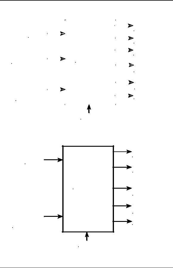
|
|
|
|
|
|
|
|
Audio Out 25V |
|
|
|
|
|
|
|
|
or 70V at 80 Watts, |
|
|
|
|
|
|
|
|
|
Audio In |
|
|
|
|
|
|
|
Supervised |
|
|
|
|
|
|
Strobe 1 Out |
||
25V or 70.7V |
|
|
|
|
||||
|
|
|
|
24VDC at 2A, |
||||
|
|
|
|
|
|
|
|
|
|
|
|
|
|
|
|
|
Supervised |
|
|
|
|
|
|
|
|
Strobe 2 Out |
|
|
|
|
|
|
|
|
24VDC at 2A, |
|
|
|
|
|
|
|
||
Strobe In |
SPB-80/4 |
|
|
|
Supervised |
|||
|
|
|
|
|||||
Closure |
|
|
|
|
||||
8-33VDC or Contact |
|
|
|
|
|
|
Expansion Out |
|
|
|
|
|
|
|
|
|
24VDC at 0.5A |
|
|
|
|
|
|
|
|
in Alarm Condition |
|
|
|
|
|
|
|
|
Supervised |
|
|
|
|
|
|
|
|
DC OUT Constant |
Auxiliary In. For Alarm |
|
|
|
|
24VDC at 0.5A |
|||
Operation of Amplifier |
|
|
|
|
Unsupervised for |
|||
when operating on |
|
|
|
|
|
|
Splitter Power |
|
Battery Only. 8-33VDC |
|
|
|
|
Trouble Form C Relay |
|||
or Contact closure, |
|
|
|
|
||||
|
|
|
|
Rated at 24VDC at 2A |
||||
|
|
|
|
|
|
|
|
|
|
|
|
|
|
|
|
|
|
120 VAC
Figure 3-1 SPB-80/4Audio Booster Panel, Basic Capabilities
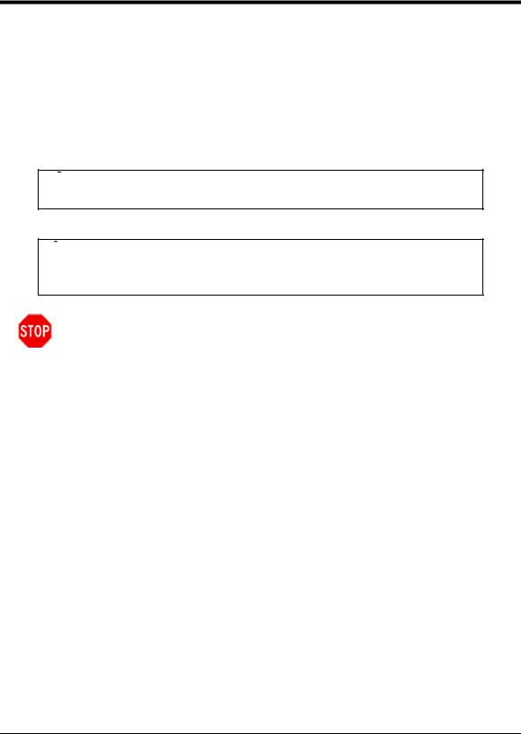
|
|
Audio 1 Out 25V |
|
|
or 70V at 80 Watts, |
Audio In |
|
Supervised |
|
|
|
25V or 70.7V |
|
Audio 2 Out 25V |
|
|
|
|
|
or 70V at 80 Watts, |
|
|
Supervised |
|
SPB-160 |
Expansion Out |
|
24VDC at 0.5A |
|
|
|
|
|
|
in Alarm Condition |
|
|
Supervised |
|
|
DC OUT Constant |
|
|
24VDC at 0.5A |
Auxiliary In. For Alarm |
|
Unsupervised For |
Operation of Amplifier |
|
Splitter Power |
when operating on |
|
|
Battery Only. 8-33VDC |
|
Trouble Form C Relay |
or Contact closure, |
|
Rated at 24VDC at 2A |
120 VAC
Figure 3-2 SPB-160 Audio Booster Panel, Basic Capabilities
Series SPB Audio Boosters Manual, Revision A
3-3

Chapter 3: Overview
Audio In, 25V or 70.7V |
|
Auxiliary In. For Alarm Operation |
|
of Amplifier when operating on |
|
Battery Only. 8-33VDC or Contact |
SPB-320 |
Closure, Reverse Polarity |
|
|
|
1A |
|
|
|
|
Audio 1 Out 25V or 70V |
||||
|
|
|
|
at 80 Watts, Supervised, |
||||||
|
|
|
|
|
|
|
|
|
|
|
|
|
|
|
|
|
|
|
|
|
Power Limited |
|
2A |
|
|
|
|
|
|
Audio 2 Out 25V or 70V |
||
|
|
|
|
|
|
at 80 Watts, Supervised, |
||||
|
|
|
|
|
|
|
|
|
|
|
|
|
|
|
|
|
|
|
|
|
Power Limited |
|
1B |
|
|
|
|
Audio 3 Out 25V or 70V |
||||
|
|
|
|
at 80 Watts, Supervised, |
||||||
|
|
|
|
|
|
|
|
|
|
|
|
|
|
|
|
|
|
|
|
|
Power Limited |
|
2B |
|
|
|
|
Audio 4 Out 25V or 70V |
||||
|
|
|
|
|
|
|
|
|
|
at 80 Watts, Supervised, |
|
|
|
|
|
|
|
|
|
|
Power Limited |
|
X2 |
|
|
|
|
|
Expansion Out 24VDC at 0.5A |
|||
|
|
|
|
|
in Alarm Condition, Supervised, |
|||||
|
|
|
|
|
|
|
|
|
|
|
|
|
|
|
|
|
|
|
|
|
Power Limited |
|
X2 |
|
|
|
|
|
|
DC OUT Splitter Power, |
||
|
|
|
|
|
24VDC at 0.5A, Unsupervised, |
|||||
|
|
|
|
|
|
|
|
|
|
|
|
X2 |
|
|
|
|
|
|
|
|
Non-Power Limited |
|
|
|
|
|
Trouble Form "C" Relay |
|||||
|
|
|
||||||||
|
|
|
|
|
|
|
|
|
|
Rated at 24VDC at 2A |
|
|
|
|
|
|
|
|
|
|
|
|
|
|
|
|
|
|
|
|
|
|
120 VAC
Figure 3-3 SPB-320 Audio Booster Panel, Basic Capabilities
|
GROUNDING |
|
POWER SUPPLY |
TERMINAL |
|
BLOCK |
||
MOTHERBOARD |
||
|
||
|
SPB-80 |
|
|
MOTHERBOARD |
|
12DC 12AH |
12DC 12AH |
|
BATTERY |
BATTERY |
Figure 3-4 SPB-80/4 Audio Booster Panel
Series SPB Audio Boosters Manual, Revision A 3-4

|
Chapter 3: Overview |
|
|
GROUNDING |
|
POWER SUPPLY |
TERMINAL |
|
BLOCK |
||
MOTHERBOARD |
||
|
||
|
SPB-160 |
|
|
MOTHERBOARD |
|
12DC 12AH |
12DC 12AH |
|
BATTERY |
BATTERY |
Figure 3-5 SPB-160 Audio Booster Panel
SPB-160 MOTHERBOARD
SPB-160 MOTHERBOARD
|
|
POWER SUPPLY |
|
|
MOTHERBOARD |
|
|
GROUNDING |
|
|
TERMINAL |
|
|
BLOCK |
|
|
POWER SUPPLY |
|
|
MOTHERBOARD |
|
|
12DC 12AH |
|
|
BATTERY |
12DC 12AH |
12DC 12AH |
12DC 12AH |
BATTERY |
BATTERY |
BATTERY |
Figure 3-6 SPB-320 Audio Booster Panel
Series SPB Audio Boosters Manual, Revision A
3-5

Chapter 3: Overview
This page is left blank intentionally.
Series SPB Audio Boosters Manual, Revision A 3-6
4 Installation
4.1 Introduction
Remember the lives of people depend upon the safe and proper installation of the voice evacuation system and the Series SPB Audio Booster Panel. Please read, understand, and follow the specific installation instructions set forth in this chapter carefully to avoid damage to the panel and equipment connected to it. Ensure that only qualified personnel in accordance with the procedures in this manual conduct the installation.


 WARNING: Shut off all power before starting the installation. Electrical shock can cause death or serious injury.

 WARNING: Do not connect AC power or battery backup power until system wiring has been connected, modules have been installed, and field wiring has been inspected.
CAUTION: The printed circuit board is sensitive to static electricity and has delicate components mounted on it. Before handling the board or any component on it, discharge any static electricity from your body by touching a grounded object such as a metal screw, which is connected to earth ground. Install the panel in a static-free area; properly attach grounded wrist straps before touching any static-sensitive areas.
If you or the installer have any questions about the installation, consult with should consult with the authorities having jurisdiction (AHJ), prior to installation.
Series SPB Audio Boosters Manual, Revision A
4-1

Chapter 4: Installation
4.2 General Installation Instructions
Figures 4-5 and 4-6 show the location of wiring terminals used in the installation of each Series SPB Audio Booster. Table 4-2 identifies and describes the functions of the different wiring terminals.
4.2.1 Unpacking and Taking Inventory (new from outline)
Carefully unpack the panel and make sure each item described on the packing slip is present and undamaged.
1.Check the exterior of the shipping container(s) for any exterior damage, then the interior of the container(s).
2.Notify both the carrier and Cooper Wheelock immediately on the straight bill of lading (supplied by the carrier) if any damage is found both verbally and in writing; you may also request an inspection by the carrier. Such requests must usually be made within a specified time period from date of shipment. Cooper Wheelock is not responsible for damage to equipment occurring during shipping, and only furnishes replacement parts against a written purchase order. It is the customer’s responsibility to file a claim with the carrier.
3.Follow any instructions Cooper Wheelock and/or the carrier may supply about possible damage.
4.If no damage is found, compare the contents of the Inventory List against the contents of the shipping container(s), to ensure receipt of all components.
5.Save all shipping materials (any “bubble wrap” or p lastic) for possible future use. Store in a safe, dry location.
Series SPB Audio Boosters Manual, Revision A 4-2
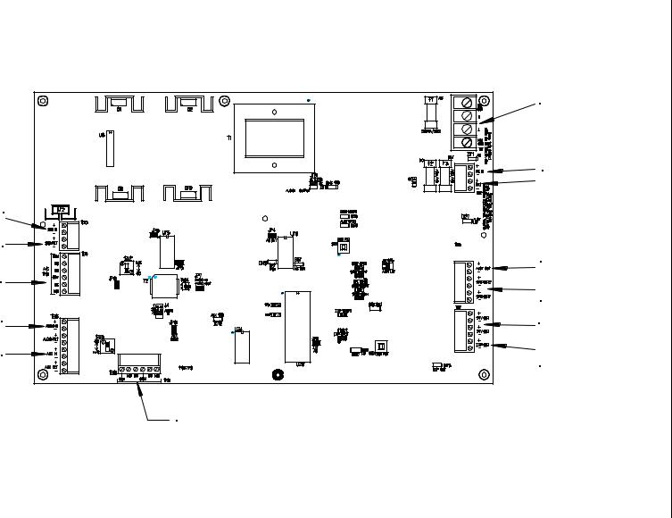
|
1-4 Figure |
Manual, Boosters Audio SPB Series |
80/4-SPB Connections Wiring Field of Location |
A Revision 3-4 |
|
|
|
|
TB1 |
|
|
AC Sensing |
|
|
Input |
|
|
TB2 |
|
|
DC Power Input |
|
|
Battery Connections |
|
TB3 |
|
|
Strobe Input |
|
|
(NAC or CC) |
|
|
Strobe Return |
TB5 |
|
(NAC or CC) |
||
|
Audio Output |
|
TB4 |
Connections |
|
AC Loss |
Strobe |
|
Trouble |
Connections |
|
TB6 |
TB7 |
|
|
||
Audio Input |
Auxiliary 24VDC |
|
Output |
||
|
||
Auxiliary Input |
Expansion |
|
(NAC or CC) |
Output (NAC only) |
|
|
TB5 |
|
|
Trouble Contacts |
Installation 4: Chapter
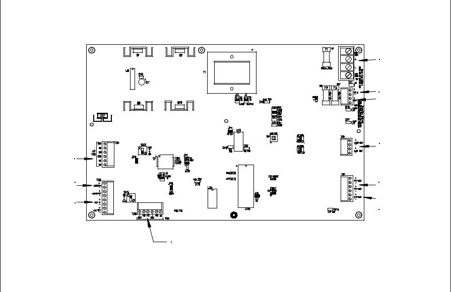
4-4 |
ARevisionManual,Boosters Audio SPB Series |
WiringFieldofLocation 2-4 Figure |
TB4 |
Connections |
Installation 4: Chapter |
|
|
|
|
TB1 |
|
|
|
|
|
AC Sensing |
|
|
|
|
|
Input |
|
|
|
|
|
TB2 |
|
|
|
|
|
DC Power Input |
|
|
|
|
|
Battery Connections |
|
|
|
|
|
TB5 |
|
|
|
Connections |
|
Audio Output |
|
|
|
Auxiliary Input |
Expansion |
|
|
|
|
|
AC Loss |
|
|
|
|
|
Trouble |
|
|
|
|
|
TB6 |
TB7 |
|
|
|
|
Auxiliary 24VDC |
|
|
|
|
|
Audio Input |
|
|
|
|
|
Output |
|
|
|
|
|
|
|
|
|
|
320-160/SPB-SPB |
(NAC or CC) |
Output (NAC only) |
|
|
|
|
TB5 |
|
|
|
|
|
|
Trouble Contacts |
|
 Loading...