


SAFEPATH 4
Telephone Zone
Controller
SP4-TZC P/N 109921
SP4-TZC-P P/N 105590
Installation, Testing,
Operation and Maintenance
Manual
273 Branchport Avenue, Long Branch, NJ 07740-6899 |
Ph: (800) 631-2148 Fax: (732) 222-2588 |
Toll Free 800-631-2148 Web Site: www.cooperwheelock.com E-Mail: info@cooperwheelock.com |
|
Part Number P84567 Revision D |
A84679 C |
Copyright © 2004-2006 Cooper Wheelock, Inc. All rights reserved.
2
|
Table of Contents |
|
Table of Contents .................................................................................................... |
3 |
|
Chapter 1 Application Information ................................................................ |
5 |
|
1.1 Description |
..................................................................................................................... |
8 |
1.2 Connections ................................................................................................................... |
9 |
|
1.2.1 Power.................................................................................................................. |
9 |
|
1.2.2 USB Port ............................................................................................................. |
9 |
|
1.2.3 Telephone Input .................................................................................................... |
9 |
|
1.2.4 Background Music Input........................................................................................ |
9 |
|
1.2.5 Audio Out ............................................................................................................ |
9 |
|
1.2.6 RS485 Digital Control Port..................................................................................... |
9 |
|
1.3 Enclosure ...................................................................................................................... |
|
9 |
1.4 Specifications................................................................................................................. |
10 |
|
1.4.1 Wiring Specifications ............................................................................................ |
10 |
|
Chapter 2 Installation Procedure .................................................................. |
11 |
|
2.1 Notes, Cautions, and Warnings ...................................................................................... |
11 |
|
2.2 Telephone Page Zone Control Mapping Guide .................................................................. |
11 |
|
2.3 Mounting ...................................................................................................................... |
|
11 |
2.4 Wiring the SP4-TZC Zone Controller ................................................................................ |
13 |
|
2.4.1 Removable Terminal Block .................................................................................... |
13 |
|
2.4.2 Wiring the SP4-TZC Zone Controller ...................................................................... |
13 |
|
2.4.2.1 Wiring Connections for SP4-TZC to SP40 and an SP4-APS .............................. |
13 |
|
2.4.2.2 Wiring for SP4-TZC to SP40 with an SP4-APS and Audio Booster |
|
|
|
with Multiple SP4-APS Splitters....................................................................... |
13 |
2.4.2.3 |
Wiring Connections for SP4-TZC with the SP40, Multiple SPB- |
|
|
160s and Multiple SP4-APS Splitter................................................................. |
13 |
2.4.3 Wiring the Paging Telephone to the SP4-TZC ........................................................... |
14 |
|
2.4.3.1 Stand-Alone Telephone or Unused CO Port Wiring............................................ |
14 |
|
2.4.3.2 |
Audio Page Port Wiring.................................................................................. |
14 |
2.4.4 Wiring the Background Music Input ........................................................................ |
15 |
|
2.4.5 Connecting the AUDIO OUT Output........................................................................ |
15 |
|
2.4.6 RS485 Digital Control Port Connection ................................................................... |
16 |
|
2.4.7 RS485 Digital Control Port Connection to Other SP4-APS Splitters........................... |
16 |
|
2.5 Power, Adjusting, and Testing the SAFEPATH® 4 Multi-Function Facility |
|
|
Communications System.............................................................................................. |
17 |
|
2.5.1 Alert Page Tone Selection Jumper Setting................................................................ |
17 |
|
2.5.2 Power Input ........................................................................................................... |
17 |
|
2.5.3 Adjustments on the SP4-TZC Zone Controller ........................................................... |
19 |
|
2.5.4 Testing the SAFEPATH® 4 Multi-Function Facility Communications System |
|
|
Function................................................................................................................ |
19 |
|
Chapter 3 SP4 Telzone Programmer 2 Software Release 2........ |
21 |
|
3.1 About the SP4 Telzone Programmer 2 Software.............................................................. |
21 |
|
3.2 Installing the SP4 Telzone Programmer 2 Software ......................................................... |
21 |
|
3.3 Installing the USB Driver ............................................................................................... |
22 |
|
3.4 SP4 Telzone Programmer 2 Main Screen....................................................................... |
22 |
|
3.4.1 Menu Bar............................................................................................................. |
22 |
|
3.4.1.1 |
File Menu ...................................................................................................... |
23 |
3.4.1.2 |
Edit Menu...................................................................................................... |
23 |
3.4.1.3 View Menu..................................................................................................... |
24 |
|
3.4.1.4 Zone Setup Menu ........................................................................................... |
24 |
|
3.4.1.5 System Info Menu .......................................................................................... |
24 |
|
3.4.1.6 Help Menu ..................................................................................................... |
25 |
|
3
3.4.2 “Get Configuration” Command Button ..................................................................... |
25 |
|
3.4.3 “Send Configuration” Command Button ................................................................... |
25 |
|
3.5 |
Programming and Editing Logical Zone Groups and the Background |
|
|
Music Zone................................................................................................................ |
25 |
3.5.1 Programmed Logical Zone Groups and the Background Music Zone |
|
|
|
Using the Wizard Feature...................................................................................... |
25 |
3.5.2 Manually Programmed/Editing Logical Zone Groups ................................................ |
29 |
|
3.5.3 Warning Message for Duplicate Zones.................................................................... |
31 |
|
3.6 |
SP4 Telzone Programmer 2 Background Music Setup ................................................... |
32 |
3.6.1 Editing Background Music..................................................................................... |
32 |
|
3.7 |
Zone Paging Setup (Enable/Disable) ............................................................................ |
33 |
3.8 |
Editing Silence Detection Timeout................................................................................ |
34 |
3.9 |
Editing Maximum Paging Duration ............................................................................... |
36 |
3.10 Uninstalling the SP4 Telzone Programmer 2 Software................................................. |
37 |
|
Chapter 4 Paging Operation.......................................................................... |
38 |
|
4.1 |
Making A Zone Page .................................................................................................. |
38 |
4.2 |
Making An All-Call Page…………………………………………………………………………38 |
|
Chapter 5 Troubleshooting............................................................................ |
40 |
|
5.1 |
System Reset Switch................................................................................................. |
40 |
5.1.1 Resetting the Network Configuration (Not SP4 Telzone Programmer |
|
|
|
2 Programmed) .................................................................................................... |
40 |
5.1.2 Resetting the Network Configuration (SP4 Telzone |
|
|
|
Programmer 2 Programmed).................................................................................. |
41 |
5.2 |
General Trouble Adjustments....................................................................................... |
43 |
5.3 |
Troubleshooting Using Tone Patterns ........................................................................... |
43 |
5.4 |
Troubleshooting Using the Trouble LED indicators on the PC Board ................................ |
44 |
5.5 |
Troubleshooting Using the “Get Configuration” Command Button..................................... |
46 |
5.6 |
“Send Configuration” Error Messages ........................................................................... |
47 |
5.6.1 “Audio Class of Wiring Mismatch” .......................................................................... |
47 |
|
5.6.2 “Splitters Mismatch” ............................................................................................. |
47 |
|
5.6.3 “Audio Class of Wiring and Number of Splitter Mismatch”......................................... |
47 |
|
5.7 |
Troubleshooting Using the Output Screen on the SP4 Telzone |
|
|
Programmer 2 Software............................................................................................... |
48 |
Chapter 6 Warranty............................................................................................... |
50 |
|
Appendix A Telephone Page Zone Control Mapping ...................................................................... |
A |
|
Appendix B Wiring the SP4-TZC to the SP40 with One SP4-APS Splitter Module ........................... |
B |
|
Appendix C SP4-TZC to SP40 and Audio Booster ........................................................................ |
C |
|
Appendix D SP4-TZC to SP40 and Multiple Audio Boosters .......................................................... |
D |
|
Appendix E SP4-TZC-P Product Description and Application .………………………………………...E |
|
|
4
Chapter 1
Application Information
1.1 Description
The SP4 Telephone Zone Controller (SP4-TZC) controls the zone paging capability of the SAFEPATH®4 Multi-Function Facility Communications System. It is used in conjunction with the SP40 and the SP4-APS (SP4 Addressable Paging Splitter). Audio Boosters SPB-80/4, SPB-160, and SPB-320 can be used in conjunction with the SP40. Each audio booster can use additional SP4-APS splitters, increasing the number of possible paging zones.
The SP4-APS splitter in conjunction with the SP4-TZC allows the End User to make audio zone specific telephone pages and/or have audio zone specific Background Music (BGM) on a Wheelock SAFEPATH®4 Multi-Function Facility Communications System. This can occur as long as the system is not broadcasting a pre-recorded message or when the live microphone is in use. The selective paging and BGM functions are controlled by the SP4-TZC over a RS-485 based digital control network. It also provides a means for expanding one supervised audio output zone to 4 CLASS “B” or 2 CLASS “A” supervised zones. The maximum number of CLASS “B” zones in a system is 68. The maximum number of CLASS “A” zones in a system is 34.
The SP4-TZC can be used with or without the SP4 Telzone Programmer 2 software. The features available without using the software include the use of Individual Zones and Fixed Zone Groups for Zone Paging, and Background Music on all zones. When using the SP4 Telzone Programmer 2 software additional features include Logical Zone Group paging, disabling of Zone Paging (All-Call Paging), user programmable Zone Setup options, and customization of Individual Zones for Background Music.
An Individual Zone is one of the individual outputs from an SP4-APS splitter. The SP4-APS splitter can produce either 2 CLASS “A” or 4 CLASS “B” zones.
A Fixed Zone Group consists of 2 CLASS “A” or 4 CLASS “B” zones on each SP4-APS splitter. For example, if the first SP4-APS splitter is used to cover the zones in the warehouse area the Fixed Zone Group for that area can be paged by keying the two digit Zone Code “71” on the paging phone. The Zone Codes for Fixed Zone Groups are 71 through 87 with each Zone Code matching the order of the splitters.
When used with the SP4 Telzone Programmer 2 software, the SP4-TZC in conjunction with the SP4-APS splitter is capable of programming up to 9 Logical Zone Groups for audio paging. A Logical Zone Group consists of 1 to 5 Individual Zones and/or Fixed Zone Groups. It can also program any Individual Zone for Background Music. The two digit Zone Code for the Logical Zone Groups are “91” through “99”.
Paging an Individual Zone, a Fixed Zone Group, or a Logical Zone Group is accomplished using a touch-tone phone connected to a page port or a touch-tone stand-alone phone. The paging telephone is connected to the SP4-TZC allowing it to key Zone Codes each consisting of two-digit DTMF tones. See Table 1 for the dialing scheme. Any Individual Zone or Fixed Zone Group that is not known by the system will result in a no page condition and the SP4-TZC will start the paging process over.
The SP4 Telzone Programmer 2 software is the second major release of the software, that is designed to operate with an SP4-TZC having firmware version 2.xx. It is NOT backwards compatible with an SP4-TZC having firmware version 1.xx. For SP4-TZC's having firmware version 1.xx, version 1.x.x.x of the SP4 Telzone Programmer software must be used to ensure proper operation.
5
|
|
Table 1 |
|
Dialing Scheme |
|
|
Dialing Scheme |
|
Zone Code |
|
Zones |
00 |
|
All Call |
|
|
|
01 - 68 |
|
Individual Zones |
71 - 87 |
|
Fixed Zone Groups |
91 - 99 |
|
Logical Zone Groups |
|
|
|
Note: Zone Code is the splitter zone DTMF tone.
All splitters must use the same CLASS of wiring (CLASS “A” or “B”) for the audio output zones. See the SP4APS Installation Instructions (P84577) for proper wiring.
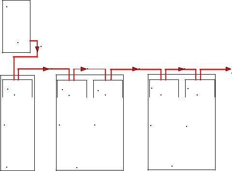
Individual Zone and Fixed Zone Group Zone Codes are controlled by the placement of the splitters in the RS485 digital communication circuit. The first splitter connected to the RS485 digital control port on the SP4TZC will be assigned the first Zone Codes (Individual Zone Codes of “01” and “02” for CLASS “A”, Individual Zone Codes of “01” through “04” for CLASS “B”, and a Fixed Zone Group Code of “71”). Using
the previous example where the first splitter covers the warehouse area, let’s add a second splitter covering the front office area. If the paging zones are set for CLASS “A” then the warehouse will have Individual Zone Codes of “01” and “02”. The front office area Individual Zone Codes will be “03” and “04”. The Fixed Zone Group Code for the warehouse will be “71”, and the front office Fixed Zone Group Code will be “72”
SP4-TZC
RS485 |
CONNECT THE SP4-TZC RS485 CONNECTION |
|
|
|
|
|
TO THE SP40 SP4-APS FIRST. |
|
|
|
|
|
RS485 |
RS485 |
RS485 |
RS485 |
TO ADDITIONAL |
|
|
|
|
|
SP4-APS SPLITTERS |
SP4-APS |
|
SP4-APS |
|
SP4-APS |
|
SP4-APS |
|
SP4-APS |
#1 |
#2 |
#3 |
#4 |
#5 |
||||
INDIVIDUAL |
|
INDIVIDUAL |
|
INDIVIDUAL |
|
INDIVIDUAL |
|
INDIVIDUAL |
ZONE CODES = |
|
ZONE CODES = |
|
ZONE CODES = |
|
ZONE CODES = |
|
ZONE CODES = |
01,02 |
03,04 |
05,06 |
07,08 |
09,10 |
||||
FIXED ZONE |
|
FIXED ZONE |
|
FIXED ZONE |
|
FIXED ZONE |
|
FIXED ZONE |
CODE = 71 |
|
CODE = 72 |
|
CODE = 73 |
|
CODE = 74 |
|
CODE = 75 |
SP40 |
SPB-160 |
SPB-160 |
Figure 1
RS485 Communications Path from SP4-TZC to CLASS “A” SP4-APS Splitters
Figure 1 shows the path of the RS485 digital control loop and the sequence of the splitters in that loop. The SP40 splitter is always the first splitter connected to the RS485 digital control loop. Notice on Figure 1 that the Individual and Fixed Zone Group codes are listed for a CLASS “A” splitter configuration. The SPB-160 is used as an example of an audio booster.
6
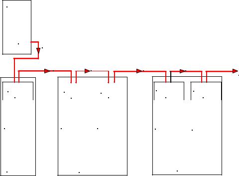
If the paging zones are set for CLASS “B” then the warehouse Individual Zone Codes will be “01” through “04”, and the front office Individual Zone Codes will be “05” through “08”. The Fixed Zone Group Code for the warehouse will still be “71”, and the front office Fixed Zone Group Code will still be “72”. See Figure 2 for a CLASS “B” example.
SP4-TZC
RS485 |
CONNECT THE SP4-TZC RS485 CONNECTION |
|
|
|
|
|
TO THE SP40 SP4-APS FIRST. |
|
|
|
|
|
RS485 |
RS485 |
RS485 |
RS485 |
TO ADDITIONAL |
|
|
|
|
|
SP4-APS SPLITTERS |
SP4-APS |
|
SP4-APS |
|
SP4-APS |
|
SP4-APS |
|
SP4-APS |
#1 |
|
#2 |
|
#3 |
#4 |
#5 |
||
INDIVIDUAL |
|
INDIVIDUAL |
|
INDIVIDUAL |
|
INDIVIDUAL |
|
INDIVIDUAL |
ZONE CODES = |
|
ZONE CODES = |
|
ZONE CODES = |
|
ZONE CODES = |
|
ZONE CODES = |
01,02,03,04 |
05,06,07,08 |
09,10,11,12 |
13,14,15,16 |
17,18,19,20 |
||||
FIXED ZONE |
|
FIXED ZONE |
|
FIXED ZONE |
|
FIXED ZONE |
|
FIXED ZONE |
CODE = 71 |
|
CODE = 72 |
|
CODE = 73 |
|
CODE = 74 |
|
CODE = 75 |
SP40/2 |
SPB-160 |
SPB-160 |
Figure 2
RS485 Communications Path from SP4-TZC to CLASS “B” SP4-APS Splitters
NOTE: 2 CLASS “A” or 4 CLASS “B” Zone Codes are assigned to each splitter. If a zone audio output is not used the Zone Code remains with that splitters.
Appendix A, in the back of this manual, is a Telephone Page Zone Control Mapping Guide which can be used to map the zone locations and Zone Codes. This can assist the technician as well as the user in identifying the locations of the paging zones.
7

1.2 Connections
Figure 3 shows the layout of the SP4-TZC PC Board.
Telephone |
Alert Page |
|
Tone Selection |
||
Input |
||
Jumper |
||
|
||
BGM |
|
|
Volume |
|
|
Adjust |
|
|
|
Page Volume |
|
|
Adjust |
|
Background |
Page Level |
|
Music Input |
||
|
Led Indicators |
|
|
Power On |
|
|
LED Indicator |
|
24VDC |
(Green) |
|
|
||
Input |
|
|
|
Audio |
|
|
Output |
|
Microprocessor |
|
|
PC Board |
|
|
Status |
System Reset |
|
Switch |
||
LED Indicators |
||
|
||
(Green) |
|
|
Communication |
|
|
LED Indicator |
|
|
(Green) |
Microprocessor |
|
|
Alignment Marker |
|
Diagnostic |
RS485 |
|
LED Indicator |
COM Port |
|
(Amber) |
|
|
|
NOTE: OBSERVE |
|
|
CORRECT POLARITY |
Figure 3
SP4-TZC PC Board Layout
8
NOTE: The Microprocessor PC Board should not be removed from the main PC board. If it has been removed, install it by using the Microprocessor alignment marker shown in Figure 3.
Make sure that all pins on the PC board are properly aligned.
1.2.1 Power
The SP4-TZC is powered by a separate 24VDC filtered and regulated power supply which can provide a minimum of 150mA of current. The Wheelock RPS-2406 is a good choice.
1.2.2 USB Port
The USB port is used to program the 9 Logical Zone Groups and Background Music (BGM) using the SP4 Telzone Programmer 2 software included. The default (out of the box) configuration for the SP4-TZC is that all zones have BGM. To program using the USB port, connect an interface cable from the host computer’s USB ports to the USB Series “B” receptacle located on the SP4-TZC. The USB cable should not exceed 10 feet in length. This cable can be purchased using Cooper Wheelock Part Number TZC-USB (109923). The SP4 Telzone Programmer 2 software can also be downloaded from the Cooper Wheelock website (www.wheelockinc.com).
1.2.3 Telephone Input
The PHONE IN (Telephone Input) can accept three different types of devices to activate an audio page: a stand-alone telephone, an unused C.O. port, or a page port. The SP4-TZC provides the stand-alone telephone and unused C.O. port with loop start current in order to operate and provide DTMF tones. The page port must provide 600 Ohm impedance, provide a dry contact, pass loop current, and allow the DTMF tones to pass.
1.2.4 Background Music Input
The monaural Background Music Input shall be a Line Level Signal of 300mVrms at 600 Ohms. Background Music will be automatically muted during a telephone page.
1.2.5 Audio Out
The Audio Out connects the to the SP40 BGM input.
1.2.6 RS485 Digital Control Port
The RS485 Digital Control Port connects to the digital control loop for the SP4-APS splitters.
1.3 Enclosure
The SP4-TZC PC board is mounted in its own enclosure and is designed for indoor use only. Normally, it is mounted next to the SP40 enclosure. The separate 24VDC power supply is mounted outside of the enclosure.
9
1.4 Specifications
The SP4-TZC specifications are listed in Table 2 below.
|
|
Table 2 |
|
|
|
|
|
|
SP4-TZC Specifications |
|
|
||||
|
Specification |
|
|
Value |
|
|
|
|
|
|
|
|
|
|
|
|
Input Voltage |
|
|
24 VDC |
|
|
|
|
|
|
|
|
|
|
|
|
Maximum Current |
|
|
73mA |
|
|
|
|
|
|
|
|
|
|
|
|
Page Input Voltage |
|
|
550mVrms |
|
||
|
|
|
|
|
|
|
|
|
BGM Input Voltage |
|
|
300mVrms at 600 Ohms |
|
||
|
Monaural |
|
|
|
|
|
|
|
|
|
|
|
|
|
|
|
Maximum Distance |
between |
|
2000 ft. |
|
|
|
|
SP4-TZC and the |
first SP4- |
|
|
|
||
|
APS splitter using |
#18AWG |
|
|
|
|
|
|
wire. |
|
|
|
|
|
|
|
|
|
|
|
|
|
|
|
|
|
|
|
|
|
|
The SP4-TZC factory default settings are listed in Table 3 below. |
|
|
|
|
|||
|
|
Table 3 |
|
|
|
|
|
|
Factory Default Settings |
|
|
||||
|
|
|
|
|
|
|
|
|
Setting |
|
|
|
|
Factory Default |
|
Zone Paging (Individual Zone and Fixed Zone Group telephone paging) |
|
Enabled |
|||||
Logical Zone Group paging |
|
|
|
|
Disabled |
||
Background Music |
|
|
|
|
All Zones |
||
Silence Detection Timeout |
|
|
|
|
10 seconds |
||
Maximum Paging Duration |
|
|
|
|
1 minute |
||
Alert Page Tone |
|
|
|
|
ON (Positions 1-2 Alert Page Tone) |
||
BGM Volume |
|
|
|
|
Full Clockwise (Max Volume) |
||
Page Volume |
|
|
|
|
Full Clockwise (Max Volume) |
||
1.4.1 Wiring Specifications
Cable size: All terminal blocks accept #12 - #18 American Wire Gauge (AWG) for single wire connection.
10
Chapter 2
Installation Procedures
2.1 Notes, Cautions, and Warnings
NOTE: All CAUTIONS and WARNINGS are identified by the symbol  . All warnings are printed in bold capital letters.
 WARNING: PLEASE READ THESE INSTRUCTIONS CAREFULLY BEFORE USING THIS PRODUCT. FAILURE TO COMPLY WITH ANY OF THE FOLLOWING INSTRUCTIONS, CAUTIONS AND WARNINGS COULD RESULT IN IMPROPER APPLICATION, INSTALLATION AND/OR OPERATION OF THESE PRODUCTS IN AN EMERGENCY SITUATION, WHICH COULD RESULT IN PROPERTY DAMAGE AND SERIOUS INJURY OR DEATH TO YOU AND/OR OTHERS.
NOTE: Observe all electrical and electronic safety precautions.
This manual assumes that the SP40 has been installed according to the SP40 Installation Manual (P84116) and that the SP4-APS splitter is properly installed according to the SP4-APS Installation Procedure (P84577) in the SP40 enclosure. It also assumes that all Audio Boosters (SPB-80/4, SPB-160, SPB-320) are properly wired according to the SPB-80/4 and SPB-160 Audio Booster Installation Manual (P84296) and/or the SPB-320 (P84244) Installation Manual, and that the SP4-APS splitters are properly installed.
 WARNING: BEFORE INSTALLING THE SP4-TZC ZONE CONTROLLER, MAKE SURE THE POWER IS TURNED OFF AND BATTERIES REMOVED TO ALL COMPONENTS OF THE SAFEPATH®4 MULTI-FUNCTIONAL FACILITY COMMUNICATIONS SYSTEM.
2.2 Telephone Page Zone Control Mapping Guide
Appendix A, at the back of this manual is a Telephone Page Zone Control Mapping Guide which can be used to map the zone locations and Zone Codes. This can assist the technician as well as the user in identifying the locations of the paging zones. The user can create a directory from this guide.
2.3 Mounting
Perform the following steps using Figure 4 as a reference:
STEP 1
STEP 2
STEP 3
Remove the 4 sheet metal screws from the front cover and remove the front cover.
Mount the SP4-TZC to the wall next to the SP40 enclosure using the two keyholes and the two circular holes provided in the base. Be sure to use mounting hardware suitable for the mounting surface.
As required, remove the 3/4" knockouts on the top and bottom of the enclosure for conduit or wire runs.
11

COVER
6.00"


 3/4" KNOCKOUTS
SHEET METAL SCREW
PHILLIPS 1/4" x 3/8"
BLACK (4)
11.00"
3/4" KNOCKOUTS

Figure 4
Mounting diagram
STEP 4 Leave the cover off until all wiring and testing has been completed.
|
STEP 5 |
Mount the external 24VDC Power Supply near the SP4-TZC. Do not connect the wiring to the |
|
SP4-TZC at this time. |
|
|
|
|
|
|
|
12
2.4 Wiring the SP4-TZC Zone Controller
This Section describes the wiring of the SP4-TZC Zone Controller. Following the sequence of Section numbers will ensure a proper installation.
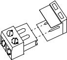
2.4.1 Removable Terminal Block
The terminal blocks on the SP4-TZC are removable. To remove a terminal block, pull the block horizontally from the circuit board as shown in Figure 5. Attach each wire to its proper connections, and plug the terminal block back on the board being careful to match and align the pins.
Figure 5
Removable Terminal Block
2.4.2Wiring the SP4-TZC Zone Controller
2.4.2.1Wiring Connections for SP4-TZC to SP40 and an SP4-APS
To wire the SP4-TZC to the SP40 with one SP4-APS, refer to Appendix B in the back of this manual.
2.4.2.2Wiring Connection for SP4-TZC to SP40 with an SP4-APS and Audio Boosters with Multiple SP4-APS Splitters
SPB-160
To wire the SP4-TZC to the SP40 with one SP4-APS splitter and an Audio Booster with multiple SP4APS splitters, refer to Appendix C in the back of the manual. The diagram uses an SPB-160 Audio Booster because it has two Audio Outputs with a splitter on each.
SPB-80/4
The SPB-80/4 Audio Booster has the same audio terminals as the SPB-160, except that it has a single audio output. Use Appendix C and follow the same wiring sequence as the SPB-160 with a single SP4APS.
2.4.2.3Wiring Connections for SP4-TZC with the SP40, Multiple SPB-160s and Multiple SP4-APS Splitters
SPB-160
Appendix D in the back of this manual shows the proper wiring of the SP4-TZC connected to an SP40 and two SPB-160s with multiple SP4-APS splitters.
SPB-320
Appendix D in the back of this manual also shows the proper wiring of the SP4-TZC connected to an SP40 and two SPB-160s with multiple SP4-APS splitters located in the SPB-320 enclosure.
13

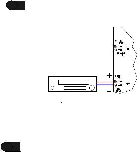
2.4.3 Wiring the Paging Telephone to the SP4-TZC
STEP 6 Connect to the PHONE IN terminal using either Section 2.4.3.1 “Stand-Alone Telephone or Unused CO Port Wiring” or Section 2.4.3.2 “Audio Page Port Wiring”.
2.4.3.1 Stand-Alone Telephone or Unused CO Port Wiring
If a stand-alone telephone or an unused CO port on a telephone system is used, wire the Tip and Ring wires directly to the PHONE IN terminals. The Tip wire is usually green and the Ring wire is usually red. See Figure 6 for the location of the connection on the SP4-TZC.
Figure 6
Stand Alone Telephone or Unused CO Port Wiring
2.4.3.2 Audio Page Port Wiring
If the SP4-TZC is to be connected to an audio page port, the Audio Page Port must provide:
(A)A 600 Ohm, low power page output, capable of passing DC loop current.
(B)Transmission of DTMF tones (touch-tone).
(C)A dry contact that is normally open, closes when paging and reopens when the page is completed.
If these conditions are met, then connect Tip and Ring as shown in Figure 7.
SP4-TZC
Telephone System Telephone Input
Audio Page Port
DRY
CONTACT
RING  (600 OHM OUTPUT)
TIP 
Figure 7
Connecting to a 600 Ohm Audio Page Port
14
2.4.4 Wiring the Background Music Input
STEP 7 Connect the Background Music source to the BGM INPUT terminals. See Figure 8.
NOTE: The Background Music Input shall be a Line Level Signal 2.5V P-P or 300mVrms at 600 Ohms signal.
Background
Music Source
Figure 8
Connecting the Background Music
2.4.5 Connecting the AUDIO OUT Output
STEP 8 Connect the AUDIO OUT from the SP4-TZC to the BGM terminals on the SP40. See Figure 9.
15

SP4-TZC |
|
|
AUDIO OUT |
|
TO SP40 BGM |
|
RS485 COM1 TO |
|
SP4-APS RS485 IN |
|
NOTE: |
|
OBSERVE CORRECT |
USB |
POLARITY |
+ 24V |
|
|
|
|
|
|
|
|
|
|
|
|
|
|
|
|
+ |
|
|
|
|
|
|
|
|
|
|
|
|
|
STB OUT_ |
|
OUT |
IN |
|
OUT |
IN |
Z1 |
Z2 |
Z3 |
Z4 |
EX1 |
EX2 |
|
|
|
+ |
|
RS-485 |
|
ALARM |
|
|
|
|
|
|
||
|
|
|
|
|
|
|
|
|
|
|
|
|||
|
|
|
|
|
|
|
|
|
|
|
|
|
|
|
|
RET _ |
|
|
|
|
|
|
|
SP4-APS |
|||||
|
|
+ |
|
|
|
|
|
|
NAC |
|||||
TB2 |
STB IN_ |
|
|
|
|
|
CC |
CC |
||||||
|
|
NO |
|
|
|
|
|
|
|
|
|
|
||
|
A |
NO |
|
|
|
|
|
SW1 |
|
|
|
|
|
|
|
|
|
|
|
|
|
|
|
|
|
|
|||
|
L |
NC |
|
|
|
|
|
|
B |
|
|
|
|
|
|
M COM |
COM |
|
24 VDC |
|
|
|
|
|
AUDIO |
|
|||
|
|
|
|
CLASS |
|
|
TROUBLE |
|||||||
|
T |
NO |
|
POWER |
OUT |
IN |
|
|
A |
|
|
|
IN |
|
|
|
|
|
|
|
|
|
|
|
|
||||
|
R |
NC |
|
|
|
|
JP1 |
|
SW2 |
|
|
|
|
|
TB3 |
B COM |
|
|
|
|
|
|
|
|
|
|
|
|
|
|
IN3 |
+ |
|
|
|
|
|
|
|
|
|
|
|
|
|
|
_ |
|
|
|
|
|
|
|
|
|
|
|
|
|
IN2 |
+ |
|
|
|
|
|
|
|
|
|
|
|
|
|
_ |
|
|
|
|
|
|
|
|
|
|
|
|
|
|
IN1 |
+ |
|
|
|
|
|
|
|
|
|
|
|
|
|
_ |
|
|
|
|
|
|
|
|
|
|
|
|
|
TB4 |
|
|
|
|
|
|
|
|
|
|
|
|
|
|
|
NR |
+ |
|
|
|
|
|
|
|
|
|
|
|
|
|
_ |
|
|
|
|
|
|
|
|
|
|
|
|
|
|
TEL |
+ |
BGM |
|
|
|
|
|
|
|
|
|
|
|
|
_ |
|
|
|
|
|
|
|
|
|
|
|
||
|
|
+ |
|
|
|
|
|
|
|
|
|
|
|
|
|
|
|
|
|
|
|
|
|
|
|
|
|
|
|
|
BGM _ |
|
|
|
|
|
|
|
|
|
|
|
|
|
TB5 |
|
|
|
|
|
|
|
|
|
|
|
|
|
|
|
|
+ |
|
|
|
|
|
|
|
|
|
|
|
|
AUDIO OUT_ |
|
|
|
|
|
|
|
|
|
|
|
|
||
|
|
+ |
|
|
|
|
|
|
|
|
|
|
|
|
|
CC/NAC _ |
|
|
|
|
|
|
|
|
|
|
|
|
|
|
|
+ |
|
|
|
|
|
|
|
|
|
|
|
|
|
AUX IN _ |
|
|
|
|
|
|
|
|
|
|
|
|
|
TB6 |
|
|
|
|
|
|
|
|
|
|
|
|
|
|
J3 |
|
|
|
|
|
|
|
|
|
|
|
|
|
|
SP40 |
|
|
|
|
|
|
|
|
|
|
|
|
|
|
Figure 9
Audio Out and RS485 Wiring Connections
2.4.6 RS485 Digital Control Port Connection
|
STEP 9 |
Connect the RS485 Digital Control Port terminals from the SP4-TZC to the RS485 IN terminals |
|
on the SP4-APS splitter. See Figure 9. Observe correct polarity. |
|
|
|
2.4.7 RS485 Digital Control Port Connection to Other SP4-APS Splitters
STEP 10
NOTE:
Connect the RS485 OUT from the SP4-APS splitter to the RS485 IN on the next SP4-APS splitter connected to an audio booster (SPB-80/4, SPB-160, SPB-320). Observe proper polarity.
Refer to Section 1.1, Figures 1 and 2. These figures show the order of the connections of the splitters.
16
 Loading...