


AC |
N L |
F2 |
|
|
|
|
+ |
|
+ |
+ |
_ |
|
|
|
|
|
|
|
|
|
IN |
|
BAT |
|
|
|
|
|
|
||||
TB7 |
|
|
|
|
|
|
24V |
|
|
|
|
|
||||
|
|
|
|
|
|
B1 |
|
|
|
|
|
|
|
|
|
|
|
|
|
|
|
|
|
AC |
|
TBL |
|
|
STB |
|
STB OUT+ |
||
|
|
|
|
|
|
|
GRN |
|
YEL |
|
|
RED |
|
|||
|
|
|
|
|
|
|
|
|
|
|
|
|
|
_ |
||
|
SAFEPATH4F1 ON 1 2 3 4 AC D11 D13 D14 |
|
|
|
|
|||||||||||
|
|
|
|
|
|
D9 |
SW1 |
|
|
|
|
|
|
|
+ |
|
W1 |
|
|
SW2 |
|
|
|
|
|
|
|
|
RET_ |
||||
|
|
|
|
|
|
|
|
|
|
|
|
|
|
+ |
||
|
|
|
|
|
|
|
|
|
|
|
|
|
|
|
||
|
|
|
D22 |
DV |
|
D10 |
|
|
|
|
|
|
TB2 |
STB IN _ |
||
|
|
|
D35 |
MIC |
|
BAT |
|
|
|
|
|
|
|
A |
|
NO |
|
|
|
|
|
|
|
|
|
|
|
|
|
L |
|
NC |
|
U8 |
|
RECORD |
SP40/2W2 D37 |
D39 |
|
|
|
|
|
M |
|
COM |
||||
|
|
D36 |
AMP |
|
STB |
|
|
|
|
|
|
T |
|
NO |
||
|
|
D34 |
|
|
SHORT |
|
STB |
|
|
|
|
R |
|
NC |
||
|
|
|
P/N 108985 |
|
OPEN |
|
|
|
TB3 |
B |
COM |
|||||
|
|
|
|
|
1 2 3 R |
|
|
|
||||||||
|
|
|
|
|
|
|
|
|
|
|
||||||
|
|
|
|
SW3 ON 1 2 3 4 |
|
|
|
IN3 |
+ |
|||||||
|
|
|
|
|
|
|
|
|
|
|
|
|
|
IN2 |
+ |
|
|
|
|
P/N 109928 |
|
|
|
|
|
|
|
_ |
|||||
|
|
|
|
|
|
|
|
|
|
IN1 |
+ |
|||||
|
|
|
|
|
|
TEL |
|
TB4 |
_ |
|||||||
|
|
MIC1 |
|
|
|
|
NR |
+ |
||||||||
|
|
|
|
|
|
|
|
|
|
|
|
|
|
|
|
_ |
|
|
|
W8 |
|
W3 |
|
|
|
|
|
|
|
|
|
|
+ |
|
|
|
|
|
|
|
|
BGM |
|
|
|
TEL _ |
||||
|
|
|
|
|
|
|
|
|
|
|
|
|
|
+ |
||
|
Installation, Testing,SW4 |
|
|
|
|
|
|
|||||||||
|
|
|
|
|
BGM _ |
|||||||||||
|
|
|
|
|
|
NAC |
|
TONE |
|
|
|
TB5 |
|
|
+ |
|
|
|
|
|
|
|
|
|
|
|
|
|
|
|
|
|
|
|
|
|
|
|
|
CC |
|
|
|
|
|
|
AUDIO OUT_ |
|||
|
|
|
|
|
|
|
D49 |
AUX |
|
|
|
|
|
|
+ |
|
|
|
|
|
|
|
W5 |
|
|
|
|
|
|
|
|||
|
|
|
|
|
|
|
|
|
|
|
|
CC/NAC _ |
||||
|
|
|
|
|
|
W4 |
|
|
IN |
|
J2 |
|
|
|
|
+ |
|
|
|
|
|
|
|
|
|
|
1V |
|
|
|
|||
|
|
|
|
|
|
D54 |
|
|
|
|
|
|
|
|||
|
|
|
|
|
|
|
|
|
|
|
25V |
|
AUX IN _ |
|||
Operation, and MaintenanceAUX |
|
|
|
|
||||||||||||
|
|
|
|
|
|
AUDIO |
|
|
|
|
|
70V |
TB6 |
|
|
|
|
|
|
|
|
W7 |
SHORT |
|
|
|
|
|
100V J3 |
|
|
|
|
|
|
|
|
|
|
|
|
|
|
|
|
|
|
|
|
|
|
|
|
|
|
|
D58 |
|
|
|
|
|
|
W6 |
|
|
|
|
|
|
|
|
|
|
|
|
|
|
|
|
|
|
|
|
|
|
|
|
|
J4 |
AUDIO |
|
|
|
DV |
|
|
|
|
|
|
|
|
|
|
|
|
OPEN |
|
|
|
|
|
|
|
|
|
|
|
|
|
|
Manual |
|
|
|
|
|
|
|
|
|
|
||
|
|
|
|
|
100V |
|
|
|
GF |
|
|
|
|
|
|
|
|
P84014 REV |
|
|
70V |
|
|
|
|
|
|
E1 |
|
|
|||
|
|
|
|
|
|
|
|
|
|
|
|
|||||
|
|
|
25V |
|
|
D60 |
|
|
|
|
|
|
||||
|
|
|
|
|
|
|
|
|
|
|
|
|
|
|
||
273 Branchport Avenue, Long Branch, NJ 07740-6899 Ph: (732) 222-6880 Fax: (732) 222-2588 Toll Free 800-631-2148 Web Site: www.wheelockinc.com E-Mail: info@wheelockinc.com
Assembly A84162-001 Rev. D
Part Number P84116 Rev. J
Intentionally Blank
ii

Typographical Notation Conventions
Thank you for using our products. Use this product according to this instruction manual. Please keep this instruction manual for future reference.
ANY MATERIAL EXTRAPOLATED FROM THIS DOCUMENT OR FROM WHEELOCK MANUALS OR OTHER DOCUMENTS DESCRIBING THE PRODUCT FOR USE IN PROMOTIONAL OR ADVERTISING CLAIMS, OR FOR ANY OTHER USE, INCLUDING DESCRIPTION OF THE PRODUCT'S APPLICATION, OPERATION, INSTALLATION AND TESTING IS USED AT THE SOLE RISK OF THE USER AND WHEELOCK WILL NOT HAVE ANY LIABILITY FOR SUCH USE.
Certain information contained in this manual has been extracted from the NFPA 72 Manual (1999 Edition) and the Life Safety Code 101™ Manual (2000 Edition).
Notation Conventions
This manual uses the following notation conventions:
 WARNING: INDICATES A POTENTIALLY HAZARDOUS SITUATION THAT, IF NOT AVOIDED, COULD RESULT IN PROPERTY DAMAGE AND SERIOUS PERSONAL INJURY OR DEATH TO YOU AND OR OTHERS.
 CAUTION: Indicates a potentially hazardous situation that, if not avoided, could result in minor or moderate injury. It may also be used to alert against unsafe practices.
Part Number: P84116 Rev. J
Copyright 2005 Wheelock, Inc. All rights reserved.
iii
Intentionally Blank
iv

Table of Contents
Typographical Notation Conventions…………………………………………………………… iii
Table of Contents…………………………………………………………………………………. v
Table of Figures…………………………………………………………………………………… vii
Table of Tables……………………………………………………………………………………. viii
Chapter 1 – Safety Precautions…………………………………………………………………. 1-1
Section 1-1 – Read This Manual…………………………………………………………. 1-1 Section 1-2 – Operational Safety………………………………………………………… 1-1 Section 1-3 – Compliance with Applicable Codes, Regulations, Laws, Standards,
And Guidelines……………………………………………………………. 1-2 Section 1-4 – Property Insurance Recommendation………………………………….. 1-2 Section 1-5 – Audio Output Considerations……………………………………………. 1-2 Section 1-6 – RF Interference…………………………………………………………… 1-3 Section 1-7 – General…………………………………………………………………….. 1-3
Chapter 2 – Overview and Features……………………………………………………………. 2-1
Section 2-1 - Description…………………………………………………………………. 2-1 Section 2-2 – Enclosure and Configuration…………………………………………….. 2-3 Section 2-3 – Nominal Electrical Data………………………………………………….. 2-3 Section 2-4 – Operation Modes…………………………………………………………. 2-4
Chapter 3 – Installation and Setup……………………………………………………………… 3-1
Section 3-1 – Introduction………………………………………………………………… 3-1 Section 3-2 – Fire Alarm Control Panel Wiring Applications…………………………. 3-1 Section 3-3 – General Installation Instructions………………………………………… 3-1
See warning concerning BGM source on page 3-7.
Section 3-5 – Mounting…………………………………………………………………… 3-14 Section 3-6 – System Checkout…………………………………………………………. 3-16 Section 3-7 – Ground Fault Detection Sensitivity Adjustment……………………….. 3-20 Section 3-8 – Battery Care and Backup Battery Calculations………………………... 3-20 Section 3-9 – AC Power and Battery Installation Procedures…………………...…… 3-21
Chapter 4 – Operation…………………………………………………………………………… 4-1
Section 4-1 – Introduction……………………………………………………………….. 4-1 Section 4-2 – Operator’s Console………………………………………………………. 4-1 Section 4-3 – Supervision……………………………………………………………….. 4-1 Section 4-4 – Actions That Initiate Alarms…………………………………………….. 4-2
Chapter 5 – Operational Procedures………………………………………………………….. 5-1
Section 5-1 – Operator Instructions……………………………………………………… 5-1 Section 5-2 – To Make Live Announcements………………………………………….. 5-1 Section 5-3 – To Record Digital Voice Messages……………………………………… 5-1
v
Chapter 6 – Periodic Testing and Maintenance………………………………………………. 6-1
Section 6-1 – Introduction………………………………………………………………… 6-1 Section 6-2 – Periodic Testing…………………………………………………………… 6-1 Section 6-3 – Faulty Equipment…………………………………………………………. 6-1 Section 6-4 – Qualified Personnel………………………………………………………. 6-1 Section 6-5 – Miscellaneous Hardware Testing………………………………………. 6-1
Chapter 7 – Troubleshooting……………………………………………………………………. 7-1
Section 7-1 Introduction………………………………………………….………………. 7-1
Section 7-2 Troubleshooting………………………………….……………..…………… 7-1
Section 7-3 SP40/2 Panel Wiring Diagram……………….……………………………. 7-7
Chapter 8 – Technical Data…………………………………………………………………….. 8-1
Section 8-1 – Mechanical……………………………………………………………….. 8-1 Section 8-2 – Environmental……………………………………………………………. 8-1 Section 8-3 – Electrical………………………………………………………………….. 8-1
Chapter 9 – Module Descriptions…………………………………………………….………… 9-1
Section 9-1 – Introduction………………………………………………..………………. 9-1 Section 9-2 SP40/2 Motherboard ……………………….………………………………. 9-3
Chapter 10 – Warranty……………………………………….………………………………….. 10-1
Battery Backup Calculation Sheet……………………………………….……………………… 11
vi
List of Figures
Figure 2-1 Basic Capabilities of the SP40/2 Panel………………………………………….……..… 2-4
Figure 2-2 Layout of a SP40/2 Panel…………………………………………………………… |
2-5 |
Figure 3-1 Location of Wire Connections………………………………………………………. |
3-2 |
Figure 3-2 Removable Terminal Block………………………………………………………….. |
3-4 |
Figure 3-3 Strobe Input and Output Connections……….…………………………………… |
3-5 |
Figure 3-4 Audio Output Connections…………………………………………………………. |
3-5 |
Figure 3-5 Digital Voice Initiating Connections………….……………………………………… 3-6 |
|
Figure 3-6 Ancillary Audio Input Connections…………………………………………………. |
3-7 |
Figure 3-7 Alarm and Trouble Connections………………………….………………………… |
3-8 |
Figure 3-8 Wiring Diagram for Visual Only Notification Appliances………………………... 3-11 Figure 3-9 Wiring Diagram for Combination Audio/Visual Notification Appliances………… 3-11 Figure 3-10 Wiring Diagram for Audio Only Notification Appliances………………………… 3-11 Figure 3-11 Alarm Relay Contacts……….……………………………………………………… 3-13 Figure 3-12 Trouble Status Relay Contacts……………….……………………………………. 3-13 Figure 3-13 Input Power and Battery Connection Locations……………….…………………. 3-14
Figure 3-14 SP40/2 Panel Mounting and Grounding Location.………..………….………… |
3-15 |
Figure 3-15 Jumper/Switch/Variable Resistor Location……….……………………………. |
3-16 |
Figure 3-16 120VAC Input connection……………………………………….………………… |
3-22 |
Figure 3-17 Battery Wire Connections…………………………………………………………. |
3-23 |
Figure 3-18 Battery Alignment and Jumper Connection………………………………..……. |
3-24 |
Figure 5-1 Digital Voice Section…………………………………………………………………. |
5-3 |
Figure 5-2 SP40/2 Panel Operator Console………………..…….……………………………. |
5-4 |
Figure 7-1 Trouble LED and Fuse Locations………………….…………………………….… |
7-2 |
Figure 7-2 SP40/2 Panel Wiring Diagram….………………………………………………….. |
7-8 |
Figure 9-1 SP40/2 Motherboard………………………………………………………………… |
9-2 |
vii
LIST OF TABLES
Table 3-1 Terminal Connection Definitions……………………………………………………. 3-3 Table 3-2 Jumper/Switch/Variable Resistor Functions…………….……………………… 3-17 Table 3-3 Digital Voice Message Tests………………………………………………………… 3-19 Table 4-1 Alarm Conditions and Results……………………………………………………….. 4-2 Table 6-1 Miscellaneous Hardware Tests………………………………………..……………. 6-2 Table 7-1 Trouble LED Procedure Cross Reference…………………………………………. 7-3 Table 8-1 Input Activation……………………………………………………………………….. 8-2 Table 8-2 Outputs…………………………………………………………………………………. 8-2
viii

Chapter 1 - Safety Precautions
Section 1-1 - Read This Manual
Personnel properly qualified in the application and use of life safety equipment ("qualified personnel") shall read this manual carefully before performing any actions to specify, apply, install, maintain and operationally test SP40/2 products in accordance with the instructions in this manual.
This manual shall be kept with the SP40/2 panel for reference during the life of the system. This manual shall be made available to all qualified personnel who operate, test, maintain, or service SP40/2 products. It is strongly recommend that such personnel read and understand the entire manual.
Section 1-2 - Operational Safety
 WARNING: IF SAFETY PRECAUTIONS, INSTALLATION AND TESTING INSTRUCTIONS ARE NOT PERFORMED PROPERLY, THE SP40/2 PANEL MAY NOT OPERATE IN AN EMERGENCY SITUATION WHICH COULD RESULT IN PROPERTY DAMAGE AND SERIOUS INJURY OR DEATH TO YOU AND/OR OTHERS.
 WARNING: IF THE PROTECTIVE SIGNALING SYSTEM SOUNDS AND/OR FLASHES, IT IS A WARNING THAT A POSSIBLE SERIOUS SITUATION REQUIRES IMMEDIATE ATTENTION.
 CAUTION: SP40/2 printed circuit boards are sensitive to static electricity and have delicate components mounted on it. Discharge any static electricity from your body by touching a grounded object, such as a metal screw, which is connected to earth ground. Handle the board by its edges and be careful not to twist or flex it. The SP40/2 panel is to be installed in a static free area, and the user is to properly attach grounded wrist straps before touching any static sensitive areas. After handling SP40/2 printed circuit board, the panel should be tested in accordance with Section 3-5 “System Checkout” of this manual to verify that it is functioning properly.
NOTE: In areas prone to lighting strikes, using a surge protection device is recommended. Reference TESAN number S002-99 for recommended manufacturers of surge protection equipment.
This TESAN (Technical Engineering Support Application Notice) is available from the Wheelock website, www.wheelockinc.com , and is found under the Technical Support tab.
This SP40/2 panel will not work without power. The SP40/2 panel is powered by 120VAC. 24VDC rechargeable batteries provide back-up power. If both sources of power are cut off for any reason, the SP40/2 panel will not operate.
DO NOT assume any installation, operation and testing details not shown in this manual.
The SP40/2 panel shall only be operated with the dead front panel properly in place.
Notification equipment cannot last forever. Even though SP40/2 is expected to last up to ten years, any of its parts or components could fail before then. Therefore testing of the entire protective signaling system, including the SP40/2 panel, all notification equipment, as well as all messages and their output channel, and priority assignment, shall be conducted at least twice each year, or more often as required by local, state and federal codes, regulations and laws, by qualified personnel. If the notification equipment is not working properly, immediately contact the installer and have all/any problems corrected immediately. Malfunctioning components should be replaced immediately. Do not attempt to repair malfunctioning components. Malfunctioning components should be returned for factory repair or replacement. In the event you cannot contact the installer, contact the manufacturer.
1-1

 WARNING: FOR PROPER OPERATION IN LIFE SAFETY APPLICATIONS, THE SP40/2 PANEL SHALL BE CONNECTED TO A LISTED COMPATIBLE AND PROPERLY OPERATING CONTROL PANEL, WHICH CONTROLS ITS ACTIVATION. ALL EQUIPMENT SHALL BE PROPERLY INTERCONNECTED AND OPERATING. THE INSTALLER SHALL CHECK COMPATIBILITY OF ALL EQUIPMENT PRIOR TO INSTALLATION, OTHERWISE THE SP40/2 PANEL AND/OR THE CONTROL PANEL MAY BE DAMAGED AND/OR FAIL TO OPERATE IN AN EMERGENCY SITUATION.
 WARNING: CERTAIN HARDWARE FUNCTIONS ON THE SP40/2 PANEL ARE NOT SUPERVISED. IF ANY SUCH HARDWARE FUNCTIONS FAIL, THE SP40/2 PANEL MAY NOT PROVIDE THE INTENDED WARNING AND/OR NOT INDICATE A TROUBLE CONDITION.
Section 1-3 - Compliance with Applicable Codes, Regulations, Laws, Standards, and Guidelines
COMPLY WITH ALL OF THE LATEST APPLICABLE CODES, REGULATIONS, LAWS, STANDARDS, AND GUIDELINES.
 WARNING: FOR EMERGENCY, LIFE SAFETY, AND FIRE PROTECTIVE SIGNALING, SYSTEM APPLICATIONS USING THE SP40/2, INSTALLATION, TESTING AND MAINTENANCE SHALL BE
PERFORMED BY QUALIFIED PERSONNEL IN ACCORDANCE WITH ALL THE LATEST NATIONAL FIRE PROTECTION ASSOCIATION (NFPA), UNDERWRITER’S LABORATORY (UL), NATIONAL ELECTRIC CODE (NEC), OCCUPATIONAL SAFETY AND HEALTH ADMINISTRATION (OSHA), STATE, COUNTY, LOCAL, PROVINCE, DISTRICT, FEDERAL, AND OTHER APPLICABLE BUILDING AND FIRE STANDARDS, GUIDELINES, REGULATIONS, LAWS, AND CODES INCLUDING, BUT NOT LIMITED TO, ALL APPENDICES AND AMENDMENTS AND REQUIREMENTS OF THE LOCAL AUTHORITY HAVING JURISDICTION (AHJ).
It is recommended that the local AHJ inspect and approve the proposed placement of all the notification appliances.
NOTE: WHEN INSTALLED IN NYC, THE BACKGROUND MUSIC FEATURE IS NOT PERMISSIBLE. NOTE: WHEN INSTALLED IN NYC, THE TELEPHONE PAGING FEATURE IS NOT PERMISSIBLE
Section 1-4 - Property Insurance Recommendation
The SP40/2 panel is not a substitute for insurance. All users should have adequate levels of life and property insurance.
Section 1-5 - Audio Output Considerations
 WARNING: AUDIBLE SIGNALS MAY MASK MEDICAL EQUIPMENT MONITORING ALARMS. WHERE MEDICAL EQUIPMENT MONITORING ALARMS ARE IN USE, DO NOT USE AUDIBLE SIGNALS; PROVIDE VISUAL NOTIFICATION APPLIANCES IN HIGHLY VISIBLE LOCATIONS.
1-2
 CAUTION: The output of the audio system may not be heard in all cases. Sound can be blocked or reduced by walls, doors, carpeting, wall coverings, furniture, insulation, bed coverings, and other obstacles that may temporarily or permanently impede the output of the audio system. Sound is also reduced by distance and masked by background noise. The output of the audio system may not be sufficient to alert all occupants, especially those who are asleep, those who are hearing-impaired, those who are wearing devices that plug or cover the ears, and those who have recently used drugs or alcohol. The output of the audio system may not be heard by an alert person if the output device is placed in an area which is isolated by a closed door, or is located on a different floor from the person in a hazardous situation or is placed too far away to be heard over ambient noise such as, but not limited to, running water, traffic, air conditioners, machinery or musical appliances.
If live microphone announcements, audible tones and/or voice messages cannot be readily heard and understood clearly within the protected areas as intended, it will be necessary to increase the number and/or sound output intensity of speakers within those areas so that they are heard and understood clearly when activated.
Section 1-6 - RF Interference
The SP40/2 panel has been tested and found to comply with the limits for a Class A digital device, pursuant to Part 15 of the FCC Rules. These limits are designed to provide reasonable protection against harmful interference when the equipment is operated in a commercial environment. This equipment generates, uses, and can radiate radio frequency energy and, if not installed and used in accordance with the instruction manual, may cause harmful interference to radio communications. Operation of this equipment in a residential area is likely to cause harmful interference in which case the user will be required to correct the interference at his own expense.
Section 1-7 - General
Each manufacturer's fire alarm control panel and notification appliances operate differently and have different features. Before specifying, installing, operating, testing, maintaining or servicing a system, carefully read the installation, operation and testing manual for each piece of equipment and applicable codes.
Additional copies of this manual may be obtained from:
Wheelock, Inc.
273 Branchport Ave. Long Branch, N.J. 07740 Tel: (732) 2226880 Fax: (732) 2222588
E-mail: info@wheelockinc.com
1-3
Intentionally Blank
1-4
Chapter 2 - Overview and Features
Section 2-1- Description
General
The SP40/2 panel is a stand alone, single channel, 40 watt, supervised voice evacuation/emergency message system with additional features of a Telephone Page Input, Night Ring Input and Background Music Input. Figure 2-1 illustrates the basic capabilities.
The control panel that activates the SP40/2 panel must provide a Notification Appliance Circuit with a voltage ranging from 9 to 31VDC.
The SP40/2 panel does not sense an emergency condition or hazards such as fire; it is only a part of a system that does sense such conditions. The SP40/2 panel, when activated, provides a pre-recorded voice message(s) to speaker notification appliances. When used as part of a protective signaling system, the SP40/2 panel must be properly connected to a compatible control panel that has been approved by a nationally recognized testing laboratory ("LISTED") and to LISTED compatible notification appliances for proper operation.
THE SP40/2 PANEL MUST BE PROPERLY INSTALLED, PROGRAMMED, AND CONNECTED TO A COMPATIBLE FIRE ALARM CONTROL PANEL TO FUNCTION IN A VOICE EVACUATION SYSTEM.
WHEELOCK EXPRESSLY DISCLAIMS ALL LIABILITY FOR THE CONTENT, CLARITY AND LANGUAGES OF, AND OUTPUT CHANNEL AND PRIORITY LEVEL ASSIGNED TO, ANY AND ALL MESSAGES. IT IS ESSENTIAL THAT YOU HAVE MESSAGE CONTENT AND LANGUAGE, SEQUENCE, OUTPUT CHANNEL AND PRIORITY ASSIGNMENTS REVIEWED AND APPROVED BY QUALIFIED LEGAL AND SAFETY ADVISORS, QUALIFIED REPRESENTATIVE(S) OF OWNER(S) AND USER(S), AND AUTHORITIES HAVING JURISDICTION.
Standard Features
•One strobe NAC output section.
•24VDC @ 2 Amps Maximum.
•Requires separate NAC Circuit (9 to 31VDC) input or can be programmed to operate when Digital Voice messages are played.
•Return allows pass through for Wheelock synchronized strobes, remote SP40/2 panels, additional strobe appliances or EOLR.
•Synchronized output when using Wheelock’s Synchronized strobe products.
•Supervised with 10K Ohm EOLR.
•Trouble LEDs for Open and Short conditions.
•40 Watt Audio Amplifier section.
•Selection of 25Vor 70V speaker output.
•Supervised with 10K Ohm EOLR.
•Trouble LEDs for Open and Short Conditions
2-1
•A Digital Voice Section.
•Capable of playback and record.
•Digital Voice Message Chip contains the recording program and memory for 3 message sections.
•Memory in 3 sections with corresponding inputs.
•Section 1/ IN1; 21 seconds
•Section 2/ IN2; 18 seconds
•Section 3/ IN3; 18 seconds
•Activated by one of three NAC (9 to 31VDC) inputs (IN1, IN2, or IN3).
•Capable of selecting the strobe NAC output for each input.
•Audio Processing Section
•3 Priority ordered audio inputs
Hand held, push-to-talk (PTT) microphone, Priority One. For live, emergency voice announcements and instructions. The microphone overrides (mutes) any voice message or tones in progress.
Auxiliary Input (AUX IN, CC/NAC)
•Priority Two
•CC or NAC initiates AUX IN audio
•CC is supervised. NAC is not supervised.
•For use with SAFTPATH 4 – Remote Microphone Expander (SP4-RMX) or SAFTPATH 4 – Remote Microphone (SPRM)
Digital Voice Section inputs (IN1, IN2, IN3).
•IN1, IN2, and IN3 have priorities 3, 4, and 5 respectively.
•IN1, IN2, and IN3 are not supervised.
•Polarized for compatibility with standard reverse polarity supervision of circuit wiring. Night Ring (NR), Priority 6.
•Contact closure activated.
•Will not operate if the panel is on Battery.
Telephone Page (TEL), Priority 7
•Accepts a Telephone Page Port Input.
•Will not operate if the panel is on Battery.
Background Music (BGM), Priority 8
•Line Level Input
•Will mute when any other input is used.
•Will not operate if the panel is on Battery.
NOTE: WHEN INSTALLED IN NYC, THE BGM FEATURE IS NOT PERMISSIBLE.
2-2
NOTE: WHEN INSTALLED IN NYC, THE TELEPHONE PAGING FEATURE IS NOT PERMISSIBLE.
NOTE: Night Ring, Telephone Page, and Background music will not operate when the SP40/2 is in the alarm condition.
•Power Supply Section.
120VAC, 2.15A 50 - 60Hz input (IN) 24VDC, 12Ah Battery Backup (BAT +/-) 24VDC, 0.5A output terminals (24V +/-)
•Ground Fault Detection Section.
Monitors Inputs and outputs for 600K Ohms minimum in relation to ground.
•A dual-tone tone generator with 2 field selectable sounds (Code 3 Tone, Slow Whoop) that sound when there is a Digital Voice Section Failure in alarm condition.
•Full supervision with on-board diagnostics and trouble reporting circuits for:
Audio NAC circuit wiring open and short conditions
Ground Fault detection
Strobe NAC circuit wiring open and short conditions
PTT Microphone open or not installed condition
Amplifier operation
Digital Voice Section
Input voltage/low battery
•Form C relay trouble contacts for external notification.
•Built in sounder to indicate trouble, with a trouble silence switch to silence it. If the trouble is not corrected in 20 minutes, the sounder will reactivate. (Trouble Silence Switch does not change the state of the Form C Trouble relay.)
•Remote reporting via output contacts for system trouble or alarm activation.
Section 2-2 - Enclosure and Configuration
See Chapter 8 for Technical Specifications
Section 2-3 - Nominal Electrical Data
See Chapter 8 for Technical Specifications.
2-3

BATTERY
STANDBY
MICROPHONE
AUX IN
NIGHT RING
TELEPHONE PAGE PORT 
BACKGROUND MUSIC |
SP40/2 |
|
|
||
|
|
PANEL |
|
TROUBLE |
|
CONTROL |
RELAY |
|
STROBE NAC INPUT |
|
|
SYSTEM
UP TO 3 NAC CIRCUIT INPUTS 
9 TO 31VDC
120VAC
|
CENTRAL AMPLIFIED |
SPEAKER CIRCUIT |
(40 WATT, SELECTABLE |
25V or 70.7V) |
|
|
POWER LIMITED |
STROBE CIRCUIT |
24VDC AT 2A MAX. |
|
POWER LIMITED |
STROBE RETURN |
FOR CONTINUATION OF |
|
STROBE CIRCUIT OR EOLR. |
 CONSTANT 24VDC AT 0.5A POWER LIMITED
 ALARM RELAY FORM C
DIGITAL VOICE MESSAGE CHIP ALLOWS RECORDING 3 MESSAGE SEGMENTS AT THE PANEL. THE PANEL COMES WITH 3 STANDARD PRE-RECORDED MESSAGES. TAILORED MESSAGES CAN BE RECORDED AT WHEELOCK.
Figure 2-1
Basic Capabilities of the SP40/2 Panel
Section 2-4 - Operation Modes
The SP40/2 has two operation modes in the Voice Evacuation Modes:
1.Standby
2.Alarm
Standby Mode
Standby is the normal mode. The SP40/2 panel supervises the connections and internal components to maintain proper operation. All strobes and speaker appliances are off.
The SP40/2 can also be used as a paging system with background music and night ring.
Alarm Mode
Alarm mode occurs when an emergency signal is initiated by the Fire Alarm Control Panel (FACP) or control equipment.
NOTE: Telephone paging is not available when the SP40/2 is in the alarm mode.
2-4

Transformer Motherboard


 L
L


 N
N
AC
+
AC N L |
F2 |
+ |
_ |
+ |
_ |
+ |
_ |
|
TB7 |
IN |
BAT |
24V |
|
||||
|
TB1 |
|
|
|
|
|
|
|
|
|
AC |
|
|
TBL |
|
STB |
+ |
|
F1 |
D11GRN |
|
D13YEL |
|
D14RED |
||
|
|
|
STB OUT_ |
|||||
|
|
1 |
2 |
3 |
4 |
|
AC |
|
|
|
|
RET+ |
|
|
|
ON |
|
|
|
|
SW1 |
|
|
|
|||
W1 |
|
SW2 |
|
|
|
|
D9 |
|
|
|
|
_ |
|
|
|
|
|
|
|
|
|
|
|
|
+ |
||
|
|
|
|
|
|
|
|
|
|
|
|
||
|
|
D22 |
|
|
DV |
|
D10 |
|
|
|
TB2 |
STB IN _ |
|
|
|
D35 |
|
MIC |
|
BAT |
|
|
|
|
A |
NO |
|
|
|
|
|
|
W2 |
|
|
|
|
|
L |
NC |
|
U8 |
RECORD |
|
|
|
AMP |
|
D37 |
D39 |
|
|
|
M COM |
|
|
D36 |
|
|
|
STB |
|
|
|
T |
NO |
|||
|
D34 |
|
|
|
|
SHORT |
STB |
|
|
|
R |
NC |
|
|
|
|
|
|
|
|
|
OPEN |
|
TB3 |
B COM |
||
|
|
|
|
|
|
|
|
SW3 |
1 2 3 R |
|
IN3 |
+ |
|
|
|
|
|
|
|
|
|
1 |
2 3 4 |
|
|||
|
|
|
|
|
|
|
|
|
ON |
|
|
_ |
|
|
|
|
|
|
|
|
|
|
|
|
|
IN2 |
+ |
|
|
|
|
|
|
|
|
|
|
|
|
_ |
|
|
|
|
|
|
|
|
|
|
|
|
|
IN1 |
+ |
|
|
|
|
|
|
|
|
|
|
TEL |
TB4 |
_ |
|
|
|
|
|
|
|
|
|
|
|
|
|
||
|
MIC1 |
|
|
|
|
|
|
|
|
|
|
+ |
|
|
|
|
|
|
|
|
|
|
|
|
NR |
||
|
|
|
|
|
|
|
|
|
|
|
|
|
_ |
|
|
W8 |
|
|
|
W3 |
|
|
|
|
|
TEL |
+ |
|
|
|
|
|
|
|
|
|
BGM |
|
|
_ |
|
|
|
|
|
|
|
|
|
|
|
|
|
+ |
|
|
|
|
|
|
|
|
|
|
|
|
|
BGM |
|
|
|
|
|
|
|
NAC |
SW4 |
|
|
|
|
_ |
|
|
|
|
|
|
|
TONE |
|
TB5 |
|
|
|||
|
|
|
|
|
|
|
|
+ |
|
|
CC |
|
|
|
|
AUDIO OUT_ |
|
|
|
D49 |
AUX |
|
|
|
+ |
|
|
|
W5 |
|
|
|
CC/NAC |
_ |
|
|
|
W4 |
|
IN |
J2 |
|
|
+ |
|
|
D54 |
|
AUX |
1V |
AUX IN |
||
|
|
|
|
25V |
_ |
|||
|
|
AUDIO |
|
|
|
70V |
TB6 |
|
|
|
SHORT |
|
|
|
100V |
|
|
|
W7 |
|
|
|
J3 |
|
|
|
|
|
|
|
|
|
|
||
|
|
D58 |
|
|
|
|
|
|
|
J4 |
AUDIO |
|
|
DV |
|
W6 |
|
|
OPEN |
|
|
|
|
|||
|
100V |
|
|
|
|
|
|
|
|
|
|
GF |
|
|
|
|
|
P84014 REV |
70V |
|
|
|
|
E1 |
|
|
25V |
|
D60 |
|
|
|
|
||
|
|
|
|
|
|
|
||
Grounding
Terminal
Block
Battery Compartment
Figure 2-2.
Layout of SP40/2 Panel
2-5
Intentionally Blank
2-6

Chapter 3 - Installation and Setup
Section 3-1 - Introduction
The lives of people depend upon your safe and proper installation of the SP40/2 panel. Please read, understand and carefully follow the specific installation instructions set forth below to avoid damage to the SP40/2 panel and equipment connected to it. Only qualified personnel in accordance with the procedures in this manual should conduct installation.
 WARNING: SHUT OFF ALL POWER BEFORE STARTING THE INSTALLATION. ELECTRICAL SHOCK CAN CAUSE DEATH OR SERIOUS INJURY.
 WARNING: DO NOT CONNECT AC POWER OR BATTERY BACKUP POWER UNTIL SYSTEM WIRING HAS BEEN CONNECTED, MODULES HAVE BEEN INSTALLED, AND FIELD WIRING HAS BEEN INSPECTED.
 CAUTION: The SP40/2 printed circuit board is sensitive to static electricity and has delicate components mounted on it. Before handling the board or any component on it, discharge any static electricity from your body by touching a grounded object such as a metal screw, which is connected to earth, ground. The SP40/2 panel is to be installed in a static free area and the user is to properly attach grounded wrist straps before touching any static sensitive areas.
The installer, prior to installation should consult with the authorities having jurisdiction (AHJ).
Section 3-2 - Fire Alarm Control Panel Wiring Applications
The SP40/2 Digital Voice Section inputs and the strobe input require an 9 to 31VDC. The Fire Alarm Control Panel (FACP) NAC Circuit of 12VDC or 24VDC will initiate these circuits. The strobe input NAC can be operated separately from the Digital Voice NAC circuits.
“TROUBLE”, Form C relay terminals and an internal sounder are available for monitoring the condition of the SP40/2 panel.
Section 3-3 - General Installation Instructions
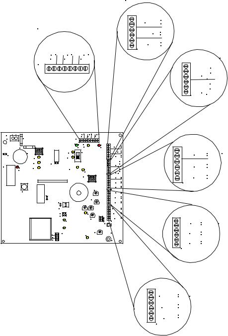
Refer to Figure 3-1 on Page 3-2, which shows the location of wiring connections used in the installation of the SP40/2 panel. Table 3-1 on Page 3-3 explains the functions of the different wiring connections.
3-1
|
|
|
Section 2 |
|
|
|
|
Strobe Connections |
|
Section 1 |
|
|
+ |
|
|
|
STB OUT_ |
|
|
Power Input Connections |
+ |
|
||
|
|
|
RET_ |
|
|
|
|
+ |
|
|
|
|
STB IN _ |
|
|
|
|
TB2 |
Section 3 |
+ |
+ |
+ |
|
|
|
Alarm and Trouble Connections |
|||
IN_ |
BAT_ |
24V_ |
|
|
TB1 |
|
|
A |
NO |
|
|
|
||
|
|
|
L |
NC |
|
|
|
M |
COM |
|
|
|
T |
NC |
|
|
|
R |
NO |
|
|
|
TB3 B COM |
|
AC |
N L |
IN_ |
BAT_ |
24V_ |
|||
TB7 |
|
|
|
F2 |
+ |
+ |
+ |
|
|
|
TB1 |
|
|
||
|
|
|
|||||
|
|
|
D11AC |
TBL |
F1 |
|
|
GRN YEL |
|
1 |
2 |
3 |
4 |
|
SW2 |
|
|
AC |
SW1 |
W1 |
|
|
|
|
DV |
|
|
BAT |
|
|
|
MIC |
W2 |
|
U8 |
RECORD |
AMP |
STB |
|
|
SHORT |
STB |
||
|
D31 |
|||
|
|
|
|
OPEN |
SW3 |
1 2 3 R |
1 2 3 4 |
MIC1 |
TEL |
|
|
||
W3 |
|
|
|
BGM |
|
NAC |
|
|
|
TONE |
|
CC |
|
|
W5 |
AUX |
|
IN |
||
W4 |
|
|
AUDIO |
AUX |
|
SHORT |
|
|
AUDIO |
DV |
|
OPEN |
||
100V |
GF |
|
70V |
||
|
||
25V |
|
STB |
|
+ |
RED |
STB OUT_ |
|
|
|
+ |
|
RET _ |
|
|
|
+ |
TB2 |
STB IN _ |
|
|
|
|
|
A |
NO |
|
L |
NC |
|
M COM |
|
|
T |
NC |
|
R |
NO |
TB3 |
B COM |
|
|
IN3 |
+ |
|
_ |
|
|
IN2 |
+ |
|
_ |
|
|
IN1 |
+ |
TB4 |
_ |
|
|
NR |
+ |
|
|
_ |
|
TEL |
+ |
|
BGM |
+ |
|
_ |
|
TB5 |
|
|
|
|
+ |
AUDIO OUT_ |
||
|
|
+ |
|
CC/NAC _ |
|
+
1V AUX IN _
25V
70V
100V TB6
J3
 W6
W6
E1
Section 4
Internal Digital Voice
IN3 + Module Input Connections
_
IN2 +
_
IN1 +
_
TB4
Section 5
Night Ring, Telephone Page,
+ Background Music Connections
NR _
TEL +_
+
BGM _
TB5
Section 6
Audio Output Connections
AUDIO OUT_+ Auxiliary Input Connections
+
CC/NAC _
+
AUX IN _
TB6
Figure 3-1
Location of Field Wiring Connections
3-2
Table 3-1
Terminal Connection Definitions
|
Symbol |
Full Name |
Definition |
|
|
|
|
TB1 |
|
Terminal Block 1 (Section 1) |
|
|
IN |
28VDC Input Connection |
28VDC Connection from Rectifier Module |
|
BAT |
Battery Input Connection |
24VDC, 12AH Battery Input Connection |
|
24V |
24VDC 0.5A Output |
24VDC, 0.5A Continuous Output Connection, Power Limited auxiliary power |
|
|
|
source |
TB2 |
|
Terminal Block 2 (Section 2) |
|
|
STB OUT |
Strobe Output |
24VDC, 2A Maximum Strobe NAC Output Supervised with UL Listed 10K |
|
|
|
Ohm, ½ W EOLR. (Power limited) |
|
RET |
Return |
Strobe Input Return for connecting additional strobe circuits, or UL Listed |
|
|
|
10K Ohm, ½ W EOLR. |
|
STB IN |
Strobe Input |
9-31VDC Strobe NAC Input. Triggers Strobes in Alarm Condition |
TB3 |
|
Terminal Block 3 (Section 3) |
|
|
ALM |
ALARM CONNECTIONS |
Alarm Form C relay changes state in Audio Alarm Conditions. These |
|
|
|
conditions are: Push-to-talk Button on MIC depressed. AUX initiated via CC |
|
|
|
or NAC, and IN1, IN2, and IN3 inputs present. Contacts are rated at 24VDC, |
|
|
|
2A. Resistive load. |
|
NO |
Normally Open |
Alarm Relay contact open to Common (COM) in non alarm condition. |
|
NC |
Normally Closed |
Alarm Relay contact closed to Common (COM) in non alarm condition. |
|
COM |
Common |
Alarm Relay Common (COM) |
|
TRB |
TROUBLE CONNECTIONS |
Trouble Form C relay changes state in panel trouble condition. Contacts are |
|
|
|
rated at 24VDC, 2A. Resistive load. |
|
NO |
Normally Open |
Trouble Relay contact open to Common (COM) in non alarm condition |
|
NC |
Normally Closed |
Trouble Relay contact closed to Common (COM) in non alarm condition |
|
COM |
Common |
Trouble Relay Common (COM) |
TB4 |
|
Terminal Block 4 (Section 4) |
|
|
IN3 |
Input 3 |
Digital Voice initiating connection for message #3. (9-31VDC). Input 3 is a |
|
|
|
Priority 5 circuit. Reverse polarity. |
|
IN2 |
Input 2 |
Digital Voice initiating connection for message #2. (9-31VDC). Input 2 is a |
|
|
|
Priority 4 circuit. Reverse polarity. |
|
IN1 |
Input 1 |
Digital Voice Initiating Connection for message #1. (9-31VDC). Input 1 is a |
|
|
|
Priority 3 circuit. Reverse polarity. |
TB5 |
|
Terminal Block 5 (Section 5) |
|
|
NR |
Night Ring |
Contact Closure Input initiates chime sound for Night Ring. Non-supervised. |
|
|
|
Night Ring does not operate without 120VAC input and the Panel is |
|
|
|
operating on Battery. |
|
TEL |
Telephone Page Input |
Telephone Page Input from a telephone Page Port. Non-Supervised. |
|
|
|
Telephone Page does not operate without 120VAC input and the Panel is |
|
|
|
operating on Battery. |
|
BGM |
Background Music Input |
Line Level, 600 Ohm Background Music Input. Automatically mutes when |
|
|
|
any other input is in use. Non-Supervised. Background Music input does not |
|
|
|
operate without 120VAC input and the panel is operating on Battery |
TB6 |
|
Terminal Block 6 (Section 6) |
|
|
AUDIO OUT |
Audio Output |
Audio Output for 25V or 70V speakers. Supervised using UL Listed 10K |
|
|
|
Ohm, ½ W EOLR. Power Limited. |
|
CC/NAC |
Contact Closure/NAC |
Contact closure or NAC will initiate AUX IN Audio. CC is supervised. |
|
|
|
Connects to RMX or Remote MIC |
|
AUX IN |
Auxiliary Input Audio |
Line Level Audio Input from RMX or Remote MIC |
TB7 |
|
Terminal Block 7 |
|
|
AC |
AC Monitor Input |
Monitors the AC input voltage and senses when the voltage is too low or not |
|
|
|
present and energizes the battery circuit. See Figure 7-2 (Page 7-8) |
|
|
|
|
NOTE: All Outputs (Strobe Output, Audio Output, and 24VDC Auxiliary Power Source) are power limited circuits.
3-3
 Loading...