

Page 1
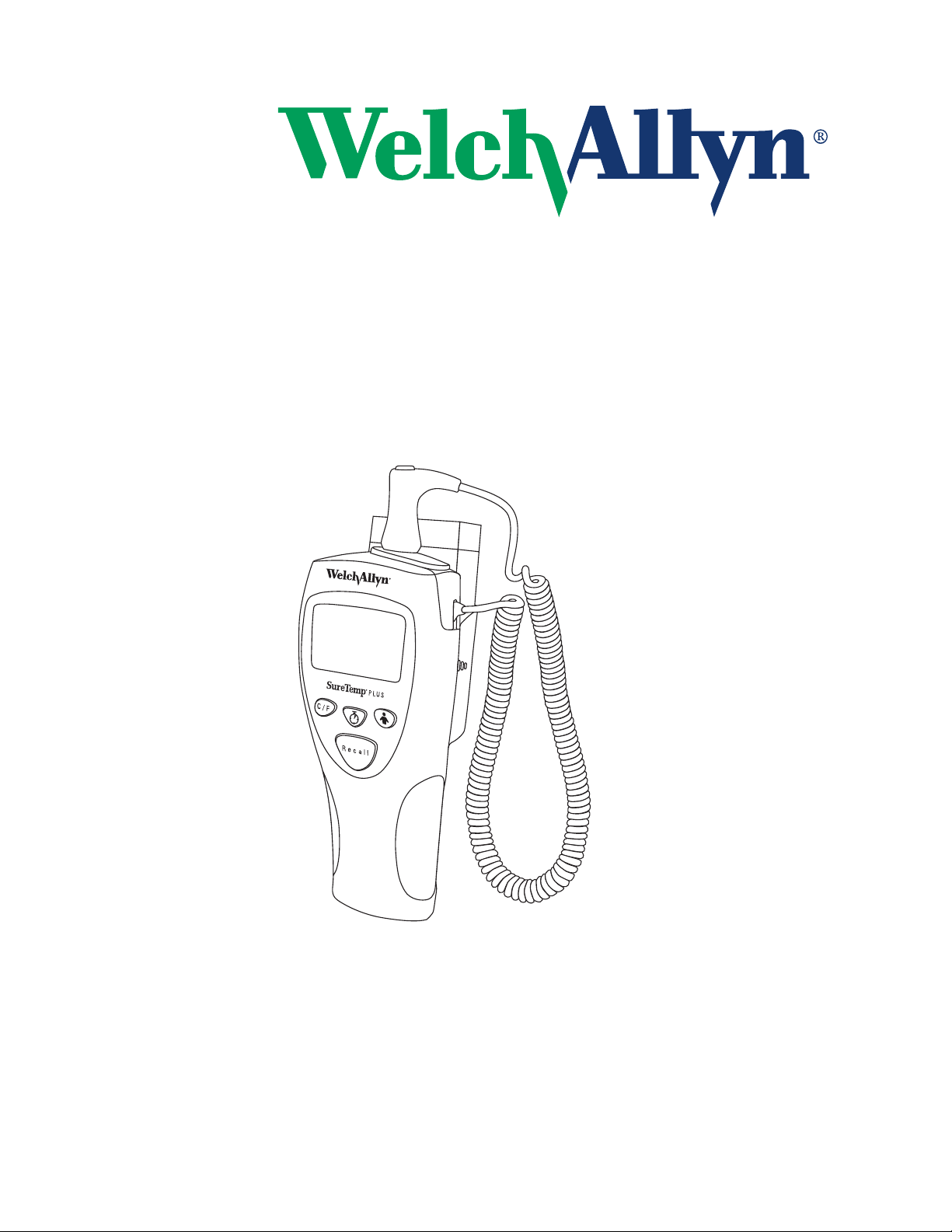
Service Manual
®
SureTemp
690 and 692 Series
Plus
Page 2
© 2018 Welch Allyn, Inc. To support the intended use of the product described in this
publication, the purchaser of the product is permitted to copy this publication, for internal
distribution only, from the media provided by Welch Allyn.
Welch Allyn assumes no responsibility for any injury, or for any illegal or improper use of
product, that may result from failure to use this product in accordance with the
the
instructions, cautions, warnings, or indications for use published in this manual.
Welch Allyn is a registered trademark of Welch Allyn, Inc.
Patent information
For patent information, please visit www.welchallyn.com/patents.
Welch Allyn Technical Support:
http://www.welchallyn.com/about/company/locations.htm
80021463 Ver. A
Revision date: 2018-05
Welch Allyn, Inc.
4341 State Street Road
Skaneateles Falls, NY 13153 U.S.A
www.welchallyn.com
901053 ELECTRONIC THERMOMETER
Regulatory Affairs Representative
Welch Allyn Limited
Navan Business Park
Dublin Road, Navan
County Meath, Republic of Ireland
Page 3

Table of Contents
1 General Information . . . . . . . . . . . . . . . . . . . . . . . . . . . . . . . . . . . . . . . . . . . . . . . . . . . . . . . . . . 1
1.1 About this Manual . . . . . . . . . . . . . . . . . . . . . . . . . . . . . . . . . . . . . . . . . . . . . . . . . . . . . . . . . .1
1.2 Safety and Warnings . . . . . . . . . . . . . . . . . . . . . . . . . . . . . . . . . . . . . . . . . . . . . . . . . . . . . . . . 1
1.3 Conforms with . . . . . . . . . . . . . . . . . . . . . . . . . . . . . . . . . . . . . . . . . . . . . . . . . . . . . . . . . . . . . 3
1.4 Symbols and descriptions . . . . . . . . . . . . . . . . . . . . . . . . . . . . . . . . . . . . . . . . . . . . . . . . . . . . 3
2 Operating Characteristics . . . . . . . . . . . . . . . . . . . . . . . . . . . . . . . . . . . . . . . . . . . . . . . . . . . . . . 6
2.1 Basic System Description . . . . . . . . . . . . . . . . . . . . . . . . . . . . . . . . . . . . . . . . . . . . . . . . . . . .6
2.2 Model Features . . . . . . . . . . . . . . . . . . . . . . . . . . . . . . . . . . . . . . . . . . . . . . . . . . . . . . . . . . . . 8
2.3 Operating Features . . . . . . . . . . . . . . . . . . . . . . . . . . . . . . . . . . . . . . . . . . . . . . . . . . . . . . . . . 8
2.4 Instrument Security . . . . . . . . . . . . . . . . . . . . . . . . . . . . . . . . . . . . . . . . . . . . . . . . . . . . . . . . 14
3 Preventive Maintenance . . . . . . . . . . . . . . . . . . . . . . . . . . . . . . . . . . . . . . . . . . . . . . . . . . . . . . 17
3.1 Six-Month Maintenance . . . . . . . . . . . . . . . . . . . . . . . . . . . . . . . . . . . . . . . . . . . . . . . . . . . . .17
3.2 Twelve-Month Maintenance . . . . . . . . . . . . . . . . . . . . . . . . . . . . . . . . . . . . . . . . . . . . . . . . . 17
3.3 Standard Storage . . . . . . . . . . . . . . . . . . . . . . . . . . . . . . . . . . . . . . . . . . . . . . . . . . . . . . . . . 17
3.4 Cleaning . . . . . . . . . . . . . . . . . . . . . . . . . . . . . . . . . . . . . . . . . . . . . . . . . . . . . . . . . . . . . . . . 17
3.5 Replacing the Batteries . . . . . . . . . . . . . . . . . . . . . . . . . . . . . . . . . . . . . . . . . . . . . . . . . . . . . 18
3.6 Calibration Testing . . . . . . . . . . . . . . . . . . . . . . . . . . . . . . . . . . . . . . . . . . . . . . . . . . . . . . . . . 19
4 Troubleshooting . . . . . . . . . . . . . . . . . . . . . . . . . . . . . . . . . . . . . . . . . . . . . . . . . . . . . . . . . . . . . 21
4.1 Types of Errors . . . . . . . . . . . . . . . . . . . . . . . . . . . . . . . . . . . . . . . . . . . . . . . . . . . . . . . . . . . 21
4.2 Field Serviceable Repairs . . . . . . . . . . . . . . . . . . . . . . . . . . . . . . . . . . . . . . . . . . . . . . . . . . . 26
4.3 Field Serviceable Parts . . . . . . . . . . . . . . . . . . . . . . . . . . . . . . . . . . . . . . . . . . . . . . . . . . . . . 26
5 Theory of Operation . . . . . . . . . . . . . . . . . . . . . . . . . . . . . . . . . . . . . . . . . . . . . . . . . . . . . . . . . . 28
5.1 Technical Overview . . . . . . . . . . . . . . . . . . . . . . . . . . . . . . . . . . . . . . . . . . . . . . . . . . . . . . . . 28
Appendix A Specifications . . . . . . . . . . . . . . . . . . . . . . . . . . . . . . . . . . . . . . . . . . . . . . . . . . . . . .A
Appendix B Limited Warranty . . . . . . . . . . . . . . . . . . . . . . . . . . . . . . . . . . . . . . . . . . . . . . . . . . .B
Appendix C Guidance and Manufacturer’s Declaration . . . . . . . . . . . . . . . . . . . . . . . . . . . . . .C
SureTemp® Plus Service Manual iii
Page 4

iv
Page 5
1. General Information
1.1 About this Manual
This manual describes maintenance and troubleshooting procedures for the SureTemp® Plus
Model 690 and 692 Thermometers. Most topics and procedures described in this manual are
applicable to both products. Where there are differences, it is noted to which product the topic
refers.
1.1.1 Related Document
End-user operation of the Model 690 and 692 Thermometers is covered in the SureTemp®
Plus Model 690 and 692 Operator's Manual.
1.2 Safety and Warnings
WARNING: No modification of this equipment allowed
WARNING: In order to obtain accurate and reliable temperature results and
ensure patient safety, it is important that this manual is read thoroughly prior to
using the instrument. If you have any technical or clinical questions concerning
the thermometer’s use and/or care, please contact the Welch Allyn Customer
Service Department.
WARNING: Use single-use Welch Allyn disposable probe covers to limit patient
cross-contamination. The use of any other probe cover may produce temperature
measurement errors or result in inaccurate readings.
WARNING: Do not take a patient’s temperature without using a Welch Allyn
disposable probe cover. Doing so can cause patient discomfort, patient cross
contamination, and erroneous temperature readings.
WARNING: Long-term continuous monitoring beyond three to five minutes is not
recommended in any mode.
WARNING: Biting the probe tip while taking a temperature may result in damage
to the probe.
WARNING: Oral/axillary probes (blue ejection button at top of probe) and blue
oral/axillary removable probe wells are used for taking oral and axillary
temperatures only. Rectal probes (red ejection button) and red rectal removable
probe wells are used for taking rectal temperatures only. Use of the probe at the
wrong site will result in temperature errors. Use of the incorrect removable probe
well could result in patient cross contamination.
WARNING: To ensure patient safety and temperature measurement accuracy,
use only accessories and supplies recommended or supplied by Welch Allyn.
WARNING: Equipment is not suitable for use in the presence of a flammable
anesthetic mixture with air or with oxygen or nitrous oxide.
WARNING: Do not take an axillary temperature through patient’s clothing. Direct
probe cover to skin contact is required.
SureTemp® Plus Service Manual 1
Page 6

WARNING: The Welch Allyn SureTemp Plus thermometer consists of high quality
precision parts. Protect it from severe impact and shock. A qualified service
technician must check any SureTemp Plus thermometer which is dropped or
damaged to ensure proper operation prior to further use. Do not use the
thermometer if you notice any signs of damage to the probe or instrument.
Contact the Welch Allyn Customer Service Department for assistance.
Caution: Welch Allyn recommends that batteries are removed for long term
storage since batteries can deteriorate and leak over extended periods of time,
and possibly cause damage to the thermometer.
Caution: Do not autoclave. Please note the cleaning procedures described on
page 15 of this manual.
Caution: Do not use this instrument for any purpose other than that specified in
this manual. Doing so will invalidate the instrument’s warranty.
Caution: This thermometer complies with current required standards for
electromagnetic interference and should not present a problem to other
equipment nor is it effected by other devices. As a precaution, avoid using this
device in close proximity to other equipment.
Caution: The thermometer case, connectors, and probe are not waterproof. Do
not immerse or drip fluids on these items. Should this occur, dry the device with
warm air. Check all operating functions for proper operation.
2
Page 7
1.3 Conforms with
IEC/UL/CSA/EN 60601-1
Australian Communications and Media Authority (ACMA) Radio Com-
pliance Mark (RCM)
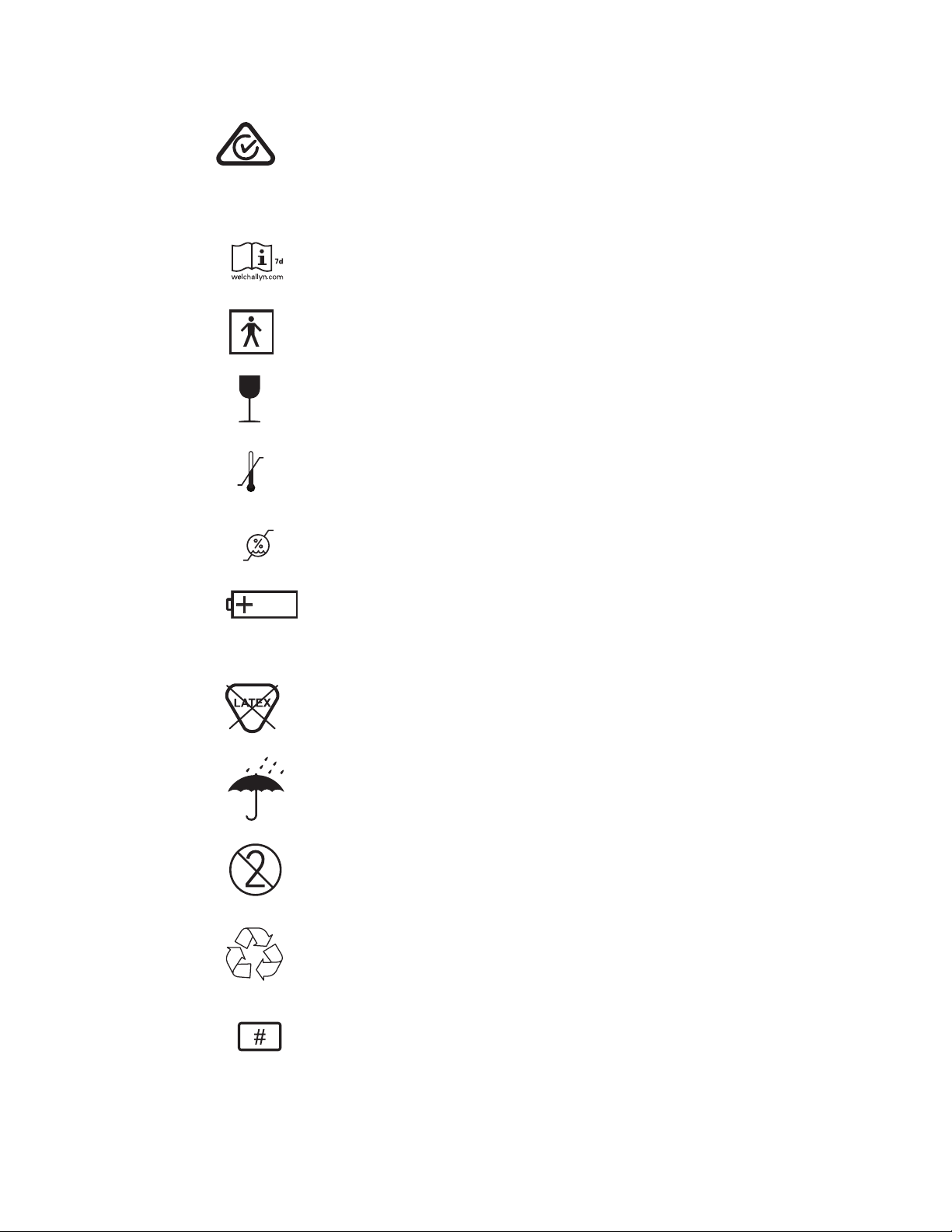
1.4 Symbols and descriptions
Consult directions for use (DFU). A copy of the DFU is available on this
website. A printed copy of the DFU can be ordered from Welch Allyn for
delivery within 7 calendar days.
Type BF Applied Part
Fragile
+
Temperature Limit
-
95%
15%
Humidity Limitation
Internally Powered Alkaline Battery - AA 1.5V
IPXØ Not protected against the ingress of water.
Does not contain natural rubber latex.
Keep Dry
Do not re-use, Single use device
Recyclable
Reorder Number
SureTemp® Plus Service Manual 3
Page 8
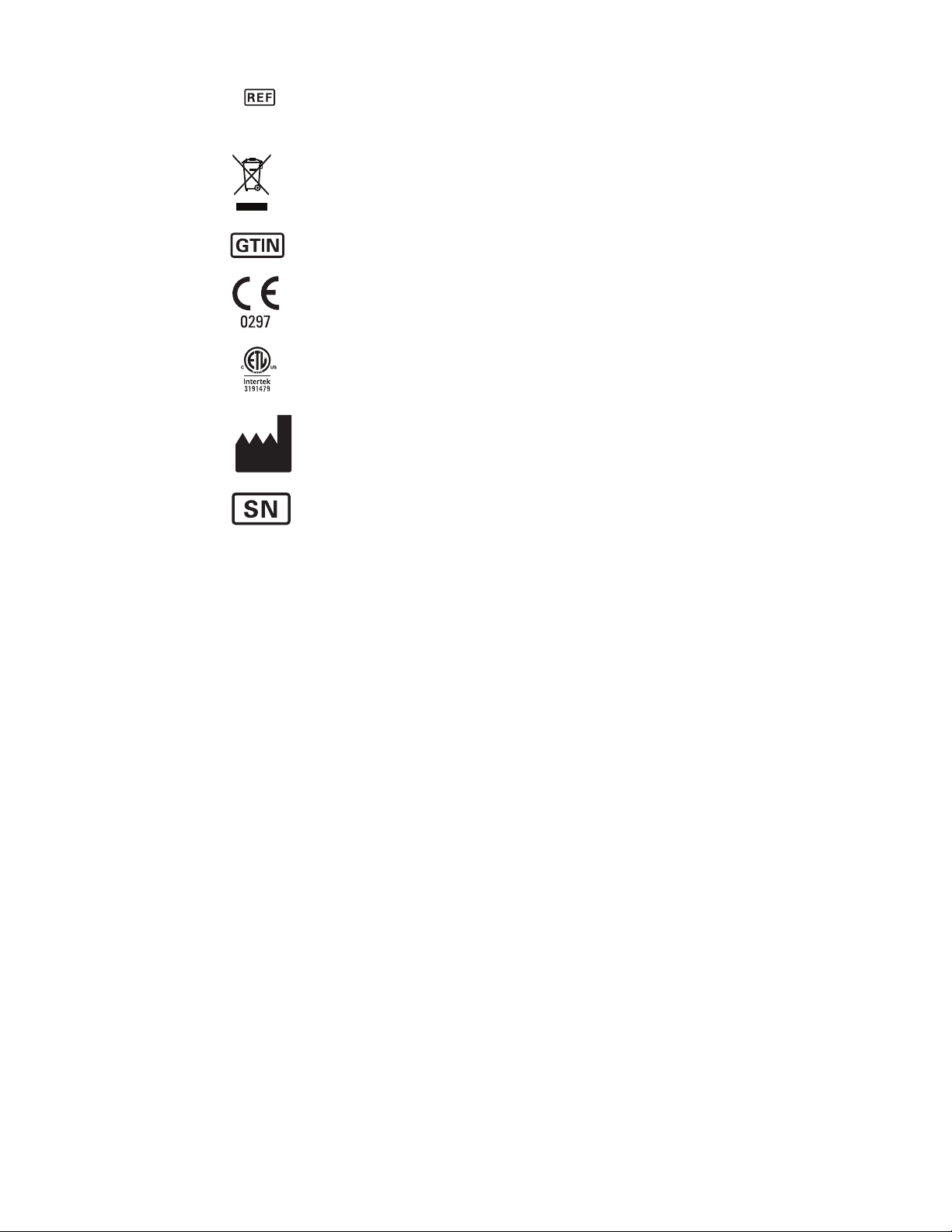
Product Identifier
Separate collection of Electrical and Electronic Equipment. Do not dispose as unsorted municipal waste.
Global Trade Item Number
Meets essential requirements of European Medical Device Directive 93/
42/EEC
Intertek Testing Laboratories Approved (ETL)
Manufacturer
Serial Number
4
Page 9
2. Operating Characteristics
2.1 Basic System Description
The Welch Allyn® SureTemp® Plus Model 690 and 692 thermometers are portable electronic
thermistor thermometers. Users can measure a patient's temperature in the oral, axillary, and
rectal body sites of adult, pediatric, and newborn patients.
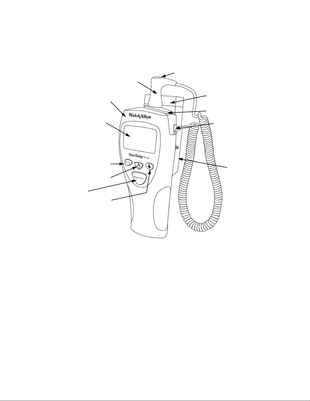
Probe
Probe Cover Ejection Button
Thermometer
LCD Display
Celsius/Fahrenheit Toggle
Button
Pulse Timer Button/Monitor Mode
(692 only)
Recall Button
Mode Selection Button
Box of Probe Covers
Removable Probe Well
Latching Probe
Connector
Battery Door/Probe
Cover Storage
Holder
Figure 1: Model 692 Thermometer
The thermometer consists of six main components: the instrument, the probe, the removable
probe well, the probe cover, the batteries, and the wall mount.
2.1.1 Instrument
The instrument includes a removable probe well and detachable probe.
2.1.2 Probe
The detachable probes are available in short (standard) or long cord versions and include a
mechanical probe cover ejection mechanism, which is triggered by the user through a simple
finger press. The probes are designed for easy exchange in the clinical environment.
• The short (standard) coiled cord probe stretches to approximately 4' and has a retracted
length of approximately 10".
• The long version stretches to approximately 9’ and has a retracted length of approximately
28".
SureTemp® Plus Service Manual 5
Page 10

Four probe types are available and interchangeable on the thermometer:
1. A blue Oral/Axillary probe with a short (standard) coiled cord
2. A red Rectal probe with a short (standard) coiled cord
3. A blue Oral/Axillary probe with a long coiled cord
4. A red Rectal probe with a long coiled cord
2.1.3 Probe well
This unit has a removable probe well to allow for ease of cleaning and replacement. The blue
probe well is used with Oral and Axillary probes, and the red probe well is used with Rectal
probes.
2.1.4 Probe covers
The SureTemp® Plus Thermometers must use the standard Welch Allyn® thermistor probe
covers. The probe covers are compatible across all Welch Allyn® thermistor-based
thermometers.
2.1.5 Batteries
The Model 690 and 692 thermometers use three AA batteries. No battery charging is
available. The thermometer display will indicate when the batteries need replacement.
2.1.6 Wall Mount
The wall holder is easily secured to a wall. A locking mechanism with a removable key for
securing the instrument is standard on the Model 692 Thermometer and is available as an
option for the Model 690. Through the use of available long cord probes, the thermometer may
be used without removing it from the wall holder.
6
Page 11

2.2 Model Features
Features of the SureTemp® Plus Thermometer models (690 and 692) are listed below.
Table 2-1: Feature differences between Models 690 and 692
Feature Model 690 Model 692
Probe Cover Storage
F/C Conversion
Last Temperature Recall
Monitor Mode
Detachable Probe
Oral/Axillary/Rectal Modes on Each
Thermometer
Color-Coded Removable Probe Well
Wall-Holder
Pulse Timer
Backlight
Security (Electronic)
On-Screen Labeling for Instrument
Identification
2.3 Operating Features
2.3.1 Instrument Reset
To perform a reset:
X X
X X
X X
X X
X X
X X
X X
Optional Standard
X
X
X
X
1. Remove the batteries from the instrument to reset the internal microprocessor electronics.
Follow the battery removal instructions in “Replacing the Batteries” on page 16.
2. Remove the probe and the probe well from the instrument. Then, unplug the probe
connector by depressing the locking tab and pulling on the connector body. DO NOT pull
on the cord.
3. While watching the display, install the batteries per the instructions in “Replacing the
Batteries” on page 16 and observe the Power-On Self Test described below.
2.3.2 Power-On Self Test (POST)
The self-test will check the internal microprocessor,
instrument electronics, and display for correct operation.
The instrument performs the self-test series following all
power-on or reset cycles. During the self test sequence the
thermometer displays all LCD segments for 2 seconds.
Concurrently, the thermometer plays the power-on audible
notification and performs necessary self-testing.
Figure 2: Model 690 and 692
Thermometer Displays
SureTemp® Plus Service Manual 7
Page 12

Immediately following the LCD segment test, the software revision is displayed on the screen
for 2 seconds. At the end of the self-test, the display goes blank and the unit is ready to
operate.
2.3.3 Low Power Mode
The Low Power mode allows the thermometer to conserve power when it is not in use.
The unit will automatically enter the Low Power mode following one of these conditions:
1. After a final predicted temperature has been taken, the probe has not been returned to the
well, and the displayed temperature has been on the screen for 30 seconds.
2. When the instrument is in Monitor mode and the probe tip is out of the patient temperature
range (80 F to 110 F) for a period greater than 5 minutes.
3. At the completion of the Recall mode time-out of 5 seconds.
4. Whenever the probe is returned to the well and the probe is plugged into the thermometer.
5. Whenever the probe is unplugged from the thermometer.
6. Whenever the unit is in the Biotech mode and there are no button presses for 5 minutes.
The unit will exit Low Power mode when any button on the instrument is pushed or the probe
switch is activated. When the unit exits Low Power mode after the probe is removed from the
well, all LCD segments are displayed for approximately 2 seconds.
2.3.4 Predict Mode
Predict mode operation is the rapid mode of temperature taking. This is the default mode and
is automatically selected when the probe is withdrawn from the probe well. This mode
provides the clinical user with predictive temperature capability for obtaining oral, rectal,
pediatric axillary (17 years and younger), and adult axillary (18 years and older) temperatures.
If the mode is changed from Predict mode to Monitor mode during normal operation, it will
change back to Predict mode when the probe is returned to the probe well.
1. Upon withdrawal of the probe from its storage well, every segment on the display is
illuminated. The display will then show ORAL, ADULT AXILLARY, PED AXILLARY or
RECTAL, depending on the probe and mode selected. It will also display C or F. In the
upper left hand corner the ID will be displayed if one has been set (Model 692 only), and in
the lower right hand corner the battery icon will be displayed. At the same time that the
mode is displayed, a short beep will sound.
2. To change between the Oral, Adult Axillary, and Pediatric Axillary modes, press and
release the Mode button. Observe that the display changes between ORAL, ADULT
AXILLARY, and PED AXILLARY when the Mode button is pressed and released.
3. When the correct mode has been selected load a probe cover and take a temperature.
Note: It is possible that the walking segments will start and stop several times before the
probe is inserted into the temperature site. This is acceptable and will not adversely
affect the temperature taken.
8
Page 13
2.3.5 Monitor Mode
The Monitor mode provides continuous temperature monitoring capability. The recommended
wait time for a Monitor mode oral temperature and a Monitor mode rectal temperature is 3
minutes. The recommended wait time for a Monitor mode axillary temperature is 5 minutes.
The thermometer will automatically switch to Monitor mode under the following conditions:
1. If 60 seconds have passed since the thermometer was removed from the probe well.
2. If the instrument determines that room temperature is above 34.2C (93.5F).
3. If the thermometer is unable to predict an oral or axillary temperature after 20 seconds due
to improper technique or excessive probe movement.
In the normal Predict mode, with correct use, the patient’s oral temperature is displayed in
approximately 4 seconds. The instrument will beep to signal completion of the Predict mode
temperature cycle.
If the probe is left out of the storage well after completion of a Predict mode temperature, the
unit will shut down after 30 seconds and enter Low Power mode to conserve power. Replace
the probe in the storage well to prepare for the next temperature.
WARNING: Long-term continuous monitoring beyond three to five minutes is not
recommended in any mode.
For Model 692, press and release the Pulse Timer / Monitor Mode button after you have
withdrawn the probe from the probe well to switch the device into Monitor Mode. The Monitor
Mode indicator appears on the LCD.
WARNING: The unit will automatically enter Monitor Mode if the probe is withdrawn
from the probe well and is not replaced within 60 seconds of inactivity.
For Model 690, take the patient’s temperature using the normal Oral, Rectal, Pediatric Axillary,
or Adult Axillary Mode as previously described. Continue to hold the probe in position after the
temperature is displayed. Press the Mode Selection button until the Monitor Mode indicator
appears on the LCD.
SureTemp® Plus Service Manual 9
Page 14

2.3.6 Pulse Timer/ Monitor Mode (Model 692 only)
Pulse Timer mode is activated from Low Power or Recall mode by pressing the Pulse Timer
button. The display will then count up in seconds, and the unit will emit an audio beep at 0, 15,
30, 45 and 60 seconds. Pulse Timer mode terminates automatically after 60 seconds. The
thermometer then returns to Low Power mode. The Pulse Timer can be stopped at any time
during the 0-60 count by pressing the Pulse Timer button a second time. Pressing the Recall
button, connecting a probe, or removing the probe from the probe well will also terminate the
pulse timer.
For Monitor Mode, press and release the Pulse Timer button after you have withdrawn the
probe from the probe well to switch the device into Monitor Mode.
2.3.7 Backlight (Model 692 only)
A backlight is provided by two high-efficiency amber LEDs, each supplied by a separate
ballast resistor. The backlight is turned on automatically in any mode except Low Power mode
and remains on. The backlight will automatically shut off when the unit goes into Low Power
mode.
2.3.8 Horn
The horn is a miniature piezoelectric speaker which produces the audible tones that signal
significant warning events to the user. The following audible signals will be played by the
thermometer.
Table 2- 2: SureTemp® Plus Audible Signals
Signal Description Sound
POWER ON Batteries are inserted in the device. Charge up sound. Sound starts
at a low frequency, increases in
frequency, gets shorter in
duration between each
frequency.
POWER OFF Battery level is too low and the unit
is shutting down.
COMPLETE Successful completion of a predict
temperature or pulse timer.
OK Start of Pulse Timer, Recall or
Monitor mode
OK Auto Monitor mode One long beep
ERROR Final temperature in error or Error
mode
CONFIRM Any button press One medium length beep
PULSE Pulse Timer 15 second sound One quick beep
SECURITY Security State; i.e. device removed
from security holder while security
enabled and instant on = ON
READY When probe is ready to insert into
mouth (not when probe removed
from well).
Charge down sound or losing
power sound. Sound starts at a
high frequency, decreases in
frequency, gets longer durations
between each frequency.
Three quick beeps
Two quick beeps
Two long beeps
Continuous series of beeps
One medium length beep
10
Page 15

2.3.9 F/C Conversion
The temperature switches to F or C scale by pressing and releasing the C/F button. The
default temperature scale can be set to F or C in the biotech mode. A temperature must be
displayed on the screen to switch between F and C.
2.3.10 Temperature Recall
This mode displays the most recently completed predicted temperature.
Whenever the instrument is in Low Power or Pulse Timer mode, pressing and releasing the
Recall button on the front panel will cause the most recently predicted temperature to display
for 5 seconds. The unit will then automatically go into Low Power mode.
Pulling the probe from the well in Recall mode will start a predict cycle. To enter Biotech
mode, hold the Recall button down and then pull the probe from the well. Model 692 units
must be in the wall holder to enter Biotech mode.
Pressing the Pulse Timer button on the Model 692 thermometer will interrupt the temperature
recall function.
Note: No Monitor mode temperatures are saved for recall. When a temperature is recalled,
the mode in which it was obtained (Oral, Adult Axillary, Pediatric Axillary, or Rectal) is
displayed, regardless of the current mode the thermometer is in.
2.3.11 Biotech Mode
This mode is used to set and check special features of the thermometer listed in Table 2-1. All
Biotech mode settings are saved so they are not lost when the batteries are replaced.
1. Place the thermometer in the wall holder (Model 692 Only).
2. Press and hold the Recall button, while removing the probe from the probe well. Once the
probe is removed, release the Recall button.
3. Press and release the Recall button to move sequentially through the various program
categories. Changes within each category are made by pressing and releasing either the
Mode Selection or C/F button.
4. The Biotech mode control settings are stored in nonvolatile memory so that they are not
lost when the batteries are changed. The Biotech mode will automatically time out after 5
minutes of inactivity.
5. Replacing the probe into the probe well at any time will exit the Biotech mode and return
the unit to normal operation.
SureTemp® Plus Service Manual 11
Page 16

The following features and selections are available in the Biotech mode.
Table 2- 3: Biotech Mode Features
Function Setting
DEVICE VERSION The display will show “X.X”, where “X.X” is the device
software version number (i.e. 1.0). This is helpful when
discussing operation with Welch Allyn Customer Care.
ALGORITHM
VERSION
ID
(Model 692 Only)
DEFAULT MODE You may choose between four settings as the default
UNITS DEFAULT This section displays the temperature measurement scale.
SITE INDICATION Three options are available for mode indication: icon and
SECURITY COUNT
(Model 692 Only)
INSTANT ON
(Model 692 Only)
The display should show “X.X” where “X.X” is the mode
Software Version (i.e. 7.5). This is helpful when discussing
operation with Welch Allyn Customer Care.
This section of the display is designed to store up to a
seven digit alpha-numeric thermometer ID. To store the
thermometer's ID, press and release either the Mode or
the C/F button to change the value of the flashing digit.
Press the Pulse Timer button to move to the next digit.
predictive mode: Oral, Adult Axillary, Pediatric Axillary, and
Last (last prediction). To change the default mode, press
and release the C/F button or the Mode Selection button to
advance to the next mode. This setting is retained in nonvolatile memory when the batteries are replaced.
To change the measurement scale from °F to °C, press
and release the C/F button or Mode Selection button. This
setting is retained in non-volatile memory when the
batteries are replaced.
words, words only, and icon only. To change the setting,
press and release the Mode Selection button or C/F button
to advance to the next type of indication. This setting is
retained in non-volatile memory when the batteries are
replaced.
The anti-theft function uses a temperature counter that
can be set at OFF, 25, 50, 100, or 200.
• Press and release the Mode Selection button to select
the desired security count.
• Press and release the C/F button to select descending
security count option (i.e. 200, 100, 50, 25, OFF).
The instrument is set to the selected security count after
the probe is returned to the probe well. This setting is
retained in non-volatile memory when the batteries are
replaced.
The thermometer can be set to alarm when removed
from the wall holder. This alarm can be disabled by the
user by simultaneously pressing the Mode Selection
button while pulling the probe from the probe well.
When this security feature is set to ON and the
thermometer is returned to the wall holder the security
feature is reactivated.
12
To set this security feature, press and release the Mode
Selection button or C/F button to select ON (activated)
or OFF (deactivated). This setting is retained in nonvolatile memory when the batteries are replaced.
Page 17

Table 2- 3: Biotech Mode Features
Function Setting
BATTERY This setting displays the current battery voltage with 10
COUNTER
Predictive Temperature
Counter
ERROR LOG This setting displays the last 10 saved error messages in a
CLEAR LOG This setting appears if the thermometer has logged any
2.4 Instrument Security
Security options include two different electrical security options that alarms after a user
designated number of temperatures is reached or when the unit is removed from the wall
holder (Model 692 only). A mechanical security option is also available to prevent removal of
the unit from the wall mount or mobile stand without a special tool. The design of the
SureTemp® Plus Thermometers allows a facility to apply magnetic or RF security tags to the
unit without adversely affecting the unit’s performance or functionality.
mV resolution. The battery is considered acceptable if it
measures higher than 3.4 volts. A new battery should
produce 4.5 volts or more.
This setting displays the number of predictive temperature
measurements that have been completed (in 100's).
last-in, first-viewed sequence. This is helpful when
discussing operation with Welch Allyn Customer Care. If
there are no error messages, the display shows EMPTY
LOG.
error messages. Press and release the Mode Selection
button to select YES to clear the error log or NO to keep
the entries in the log.
The SureTemp® Plus Model 692 Thermometer has two distinct anti-theft systems available
that are user selectable. Both systems require the use of a holder system with the
thermometer. This setting will be retained in non-volatile memory when the batteries are
replaced.
2.4.1 Temperature Count Security Feature
The Temperature Count security feature allows you to take a set number of temperature
readings before the instrument goes into the security alarm state. The selectable counts are
25, 50, 100, and 200. As the instrument nears the final reading, it will display SECURITY
COUNT as a warning, along with a number representing the last 5 temperature counts (i.e.,
5,4,3,2,1) remaining on the security counter.
When the instrument enters the alarm state, it beeps for approximately 10 seconds. At this
time, the instrument displays SEC on the LCD along with SECURITY COUNT in the ID field in
the upper left-hand corner of the screen. The instrument is then disabled. Returning the
instrument to the wall holder resets the security count. If the count is set to OFF, the
temperature count function is disabled and no security alarm will occur.
This setting is programmable through the Biotech mode (page 11).
2.4.2 Instant-On Security Feature
When the Instant-On security feature is activated, the instrument goes into the security alarm
state within five seconds after removal from the wall holder. When the instrument enters the
alarm state, it beeps continuously and displays SEC on the LCD. Pressing the Mode
SureTemp® Plus Service Manual 13
Page 18

Selection button while removing the probe from the probe well, within 30 seconds of the
instruments removal from the wall holder, clears the alarm and allows the instrument to
operate. Returning the instrument to the wall holder will reset the instant audio alarm.
The options for the Instant-On feature are ON and OFF. In the OFF setting, no security alarm
will sound.
This setting is programmable through the Biotech mode (page 11).
14
Page 19

3. Preventive Maintenance
The following preventive maintenance is recommended to maximize uninterrupted service
with the SureTemp® Plus Model 690 and 692 Thermometers.
3.1 Six-Month Maintenance
Units that are in service on a regular basis should have the following preventive maintenance
performed every six months:
1. Visually inspect the thermometer for any physical damage that might cause future product
failure.
2. Clean the unit per instructions in the Operator’s Manual supplied with the thermometer
and/or per the instructions below.
3.2 Twelve-Month Maintenance
For units in service on a regular basis, perform the Power-On Self Test and Model 9600 or
9600 Plus Calibration Testing procedure every 12 months. The preventive maintenance
procedure is located in the Model 9600 or 9600 Plus Operation Manual.
3.3 Standard Storage
Units which are stored for an extended period should have the following maintenance
performed every 12 months:
1. Remove the batteries before storage.
2. Reinstall the batteries and perform the Power-On Self Test and Model 9600 or 9600 Plus
Calibration Testing procedure found in the Model 9600 or 9600 Plus Operation Manual
before use.
3.4 Cleaning
3.4.1 Cleaning and Disinfection the Thermometer and Probe
Wipe the thermometer and probe with an appropriate health care low- or intermediate-level
cleaner/disinfecting wipe that incorporates either a 1:10 sodium hypochlorite (bleach) solution
or isopropyl alcohol as the active disinfection ingredient. Follow wipe manufacturer's
instructions for appropriate use, contact times and applicable warnings and precautions.
CAUTION: DO NOT immerse or soak the thermometer or probe in any type of fluid.
CAUTION: DO NOT use steam, heat, or gas sterilization on the thermometer or probe.
CAUTION: DO NOT autoclave the thermometer or the probe.
SureTemp® Plus Service Manual 15
Page 20

3.4.2 Cleaning The Removable Probe Well
• Remove the probe well from the unit. Unplug the latching probe connector to prevent the
device from consuming battery power while you are cleaning the probe well.
• Clean the inner surface of the probe well by swabbing the surface with a cloth dampened
with a 1:10 sodium hypochlorite (bleach) solution or isopropyl alcohol solution as the
active disinfection ingredient. Clean the probe well's outer surface by swabbing or wiping
the surface with one of the solutions mentioned above.
CAUTION: DO NOT immerse or soak the thermometer or probe in any type of fluid.
CAUTION: DO NOT use steam, heat, or gas sterilization on the thermometer or probe.
CAUTION: DO NOT autoclave the thermometer or the probe.
• Thoroughly dry all surfaces before re-assembling the instrument.
• Re-connect the latching probe connector to the thermometer. Ensure that the connector
snaps into place.
• Re-install the probe well in the thermometer and snap the probe well into place.
• Insert the probe into the probe well.
3.5 Replacing the Batteries
1. Remove the box of probe covers from the probe cover storage compartment on the back
of the unit.
2. Remove the probe and the probe well.
3. Press inward on the textured grips on each side of the assembly to remove the battery
door from the back of the unit.
4. Remove the three AA 1.5Vdc batteries and replace all three batteries with AA 1.5 Vdc
batteries. Match the +/- polarity of each battery to the +/- symbols inside the battery
compartment.
WARNING: Use size AA 1.5 Vdc batteries only. Use of any other battery size or type could
damage the thermometer and cause personal injury.
5. Snap the probe cover storage assembly back into place.
6. Replace the probe and probe well.
Note: Remove the batteries, if the instrument is not used for an extended period of time, to
avoid possible damage to the thermometer due to battery leakage.
16
Page 21

3.6 Calibration Testing
Whenever the clinical accuracy of the thermometer is in question, verify the instrument
calibration. Your hospital biomedical department should establish a routine schedule for
verifying instrument calibration. It is recommended the unit be tested annually.
3.6.1 Cal-Key Verification
This method uses a fixed value to verify that the device is calibrated properly.
1. Remove any probe currently connected to the SureTemp
2. Connect the SureTemp® Plus Cal-Key (PN 06138-000).
3. Wait one minute for the device to enter Monitor mode and display the temperature.
4. The temperature should read 36.3 +/- 0.1ºC or 97.3 +/- 0.2ºF.
5. Remove the SureTemp® Plus Cal-Key.
6. Connect the original probe back to the device.
®
Plus Thermometer.
3.6.2 Model 9600 Plus Calibration Tester Verification
This method is used to verify the calibration of the unit and probe at three set point
temperatures 36.0ºC (96.8ºF), 38.5ºC (101.3ºF), 41.0ºC (105.8ºF). Use a verified
thermometer from the Cal-Key Verification (3.5.1) and a functioning probe.
CAUTION: Store thermometers for testing in the same room as the 9600 Plus Calibration
Tester for approximately 30 minutes prior to testing to allow for thermal accommodation.
1. Plug in the Model 9600 Plus Calibration Tester wall transformer to electrical power.
2. The 36.0ºC (96.8ºF) temperature setting is selected when the calibration tester is first
powered on.
If the calibration tester is all ready powered on, change the temperature setting on the
Model 9600 Plus Calibration Tester to 36.0ºC (96.8ºF) with the up/down arrow key
(temperature will scroll through the 3 settings).
It is important to use the lower temperature setting first because the stabilization time from
high temperature to low temperature takes about twenty (20) minutes. Stabilization time
from a lower temperature to a higher temperature takes about six (6) minutes.
3. Wait for the displayed temperature to stop blinking. The actual temperature displayed
blinks until the set temperature has stabilized.
4. Remove the probe from the thermometer well and clean it with either a 70% isopropyl
alcohol solution, a 10% chlorine bleach solution, or a non-staining disinfectant. Let the
probe air dry for at least five minutes. Do not apply a probe cover. Place the thermometer
in Monitor Mode. Refer to the thermometer’s Operator’s Manual.
5. Rotate the dust cover down so the Thermistor Device Port is open/available, leaving the
Ear Device Port covered, and insert the probe fully into the small hole on top of the Model
9600 Plus Calibration Tester.
SureTemp® Plus Service Manual 17
Page 22

6. Wait for approximately one minute or until temperature on the thermometer is stable for
ten seconds. Compare the thermometer’s temperature reading to the 9600 Plus’
calibration set point temperature. If the temperatures are within + 0.1ºC (+ 0.2ºF), the
thermometer is within calibration.
7. Remove the probe from the probe well and place back into the thermometer probe well.
8. Test all available thermometers for calibration verification at the current calibration set
point temperature. Proceed to the next calibration set point temperature.
Note: To scroll from one set point to the next, press and hold the temperature selection
button until a beep is heard. The newly selected set point appears in the upper left corner
of the LCD display. The device’s current temperature is displayed, will start to flash, and
continue flashing until the cavity reaches the equilibrium at the new set point.
9. When done testing all thermometers at all temperature set points, close the dust cover on
the Model 9600 Plus Calibration Tester.
18
Page 23
4. Troubleshooting
Verify your Biotech Mode settings (page 11) to verify your device is configured properly.
If the device accuracy is in question, refer to the Calibration section starting on page 17.
If the above two tests do not help or cannot be done, read through the following to help
diagnose the unit.
4.1 Types of Errors
Error indications fall into five major categories.
4.1.1 Battery Indications
Battery error occurs when the instrument detects the following:
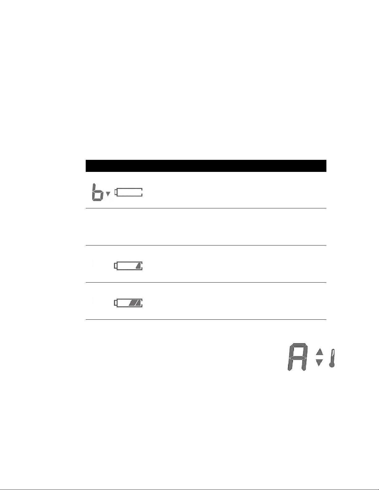
Table 4- 1: Battery Indications
Display Error Indication
Battery below
operational range
(< 3.00v)
Battery above
operational range
(> 5.375v)
Battery Low
Warning
(> 3.0v & <= 3.4v)
Battery levels Gradual decline in number of
Blinking battery frame, b on main
display, arrow pointing down.
Blinking battery frame, b on main
display, arrow pointing up.
Single blinking battery segment in
battery indicator.
segments showing in battery
indicator.
4.1.2 Ambient Temperature Out of Range
Ambient Temperature errors occur when the ambient probe temperature is
above 104.0° F or below 50.0° F. During an ambient temperature error, the
display in the temperature number field shows a capital “A” followed by a
blinking up or down arrow and a blinking thermometer bulb.
19
Page 24

4.1.3 Patient Temperature Out of Range
Patient Temperature Out of Range errors occur when the patient
temperature is above 110.0° F or below 80.0° F. During this error, the
entire body (head, torso, and legs) displays by blinking with a solid up or
down arrow and a thermometer bulb.
4.1.4 Probe Errors
The probe or probe connector can generate errors. Probe errors are
displayed as a probe with an X through it and an error code in the
temperature field. In most cases this will represent a broken probe that
needs replacing and the code will tell what error was detected.
Temperature measuring is prohibited until the error is cleared.
4.1.5 Instrument Errors
Instrument Circuitry errors are generated from internal test failures.
Instrument errors are displayed as an instrument with an X through it and an
error code in the temperature field. In most cases this will represent a broken
instrument that needs replacing and the code will tell what error was
detected. Error code numbers are available in Biotech mode under Error Log
(see page 11).
20 Sure Temp® Plus Service Manual
Page 25

4.1.6 Error Codes: Troubleshooting
The following table describes the error codes displayed on the thermometer, their
corresponding descriptions, and the actions to take to correct the error. If the unit fails to
operate properly after completing the suggested procedure listed in the following table, contact
Welch Allyn® Customer Care at 1-800-535-6663.
Table 4- 2: Error Codes: Troubleshooting
Error
Code
E0.1 Excessive Heater Energy Try another predict cycle.
E0.2 A/D Measurement out of
E0.4 Probe Over Temperature
E0.5 No Probe Temperature
E0.6 Probe EEPROM read
E0.7 Probe EEPROM is
E0.8 EEPROM CRC Failure
E0.9 Bad probe calibration. Replace with a calibrated probe.
E4.0 PTB measurement out of
E4.1 RCAL measurement out of
E4.2 Reference power supply
E4.3 Device EEPROM save
Description Troubleshooting Steps
If the problem persists replace the
probe or contact Welch Allyn
Customer Care.
Make sure the temperature is within
range error.
(110ºF/43.3ºC)
Rise. (The heater has no
effect.)
failure. (Bad EEPROM
handshake.)
un-initialized.
(EEPROM is corrupted.)
range.
range.
malfunction.
failure.
the operating range of 50ºF/10ºC and
104ºF/40ºC
If the problem persists replace the
probe or contact Welch Allyn
Customer Care.
Make sure the tip temperature is
below 110ºF/43.3ºC.
If the problem persists replace the
probe or contact Welch Allyn
Customer Care.
Try another predict cycle.
If the problem persists replace the
probe or contact Welch Allyn
Customer Care.
Verify the batteries are fresh.
If the problem persists replace the
probe.
Verify that the batteries are fresh.
If the problem persists replace the
probe.
Verify that the batteries are fresh.
If the problem persists contact Welch
Allyn Customer Care.
Try another predict cycle.
If the problem persists contact Welch
Allyn Customer Care.
Try another predict cycle.
If the problem persists contact Welch
Allyn Customer Care.
If the problem persists contact Welch
Allyn Customer Care.
Verify that the batteries are fresh.
If the problem persists contact Welch
Allyn Customer Care.
21
Page 26

Table 4- 2: Error Codes: Troubleshooting
Error
Code
Description Troubleshooting Steps
E4.4 Device EEPROM starting
handshake failure.
E4.5 Device EEPROM response
failure.
E4.6 Transmit failure to the
Device EEPROM.
E4.7 Can’t initialize the device
EEPROM
E4.8 Device was not calibrated Replace the device with a calibrated
E5.0 Heater is not working
properly.
E5.2 Heater fail-safe failure. Contact Welch Allyn Customer Care.
23 Host Interface Error Try another predict cycle.
26 Invalid SureTemp mode Try another predict cycle.
29 Battery Voltage Is Not Set Try another predict cycle.
30 Prediction mode Is Not Set Try another predict cycle.
71 Device EEPROM acquire
failure
72 Device EEPROM release
failure
73 DEVICES EEPROM invalid
pointer failure.
b^ Battery voltage too high. Replace the batteries with batteries
bv Battery voltage too low. Replace the batteries with new
Verify that the batteries are fresh.
If the problem persists contact Welch
Allyn Customer Care.
Verify that the batteries are fresh.
If the problem persists contact Welch
Allyn Customer Care.
Verify that the batteries are fresh.
If the problem persists contact Welch
Allyn Customer Care.
If the problem persists contact Welch
Allyn Customer Care.
device.
Try another cycle.
If the problem persists contact Welch
Allyn Customer Care.
If the problem persists contact Welch
Allyn Customer Care.
If the problem persists contact Welch
Allyn Customer Care.
If the problem persists contact Welch
Allyn Customer Care.
If the problem persists contact Welch
Allyn Customer Care.
Try another predict cycle.
If the problem persists contact Welch
Allyn Customer Care.
Try another predict cycle.
If the problem persists contact Welch
Allyn Customer Care.
Try another predict cycle.
If the problem persists contact Welch
Allyn Customer Care.
that provide less then 5.50 volts to
the SureTemp® Plus.
batteries.
If problem does not go away and the
batteries are known as good (>= 3.1
volts applied) contact Welch Allyn
Customer Care.
22 Sure Temp® Plus Service Manual
Page 27

Table 4- 2: Error Codes: Troubleshooting
Error
Code
Description Troubleshooting Steps
A^! Ambient temperature too
high.
Av! Ambient temperature too
low.
Patient Temperature out of
range. < 80ºF/26.7ºC or >
110ºF/43.3ºC
Move into an area where the
temperature is between 50ºF/10ºC
and 110ºF/43.3ºC and allow the
thermometer to stabilize to ambient
temperature.
If problem persists replace the probe
or contact Welch Allyn Customer
Care.
Move into an area where the
temperature is between 50ºF/10ºC
and 110ºF/43.3ºC.
If the problem persists replace the
probe or contact Welch Allyn
Customer Care.
Make sure the probe is positioned
properly within the patient body site,
with good tissue contact, and/or
verify the patient's temperature is in
the range.
Try another temperature cycle with
the probe positioned properly.
If the problem persists, replace the
probe or contact Welch Allyn
Customer Care.
Note: If your thermometer is within the warranty period, you should return the unit to an
authorized service representative for servicing. Failure to do so will invalidate the
warranty.
23
Page 28

4.2 Field Serviceable Repairs
The only operations that are performed by field personnel are calibration verification, probe or
probe well replacement, battery replacement, and unit replacement.
4.3 Field Serviceable Parts
The following parts are serviceable by qualified technicians.
Note: The following parts list is current as of the date of publication. Parts and part numbers
may change without notice. Check with Welch-Allyn® Customer Care prior to ordering
parts to verify you have current part number information.
Note: If the device fails during the warranty period, please refer to the table for field
replacement parts. If the device fails outside of the warranty period, contact the Welch
Allyn Customer Care team.
Table 4- 3: Field Serviceable Parts
Part # Description
01802-110 9600 Plus Calibration Tester
02891-000 Removable Probe Well (Blue)
02891-100 Removable Probe Well (Red)
02892-000 Probe and Well Kit (Incl. Probe) 4 ' Rectal
02892-003 Probe and Well Kit, 4’, Vet
02892-100 Probe and Well Kit (Incl. Probe) 9 ' Rectal
02892-103 Probe and Well Kit, 9’, Vet
02893-000 Probe and Well Kit (Incl. Probe) 4 ' Oral
02893-100 Probe and Well Kit (Incl. Probe) 9 ' Oral
05031-750 Disposable Probe Covers - 7500/Case
01690-000 PKG THERM SYS, M690 Unit (Probe & Well-
01692-000 PKG THERM SYS, M692 Unit (Probe & Well
53009-00 Batteries AA Alkaline
725525 HOUSING,BATTERY DOOR,M690_692
06138-000 SureTemp® Calibration Key
106701 Operators Manual (DFU)
406682 Soft Carrying Case
sold separately)
sold separately)
24 Sure Temp® Plus Service Manual
Page 29
5. Theory of Operation
5.1 Technical Overview
The SureTemp® Plus Model 690 and 692 are portable, battery powered thermistor-based
medical grade thermometers that perform oral, axillary, and rectal measurements using highspeed prediction modes.
The devices perform a power-on self test (POST) when battery power is applied. POST
checks the internal hardware, and tests the stored calibration values to verify that the factory
calibration is intact. When a thermometer probe is connected, the device reads data from the
probe to determine the type of probe and probe calibration values. The thermometer will go
into Low Power mode when inactive to maximize battery life.
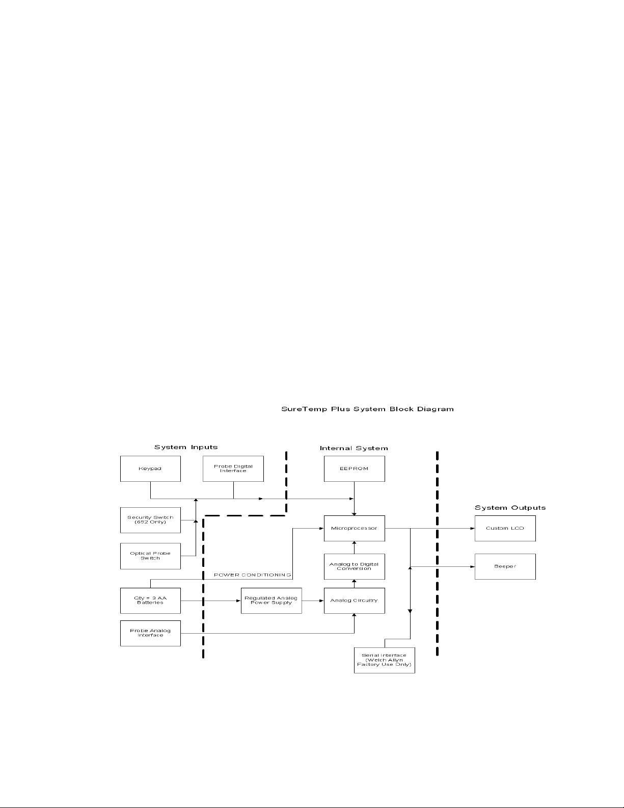
A predict measurement cycle is initiated when a connected thermometer probe is pulled from
the probe well of the device. When the probe is pulled from the probe well the optical probe
detection switch wakes up the microprocessor and a measurement cycle begins. The device
pre-heats the probe tip (Oral and Axillary only) to create a stable thermal environment at the
probe tip. When the tip is applied to the patient the tip heater is turned off. The thermistor value
is monitored by the microprocessor and other internal circuitry. The microprocessor uses
internal modes to process the thermistor data and calculate a patient’s temperature. The
temperature data is then displayed to the user on the LCD. It is also possible to switch the
thermometer to Monitor mode, which displays real-time data from the thermistor.
The Model 692 thermometer includes a backlit LCD for viewing in low ambient light conditions
and a security mode that disables device operation when used outside the programmed
security parameters.
Figure 3: Model 690 and 692 Thermometers System Block Diagram
25
Page 30

5.1.1 Temperature Probes
Model 690 and 692 Thermometer probes are configured at the factory to be Oral/Axillary or
Rectal probe types.
The probe contains a thermistor, a heater resistor, and an EEPROM
Table 5- 1: Probe Parts
.
Probe
Part
Thermistor The Thermistor is used to sense patient temperature.
Heat Resis-
tor
EEPROM
Description
The heater is used to create a stable thermal environment at
the tip of the probe prior to applying the tip to the patient.
During calibration, the I2C SDA line is accessed via the probe
connector and SCL by a special probe connection that does not
connect to the thermometer. The thermometer reads the
EEPROM via its 2-wire serial-only (VESA DDC1) interface. The
interface is guaranteed to work with VCC of 2.7 to 5.25 volts.
5.1.2 Probe Switch
The probe switch is an optical LED switch. It is arranged as an open circuit when the probe is
in the well, to save power. This causes a High-to-Low transition when the probe is pulled.
5.1.3 Power Supply
Power for the Model 690 and 692 is drawn from the three AA cells directly to the circuit
electronics, providing a peak voltage of 4.8V and an average voltage of 3.60 V. Under normal
use, battery life is expected to provide approximately 5,000 temperature measurements for
Model 692, and 6,000 temperature measurements for Model 690. This number is based on a
22.2 ºC (72.0 F) ambient temperature, with the security features turned off. Colder ambient
temperatures, excessive security alarms, and other usage patterns can reduce battery life.
Instruments are shipped with fresh batteries, but we cannot guarantee full life from the first set
of batteries due to potential long storage times between shipping and actual use. Battery life is
also reduced by storage at elevated temperatures.
The battery holder is interlocked to prevent reverse polarity. This is an important aspect of safe
operation of the unit.
5.1.4 Low Battery Detection
The Model 690 and 692 Thermometers include a low battery detector circuit, which shuts the
device off when the battery degrades below 3 volts. This ensures that erroneous temperature
readings are not given due to a low battery.
5.1.5 Temperature Measurement and Display
The thermometer probes incorporate negative temperature coefficient thermistors. When the
temperature of the probe is increased, its electrical resistance decreases.
Model 690 and 692 Thermometers use 20K thermistors, providing a resistance of
approximately 20 K at room temperature. At 37°C (patient temperatures) they are near 12
K. The change in resistance is nonlinear with temperature and an equation describing this
curve is programmed into the thermometer.
26 Sure Temp® Plus Service Manual
Page 31

Appendix A Specifications
Ambient Operating Temperature Range 50.0 F to 104.0 F (10.0 C to 40.0C)
Operating Altitude -557 ft. to +16,000 ft / -170m to +4877m
Patient Temperature Range 80.0 F to 110.0 F (26.7 C to 43.3 C)
Temperature Predict Time* Oral:
Approximately 4–6 secs.
Adult axillary (18 years and older):
Approximately 12–15 secs.
Pediatric axillary (17 years and younger):
Approximately 10–13 secs.
Rectal:
Approximately 10–13 secs.
Transport/Storage Temperature -13°F to +131°F (-25°C to +55°C)
Calibration Accuracy +/- 0.2 F (0.1 C) (Monitor Mode)
Humidity 15% to 95% non-condensing
Dimensions 8.46” x 3.18” x 2.43”
(215mm x 81mm x 62mm)
Weight 12.6 ounces/357 grams
Power (3) 1.5Vdc AA batteries
Equipment Classification Internally powered device, Continuous Opera-
tion
Not AP or APG equipment
IPXØ Not protected against the ingress of water.
* Predict time depends on probe placement and patient condition. Predict times do not include
tissue contact-detection time or time needed to place the probe into the measurement site.
A
Page 32

Appendix B Limited Warranty
THREE-YEAR LIMITED WARRANTY ON MODEL 692 AND TWO-YEAR
LIMITED WARRANTY ON MODEL 690 INSTRUMENTS
Instrumentation purchased new from Welch Allyn, Inc. (Welch Allyn) is warranted to be free
from original defects in material and workmanship under normal use and service for a period
of three years for Model 692 and a period of two years for Model 690 from the date of first
shipment from Welch Allyn. This warranty shall be fulfilled by Welch Allyn or its authorized
representative repairing or replacing at Welch Allyn’s discretion, any such defect, free of
charge for parts and labor.
Welch Allyn must be notified via telephone of any defective product and the item must be
immediately returned, with an RMA number provided by Welch Allyn, securely packaged and
postage prepaid to Welch Allyn. Loss or damage in shipment shall be at the purchaser’s risk.
Welch Allyn will not be responsible for loss associated with the use of any Welch Allyn product
that (1) has had the serial number defaced, (2) has been repaired by anyone other than an
authorized Welch Allyn Service Representative, (3) has been altered, (4) has been used in a
manner other than in accordance with the instructions, or (5) has been abused or exposed to
extreme environmental conditions.
ONE-YEAR LIMITED WARRANTY ON PROBES AND PROBE COVERS
Welch Allyn warrants probes and probe covers to meet Welch Allyn’s specifications for the
Product at the time of purchase and to be free from original defects in material and
workmanship under normal use and service for a period equal to one-year from the date of
first shipment of such Product to the customer by or on behalf of Distributor. Probe covers are
intended for single use only.
NINETY DAY LIMITED WARRANTY ON REMOVABLE PROBE WELLS
Removable probe wells (blue oral and red rectal) are warranted to be free from original defects
in material and workmanship under normal use and service for a period of ninety days from
the date of first shipment from Welch Allyn.
THIS WARRANTY IS EXCLUSIVE AND IN LIEU OF ANY IMPLIED WARRANTY OR
MERCHANTABILITY, FITNESS FOR PARTICULAR PURPOSE, OR OTHER WARRANTY OF
QUALITY, WHETHER EXPRESSED OR IMPLIED. WELCH ALLYN WILL NOT BE LIABLE
FOR ANY INCIDENTAL OR CONSEQUENTIAL DAMAGES RESULTING FROM THE SALE,
USE, OR IMPROPER FUNCTIONING OF THE INSTRUMENTATION REGARDLESS OF
THE CAUSE. THE DAMAGES FOR WHICH WELCH ALLYN WILL BE RESPONSIBLE
INCLUDE, BUT ARE NOT LIMITED TO, LOSS OF REVENUE OR PROFIT, DOWNTIME
COSTS, AND LOSS OF USE OF THE INSTRUMENTATION.
B Sure Temp® Plus Service Manual
Page 33

Appendix C Guidance and Manufacturer’s Declaration
EMC compliance
Special precautions concerning electromagnetic compatibility (EMC) must be taken for all
medical electrical equipment. This device complies with IEC EN 60601-1-2:2014.
• All medical electrical equipment must be installed and put into service in accordance with
the EMC information provided in this document and the Welch Allyn SureTemp Plus
Directions for Use.
• Portable and mobile RF communications equipment can affect the behavior of medical
electrical equipment.
The SureTemp Plus complies with all applicable and required standards for electromagnetic
interference.
• It does not normally affect nearby equipment and devices.
• It is not normally affected by nearby equipment and devices.
• It is not safe to operate the SureTemp Plus in the presence of high-frequency surgical
equipment.
• However, it is good practice to avoid using the SureTemp Plus in extremely close
proximity to other equipment.
Note
The SureTemp Plus has essential performance requirements associated with
temperature measurement. In the presence of EM disturbances, the device might
display an error code. Once the EM disturbances stop, the SureTemp Plus will selfrecover and perform as intended.
WARNING Avoid using the SureTemp Plus adjacent to or stacked with other
equipment or medical electrical systems because it could result in improper
operation. If such use is necessary, observe the SureTemp Plus and other
equipment to verify that they are operating normally.
WARNING Use only accessories recommended by Welch Allyn for use with the
SureTemp Plus. Accessories not recommended by Welch Allyn might affect the
EMC emissions or immunity.
WARNING Maintain minimum separation distance between the SureTemp Plus
and portable RF communication equipment. SureTemp Plus performance might
degrade if you do not maintain a proper distance between equipment.
WARNING This device has not been tested for use in clinical environments near
high-frequency surgical equipment and magnetic resonance imaging. Do not use
this device in environments like these where electromagnetic disturbance is high.
C
Page 34

Emissions and Immunity Information
Electromagnetic Emissions
The Welch Allyn SureTemp Plus is intended for use in the electromagnetic environment specified below.
The customer or the user of the Welch Allyn thermometer should assure that it is used in such an environment.
Emissions Test Compliance Electromagnetic Environment - Guidance
RF emissions
CISPR 11
RF emissions
CISPR 11
Harmonic emis-
sions
IEC 61000-3-2
Voltage fluctua-
tions/flicker emissions
IEC 61000-3-3
Group 1
Class B
Class A
Complies
The SureTemp Plus uses RF energy only for its internal function.
Therefore, its RF emissions are very low and are not likely to
cause any interference in nearby electronic equipment.
The SureTemp Plus is suitable for use in all establishments
other than domestic, and may be used in domestic establishments and those directly connected to the public low-voltage
power supply network that supplies buildings used for domestic
purposes, provided the following warning is heeded:
WARNING: This equipment/system is intended for use by
healthcare professionals only. This equipment/system may
cause radio interference or may disrupt the operation of nearby
equipment. It may be necessary to take mitigation measures,
such as re-orienting or relocating the device or shielding the
location.
D Sure Temp® Plus Service Manual
Page 35

Electromagnetic Immunity
The Welch Allyn SureTemp Plus is intended for use in the electromagnetic environment specified below.
The customer or user of the Welch Allyn thermometer should assure that it is used in such an environment.
Immunity Test
Electrostatic discharge (ESD)
IEC 61000-4-2
Electrical fast
transient/burst
IEC 61000-4-4
Surge
IEC 61000-4-5
IEC 60601 Test
Level
± 8 kV contact
± 15 kV air
±2 kV for power
supply lines
±1 kV for input/
output lines
±1 kV differential
mode
±1 and ±2 kV
common mode
<0% UT
(>100% dip in UT)
Compliance
Level
± 8 kV contact
± 15 kV air
±2 kV for power
supply lines
±1 kV for input/
output lines
±1 kV differential
mode
±1 and ±2 kV
common mode
<0% UT
(>100% dip in UT)
Electromagnetic Environment - Guidance
Floors should be wood, concrete, or ceramic
tile. If floors are covered with synthetic material, the relative humidity should be at least
30%.
Not Applicable - Battery powered Device
Not Applicable - Battery powered Device
Voltage dips,
short interruptions, and voltage
variations on
power supply
input lines.
IEC 61000-4-11
for 1 cycle
70% UT
(30% dip in UT)
for 25/30 cycles
<0 % UT
(>100 % drop in
UT)
for .5 cycles@0°,
45°, 90°, 135°,
180°, 225°, 270°,
& 315° for 250/
300 cycles.
for 1 cycle
70% UT
(30% dip in UT)
for 25/30 cycles
Not Applicable - Battery powered Device
<0 % UT
(>100% drop in
UT)
for .5 cycles@0°,
45°, 90°, 135°,
180°, 225°, 270°,
& 315° for 250/
300 cycles.
E
Page 36

Power frequency
(50/60Hz) mag-
netic field
IEC 61000-4-8
Note: U
is the a.c. mains voltage prior to application of the test level.
T
30 A/m 30 A/m
Power frequency magnetic fields should be at
levels characteristic of a typical location in a
typical commercial or hospital environment.
F Sure Temp® Plus Service Manual
Page 37
Electromagnetic Immunity
The Welch Allyn SureTemp Plus is intended for use in the electromagnetic environment specified below.
The customer or user of the Welch Allyn thermometer should assure that it is used in such an environment.
Immunity
Test
Conducted
RF
IEC 610004-6
IEC 60601
Test Level
3 Vrms
150 kHz to 80 MHz
Compliance
Level
3 Vrms
Electromagnetic Environment - Guidance
Portable and mobile RF communications equipment
should be used no closer to any part of the Welch
Allyn SureTemp Plus models 690 and 692, including
cables, than the recommended separation distance
calculated from the equation applicable to the frequency of the transmitter.
Recommended separation distance
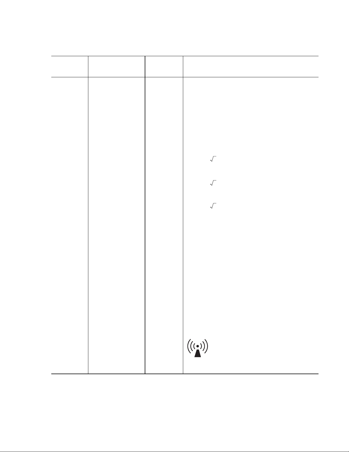
d = (1.17) P
d = (1.17) P 80 MHz to 800 MHz
d = (2.33) P 800 MHz to 2.5 GHz
Radiated RF
IEC 61000-
4-3
3 V/m
80 MHz to 1 GHz
3 V/m
where P is the maximum output power rating of the
transmitter in watts (W) according to the transmitter
manufacturer and d is the recommended separation
distance in metres (m).
Field strengths from fixed RF transmitters, as determined by an electromagnetic site survey,a should be
less than the compliance level in each frequency
b
range.
Interference may occur in the vicinity of equipment
marked with the following symbol:
G
Page 38

Note 1: At 80 MHz and 800 MHz, the higher frequency range applies.
Note 2: These guidelines may not apply in all situations. Electromagnetic propagation is affected by
absorption and reflection from structures, objects, and people.
a
Field strengths from fixed transmitters, such as base stations for radio (cellular/cordless) telephones
and land mobile radios, amateur radio, AM and FM radio broadcast and TV broadcast cannot be predicted theoretically with accuracy. To assess the electromagnetic environment due to fixed RF transmitters, an electromagnetic site survey should be considered. If the measured field strength in the location in
which the device is used exceeds the applicable RF compliance level above, the device should be
observed to verify normal operation. If abnormal performance is observed, additional measures may be
necessary, such as reorienting or relocating the device.
b
Over the frequency range 150 kHz to 80 MHz, field strengths should be less than 3 V/m.
Recommended separation distances between portable and mobile RF communications equip-
ment and the Welch Allyn SureTemp Plus
The device is intended for use in an electromagnetic environment in which radiated RF disturbances are
controlled. The customer or user of the Welch Allyn thermometer can help prevent electromagnetic interference by maintaining a minimum distance between portable and mobile RF communications equipment
(transmitters) and the device as recommended below, according to the maximum output power of the
communications equipment.
Separation distance according to frequency of transmitter (m)
Rated maximum
150 kHz to 80 MHz
80 MHz to 800 MHz
800 MHz to 2.5 GHz
output power of
transmitter (W)
d = (1.17) P
d = (1.17) P
d = (2.33) P
0.01 0.11667 0.11667 0.23333
0.1 0.36894 0.36894 0.73785
1 1.1667 1.1667 2.3333
10 3.6894 3.6894 7.3785
100 11.667 11.667 23.3333
For transmitters rated at a maximum output power not listed above, the recommended separation distance d in meters (m) can be estimated using the equation applicable to the frequency of the transmitter,
where P is the maximum output power rating of the transmitter in watts (W) according to the transmitter
manufacturer.
Note 1: At 80 MHz and 800 MHz, the separation distance for the higher frequency range applies.
Note 2: These guidelines may not apply in all situations. Electromagnetic propagation is affected by
absorption and reflection from structures, objects, and people.
H Sure Temp® Plus Service Manual
Page 39

Page 40

4341 State Street Road
Skaneateles Falls, NY 13153
Tel: +1 800 535 6663
Fax: +1 315 685 3361
www.welchallyn.com
 Loading...