

Page 1
STARTUP
GUIDE
FOR SAFETY AND EASE OF ASSEMBLY, FOLLOW THESE
INSTRUCTIONS STEP BY STEP.
Do not remove packing material from the wall system until the
instructions tell you to do so.
Install the security screw as instructed.
GUÍA DE
INICIO
POR RAZONES DE SEGURIDAD Y PARA FACILITAR EL MONTAJE
DEBE SEGUIR ESTAS INSTRUCCIONES PASO A PASO.
No retire el material de embalaje del sistema de pared hasta que las
instrucciones no se lo indiquen.
Instale el tornillo de seguridad tal y como se indica.
GUIDE DE
DÉMARRAGE
POUR VOTRE SÉCURITÉ ET POUR FACILITER L’ASSEMBLAGE,
VEUILLEZ SUIVRE CES INSTRUCTION ÉTAPE PAR ÉTAPE.
Ne retirez pas le matériel d’emballage du système mural avant que les
instructions ne le stipulent.
Installez les vis de fixation tel qu’indiqué.
Page 2

Page 3
®
Welch Allyn Connex
Integrated Wall System
Startup guide
Page 4

Welch Allyn Connex® Integrated Wall System
© 2011 Welch Allyn. All rights are reserved. To support the intended use of the product described in this publication, the purchaser of
the product is permitted to copy this publication, for internal distribution only, from the media provided by Welch Allyn. No other use,
reproduction, or distribution of this publication, or any part of it, is permitted without written permission from Welch Allyn. We lch
Allyn assumes no responsibility for any injury to anyone, or for any illegal or improper use of the product, that may result from failure
to use this product in accordance with the instructions, cautions, warnings, or statement of intended use published in this guide.
Welch Allyn, Connex, and SureTemp are registered trademarks of Welch Allyn.
SureBP Technology, Vital Signs Monitor 6000 Series, and OptiSense are trademarks of Welch Allyn.
LNCS and Rainbow are trademarks of, and SET, LNOP, and Masimo are registered trademarks of, Masimo Corporation. Possession or
purchase of a Masimo SpO2-equipped device does not convey any express or implied license to use the device with unauthorized
sensors or cables which would, alone or in combination with this device, fall within the scope of one or more of the patents relating
to this device.
Nellcor and OxiMax are trademarks of Nellcor Puritan Bennett Inc.
Braun and ThermoScan are registered trademarks of Braun GmbH.
Software in this product is Copyright 2010 Welch Allyn or its vendors. All rights are reserved. The software is protected by United
States of America copyright laws and international treaty provisions applicable worldwide. Under such laws, the licensee is entitled
to use the copy of the software incorporated with this instrument as intended in the operation of the product in which it is
embedded. The software may not be copied, decompiled, reverse-engineered, disassembled, or otherwise reduced to
humanperceivable form. This is not a sale of the software or any copy of the software; all right, title, and ownership of the software
remain with Welch Allyn or its vendors.
For information about any Welch Allyn product, call Welch Allyn Technical Support
USA + 1 800 535 6663
Canada + 1 800 561 8797 China + 86 216 327 9631
European Call Center + 353 46 90 67790 France + 33 155 69 58 49
Germany + 49 695 098 5132 Italy + 39 026 968 2425
Japan + 81 42 703 6084 Latin America + 1 305 669 9003
Malaysia + 603 7875 3341 Netherlands + 31 202 061 360
Singapore + 65 6419 8100 South Africa + 27 11 777 7555
Spain + 34 917 499 357 Sweden + 46 85 853 6551
United Kingdom + 44 20 7365 6780
+ 1 315 685 4560
Australia + 61 2 9638 3000
::
Material Number 717559, 80016505 Ver. C
Welch Allyn, Inc.
4341 State Street Road
Skaneateles Falls, NY 13153-0220 USA
www.welchallyn.com
Regulatory Affairs Representative
Welch Allyn Limited
Navan Business Park
Dublin Road
Navan, County Meath
Republic of Ireland
Page 5
1
Note
Setup
Caution Welch Allyn is not responsible for the integrity of any wall mounting
interface. Welch Allyn recommends that you contact your Biomedical
Engineering Department or maintenance service to ensure professional
installation, safety, and reliability of any mounting accessory.
Some product features described in this publication might not be available in your
country. For the latest information about products and features, please call Welch
Allyn Customer Care.
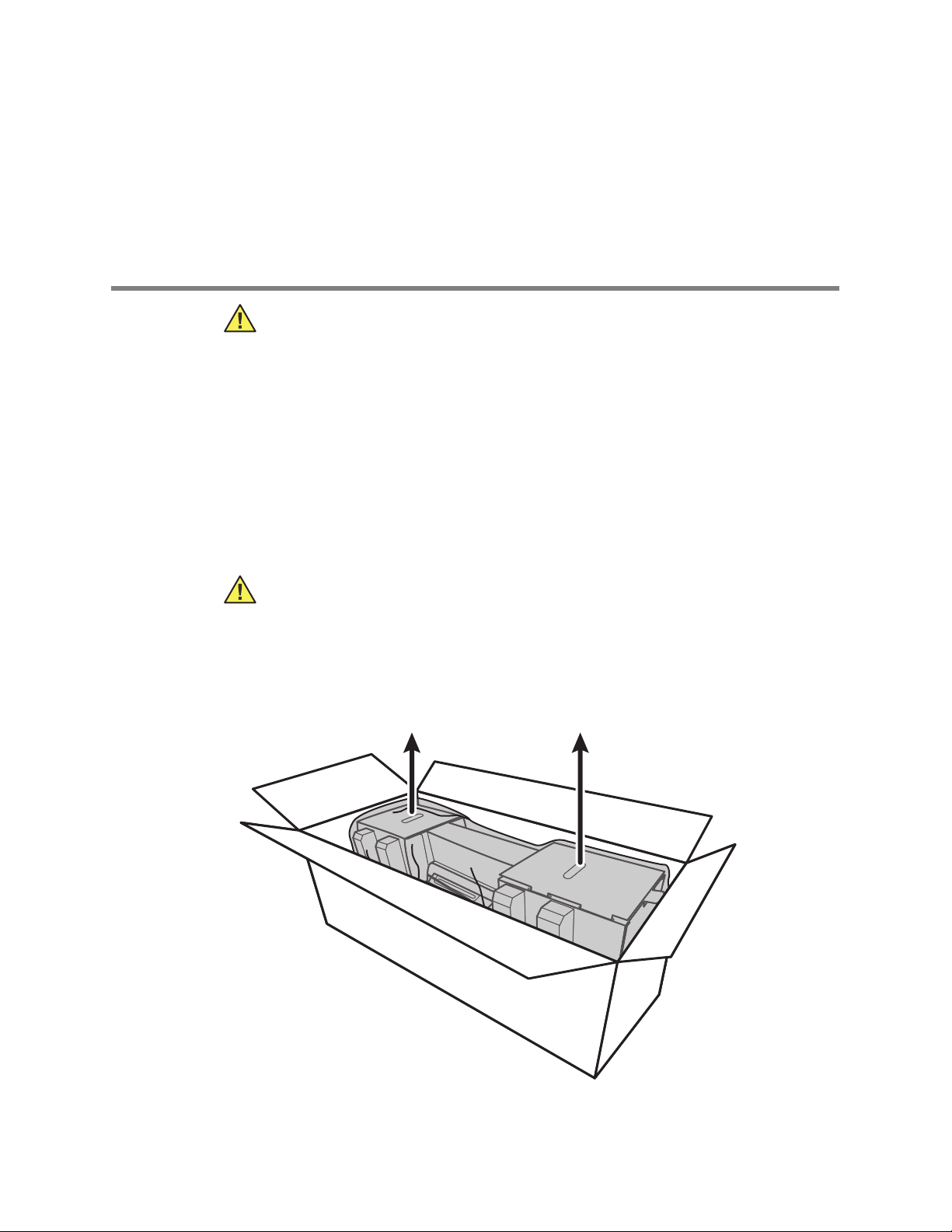
Unpack the wall system
1
This procedure applies to first-time setup of the wall system.
Caution You must follow these instructions exactly to ensure safety and ease of
assembly.
Caution Do not remove any packing materials around the wall system until the
instructions tell you to do so.
1. Lift the wall system out of the box by the cardboard handles.
Page 6
2 Setup Welch Allyn Connex® Integrated Wall System
2. With the wall system still in its packing material, place it onto a table or flat work
surface and remove it from the plastic bag.
3. Turn the wall system over so that the back of the wall system faces up.
Page 7
Startup guide Setup 3
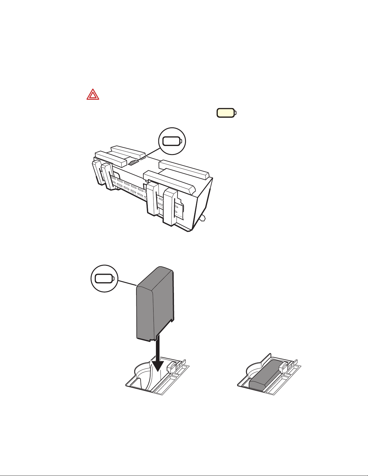
Insert the battery
This procedure applies to first-time setup of the wall system. Therefore, the wall system
is assumed to be shut down.
WARNING Risk of fire, explosion, and burns. Do not short-circuit, crush,
incinerate, or disassemble the battery pack.
1. Locate the battery compartment, indicated by .
2. Insert the battery. (The battery is in a pink anti-static bag in the accessory box.)
Page 8

4 Setup Welch Allyn Connex® Integrated Wall System
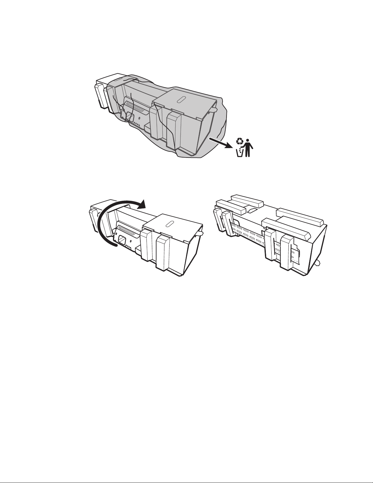
Prepare for mounting
1. Slide the mounting rail bracket out of the packing material and put it aside. Do not
discard. Then flip the wall system onto its back.
2. Remove the cardboard end caps as shown and put aside for recycling.
1
Caution Do not remove the cardboard securing the handles on the left side of
the wall system at this time. The cardboard prevents damage to those
instruments during the mounting process.
Page 9

Startup guide Setup 5
• Mounting rail bracket
• Accessory bin bracket
• Screws
1. Connex Integrated Wall System
2. Examination table
Sample room layout
Mounting hardware inventory
Use these items to mount the wall system.
Tools list
Use these tools to mount the wall system.
• #2 Phillips screwdriver
•level
• tape measure
• stud finder
• drill
• 1/8-inch (3.17 mm) diameter drill bit
Mounting location
Before mounting the wall system, consider the following recommendations to determine
the best mounting location:
• Mount the wall system to studs.
• Mount the wall system within reach of the AC power outlet. The power cord is 8 ft.
(2.44 m) long.
• Avoid brightly lit areas.
• Blood pressure tubing is 8 ft. (2.44 m) long.
• Position the wall system so that all instruments are accessible and in a location that
allows for ergonomic examinations.
Page 10

6 Setup Welch Allyn Connex® Integrated Wall System
Mount the wall system
1. On the selected wall, find and mark the studs, and choose the system height and
corresponding height for the mounting rail bracket.
Recommendation: Place the mounting rail bracket 63 inches (1.6 m) from the floor,
which places screen center height at approximately 63 inches (1.6 m) from the floor.
Caution This drawing shows the physical relationships of the mounting
brackets to each other and to the wall system after you complete the mounting
instructions. Do not place the wall system on the wall until you have completed
all preliminary steps.
Page 11

Startup guide Setup 7
2. Affix the mounting rail bracket to three studs at the selected height using the available
screws (anchors are provided for additional support).
Caution Ensure that the upper "lip" of the bracket sticks out from the wall and
that the bracket is level.
3. Route the power cord through the channel in the back of the accessory bin bracket,
then mount the bracket on the center stud at least 13 inches (33 cm) below the
mounting rail bracket.
Page 12

8 Setup Welch Allyn Connex® Integrated Wall System
4. Before mounting the wall system, remove the cover by loosening the captive
retention screws.
5. Hang the wall system on the mounting rail bracket.
WARNING Ensure that the “ribs” on the back of the wall system fully engage
the mounting rail bracket. The wall system should be level and flush to the wall.
Page 13

Startup guide Setup 9
6. Select one of the three available slots at the bottom of the unit that overlaps a stud,
and secure the unit to the stud with the remaining screw.
WARNING Failure to install this security screw may result in personal injury and
equipment damage.
7. If the wall unit is configured for SpO2, connect the SpO2 cable and route it through
the channel above the security screw you just installed.
Page 14

10 Setup Welch Allyn Connex® Integrated Wall System
8. Re-attach the cover.
a. Thread the SpO2 cable through the cutouts on the top right and bottom left of the
cover.
b. Tighten the two retention screws.
9. Attach the system power cord to the wall unit. Do not plug the cord into an outlet at
this time.
Page 15

Startup guide Setup 11
Mount the accessory bin
1. Mount the accessory bin on the accessory bin bracket, then loosely wrap the excess
power cord around the accessory bin bracket.
2. If your wall system is configured for SpO2, attach the SpO2 spool to the accessory
bin by sliding the spool onto the retention clip.
3. Properly orient and insert the SpO2 sensor cable into the patient cable connector.
(You just connected the opposite end of the sensor cable to the wall system.) Ensure
the sensor cable is inserted completely, then close the protective cover. (See the
sensor manufacturer's directions for use.)
Page 16

12 Setup Welch Allyn Connex® Integrated Wall System
4. Wrap the excess SpO2 patient cable around the spool, and place the SpO2 finger clip
in the SpO2 holder.
Connect the blood pressure (NIBP) hose
1. Align the hose connector with the hose connector port on the bottom of the monitor.
2. Insert the hose connector, pressing firmly until it clicks into place.
3. Attach a blood pressure cuff to the tubing (see the cuff manufacturer's directions for
use), then store the cuff in the accessory bin.
Page 17

Startup guide Setup 13
Set up the physical assessment instrument handles and specula dispenser
1. Attach the specula dispenser. Ensure that the keyhole locking slots on the back of the
dispenser engage the locking screws on the wall system, then push down firmly.
2. Remove the cardboard securing the instrument handles.
3. Attach Welch Allyn 3.5V instrument heads of your choice to the handles. See the
directions for use for each instrument head.
Page 18

14 Setup Welch Allyn Connex® Integrated Wall System
Note
Set up the SureTemp® Plus thermometer
If your wall system is configured for a SureTemp Plus thermometer, follow these setup
instructions.
1. Align the probe well with the tabs facing up and down and insert the probe well into
the temperature module.
The probe well snaps into place when it is fully seated.
2. Hold the temperature probe cable connector with the spring tab on the right and
insert it into the probe port of the temperature module. Push it into place until it clicks.
3. Insert the temperature probe into the probe well.
4. Open a box of probe covers and place it in the probe cover box holder.
Place spare boxes of probe covers in the storage compartment on the top of the
wall system.
Page 19

Startup guide Setup 15
20
Probe
Covers
Set up the Braun ThermoScan® PRO 4000 thermometer
If your system is configured for the Braun ThermoScan thermometer, follow these setup
instructions.
1. Remove the thermometer from the package and discard the protective casing. Then
open a box of probe covers and place it in the dock.
2. Remove the thermometer cover, insert the battery, replace the thermometer cover,
then place the thermometer in the dock.
Page 20

16 Setup Welch Allyn Connex® Integrated Wall System
Note
Connect AC power
The wall system uses both battery and AC power. After completing all other setup
activities, you can apply power to the wall system.
1. Insert the power plug into an outlet to power the monitor and to charge the battery.
New batteries are only 30 percent charged. You must plug the wall system into
AC power to fully charge the battery. Do not plug in the power cord until you
complete all preliminary steps.
2. Proceed to Startup.
Page 21

2
Startup
Power up the wall system
Press to power up the wall system.
Select a language
When you power up the wall system for the first time, the language selection screen
appears.
17
1. Select your language.
2. Touch Exit.
The Home tab appears.
Page 22

18 Startup Welch Allyn Connex® Integrated Wall System
Note
Note
Note
Note
Set the date and time
1. Touch the Settings tab.
2. Touch the Device tab.
3. To change the date and time values, touch the up and down arrow keys or touch
and enter a value.
Repeat for each value you want to change.
The date and time stamps on saved patient measurements will adjust in response
to new date and time settings.
Set the default configuration
1. Touch the Settings tab.
2. Touch the Device tab.
3. Enter or adjust the desired settings you want to add or change.
The
The new settings appear as they are completed but are temporary until they are
saved.
4. Touch Save as default.
5. Touch OK to confirm that you want to overwrite your previous settings and replace
them with your current settings in the startup default configuration. Or touch Cancel
to retain the previous settings.
The new settings are stored as the default startup settings once you restart the monitor.
If your wall system is connected to a network, the date and time settings are
synchronized with the network settings.
The date and time stamps on saved patient measurements will adjust in
response to new date and time settings.
 Loading...