

Page 1
Connex
CP 100™and CP 200™
Spot Vital Signs®LXi™
vital signs device
®
6000 Series
VSM
vital signs device
®
CSK software
electrocardiographs
CP 50™
electrocardiograph
CP 150™
electrocardiograph
Installation guide
Software version 4.1.X
Page 2

ii Welch Allyn Connex CSK software
© 2013 Welch Allyn. All rights are reserved. To support the intended use of the product described in this publication, the purchaser of
the product is permitted to copy this publication, for internal distribution only, from the media provided by Welch Allyn. No other use,
reproduction, or distribution of this publication, or any part of it, is permitted without written permission from Welch Allyn.
Welch Allyn assumes no responsibility for any injury to anyone, or for any illegal or improper use of the product, that may result from
failure to use this product in accordance with the instructions, cautions, warnings, or statement of intended use published in this
manual.
Welch Allyn, VSM, Connex, and Spot Vital Signs are registered trademarks of Welch Allyn. CP 50, CP 100, CP 150, CP 200,
CardioPerfect, and SpiroPerfect are trademarks of Welch Allyn.
Windows, Vista, and ActiveSync are registered trademarks of Microsoft Corporation in the United States and other countries. SD is a
trademark of Toshiba.
Software in this product is copyrighted by Welch Allyn or its vendors. All rights are reserved. The software is protected by United
States of America copyright laws and international treaty provisions applicable worldwide. Under such laws, the licensee is entitled
to use the copy of the software incorporated within this instrument as intended in the operation of the product in which it is
embedded. The software may not be copied, decompiled, reverse-engineered, disassembled or otherwise reduced to
human-perceivable form. This is not a sale of the software or any copy of the software; all right, title and ownership of the software
remains with Welch Allyn or its vendors.
For information about any Welch Allyn product, contact Welch Allyn Technical Support:
http://www.welchallyn.com/about/company/locations.htm
DIR 80015708 Ver. D
Welch Allyn, Inc.
4341 State Street Road, PO Box 220
Skaneateles Falls, NY 13153-0220 USA
www.welchallyn.com
Welch Allyn Ltd
Navan Business Park
Dublin Road, Navan
County Meath, Republic of Ireland
Page 3

Contents
1 - Overview ...............................................1
2 - Installation ..............................................9
iii
About this guide ..................................................1
General warnings and cautions.......................................1
System requirements ..............................................2
About Connex CSK software ........................................3
Spot LXi and VSM 6000 Series configuration examples....................4
CP 50, CP 100, CP 150 and CP 200 configuration examples ................6
Spot LXi and VSM 6000 Series .......................................9
CP 50, CP 100, CP 150, or CP 200 ...................................12
3 - Configuration...........................................15
Configuring the CP 50, CP 150, and CP 200 patient-match criteria
(resolving patients) ...............................................15
Configuring the CardioPerfect Workstation for
non-Welch Allyn devices...........................................17
Data Catcher configuration .........................................19
File Importer configuration .........................................30
4 - Troubleshooting ........................................33
About the connectivity software modules .............................33
Reassigning a server IP address .....................................37
Troubleshooting chart .............................................38
Page 4

iv Contents Welch Allyn Connex CSK software
Page 5

1
1
Overview
About this guide
This guide describes how to install, configure, and troubleshoot the Welch Allyn Connex
CSK (Connectivity Solutions Kit) software.
For related procedures — for example, configuring the CP 200 electrocardiograph for
connectivity, installing the wireless radio, or installing the CardioPerfect Workstation
software — see separate instructions for the specific product.
While this guide mentions HL7 connectivity, installation of the corresponding software
module (EIE, enterprise integration engine) is beyond its scope. For details on HL7
connectivity, contact your Welch Allyn service representative.
This guide is written for network administrators and others with a background in
information technology.
General warnings and cautions
Throughout this manual, warning statements indicate conditions or practices that could
lead to illness, injury, or death. Caution statements indicate conditions or practices that
could damage the equipment or other property.
WARNING Reanalyzing imported ECG or spirometry data at a CardioPerfect
Workstation might affect measurement values and predicted values due to
platform differences, possibly changing the automatic interpretation.
Page 6

2 Overview Welch Allyn Connex CSK software
System requirements
Operating systems
Standalone PC
Server Windows XP SP2 (x86 and x64), Windows 2003 (x86 and x64),
Client PC
Computer
requirements
Note: The CP 200 (software version 2.6 or lower) requires an upgrade to 2.6 or
higher to operate with Connex CSK.
Note: An Internet connection is required for installation.
Windows XP SP2 (x86 and x64), Windows Vista Business SP1
(x86 and x64), Windows 7 Professional (x86 and x64), Windows 8
(x86 and x64).
Windows 2008 (x86 and x64), Windows 2008 R2, Windows 7
Professional (x86 and x64), Windows 8 (x86 and x64).
Windows XP SP2 (x86 and x64), Windows Vista Business SP1
(x86 and x64), Windows 7 Professional (x86 and x64), Windows 8
(x86 and x64).
Any computer may be used that meets the selected operating
system requirements.
Page 7
Installation guide Overview 3
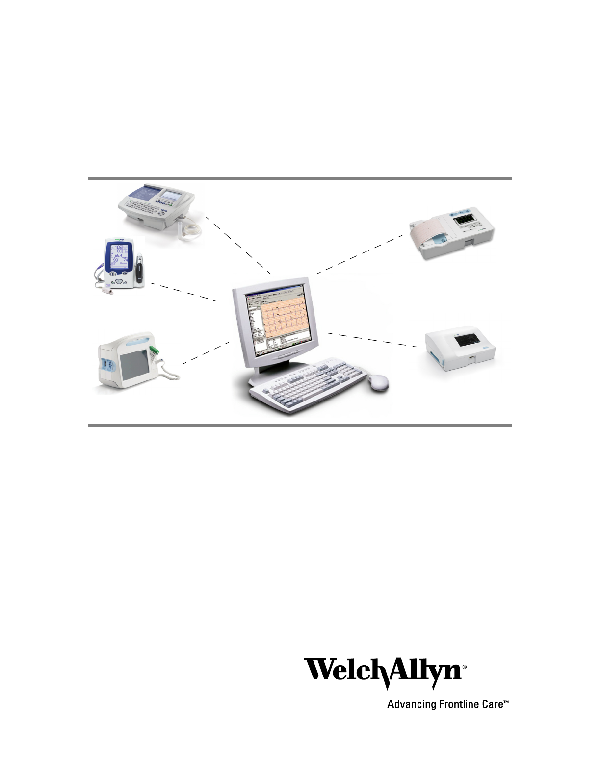
About Connex CSK software
The Welch Allyn Connex CSK software is a collection of software modules that enable
various Welch Allyn devices to communicate with systems such as CardioPerfect
Workstations.
Device WiFi Ethernet USB Serial Media
Wireless
USB
CP 50
CP 100
CP 150
CP 200
Spot LXi
VSM 6000
a. 802.11 b. Note: Welch Allyn supports two radio models for Spot LXi.
b. 802.11 a/b/g.
a, b
b
Removable
media
From a connected device, you can do the following:
• Send vitals data to data systems.
• Send ECG and/or spirometry tests to a CardioPerfect database.
• Recall patient information from a CardioPerfect database (CP 50, CP 150, CP 200 only).
• Retrieve patient order lists from an EMR/HIS using the Welch Allyn HL7 interface,
sold separately (CP 50, CP 150, CP 200 only).
Even without a connection, users of CP 50, CP 100, CP 150 and CP 200
electrocardiographs can transfer tests to a CardioPerfect database via removable media
(SD memory cards or USB storage devices).
Page 8
4 Overview Welch Allyn Connex CSK software
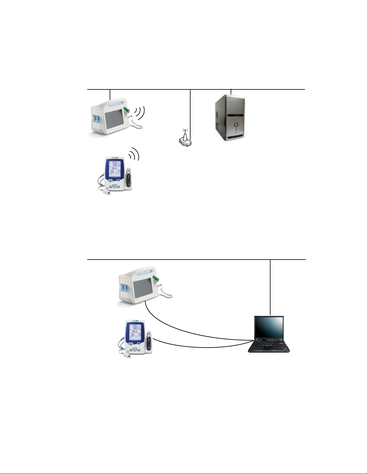
Spot LXi and VSM 6000 Series configuration examples
Client-server network configuration, wireless or Ethernet
Server
Installation menu option:
“Server”
Functional diagram:
“Software modules in a simple network configuration, wireless or Ethernet” on page 36
Client-server configuration
USB cable
Workstation (client)
Installation menu option:
“Client”
Functional diagram:
“Software modules in a USB configuration” on page 36
Page 9
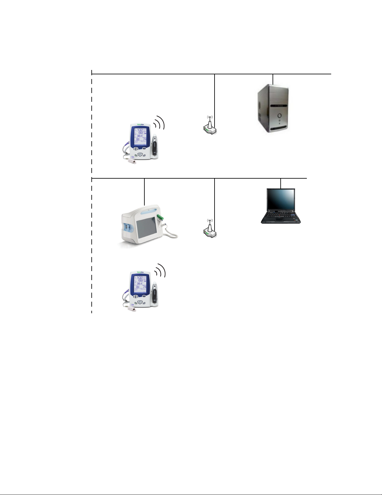
Installation guide Overview 5
Network configuration with multiple subnets
Subnet #1
Server
Installation menu option:
“Server”
Subnet #2
Workstation (client)
Installation menu option:
(to direct communications to the server)
“Advanced”
Page 10
6 Overview Welch Allyn Connex CSK software
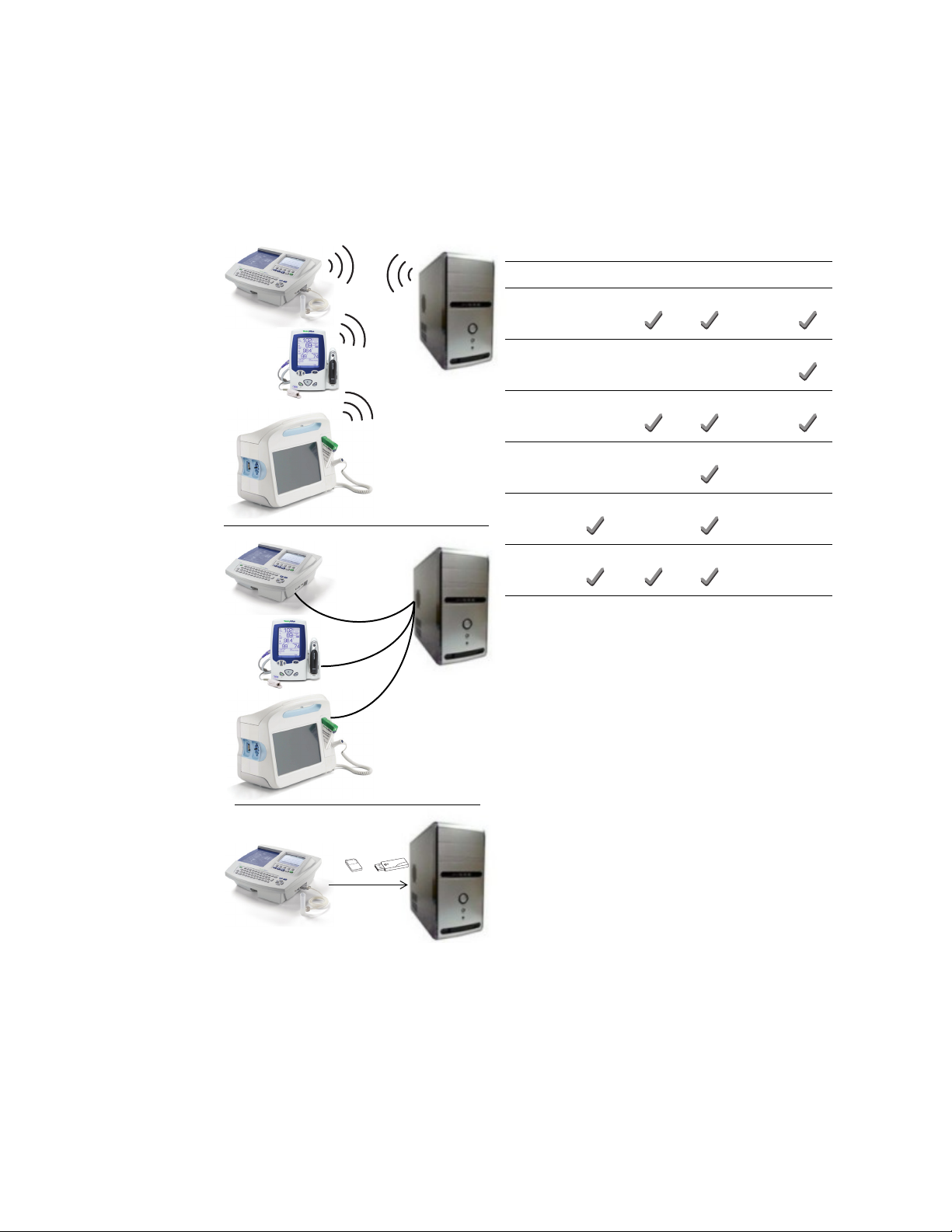
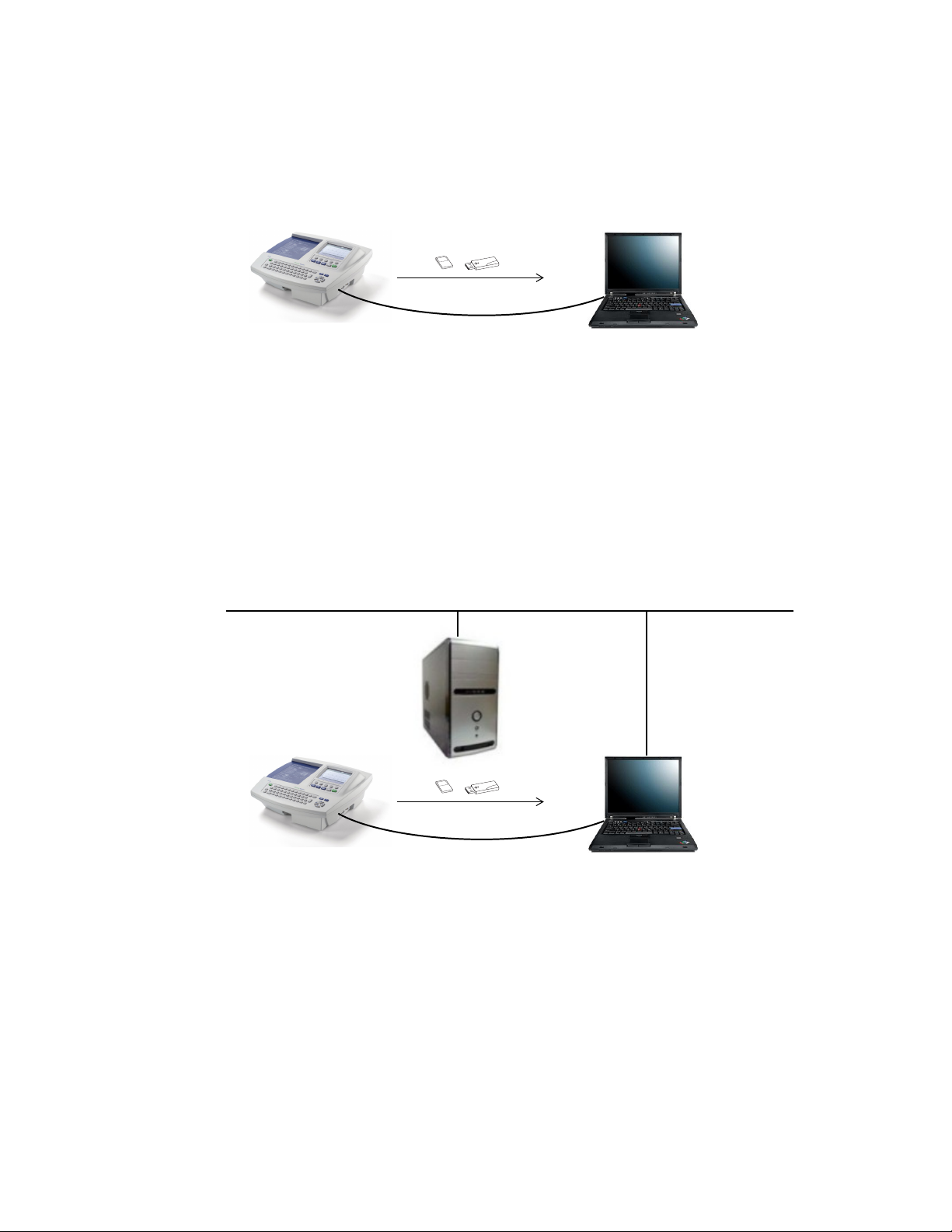
CP 50, CP 100, CP 150 and CP 200 configuration examples
Standalone configuration, removable media or USB
or
USB cable
CardioPerfect Workstation
Installation menu option: “Server”
Functional diagram:
“Software modules in a standalone CardioPerfect Workstation, removable media or USB” on page 34
Client-server configuration, removable media or USB
Server
Installation menu option:
“Server”
or
USB cable
Workstation (client)
Installation menu option: “Client”
Functional diagram:
“Software modules in a client-server configuration, removable media or USB” on page 35
Page 11
Installation guide Overview 7
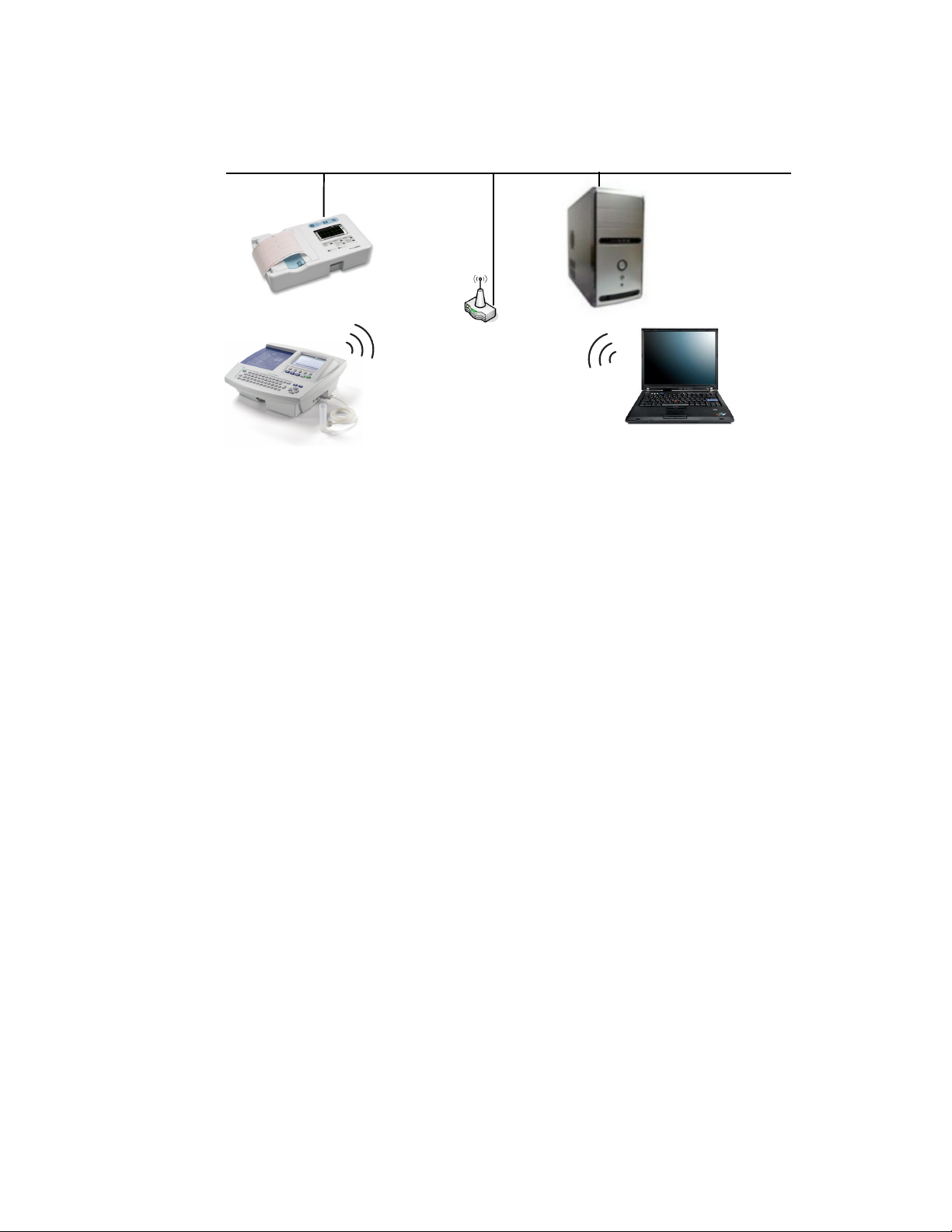
Network configuration, wireless or Ethernet
Server
Installation menu option:
“Server”
CardioPerfect Workstation (client)
No connectivity software installed
Functional diagram:
“Software modules in a client-server network configuration, wireless or Ethernet” on page 35
Page 12

8 Overview Welch Allyn Connex CSK software
Page 13
9
2
Installation
Spot LXi and VSM 6000 Series
Before you install the Welch Allyn Connex CSK software do the following:
• Verify that the connectivity settings in the device software are properly configured.
For details, see the device’s directions for use.
• When using a client/server configuration, please install the server software on the
database server before installing the clients.
• If using wireless communications, check the device’s settings. Verify that these
settings match the access point settings.
• Verify that you have administrator rights for the PC.
• Close all programs before starting the installation.
• If “Device driver signing” appears, select either “Yes” or “Continue.”
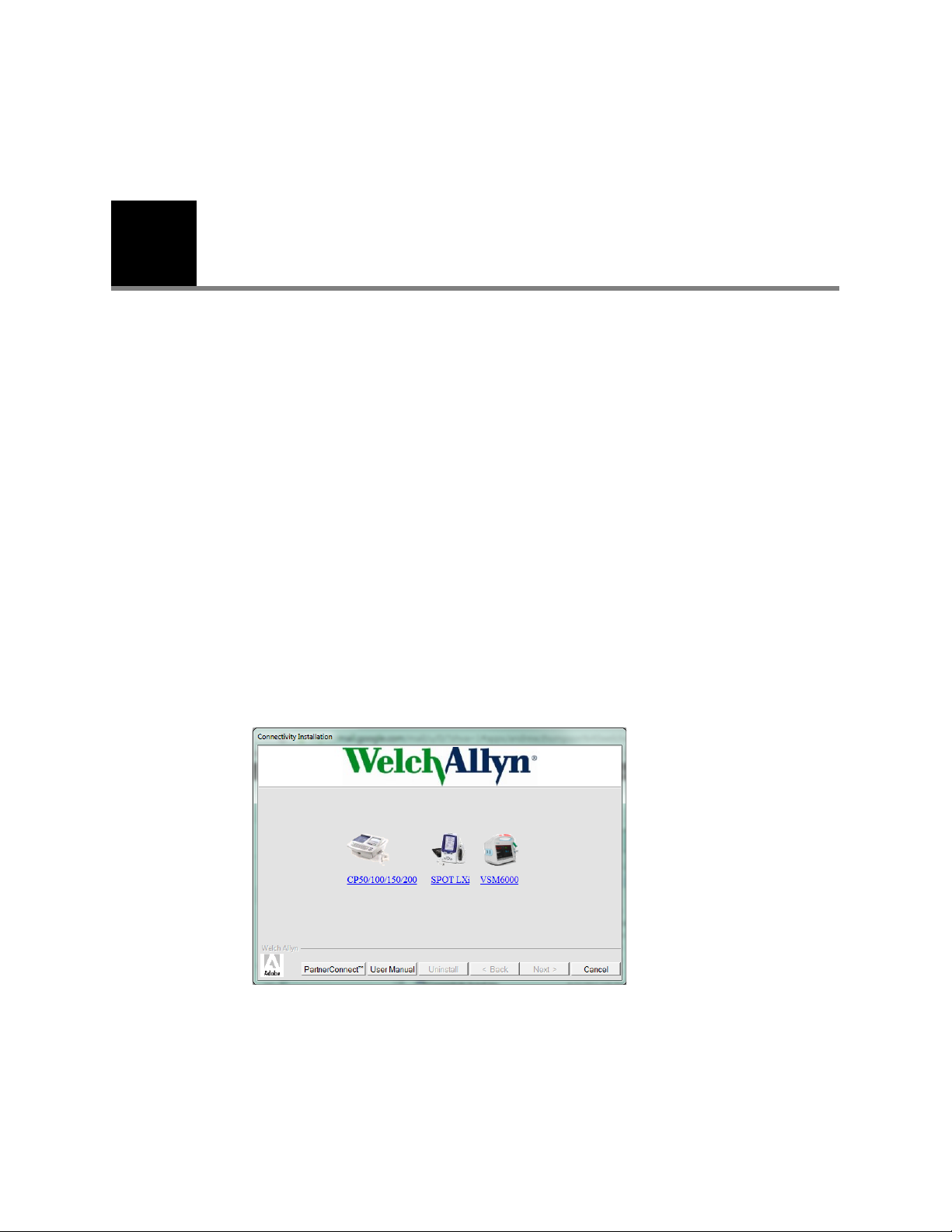
To install the Welch Allyn Connex CSK software
1. Insert the Connex CSK CD. This screen appears:
If this screen does not appear, open Connectivity Install on the CD.
Page 14
10 Installation Welch Allyn Connex CSK software
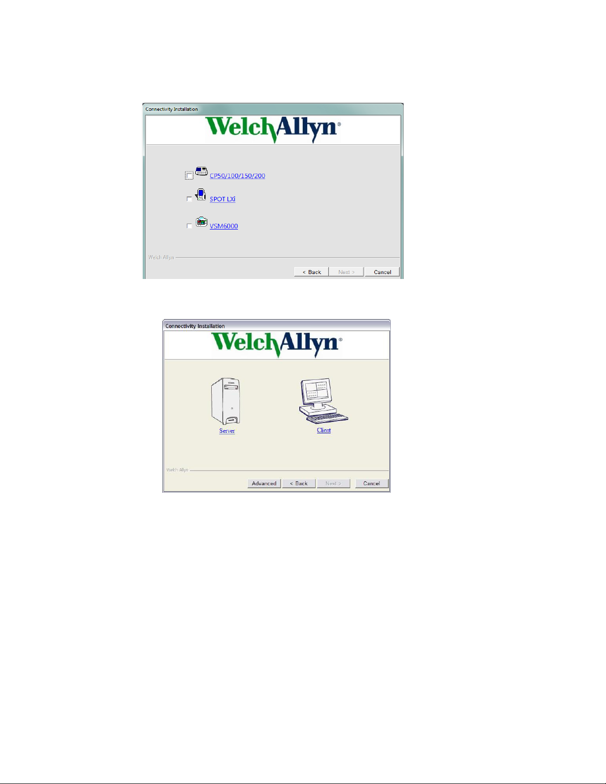
2. Select SPOT LXi or VSM6000. This screen appears:
3. Select SPOT LXi or VSM6000. This screen appears:
4. Choose either Server or Client based on your configuration.
For illustrations, see “Spot LXi and VSM 6000 Series configuration examples” on
page 4.
5. Follow the instructions on the screen.
Note
If using the removable media transfer option, make sure you transfer at least one
complete test record via USB or Network.
Page 15

Installation guide Installation 11
To uninstall the Welch Allyn Connex CSK software
1. Insert the Welch Allyn Connex CSK CD. This screen appears:
2. Select the Uninstall button.
3. Follow the prompts.
Page 16

12 Installation Welch Allyn Connex CSK software
CP 50, CP 100, CP 150, or CP 200
Before you install the Welch Allyn Connex CSK software do the following:
• If connecting to a CardioPerfect Workstation, do the following:
• Verify that the CardioPerfect Workstation software and database have both been
upgraded to version 1.6.0 or higher. If necessary, upgrade the software and
database now.
• When using a stand-alone CardioPerfect Workstation system, please install the
server software on the stand-alone CardioPerfect Workstation system
• When using a client/server configuration, please install the server software on the
CardioPerfect Workstation database server before installing the clients.
• Verify that the connectivity settings in the software are properly configured. For
details, see the electrocardiograph directions for use.
• If using a CP 200 electrocardiograph in a wireless configuration, do the following.
• Verify that the electrocardiograph software product version is 2.4.0 or later.
• Verify that the Wireless Settings item is available on the Connectivity Settings
menu. If not, a hardware upgrade is needed. Contact your Welch Allyn service
representative.
• Check the electrocardiograph’s network and wireless settings. Verify that these
settings match the access point settings.
For details, see the electrocardiograph directions for use.
• Verify that you have administrator rights for the CardioPerfect Workstation software
and for the PC.
• Close all programs before starting the installation.
• If “Device driver signing” appears, select either “Yes” or “Continue.”
Page 17

Installation guide Installation 13
To install the Welch Allyn Connex CSK software
1. Insert the Connex CSK CD. This screen appears:
If this screen does not appear, open Connectivity Install on the CD.
2. Select CP50/100/150/200. This screen appears:
Page 18

14 Installation Welch Allyn Connex CSK software
3. Select CP50/100/150/200. This screen appears:
4. Choose either Server or Client based on your configuration.
For illustrations, see “CP 50, CP 100, CP 150 and CP 200 configuration examples” on
page 6.
5. Follow the instructions on the screen.
Note
If using the removable media transfer option, make sure you transfer at least one
complete test record via USB or Network.
To uninstall the Welch Allyn Connex CSK software
1. Insert the Welch Allyn Connex CSK CD. This screen appears:
2. Select the Uninstall button.
3. Follow the prompts.
Page 19

15
3
Configuration
Configuring the CP 50, CP 150, and CP 200 patient-match criteria (resolving patients)
When a test is imported into the CardioPerfect database, the patient data submitted with
the test may or may not match patient data already stored in the database. The software
tries to match, or resolve, the incoming data against the stored data. Tests are entered
either for an existing patient or for a new patient, depending on the patient-match criteria.
MRN (medical record number) is a unique piece of text that identifies a patient. It is
usually a number, but it sometimes includes other information, such as social security
number or last name.
If the criteria are only partially satisfied, a suspect record may be created (.SUSPECT is
appended to the MRN).
The file named CPWS.Operations.CPWSImportTest provides a method of inserting a test
into the database. If the test already exists, it is replaced with the new test. Either
the patient indicated in the test is matched to a patient already in the database, or a new
patient is created. The criteria are controlled by the PatientMatchCriteria appSetting in
App.config (which compiles into CPWS.Service.exe.config).
To configure the patient-match criteria
1. Open this file: C:\Program Files\Welch Allyn\CPSAPI\CPWS.Service.exe.config.
NoteNote
2. Replace the key attribute with the desired PatientMatchCriteria value in this line:
On 64-bit systems, the file path is C:\Program Files (x86)\Welch
Allyn\CPSAPI\CPWS.Service.exe.config.
Windows Vista and Windows 7 users: Open this file as an administrator, as follows.
a. Click the Start button. Select All Programs > Accessories.
b. Right-click Notepad. Select Run as Administrator. Notepad opens.
c. Click File > Open. Open CPWS.Service.exe.config.
<add key="PatientMatchCriteria" value="MATCH_MRN"/>
Page 20

16 Configuration Welch Allyn Connex CSK software
PatientMatchCriteria Description
MATCH_MRN This is the default setting. The MRN must match exactly. If the MRN is empty, the
MATCH_MRN_DOB_
GENDER
MATCH_MRN_DOB_
GENDER_LASTNAME
MATCH_DOB_
LASTNAME_FIRSTNAME
record is marked suspect.
The MRN, date of birth and gender must match exactly. If this fails but the MRN
matches or is empty, the record is marked suspect.
The MRN, date of birth, gender and last name must match exactly (case-insensitive).
If this fails but the MRN matches or is empty, the record is marked suspect.
The first name and last name must match exactly, and the date of birth must be on the
same day.
• If there is no match, but the MRN conflicts with another entry, the record is
marked suspect.
• If there is no match and the MRN is blank, the MRN is set to a period, the
patient’s last name, a period, and a unique number.
This is the only setting that allows a blank MRN, which gets automatically generated.
3. Save the file.
4. Restart the CPSAPI service. (Go to Control Panel > Administrative Tools >
Services. Right-click CardioPerfect Services. Select Restart.)
Page 21

Installation guide Configuration 17
Configuring the CardioPerfect Workstation for non-Welch Allyn devices
CardioPerfect Workstation uses the SCP-ECG plug-in, which is a standard
communications protocol for computer-assisted electrocardiography (EC71 or EN1064).
This plug-in, which works with the CPSAPI software module, enables you to configure the
CardioPerfect Workstation software to import resting ECG tests from non-Welch Allyn
devices and to export ECG tests to non-Welch Allyn record management systems using a
format translator, for example Datamed (sold separately).
To configure CPSAPI plug-ins, you modify an XML configuration file, and then restart the
CardioPerfect Services service.
The plug-in file, named CPSAPI.config, is stored in the local folder with the CPSAPI
service executable. By default, this folder is C:\Program Files\Welch Allyn\CPSAPI. On 64bit operating systems, the path is C:\Program Files (x86)\Welch Allyn\CPSAPI.
For a description of the CPSAPI module, see “Configuring the CP 50, CP 150, and CP 200
patient-match criteria (resolving patients)” on page 15.
To configure the plug-in for automatic ECG exporting
This procedure configures the CardioPerfect program to export ECG tests from the
CardioPerfect database automatically when they are captured and saved in the specified
folder.
1. Find the SCP-ECG Collector entry in CPSAPI.config.
Example:
<ResultCollector name=”SCP-ECG Collector” enabled=”1” standalone=”1”
type=”CPWS.Plugins.ResultCollector.SCPECGCollector,CPWS.Plugins” values=”” destinationfolder=”specify export
folder here” />
2. Modify the enabled and destinationfolder attributes as desired.
Attribute Description Possible Values
enabled Specifies whether CPSAPI should load and execute the plug-in. 0 (Off), 1 (On)
destinationfolder Specifies the output folder where SCP-ECG files will be created.
Caution: The destination and source (export and import) folder
names must be unique. If these folder names are identical, the
system will not operate properly.
3. Restart the CPSAPI service.
a. Go to Control Panel > Administrative Tools > Services.
Any valid Windows path
b. Right-click CardioPerfect Services.
c. Select Restart.
Page 22

18 Configuration Welch Allyn Connex CSK software
To configure the plug-in for automatic ECG importing
This procedure configures the CardioPerfect program to import ECG tests into the
CardioPerfect database automatically when new SCP files appear in the specified folder.
1. Find the TestFileImporter entry in CPSAPI.config.
Example:
<TestFileImporter name=”SCP-ECG Test Importer” enabled=”1”
type=”CPWS.Plugins.TestFileImporter.SCPECGTestFileImporter,CPWS.Plugins” sourcefolder=”specify importfolder here”
/>
2. Modify the enabled and sourcefolder attributes as desired.
Attribute Description Possible Values
enabled Specifies whether CPSAPI should load and execute the plug-in. 0 (Off), 1 (On)
sourcefolder Specifies the import folder for incoming SCP-ECG files.
Caution: The destination and source (export and import) folder names
must be unique. If these folder names are identical, the system will
not operate properly.
3. Restart the CPSAPI service.
a. Go to Control Panel > Administrative Tools > Services.
b. Right-click CardioPerfect Services.
c. Select Restart.
Any valid Windows path
Page 23

Installation guide Configuration 19
Data Catcher configuration
The Data Catcher application acts as a gateway between devices and external information
hosts. The configuration interface is described in the following section.
NoteNote
This interface is for advanced users only. The software installation configures
Data Catcher for the configuration selected during the installation. Only use this
when an advanced, non-standard configuration is required.
Configuration interface
As part of the configuration interface, a system tray icon is included.
The following sections show and describe elements of the configuration interface.
Opening panel
1
2
1 Settings categories Lists the configuration sub-categories for Data Catcher. By clicking on an option, the
2 Status bar Describes the last action performed during configuration to provide feedback about
panel on the right will be populated with the related settings.
your actions.
Page 24

20 Configuration Welch Allyn Connex CSK software
General settings
1
2
3
4
5
6
7
8
1 Start button Selecting this starts the device server portion of Data Catcher.
2 Stop button Selecting this stops the device server portion of Data Catcher. All state information
3 Automatic
configuration
4 Local Data Cache
directory
5 Local Data Cache
file types
pertaining to currently pending information host messages will also be reset.
This option allows you to fully configure Data Catcher using an existing configuration file.
This will copy the specified file to the Data Catcher directory, rename the file to
“DataCatcherConfig.xml,”and force the application to restart to reload the new
configuration.
Note: This will disconnect any current devices in the same way the Stop button works.
This will also restart the Web interface portion of the application to employ any user
interface changes.
Data Catcher provides the option to save all device data sent through the system to a local
directory. This data is the unaltered data, directly from the device. This configuration
option specifies the directory where the cached device data files should be stored, relative
to the application directory.
This option allows you to specify what types of data files should be cached locally. You can
choose to save the pure binary data from the device, an XML form of the data, or both.
Each file is uniquely named using a combination of the device source ID, the current
system time, and a randomly generated number.
6 Local Failed Data
Cache directory
This option only applies to messages that have failed to respond to the device. If there is
an error that cannot complete its round trip, a copy of the original message will be stored
here.
Page 25

Installation guide Configuration 21
7 Local Failed Data
Cache file types
8 Save settings Selecting this commits any changes made to the configuration settings. This will update
This option allows you to specify what types of failed message data files should be cached
locally. You can choose to save the pure binary data from the device, an XML form of the
data, or both. Each file is named using a combination of the device source ID, the current
system time, and a randomly generated number.
the application settings on the fly, and save the changes to the “DataCatcherConfig.xml”
file.
Page 26

22 Configuration Welch Allyn Connex CSK software
Device network settings
1
2
3
4
1 Device
transmission
timeout
2 Definition
cache
3 Connection
types
4 Device
heartbeats
This value represents the maximum time, in seconds, that a device can be connected to Data
Catcher with no communication before the device is disconnected.
This value represents the local or path to the directory where cached definitions are stored.
Note: Cached definitions are only loaded when Data Catcher starts, so any additions or
updates to these files will not be recognized until the application restarts.
These checkboxes represent the supported connection types for the device server portion of
Data Catcher.
Note: The “Serial” option available applies to both normal serial connections, and USB
Serial Host Driver connections (for example CP 200 USB).
Note: Changes to this option will not be reflected by Data Catcher until the application is
restarted.
This value represents the interval (in seconds) at which heartbeat pings will be sent to
known client devices. This is a standard ICMP ping echo request, sent to a networking client.
When set to “0,” heartbeat pings are disabled.
When a client device connects, it will be marked as a known client and flagged as active.
Once the interval has elapsed, a ping request will be sent to each known client in parallel.
Once a client responds to the request with an echo response, the client will be flagged as
active. If any clients have not responded after one second, a retry request will be sent to
those clients. Up to four retries will be attempted, and any clients that have not responded
after the fourth attempt will be flagged as inactive.
Once the retries have completed, the list of active and inactive device clients will be
forwarded to the host system. Once the list is sent, all inactive clients are removed from the
device list.
Page 27

Installation guide Configuration 23
Information network settings
1
2
3
4
5
6
7
8
9
10
11
12
13
14
15
1 Data
transmission
timeout
2 Multiple
external host
management
3 Host authority This option identifies whether the currently selected external host should be used to
4 File output This option specifies whether the output should be written to file instead of forwarded to an
This value represents the maximum time, in seconds, that a connection will be maintained
with an external information host. If no response is received from an information host within
this time interval, for a specific message context from a device, Data Catcher will send a
NACK to the relative device and close the connection to the information host.
This option allows Data Catcher to act as a message branch, and forward device messages
to multiple external host systems. Each message received from a device will be duplicated
and sent to each host specified in this list. Each host has its own related configuration page
and information, and can specify separate IP addresses, payload options, and transform
sheets. The Add/Remove buttons are used to add new, blank host information pages, and
remove currently selected host information pages based on the displayed index.
Since a single device message can be branched to multiple host information systems, the
“Host Authority” option (XREF) allows you to specify how the responses from these hosts
should be used to determine the success state of the transmission.
determine the success state of a data transmission or not. This is primarily used when
multiple external hosts are configured for Data Catcher.
external host, and to what directory the output file should be written.
Page 28

24 Configuration Welch Allyn Connex CSK software
5 Automatic host
resolution
6 Host type When the “Automatic Host Resolution” option is enabled, this option becomes available. It
7 Host address This is the IPv4, dot-separated address, or DNS lookup name for the external information
8 Host port This is the application port value available on the external information host where Data
9 Reuse
connections
10 SSL option This option enables or disables the use of SSL (Secure Sockets Layer) encryption when
In certain system configurations, the IP address of the external host is either not known at
configuration time, or not static. In these cases, the IP address of the host cannot be
determined ahead of time, and must be resolved at the time that connections to the host are
attempted. This feature uses an integrated DCP client to find hosts automatically when
devices send messages to Data Catcher.
When this option is enabled, the “Host IP Address” and “Host Port” fields are disabled, as
this setting overrides those options. Also, the “Host Type” option becomes enabled, and lets
you choose which hosts they would like to find automatically when messages are routed
through the system.
lets you choose which external host types to look for when finding automatic hosts.
There are two fields associated with this option – a manually edited numeric field, and a
dropdown box of predefined selections. If no host types are known that match the index, a
value of “Unknown” is displayed.
host where device data will be forwarded.
Note: The connection established with the information host is a standard TCP connection.
Catcher will connect.
This option enables of disables the connection reuse algorithm. When this option is
enabled, messages from all devices to a single information host will be routed through a
single, established connection, synchronously. If no connection is available, a new
connection is established.
When this option is disabled, a new asynchronous TCP connection is established every time
a new data message is forwarded to an information host.
communicating with an information host.
When this option is enabled, an SSL session is established whenever a connection is made
to the configured information host. All messages that are transmitted to the information
host are then encrypted with the SSL algorithms.
When this option is disabled, a standard, un-encrypted TCP connection is used.
11 Payload type This option determines if Data Catcher will forward WACP-formatted XML data, or binary
12 XSLT Clear These buttons will clear the selected XSLT file for the associated field. This will not delete
13 Outbound XSLT The outbound XSLT field is used to specify the location of an .xsl file that will be used to
data to external information hosts.
Note: If an outbound XSLT file is specified, the WACP-formatted XML is translated using
that file and then sent. If no file is specified, the XML is sent directly without translation.
the XSLT files from the related directory. It will only remove the assignment of that XSLT file
for message processing in Data Catcher.
translate data from a device to the format accepted by the information host. You can browse
for an .xsl file, which will be copied and saved to Data Catcher’s own local storage directory.
All data collected from devices is translated from the native binary format from the device to
the XML format. At that point, the XML data is then transformed using the provided
outbound XSLT sheet, and forwarded to the specified external information host. This allows
an administrator to provide a specialized transformation sheet designed for the information
host that will format the data to fit the needs of the information host’s interface.
Page 29

Installation guide Configuration 25
14 Host response
XSLT
15 Device
response XSLT
The Host Response XSLT field is used to specify the location of an .xsl file that will be used
to verify responses from an external information host. Whenever XML data, or translated
data, is sent to an information host, the data message is saved as part of the message
context. If a Host Response XSLT file is specified, it is used to translate that original
outbound message into an expected response. This expected response is then compared
against the actual response from an information host.
If no Host Response XSLT is specified, then any response from an information host,
regardless of content, will result in an ACK back to the device.
If an appropriate, matching host response is received from an external information host, and
a Device Response XSLT is present, then Data Catcher generates a specific response for the
device using this XSLT. This response can include elements saved from the Host Response
comparison (using set-variable and get-variable), it can use custom generated binary data
(using binary-stream), and it can conditionally decide whether an ACK, NACK, or custom
message id should be sent to the original device. This allows the XSLT developer a large
amount of flexibility in controlling the response to the device, above and beyond the generic
ACK/NACK responses.
Page 30

26 Configuration Welch Allyn Connex CSK software
User interface settings
1
2
1 Web port The port value that will host the Web interface for Data Catcher.
2 Interface enabled This option enables or disables the Web interface. If this is enabled, the application can be
Note: Any changes to the web port value will force the web-interface portion of Data
Catcher to restart. This means you must close the interface and re-open it to continue
configuration.
configured as normal through the configuration interface. If this is disabled, you will not be
able to access the configuration interface.
Note: The only way the interface can be re-enabled after being disabled is to stop the
application, manually edit the “DataCatcherConfig.xml” file to enable the interface, and
restart the application.
Page 31

Installation guide Configuration 27
Data logs
To provide assistance in monitoring messages that are processed by Data Catcher,
specifically ones that fail to complete their round-trip delivery, a Data Log option is
available on the left side of the configuration interface. This option will open a new
window and display a list of data messages that have been received from devices by Data
Catcher, but for some reason have not completed their process successfully.
This log displays information contained within the data messages themselves (for
example Patient ID, Date/Time, Serial Number of the device, etc) to help determine if the
error was a result of improper device data, or if it was from an internal processing error.
For the Data Log option to work, Data Catcher must have the Failed Data Cache option
enabled (see “Local Failed Data Cache directory” on page 20), and must have XML
formatted data enabled for this option (see “Local Failed Data Cache file types” on
page 21). If either of these options are missing or not enabled, the Data Logs will not be
available.
Debug logs
The Data Catcher application generates a running log with debug information as it
executes. It maintains two logs (“DebugLog1.txt” and “DebugLog2.txt”) that store this
information, and writes to the two files in a circular manner. When the application starts, it
opens “DebugLog1.txt” to write first, and continues to write information to this file until it
reaches the specified capacity (10 Megabytes). Once this limit has been reached, the
application opens “DebugLog2.txt” and continues writing until once again the capacity
limit has been reached. Then, the application reopens “DebugLog1.txt”, clears all data
from the file, and continues writing.
Page 32

28 Configuration Welch Allyn Connex CSK software
Adding CVSM to a Connex CSK installation
The Connex VSM is only supported on CSK installations of version 4.0 and higher, so you
must verify that your Connex CSK installation is valid before proceeding.
To verify if your Connex CSK installation is valid
1. Navigate to the Welch Allyn installation directory (by default C:\Program Files\Welch
Allyn\”).
2. Open versions.txt and search for the term “Full Connectivity Package.” Verify that the
version listed here is greater than or equal to 4.0 (4.0.0.x).
3. If the version is less than 4.0, follow the instructions listed in the readme.txt file on
the CD for “Updating from Connex CSK Version 3.0 to Version 4.0.”
NoteNote
Once you have either confirmed you are using CSK 4.0, or have upgraded to it, you may
need to add custom XSLT configurations to handle data from your CVSM device.
To add custom XSLT configurations to handle data from a CVSM device
1. Open the Data Catcher configuration page through the system tray icon. Click on
2. To add a new data path for the device, click Add next to Host Index. This will add a
3. If you wish to communicate with a information host that will receive device data,
4. If you wish to write device data to a file on the local PC, select the Write Output to
5. Check the Use XML payload option under the Payload settings field.
NoteNote
During the installation process of CSK 4.0, make sure that the existing devices are
selected along with the CVSM.
Information Network on the left.
new, empty host configuration and the Host Index field will update to represent the
index of the new entry.
enter the Host address and port information in the appropriate fields. Check the
Reuse Connection and SSL options if needed.
File option. Fill in an appropriate directory where you would like the output data to be
stored.
In some very specific cases, the “Use binary payload” option can be used if no
XML transformation is desired. However, this option requires an intimate
knowledge of the WACP binary protocol formats, and should only be selected if
you have worked with a Welch Allyn engineer to develop your interface.
6. Select any custom XSLT sheets that will be used to transform device data to the
format compatible with the host system’s interface.
NoteNote
The XSLTs used for custom interfaces are ones you develop. Welch Allyn can
provide support and consultation in developing these XSLTs, but maintenance and
verification of them is your facility’s responsibility.
Page 33

Installation guide Configuration 29
Connecting Connex CSK to multiple device models
If you wish to connect multiple devices models to CSK, you will need to edit your XSLT
sheets to handle each device model. If you have an LXi device and CVSM device, there
are two options. Pick the option that suits your needs.
1. If there are two separate host systems installed, one for handling data from LXi
devices and one for handling data from CVSM devices, then you should follow Step 2
on page 28 to configure two Host Index entries. There should be one entry with
custom XSLT sheets specifically for handling LXi data, and a second entry with
different XSLT sheets specifically for handling CVSM data. Inside these XSLT sheets,
the script should filter data based on GUIDs, so that only data from the associated
device model is handled by the respective XSLT.
2. If there is a single host system installed that handles all data from both device
models, then you should follow Step 2 on page 28 to configure one Host Index entry.
This entry should have a XSLT sheet for handling both LXi data and CVSM data. Inside
the XSLT sheet there should be sections for handling each device model’s data based
on GUID filtering. One section would handle all data from LXi devices, while the other
section would handle all data from CVSM devices.
Replacing a Spot LXi with a CVSM
If you are replacing one device model with another, instead of using both simultaneously,
then the steps to configure Data Catcher are very similar to what has already been
described.
To replace a Spot LXi with a CVSM
1. Open the Data Catcher configuration page through the system tray icon. Click
Information Network on the left.
2. To remove an existing data path for a device, select the appropriate Host Index entry
with the drop-down box, and click Remove located next to the Host Index field. Click
Save Settings to confirm the removal.
3. See “Adding CVSM to a Connex CSK installation” on page 28 to add a new Host Index
entry for the CVSM device.
Adding a CVSM to a system already using a Spot LXi
No global settings should need to change when adding a CVSM device to the system. The
only change would be to Step 2 on page 28, where additional Host Index entries may
need to be added on the Information Network page.
Page 34

30 Configuration Welch Allyn Connex CSK software
File Importer configuration
File Importer is a software program that allows you to transfer patient vitals from an
external media drive into CardioPerfect.
Options tab
The options tab allows you to change your configuration settings.
1
2
3
4
5
6
1 Outgoing file folder This is the folder containing a copy of the files sent to the Information Host.
2 Failed file folder Folder containing a copy of the files that failed to send to the Information Host.
3 External media
drive
4 External media
folder
5 File types to import File types (extensions) that the software will look for in the External Media Folder on the
6 Information host
address
Disk drive representing the removable media where the tests are stored.
Folder on the removable media containing the tests to be imported.
External Media Drive to import.
Web address of the web service where the files are to be sent. The only part that could
be configured is the “localhost:9247.”
Page 35

Installation guide Configuration 31
Logs tab
The Logs tab allows you to read logged messages to either confirm a test was imported
correctly or determine why an import failed.
Import failures tab
This tab shows a list of files (tests) that were not able to be imported.
1 Delete Allows you to remove this file from the system.
2 Retry Allow you to correct the problem and retry to send the file.
1
2
Page 36

32 Configuration Welch Allyn Connex CSK software
Page 37

33
4
Troubleshooting
About the connectivity software modules
The Connex CSK software comprises a set of modules that are installed separately as
needed. The connectivity modules are listed here:
Module Full name Description Installation location
CPSAPI CardioPerfect
Server
Application
Programming
Interface
DC Data Catcher This module receives data from the device(s). One DC per CPSAPI installation
DCP Device
Communication
Protocol
FI File Importer This module receives tests from removable media
This is the database connectivity module. It plays a
central role, directing communications between
various software modules and the server software.
This module listens for device(s) that are
connected wirelessly, and it tells them which IP
address to communicate with.
(SD memory cards or USB storage devices).
One CPSAPI per site
and per Workstation that supports
wired-USB
One DCP per subnet
One FI per Workstation receiving
tests via removable media
Firewall settings
If you are using a firewall between any PCs in your configuration, the following ports or
application files are required to gain access through the firewall. Software installation
automatically opens these ports.
Software module Port Type Application file
CPSAPI 9247 TCP CPWS.Service.exe
DCP 44435 UDP DCPd.exe
DCP 7711 UDP DCPd.exe
DC 281 TCP DataCatcher.exe
CP 200 ICMP Allow incoming echo requests Ping test
Page 38

34 Troubleshooting Welch Allyn Connex CSK software
Functional diagrams
Software modules in a standalone CardioPerfect Workstation, removable media or USB
FI
or
CardioPerfect
database
USB cable
DC
CardioPerfect
application
CardioPerfect Workstation (standalone)
Related illustration:
“Standalone configuration, removable media or USB” on page 6
CPSAPI
Software modules in a network configuration, wireless or Ethernet
DCP
DC
CPSAPI
CardioPerfect
database
CardioPerfect
application
CardioPerfect Workstation (standalone)
Page 39

Installation guide Troubleshooting 35
Software modules in a client-server configuration, removable media or USB
FI
or
USB cable
Related illustration:
“Client-server configuration, removable media or USB” on page 6
DC
CardioPerfect
application
CPSAPI
CardioPerfect database serverCardioPerfect Workstation (client)
CardioPerfect
database
Software modules in a client-server network configuration, wireless or Ethernet
DCP
CardioPerfect
database
DC
CardioPerfect database server
CardioPerfect
application
CardioPerfect Workstation (client)
Related illustration:
“Client-server network configuration, wireless or Ethernet” on page 4
CPSAPI
Page 40

36 Troubleshooting Welch Allyn Connex CSK software
Software modules in a simple network configuration, wireless or Ethernet
DCP
Related illustration:
“Client-server network configuration, wireless or Ethernet” on page 4
Software modules in a USB configuration
USB cable
DC
DC
XML
XML
Server
(Optional)
ServerWorkstation
Related illustration:
“Client-server configuration” on page 4
Page 41

Installation guide Troubleshooting 37
Reassigning a server IP address
Who needs this procedure?
Users with a client-server configuration wired to the client PC(s) or communicating via
removable media.
When do you need this procedure?
Anytime your server IP address changes.
What does this procedure accomplish?
It enables the software to pick up a newly assigned server IP address.
How do you do this procedure?
Restart the computer’s DCP daemon Windows service.
a. Go to Control Panel > Administrative Tools > Services.
b. Right-click DCP Daemon.
c. Select Restart.
No action is required at the client PC(s).
Page 42

38 Troubleshooting Welch Allyn Connex CSK software
Troubleshooting chart
Conditions Causes Actions
1. View Available
Networks screen
does not return any
available networks
(CP 200).
2. Ping operation failed. Wrong IP address entered. Check other computer's IP address.
Outside range of all wireless
networks.
There are no wireless networks
available.
Device radio is not connected. Connect CP 200 radio. Verify that the CP 200 radio lights are blinking or
Device configuration. Check the CP 200 network settings and connectivity mode. Verify that these
The device cannot connect to the
network.
The device cannot properly connect
to the network.
Firewall settings. The firewall needs to be set to “Allow echo requests.” (See “Firewall
Device configuration. Check the device network settings and connectivity mode. Verify that these
Move within the wireless network.
Verify that the wireless network router(s) are powered up and properly
configured.
solid to indicate action.
settings match the access point settings.
Check wireless settings and ensure that they match the access point
settings.
Wireless:
Check wireless settings and ensure that they match the access point
settings.
Ethernet:
1. Connect the network cable.
2. Wait a few seconds.
3. Navigate to the network setting screen and verify that the device has a
valid IP address.
settings” on page 33.)
settings match the access point settings.
3. Server test operation
failed.
The device cannot properly connect
to the network.
Connectivity software not installed
on a computer on the network.
DCP module is not running. Check the services to verify that the DCP daemon service is running.
Firewall settings. Check firewall to ensure that exceptions are set. (See “Firewall settings” on
Device configuration Check the device network settings and connectivity mode. Verify that these
The server IP address has changed. See “Reassigning a server IP address” on page 37.
Multiple subnets. Check your network router settings; enable multicasting across subnets.
Unknown 1. Determine the IP address of the PC running Data Catcher.
Wireless:
Check wireless settings and ensure that they match the access point
settings.
Ethernet:
1. Connect the network cable.
2. Wait a few seconds.
3. Navigate to the network setting screen and verify that the device has a
valid IP address.
Install Connex CSK on the same computer as CardioPerfect database.
page 33.)
settings match the access point settings.
2. Perform a ping test to this IP address. If the ping test passes, the
network connection is OK.
3. Perform a server test, if the server test fails then either DCP or Data
Catcher is not running or in error state.
4. Restart the DCP or Data Catcher, and try the server test again.
Page 43

Installation guide Troubleshooting 39
Conditions (continued) Causes (continued) Actions (continued)
4. Test send (or
patient search) failed
— wireless or
ethernet.
No patient order found or patient
search contained no results
The device cannot properly connect
to the network.
Outside range of all wireless
networks.
There are no wireless networks
available.
Device radio is not connected (CP
200 only).
Connectivity software not installed
on a computer on the network.
DCP module is not running. Check the services to verify that the DCP daemon service is running.
Data Catcher is not running. Check the services to verify that the Data Catcher service is running.
Data Catcher is not receiving files. Verify that the C:\Program Files\Welch Allyn\DataCatcher\SavedCopies
Server does not contain any patients that match the search criteria.
Wireless:
Check wireless settings and ensure that they match the access point
settings.
Ethernet:
1. Connect the network cable.
2. Wait a few seconds.
3. Navigate to the network setting screen and verify that the device has a
valid IP address.
Move within the wireless network.
Verify that the wireless network router is powered up and properly
configured.
Connect CP 200 radio. Verify that the radio lights are blinking or solid to
indicate action.
Install Connex CSK on the same computer as CardioPerfect database.
folder has new files with a date/time stamp about when you sent it and
that the folder updates as you send more tests.
• If yes, Data Catcher is getting files. Check CPSAPI.
• If no, Data Catcher is not working. Reinstall server software or
check firewall.
CardioPerfect services (CPSAPI) is
not running.
CP 200 configuration. Ensure that Connectivity Mode is set to Wireless.
The server IP address has changed. See “Reassigning a server IP address” on page 37.
Firewall settings. Check firewall to ensure that exceptions are set. (See “Firewall settings” on
Unknown 1. Determine the IP address of the PC running Data Catcher.
Data Catcher is not receiving files Check to make sure the proper device connection type is enabled:
Verify that the CardioPerfect Services service is running.
page 33.)
2. Perform a ping test to this IP address. If the ping test passes, the
network connection is OK.
3. Perform a server test, if the server test fails then either DCP or Data
Catcher is not running or in error state.
4. Restart the DCP or Data Catcher, and try the server test again.
1. Open the Data Catcher configuration page through the system tray
icon. Click on Device Network on the left.
2. Check Supported Connection Types to make sure the proper
channels are enabled.
Note: WiFi connections from devices require TCP to be enabled. USB
connections from the CP200 require Serial to be enabled.
3. Click Save Settings to save your changes
4. If using WiFi wireless connectivity, verify that the device wireless
settings (SSID, etc.) matches the network settings.
Page 44

40 Troubleshooting Welch Allyn Connex CSK software
Conditions (continued) Causes (continued) Actions (continued)
5. Test send
(or search) failed —
USB cable.
Cables not connected. Make sure USB cable is connected on both ends (device and PC).
Connectivity software not installed. Install Server Connectivity option on the computer containing the database,
CP 200 configuration. Ensure that Configuration Mode is set to Wired.
Data Catcher is not running. Check the services to verify that the Data Catcher service is running.
Data Catcher is not receiving files. Verify that the C:\Program Files\Welch Allyn\SavedCopies folder has new
CardioPerfect services (CPSAPI) is
not running.
The server IP address has changed. See “Reassigning a server IP address” on page 37.
Firewall settings. Check firewall to ensure that exceptions are set. (See “Firewall settings” on
Incorrect cable. CP 50 and CP 150: Verify that you are using an A-to-mini-B USB cable.
Data Catcher is not receiving files Check to make sure the proper device connection type is enabled:
and install the Client option on the USB computer. Ensure that the device is
connected and the PC driver is loaded.
files.
• If yes, Data Catcher is getting files. Check CPSAPI.
• If no, Data Catcher is not working. Reinstall Client software or
check firewall.
Verify that the CardioPerfect Services service is running on the computer
containing the database.
page 33.)
CP 200: Verify that you are using an A-to-A USB cable.
1. Open the Data Catcher configuration page through the system tray
icon. Click on Device Network on the left.
2. Check Supported Connection Types to make sure the proper
channels are enabled.
Note: WiFi connections from devices require TCP to be enabled. USB
connections from the CP200 require Serial to be enabled.
3. Click Save Settings to save your changes
4. If using WiFi wireless connectivity, verify that the device wireless
settings (SSID, etc.) matches the network settings.
6. Test send failed removable media
Connectivity software not installed. Install Server Connectivity option on the server containing the database,
Client software is not installed on
the computer intended to be the
transfer station.
Tests not on removable media. Refer to the device’s directions for use for details on sending tests to
File Importer is configured for
“Auto,” but it ignores drives A and B.
File Importer reports a failure. Verify that client and server have connectivity and that CPSAPI is running,
File Importer has been manually
disabled.
The server IP address has changed. See “Reassigning a server IP address” on page 37.
and install the Client option on the USB computer. Ensure that the device is
connected and the PC driver is loaded.
Install the Client software option on the computer intended to be the
transfer station.
memory card.
Set File Importer to select the proper external media drive.
then retry: Right-click the File Importer tray icon, select “Import Failures,”
select the failed file(s), and press Retry.
Right-click the File Importer tray icon, and uncheck the “Disable” menu.
Page 45

Installation guide Troubleshooting 41
Conditions (continued) Causes (continued) Actions (continued)
7. Data Catcher
configuration page is
inaccessible
8. CPWS patient
number has
.SUSPECT appended
to the patient
number
9. Datamed interface is
not working
The configuration web-interface has
been disabled
There is another application already
running on the PC which is using the
port the web-interface would
normally use.
The CP 200 patient-match criteria is
only partially satisfied.
The plug-in is not enabled. See “Configuring the CardioPerfect Workstation for non-Welch Allyn
1. Open DataCatcherConfig.xml (located in the Data Catcher
installation directory) with a text editor.
2. Search for “InterfaceEnabled.” On the line following this term, find the
section that reads “<![CDATA[0]]>”.
3. Edit the file and replace the 0 with a 1, so the entry reads:
“<![CDATA[1]]>”.
Note: If the entry already reads “<![CDATA[1]]>”, then the web-interface is
enabled and something else is causing the access issue.
1. Open DataCatcherConfig.xml (located in the Data Catcher
installation directory) with a text editor.
2. Search for “ListenPort.” On the line following this term, find the section
that reads “<![CDATA[8000]]>.” The 8000 may be another numerical value,
if the web-interface port was changed in the past.
3. Edit the file to replace the 8000 with a new port value, one that you
know no other application is currently using.
See “Configuring the CP 50, CP 150, and CP 200 patient-match criteria
(resolving patients)” on page 15.
devices” on page 17.
Page 46

42 Troubleshooting Welch Allyn Connex CSK software
 Loading...