

Page 1
Welch Allyn Connex
®
CS
Central Station & Server
Admin Guide
Page 2

ii Welch Allyn
© 2014 Welch Allyn. All rights are reserved. To support the intended use of the product described in this publication,
the purchaser of the product is permitted to copy this publication, for internal distribution only, from the media
provided by Welch Allyn. No other use, reproduction, or distribution of this publication, or any part of it, is permitted
without written permission from Welch Allyn.
Welch Allyn assumes no responsibility for any injury to anyone, or for any illegal or improper use of the product, that
may result from failure to use this product in accordance with the instructions, cautions, warnings, or statement of
intended use published in this manual.
Welch Allyn and Connex are registered trademarks of Welch Allyn.
SQL Server, Visual Studio, Windows and Windows Server are all registered trademarks of Microsoft.
For patent information, please visit www.welchallyn.com/patents
Software in this product is Copyright 2014 Welch Allyn or its vendors. All rights are reserved. The software is protected
by United States of America copyright laws and international treaty provisions applicable worldwide. Under such laws,
the licensee is entitled to use the copy of the software incorporated with this instrument as intended in the operation
of the product in which it is embedded. The software may not be copied, decompiled, reverse-engineered,
disassembled, or otherwise reduced to human-perceivable form. This is not a sale of the software or any copy of the
software; all right, title, and ownership of the software remain with Welch Allyn or its vendors.
For information about any Welch Allyn product, contact Welch Allyn Technical Support (www.welchallyn.com/support
visit (www.welchallyn.com/about/company/locations.htm).
.
),
This device complies with Part 15 of the FCC rules and with the rules of the Canadian ICES-003. Operation is subject
to the following two conditions: (1) This device may not cause harmful interference and (2) this device must accept
any interference received, including interference that may cause undesired operation.
Caution! Changes or modifications not expressly approved by Welch Allyn could void the purchaser’s authority to
operate the equipment.
DIR 80018210 Ver. F
Welch Allyn, Inc.
4341 State Street Road
Skaneateles Fall, NY 13153-0220 USA
www.welchallyn.com
This manual applies to 901066 Monitoring Station
Regulatory Affairs Representative
Welch Allyn Limited
Navan Business Park
Dublin Road
Navan County Meath
Republic of Ireland
Page 3

Connex CS Admin Guide iii
Introduction. . . . . . . . . . . . . . . . . . . . . . . . . . . . . . . . . . . . . . . . . . . . . . . . . . . . . 1
About this manual. . . . . . . . . . . . . . . . . . . . . . . . . . . . . . . . . . . . . . . . . . . . . . . . . . . . . . . 1
Scope . . . . . . . . . . . . . . . . . . . . . . . . . . . . . . . . . . . . . . . . . . . . . . . . . . . . . . . . . . . . . . . . 1
Related Documents . . . . . . . . . . . . . . . . . . . . . . . . . . . . . . . . . . . . . . . . . . . . . . . . . . . . . 2
Symbols used in this manual . . . . . . . . . . . . . . . . . . . . . . . . . . . . . . . . . . . . . . . . . . . . . . 2
Definitions . . . . . . . . . . . . . . . . . . . . . . . . . . . . . . . . . . . . . . . . . . . . . . . . . . . . . . . . . . . . 2
Technical support services . . . . . . . . . . . . . . . . . . . . . . . . . . . . . . . . . . . . . . . . . . . . . . . . 3
Partners in Care service agreements . . . . . . . . . . . . . . . . . . . . . . . . . . . . . . . . . . . . . . . . 4
Connex components general maintenance . . . . . . . . . . . . . . . . . . . . . . . . . . . . . . . . . . . 4
Safety warnings and cautions . . . . . . . . . . . . . . . . . . . . . . . . . . . . . . . . . . . . . . . 7
Safety . . . . . . . . . . . . . . . . . . . . . . . . . . . . . . . . . . . . . . . . . . . . . . . . . . . . . . . . . . . . . . . . 7
General safety considerations . . . . . . . . . . . . . . . . . . . . . . . . . . . . . . . . . . . . . . . . . . . . . 9
Overview and System Hardware . . . . . . . . . . . . . . . . . . . . . . . . . . . . . . . . . . . 11
Overview . . . . . . . . . . . . . . . . . . . . . . . . . . . . . . . . . . . . . . . . . . . . . . . . . . . . . . . . . . . . 11
Central Station Computer Controls and Connectors . . . . . . . . . . . . . . . . . . . . . . . . . . . 13
Hardware Connex Server Computer Controls and Connectors . . . . . . . . . . . . . . . . . . . 15
Central Station Startup . . . . . . . . . . . . . . . . . . . . . . . . . . . . . . . . . . . . . . . . . . . 17
Different startup . . . . . . . . . . . . . . . . . . . . . . . . . . . . . . . . . . . . . . . . . . . . . . . . . . . . . . . 17
Power on the system . . . . . . . . . . . . . . . . . . . . . . . . . . . . . . . . . . . . . . . . . . . . . . . . . . . 18
Standard central station startup . . . . . . . . . . . . . . . . . . . . . . . . . . . . . . . . . . . . . . . . . . . 19
Warm Spare station startup . . . . . . . . . . . . . . . . . . . . . . . . . . . . . . . . . . . . . . . . . . . . . . 19
Connex Server Startup . . . . . . . . . . . . . . . . . . . . . . . . . . . . . . . . . . . . . . . . . . . 21
Server bootup screens . . . . . . . . . . . . . . . . . . . . . . . . . . . . . . . . . . . . . . . . . . . . . . . . . . 21
Confirm Connex Server operational state. . . . . . . . . . . . . . . . . . . . . . . . . . . . . . . . . . . . 23
Confirm communication with central stations . . . . . . . . . . . . . . . . . . . . . . . . . . . . . . . . 25
Confirm communication with EMR . . . . . . . . . . . . . . . . . . . . . . . . . . . . . . . . . . . . . . . . 25
Apply Customer Provided MSSQL Standard Licence Key . . . . . . . . . . . . . . . . . . . . . . . 28
Network, Printer, Time & Date config. . . . . . . . . . . . . . . . . . . . . . . . . . . . . . . . 29
Connex CS Shell versus Windows Shell. . . . . . . . . . . . . . . . . . . . . . . . . . . . . . . . . . . . . 29
Network Changes . . . . . . . . . . . . . . . . . . . . . . . . . . . . . . . . . . . . . . . . . . . . . . . . . . . . . . 30
Add a Customer Supplied Printer . . . . . . . . . . . . . . . . . . . . . . . . . . . . . . . . . . . . . . . . . . 31
Change Date, Time, and Time zone . . . . . . . . . . . . . . . . . . . . . . . . . . . . . . . . . . . . . . . . 32
Backup & Restore . . . . . . . . . . . . . . . . . . . . . . . . . . . . . . . . . . . . . . . . . . . . . . . 33
Backup users and configuration . . . . . . . . . . . . . . . . . . . . . . . . . . . . . . . . . . . . . . . . . . . 33
Nightly System Backup. . . . . . . . . . . . . . . . . . . . . . . . . . . . . . . . . . . . . . . . . . . . . . . . . . 35
Backup Corepoint configuration - create a NIX file . . . . . . . . . . . . . . . . . . . . . . . . . . . . . 36
Restore Patients and Users . . . . . . . . . . . . . . . . . . . . . . . . . . . . . . . . . . . . . . . . . . . . . . 40
Restore Settings . . . . . . . . . . . . . . . . . . . . . . . . . . . . . . . . . . . . . . . . . . . . . . . . . . . . . . . 41
Creating a Patient list . . . . . . . . . . . . . . . . . . . . . . . . . . . . . . . . . . . . . . . . . . . . . . . . . . . 42
Creating a User list . . . . . . . . . . . . . . . . . . . . . . . . . . . . . . . . . . . . . . . . . . . . . . . . . . . . . 43
Page 4

iv Welch Allyn
Location Management . . . . . . . . . . . . . . . . . . . . . . . . . . . . . . . . . . . . . . . . . . . 45
Add a Station . . . . . . . . . . . . . . . . . . . . . . . . . . . . . . . . . . . . . . . . . . . . . . . . . . . . . . . . . 45
Add a Master bed list . . . . . . . . . . . . . . . . . . . . . . . . . . . . . . . . . . . . . . . . . . . . . . . . . . . 48
Add a Covered area . . . . . . . . . . . . . . . . . . . . . . . . . . . . . . . . . . . . . . . . . . . . . . . . . . . . 56
Promoting a Warm Spare . . . . . . . . . . . . . . . . . . . . . . . . . . . . . . . . . . . . . . . . . 61
Monitor the Data Sync Service. . . . . . . . . . . . . . . . . . . . . . . . . . . . . . . . . . . . . . . . . . . . 63
Activating a License . . . . . . . . . . . . . . . . . . . . . . . . . . . . . . . . . . . . . . . . . . . . . 65
Open the license activation tool . . . . . . . . . . . . . . . . . . . . . . . . . . . . . . . . . . . . . . . . . . . 65
Automatic license activation . . . . . . . . . . . . . . . . . . . . . . . . . . . . . . . . . . . . . . . . . . . . . . 66
Manual license activation . . . . . . . . . . . . . . . . . . . . . . . . . . . . . . . . . . . . . . . . . . . . . . . . 67
License Pool Configuration . . . . . . . . . . . . . . . . . . . . . . . . . . . . . . . . . . . . . . . . 69
Configure the License pool. . . . . . . . . . . . . . . . . . . . . . . . . . . . . . . . . . . . . . . . . . . . . . . 69
Localize Station settings . . . . . . . . . . . . . . . . . . . . . . . . . . . . . . . . . . . . . . . . . . 73
Vital Signs settings . . . . . . . . . . . . . . . . . . . . . . . . . . . . . . . . . . . . . . . . . . . . . . . . . . . . . 73
Patient Management settings. . . . . . . . . . . . . . . . . . . . . . . . . . . . . . . . . . . . . . . . . . . . . 74
To change Display and Sound settings: . . . . . . . . . . . . . . . . . . . . . . . . . . . . . . . . . . . . . 76
Configure alarm hold off . . . . . . . . . . . . . . . . . . . . . . . . . . . . . . . . . . . . . . . . . . . . . . . . . 77
Configure continuous vitals outbound . . . . . . . . . . . . . . . . . . . . . . . . . . . . . . . . . . . . . . 79
Configure units of measure . . . . . . . . . . . . . . . . . . . . . . . . . . . . . . . . . . . . . . . . . . . . . . 80
Configure auto discharge settings . . . . . . . . . . . . . . . . . . . . . . . . . . . . . . . . . . . . . . . . . 82
Managing Device assignments. . . . . . . . . . . . . . . . . . . . . . . . . . . . . . . . . . . . . 87
Add a new device . . . . . . . . . . . . . . . . . . . . . . . . . . . . . . . . . . . . . . . . . . . . . . . . . . . . . . 87
Changing device assignments . . . . . . . . . . . . . . . . . . . . . . . . . . . . . . . . . . . . . . . . . . . . 89
Managing Views . . . . . . . . . . . . . . . . . . . . . . . . . . . . . . . . . . . . . . . . . . . . . . . . 93
Create a View . . . . . . . . . . . . . . . . . . . . . . . . . . . . . . . . . . . . . . . . . . . . . . . . . . . . . . . . . 93
Customizing Reports. . . . . . . . . . . . . . . . . . . . . . . . . . . . . . . . . . . . . . . . . . . . 101
Configure a custom facility logo . . . . . . . . . . . . . . . . . . . . . . . . . . . . . . . . . . . . . . . . . . 101
Time Synchronization . . . . . . . . . . . . . . . . . . . . . . . . . . . . . . . . . . . . . . . . . . . 103
Setting up an authoritative time server, on Connex server. . . . . . . . . . . . . . . . . . . . . . 103
Configuring client synch with an authoritative time server. . . . . . . . . . . . . . . . . . . . . . 104
Connex Database Restore . . . . . . . . . . . . . . . . . . . . . . . . . . . . . . . . . . . . . . . 107
Before you begin... . . . . . . . . . . . . . . . . . . . . . . . . . . . . . . . . . . . . . . . . . . . . . . . . . . . . 107
Overview . . . . . . . . . . . . . . . . . . . . . . . . . . . . . . . . . . . . . . . . . . . . . . . . . . . . . . . . . . . 107
Preparation - Stop services, tasks and CS Application . . . . . . . . . . . . . . . . . . . . . . . . . 107
Restore the database from backup. . . . . . . . . . . . . . . . . . . . . . . . . . . . . . . . . . . . . . . . 108
Deprovision the Restored Database . . . . . . . . . . . . . . . . . . . . . . . . . . . . . . . . . . . . . . . 113
Page 5

Connex CS Admin Guide v
Configure NRS . . . . . . . . . . . . . . . . . . . . . . . . . . . . . . . . . . . . . . . . . . . . . . . . 117
Configure Device connectivity . . . . . . . . . . . . . . . . . . . . . . . . . . . . . . . . . . . . 123
DNS Name support at device . . . . . . . . . . . . . . . . . . . . . . . . . . . . . . . . . . . . . . . . . . . . 123
DHCP Option 43 / 60 support at device . . . . . . . . . . . . . . . . . . . . . . . . . . . . . . . . . . . . 123
Network Rendezvous Service (NRS) IP at device. . . . . . . . . . . . . . . . . . . . . . . . . . . . . 123
Vitals Management (VM) IP at device. . . . . . . . . . . . . . . . . . . . . . . . . . . . . . . . . . . . . . 124
UDP Broadcast . . . . . . . . . . . . . . . . . . . . . . . . . . . . . . . . . . . . . . . . . . . . . . . . . . . . . . . 124
Troubleshooting. . . . . . . . . . . . . . . . . . . . . . . . . . . . . . . . . . . . . . . . . . . . . . . . 125
General . . . . . . . . . . . . . . . . . . . . . . . . . . . . . . . . . . . . . . . . . . . . . . . . . . . . . . . . . . . . . 125
Central Station Computer Startup . . . . . . . . . . . . . . . . . . . . . . . . . . . . . . . . . . . . . . . . 125
Central Station Computer Error Codes and Messages. . . . . . . . . . . . . . . . . . . . . . . . . 126
Hardware Connex Server Computer Front Panel LED information. . . . . . . . . . . . . . . . 127
Hardware Connex Server Computer Startup Problems . . . . . . . . . . . . . . . . . . . . . . . . 128
Device & System Connectivity problems . . . . . . . . . . . . . . . . . . . . . . . . . . . . . . . . . . . 129
Installing Video Cards . . . . . . . . . . . . . . . . . . . . . . . . . . . . . . . . . . . . . . . . . . . 131
Quit the Connex CS Application . . . . . . . . . . . . . . . . . . . . . . . . . . . . . . . . . . . . . . . . . . 131
Physical Installation. . . . . . . . . . . . . . . . . . . . . . . . . . . . . . . . . . . . . . . . . . . . . . . . . . . . 132
Troubleshooting Video Issues . . . . . . . . . . . . . . . . . . . . . . . . . . . . . . . . . . . . . . . . . . . . 140
Installing a Replacement Hard Drive. . . . . . . . . . . . . . . . . . . . . . . . . . . . . . . . 141
Central Station Computer HDD replacement . . . . . . . . . . . . . . . . . . . . . . . . . . . . . . . . 141
Connex server hardware HDD replacement . . . . . . . . . . . . . . . . . . . . . . . . . . . . . . . . . 147
Moving from Test to Production . . . . . . . . . . . . . . . . . . . . . . . . . . . . . . . . . . . 149
Assumptions. . . . . . . . . . . . . . . . . . . . . . . . . . . . . . . . . . . . . . . . . . . . . . . . . . . . . . . . . 149
Preparation . . . . . . . . . . . . . . . . . . . . . . . . . . . . . . . . . . . . . . . . . . . . . . . . . . . . . . . . . . 149
Create a database restore point . . . . . . . . . . . . . . . . . . . . . . . . . . . . . . . . . . . . . . . . . . 150
Clearing test data from the WADB database . . . . . . . . . . . . . . . . . . . . . . . . . . . . . . . . 151
Synchronize central stations, client-server only . . . . . . . . . . . . . . . . . . . . . . . . . . . . . . 157
Restart after synchronization is complete. . . . . . . . . . . . . . . . . . . . . . . . . . . . . . . . . . . 159
Finalizing the Environment . . . . . . . . . . . . . . . . . . . . . . . . . . . . . . . . . . . . . . . . . . . . . . 159
Apply your MSSQL Standard License Key to the Connex Server. . . . . . . . . . . . . . . . . 160
Troubleshooting test to production issues . . . . . . . . . . . . . . . . . . . . . . . . . . . . . . . . . . 163
Page 6

vi Welch Allyn
Page 7

1
1
Introduction
About this manual
This manual provides information to configure, maintain and support Connex CS central
station and server.
Before making changes to the central station or server, read sections of this manual that
pertain to your use of the product or planned activity.
Scope
Procedures documented within this manual are intended to be performed by trained
Welch Allyn support personnel, authorized and training biomedical engineers, or
authorized and trained information technology professionals. Familiarity with Microsoft
Window Operating Systems, SQL Databases, and networking is assumed including:
• File system directory navigation
• Editing application and system files
• Basic CLI commands
• MS Visual Studio
• Database modify and restore
• Basic network diagnostic commands
Contact Welch Allyn technical support for additional assistance as needed.
Page 8
2 Introduction Welch Allyn
Note
Related Documents
Document Number Document Title
20012793 Connex CS Central Station Install Guide
20012794 Connex CS Server Install Guide
20012800 Connex CS Install Validation Guide
80017306 Connex CS Customer Project Req. Form
80018284 Connex CS HL7 Interface Guide
80018292 Connex CS System Technical Requirements
80018295 Best Practices, Connex, Overview
80018296 Best Practices, Connex, Aruba
80018297 Best Practices, Connex, Cisco
Symbols used in this manual
WARNING Warning statements identify conditions or practices that could result
in personal injury.
Caution Caution statements identify conditions or practices that could result in
damage to the equipment or property.
Notes provide additional important information. The content of the note may not
be contained elsewhere in the document.
Definitions
ADT Admit, Discharge, Transfer, a type of message notification of a change in
AGS Alarm Gateway Service, a licensable feature which provides alarm
BMC Baseboard Management Console, a console that runs on the server which
BIOS Basic Input / Output System, the boot firmware program that controls the
CPU Central Processing Unit, a desktop computer (PC) in the case of a central
Component A major subassembly of the central station or network (e.g. CPU, Video
DNS Domain Name System (Server or Service), a system on the network which
status within the facility’s record keeping system and/or the EMR
application
messages in a data stream to a 3rd party system.
provides autonomous monitoring and recovery of critical server functions.
server on startup until the operating system takes over. Also performs POST
functions and error reporting.
station, or a server computer in the case of a hardware Connex Server.
Display, Printer, Ethernet Switch, etc.).
translates domain names to IP addresses
Page 9

Connex CS Admin Guide Introduction 3
DHCP Dynamic Host Configuration Protocol, a protocol for assigning dynamic IP
addresses on the network.
DHCP Option 43/60 A location method for devices to locate a Connex Server using the facility’s
DHCP service. The facility’s DHCP services provide a forwarding service to a
system running NRS. Configure the DHCP server to support option 609
lookup or fixed Vendor Class Identifier “welchallyn-nrs”. The corresponding
option 43 value is an encapsulated list of up to 3 Connex Server IP
addresses.
EMR Electronic Medical Record, the record system maintained by the facility with
patient information and data, including vital signs.
FRUSDR Field Replaceable Unit / Sensor Data Record, contains a hardware list that
is used by the BMC in monitoring and managing server health.
HIS Hospital Information System, the network in use by the facility that supports
network communication with various systems and devices, including
Connex CS central station, Connex server, and devices.
HDD Hard Disk Drive, the internal media which contains the operating system
Installation The on-site process for installing the hardware, network infrastructure, and
LAN Local Area Network, a network of computers connected together in a local
NRS Network Rendezvous Service, a service that runs on the central station and
POST Power On Self Test - An integrity check within the CPU and/or device to
Upgrade On-site service activity to enhance or add functionality to a device or
UPS Uninterruptable Power Supply, a unit which provides battery back-up power
Virtual Connex Server A server instance which has been virtualized to an appliance form (includes
along with all software required to run the server and installed applications
system configuration at the customer’s location of business.
environment. Typical communication includes standard Ethernet protocols.
Connex server that provides a location service to direct devices to the
proper system upon connection to the network.
ensure that all expected components are present and working (e.g. memory
tests).
system. An upgrade can be accomplished with changes to hardware,
software, configuration, or combinations of all three.
for connected devices.
Operating System, Connex Applications, and Database) and installed within
the customer’s Virtual Server environment.
Technical support services
Welch Allyn offers the following technical support services:
• Telephone support
• Remote diagnostics
• Exchange computers
• Replacement service parts
• Service agreements (Partners in Care)
• On-site product service
• EMR Integration professional services
• Service training
For information on any of these services, go to www.welchallyn.com.
Page 10

4 Introduction Welch Allyn
Partners in Care service agreements
While product warranties provide basic assurance of Welch Allyn hardware and software
quality, they may not include the full range of services and support you need. Welch Allyn
offers premium service and support through our Partners in Care program. Whether you
service your own devices and require a minimum of support or rely on us to service your
device, Welch Allyn provides a program that will meet your needs. For more information
visit our web site at
www.welchallyn.com or call your sales representative.
Connex components general maintenance
General preventive maintenance consists of basic cleaning of equipment, inspection, and
verification of the equipment and system operation. Only a trained biomedical engineer
should perform these tasks.
Perform general preventative maintenance according to the following
r
ecommended schedules:
Service Activity Frequency Component Action
Inspection Bi-annually Central Station
uter
Comp
Connex server
Computer
• Visually inspect all cables, connectors, and
indicators.
• Perform alarm test and confirm proper operation
of audio speakers.
• Visually inspect all cables, connectors, and
indicators.
• Review O/S system performance logs and tool
re
ports.
Display • Visually inspect all cables, connectors, and
Keyboard • Visually inspect keys and cables.
Mouse • Visually inspect cables and connectors.
Printer • Run the on-board print quality tests.
indicators.
• Inspect display quality and settings, such as
brightness and contrast.
• Test function of keys.
• Test functions of rollers and control buttons.
• Visually inspect display LE
and controls.
Ds, connectors, cable,
Page 11

Connex CS Admin Guide Introduction 5
Note
Note
Service Activity Frequency Component Action
Cleaning and
maintenance
Annually Central Station
Computer
Connex server
Computer
Display • General cleaning.
Keyboard • Remove and dust or debris build up.
Mouse • Remove and dust or debris build up.
Printer • Clean external cooling vents.
• Power down the computer.
• Open the computer case and clean dust build up.
• Power down the computer.
• Open the computer case and clean dust build up.
• General cleaning.
• General cleaning.
• Refer to the Mfg. printer directions for use for
additional cleaning and maintenance
information.
Use only approved cleaning solutions according to your facility’s guidelines and
the manufacturer’s recommendations.
Service Activity Frequency Component Action
Component
Replacement
Annually Keyboard • Replace to meet performance recommendations.
Mouse • Replace to meet performance recommendations.
2 to 3 years Display • Replace to meet performance recommendations.
Actual performance of system components may vary depending on usage.
Page 12

6 Introduction Welch Allyn
Page 13
7
2
Safety warnings and cautions
Safety
All persons performing activities to configure, maintain and support Connex CS central
station and/or server must read and understand all safety information presented within
this manual before beginning repairs.
Warnings and Cautions
WARNING It is strongly recommended that the central station computer and
display are installed with a redundant power source, such as an uninterrupted
power supply (UPS) capable of supporting at least 600 watts. The facility is
responsible to provide 100 percent reliable power to the central station. The
central station will only work with reliable AC power.
WARNING It is strongly recommended that the hardware Connex server is
installed with a redundant power source, such as an uninterrupted power supply
(UPS) capable of supporting at least 500 watts. The facility is responsible to
provide 100 percent reliable power to the central station. The hardware Connex
server will only work with reliable AC power.
WARNING When performing service and repair procedures, follow the
instructions exactly as presented in this manual. Failure to do so could damage
the system, invalidate the product warranty, and lead to serious personal injury
WARNING For maximum system performance and availability, the central
station PC and server hardware must be replaced on a recommended
preventative maintenance interval. See the service documentation for
recommended intervals.
WARNING Do not change central station components or configuration, such as
removing or adding a printer or substituting hardware, without approval by Welch
Allyn. Such changes could degrade system performance and affect patient
monitoring.
WARNING Do not install additional software on the central station PC or server
without prior approval by Welch Allyn. Such changes could degrade system
performance and affect patient monitoring.
Page 14
8 Safety warnings and cautions Welch Allyn
WARNING Devices connected to the central station must be certified for overall
system compliance according to the IEC 60601-1 safety standard. The
interconnection of any device with the central station must comply with IEC
60601-1-1. If in doubt about network connectors or devices, please consult your
facility’s Biomedical Engineering department or Welch Allyn Technical Support
Caution The system many not function properly if components have been
dropped or damaged. Protect system components from severe impact or shock.
Do not us the system if you notice any signs of damage.
Caution Do not operate the system in the presence of magnetic resonance
imaging (MRI) or hyperbaric chambers.
Caution No component-level repair of circuit boards and subassemblies is
supported. Use only the support procedures documented in this manual.
Caution Changes to the network interfaces on a live network will cause
outages, and should be planned with the facility. Additional changes may also be
required on each central station if the IP address of the server that supports
them is changed. Refer to the Connex CS Central Station Install Guide and/or
the Connex CS Server Install Guide for additional information.
Caution Customer networks used to support continuous monitoring functions
as part of Connex CS shall be configuration and maintained by information
technology professionals.
Caution Connex CS shall be serviced by Welch Allyn trained service personnel.
Caution Connex CS components shall be replaceable by Welch Allyn service
personnel, authorized customer biomedical engineers, or authorized information
technology professionals.
Caution Do not enable automatic updates on the central station virus protection
software. Automatic updates can impact product performance.
Page 15
Connex CS Admin Guide Safety warnings and cautions 9
General safety considerations
• If the system detects a recoverable problem, it displays an exception message onscreen. Contact Welch Allyn technical support for additional information.
• If the system detects an unrecoverable problem,
more information see “Troubleshooting” o
• To ensure patient safety, use only accessories recommended or supplied by Welch
Allyn.
(See the accessories list on the user documentation CD or
www.welchallyn.com.) Always use accessories according to your facility’s standards
and according to the manufacturer’s recommendations and instructions. Always
follow the manufacturer’s directions for use.
• Welch Allyn recommends that only Welch Allyn service personnel or an authorized
epair center perform warranty service. Performing unauthorized service on a device
r
that is within warranty may void the warranty.
Electrostatic discharge (ESD)
it displays an error message. For
n page 125.
Caution Electrostatic discharge (ESD) can damage or destroy electronic
components. Handle static-sensitive components only at static-safe workstation.
Caution Assume that all electrical and electronic components of the monitor
are static-sensitive.
Electrostatic discharge is a sudden current flowing from a charged object to another
object or to ground. Electrostatic charges can accumulate on common items such as
foam drinking cups, cellophane tape, synthetic clothing, untreated foam packaging
material, and untreated plastic bags and work folders, to name only a few.
Electronic components and assemblies, if not properly protected against ESD, can be
permanently damaged or destroyed when near or in contact with electrostatically charged
objects. When you handle components or assemblies that are not in protective bags and
you are not sure whether they are static-sensitive, assume that they are static-sensitive
and handle them accordingly.
• Perform all service procedures requiring
replacement hard disk drive) in a static-protected environment. Always use
techniques and equipment designed to protect personnel and equipment from
electrostatic discharge.
• Remove static-sensitive components and assemblies fr
only at static-safe workstations - ensuring that the person performing these activities
is at the same ground potential as the device being serviced.
• Use of a properly grounded table and grounded floor mat, including the wearing of a
g
rounded wrist strap (with a resistor of at least 1 megohm in series) or other
grounding device is recommended.
disassembly of computers (e.g. installing a
om their static-shielding bags
Page 16

10 Safety warnings and cautions Welch Allyn
• Any assembly or subassembly that has an exposed circuit board should be treated as
a static sensitive device.
• Avoid touching the contacts or components on circuit board assemblies. Handle by
the edges of the board whenever practical
• Remove or insert static-sensitive components and assemblies only with system
power turned off.
• Insert and seal static-sensitive components and assemblies into their original static-
shielding bags before removing them from static-protected areas.
Page 17

11
3
Overview
Overview and System Hardware
The Connex Central Monitoring Station (central station) is intended to be use by clinicians
for the central monitoring of neonatal, pediatric, and adult patients in health care facilities.
In addition to the central monitoring of patient data, alarms and alerts, the Connex
software can include optional modules to provide extended recording of patient data,
including full disclosure.
The Connex CS system consists of a central station that receives and displays information
from connected devices. In this configuration, continuous and episodic devices
communicate over the network to the central station. The central station contains all of
the software needed to monitor patients’ continuous parameters and episodic data on a
single computer.
The central station also monitors connected continuous devices for proper operation, and
displays an alarm if a continuous monitor stops working or is improperly disconnected.
Multiple central stations may be installed in a shared environment with a Connex server
(Hardware or Virtual) providing a central data repository for all information. In addition, the
Connex server may also be used to support integration with the facilities HIS to share
patient information and data.
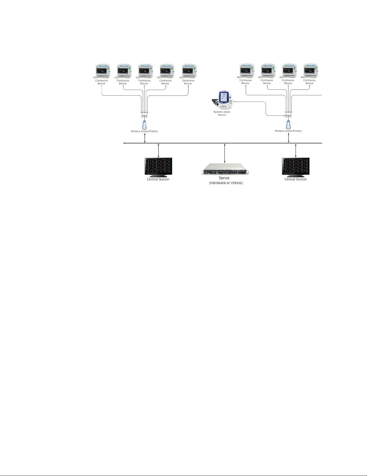
A high-level topology with multiple central stations and a Connex server is shown
in“Figure 3-1: Multiple Connex CS conceptual model” below. Although all devices are
shown with wireless communication, a wired-networking model may also be used.
Page 18
12 Overview and System Hardware Welch Allyn
Figure 3-1: Multiple Connex CS conceptual model
Page 19
Connex CS Admin Guide Overview and System Hardware 13
Central Station Computer Controls and Connectors
1. Review “Figure 3-2: Central Station computer front panel controls and connectors”
and “Figure 3-3: Central Station computer rear panel connectors” on page 14.
2. Familiarize yourself with the location of all features, controls, indicators, and
connectors on the CPU.
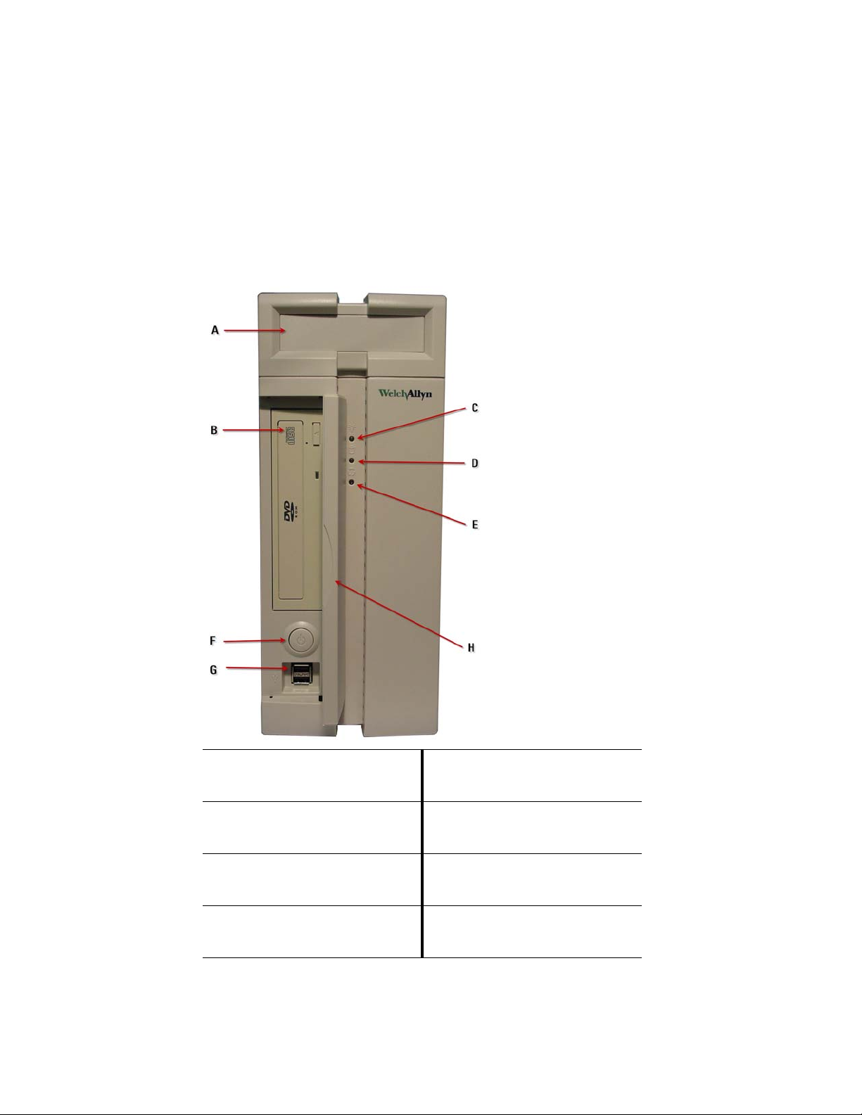
Figure 3-2: Central Station computer front panel controls and connectors
A Expansion Drive Bay (not used) E Reset switch. Press this switch to
reset the computer. Recessed to
prevent accidental activation.
B Optical drive bay (CD / DVD) F Power Switch. Press and release
to turn on the CPU. Push and hold
to turn off.
C Power LED. Turns Green when
computer is on, and is Off when
computer is not on.
D Hard disk LED. Turns on when the
computer read or writes data to
the hard disk.
G Front Panel USB ports (Qty. 2)
H Front door. Keep closed during
normal usage.
Page 20
14 Overview and System Hardware Welch Allyn
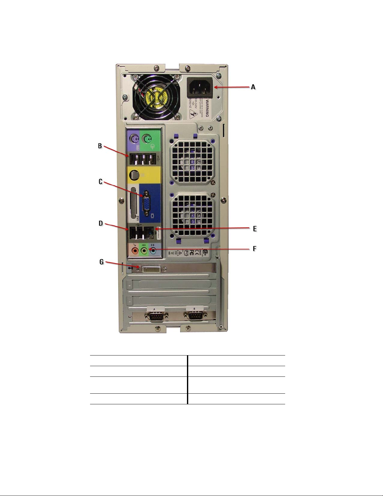
Figure 3-3: Central Station computer rear panel connectors
A AC Power inlet (100 - 240 VAC) E Network RJ45
B USB 2.0 ports (Qty. 4) F Audio out (Green)
C On-board video HD15 - DO NOT
USE
D USB 2.0 ports (Qty. 2)
G DMS-59 Video connector
Page 21
Connex CS Admin Guide Overview and System Hardware 15
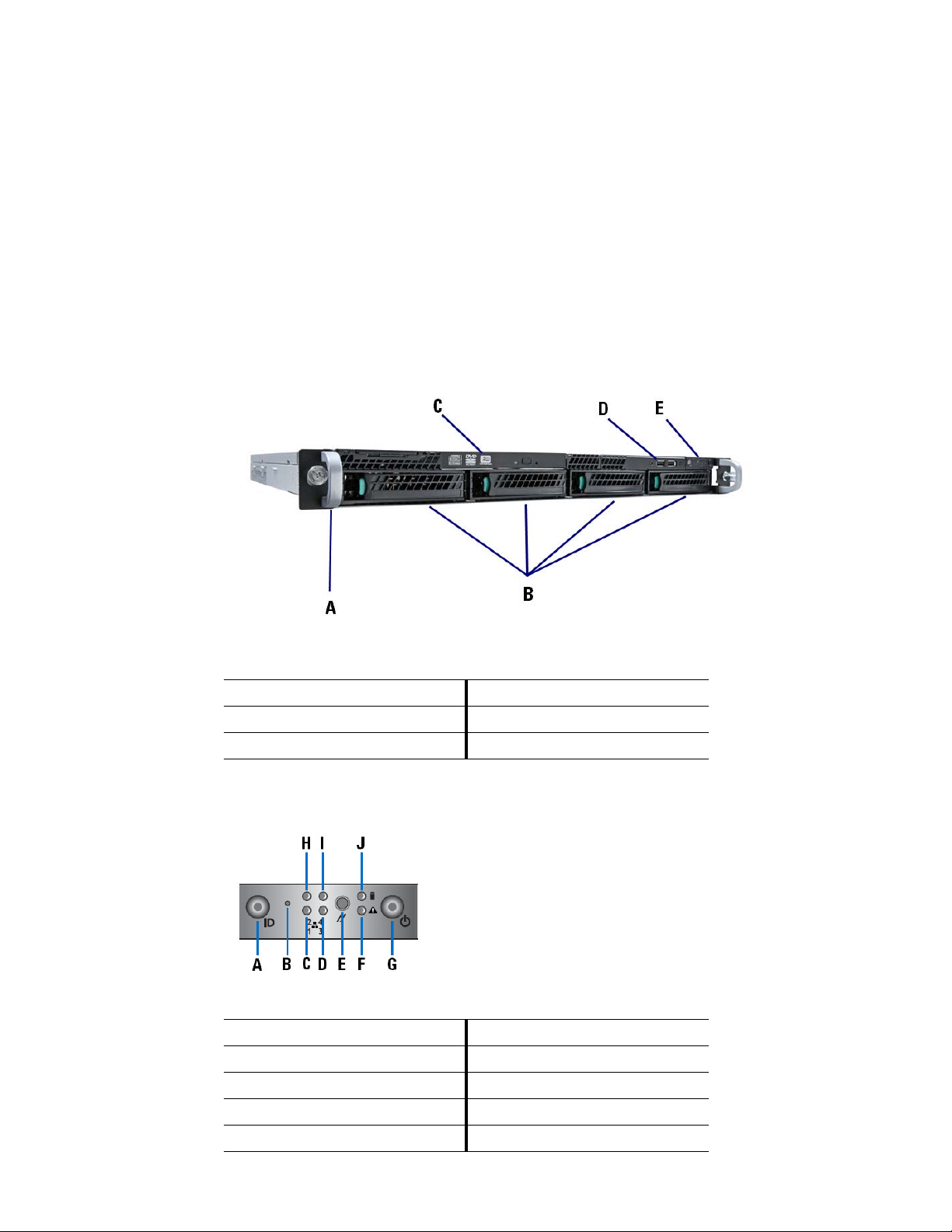
Hardware Connex Server Computer Controls and Connectors
1. Review “Figure 3-4: Hardware Connex Server Computer front panel features and
connectors”, “Figure 3-5: Hardware Connex Server Computer front panel
controls”below, and “Figure 3-6: Hardware Connex Server Computer rear panel
connectors” on page 16.
2. Familiarize yourself with the location of
connectors on the Connex server hardware.
Figure 3-4: Hardware Connex Server Compute
A Rack handles (2) D USB Ports
B Hard drive bays E Front panel controls
C Slimline optical drive (optional)
all features, controls, indicators, and
r front panel features and connectors
Figure 3-5: Hardware Connex Server Computer front panel controls
A Unstuffable ID button with ID LED F Status / Fault LED
B NMI Button (recessed) G Power Button with LED
C LAN1 LED H LAN2 LED
D LAN3 LED I LAN4 LED
E Reset Button J HDD LED
Page 22
16 Overview and System Hardware Welch Allyn
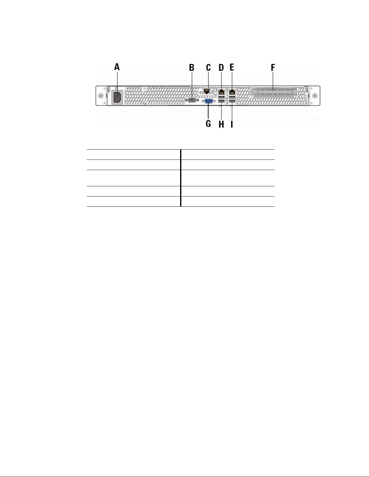
Figure 3-6: Hardware Connex Server Computer rear panel connectors
A AC Power inlet (100 - 240 VAC) F PCI Express slot
B Serial port A G Video connector
C Service Mgmt network interface
(BMC)
D NIC 1 Connector (10/100/1000 Mb) I USB Ports
E NIC 2 Connector (10/100/1000 Mb)
H USB Ports
Page 23

17
4
Central Station Startup
Different startup
Depending on the system configuration from manufacturing, the computer may be
configured as a networked central station with a shared Connex server, a warm spare
station, or a stand-alone central station. The station behavior at startup differs based on
the configuration.
Networked environment (Client / Server) considerations
In the networked environment, where there is a Connex server, it is preferred that the
Connex server be started first. The Connex server hosts the main database that all central
stations attempt to synchronize with on startup, using the Welch Allyn Connex Data
Synchronization Service. Refer to the Connex CS Server Install Guide for additional
information and startup behavior for the Connex server.
A central station configured as part of a network (client-server) model will startup with the
central station application and run by itself, but may take much longer during the startup
process if the Connex server is unreachable. The central station may also be running in a
degraded mode until the Connex server is brought online (e.g ADT services may not be
available).
Warm Spare station considerations
A system configured for Warm Spare operation is licensed and configured to contact and
synchronize its local database with that of the Connex server. The Warm Spare does not
perform any other functions than to maintain a state of readiness to be put into place as a
replacement central station when needed. Refer to “Standard central station startup” on
page 19 below startup behavior of a Warm Spare station.
A Warm Spare is part of a network environment, with a closet sever as well. It is preferred
that the Connex server be started first. Central stations, including a warm spare should be
started after the Connex server is running. Refer to the Connex CS Server Install Guide
for additional information and startup behavior for the Connex server.
Stand-alone central station considerations
In the stand-alone central station, all required services are self contained within the CPU.
Thus, there are no other systems to consider in terms of startup order. Stand-alone
stations do not have communication ability with the facility’s EMR application.
Page 24

18 Central Station Startup Welch Allyn
Power on the system
Once all peripheral items have been attached to the central station CPU, and the Connex
server installation is running (if applicable), complete these final steps to finish the install.
1. Ensure that all components are connected to a AC power outlet.
2. Power on the displays and any other peripherals which require power.
3. Turn the power ON for the CPU using the power control switch on the front bezel. The
ower On Self Test (POST) runs and displays a message on the screen.
P
4. On the main CPU, verify the following:
LED Indicator - front bezel State or Condition
Power LED. Glows a constant GREEN
Hard drive LED Turns on after POST and CPU
wh
en on.
attempts to boot.
Page 25
Connex CS Admin Guide Central Station Startup 19
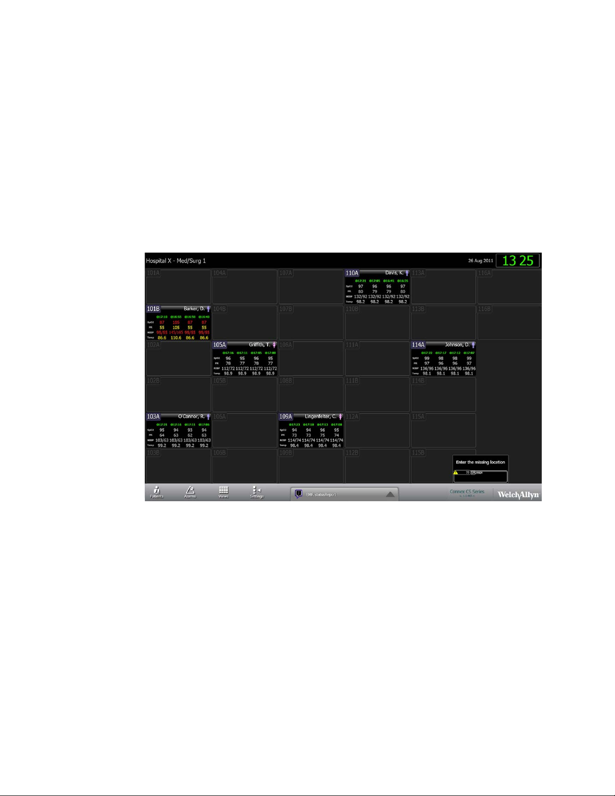
Standard central station startup
1. If properly configured, the central station should automatically startup with the
Connex CS application running.
2. Upon successful start-up of the Connex CS application, the main screen is displayed.
e“Figure 4-1: Connex CS main screen example”below.
Se
3. Some additional configuration may be required on site. Refer to other chapters in this
al for additional information subjects related to configuration and localization.
manu
4. Refer to Appendix A “Troubleshooting” o
with starting up the Connex CS Central Station CPU.
Figure 4-1: Connex CS main screen example
n page 125 if problems are encountered
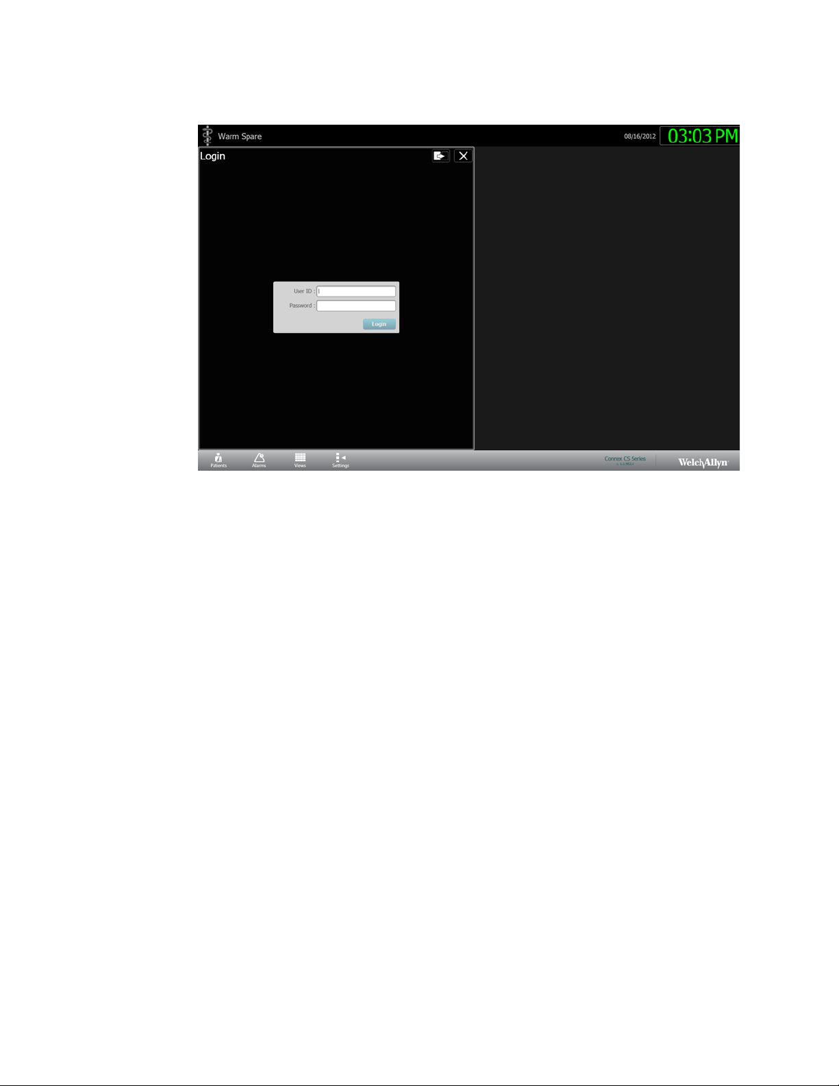
Warm Spare station startup
If the station is configured as a Warm Spare:
1. Upon successful start-up of the Connex CS application, the Warm Spare screen is
disp
layed. An example is shown in “Figure 4-2: Warm Spare main screen example”.
2. With the exception of print driv
required beyond this point.
a. Print drivers may be required to work with customer supplied printers. Refer to
“Network, Printer, Time & Date config.” on page 29 for additional information on
installing print drivers.
ers installation, typically no additional configuration is
Page 26
20 Central Station Startup Welch Allyn
Figure 4-2: Warm Spare main screen example
3. Refer to Appendix A “Troubleshooting” on page 125 if problems are encountered
with starting up the Connex CS Central Station CPU.
Page 27
21
5
Connex Server Startup
Server bootup screens
If Virtual Connex server has been installed, skip ahead to Step 8 at Windows Server
startup.
If a Hardware Connex server has been installed, follow all steps below.
1. Press the power button on the right side front bezel control panel of the server to
restart.
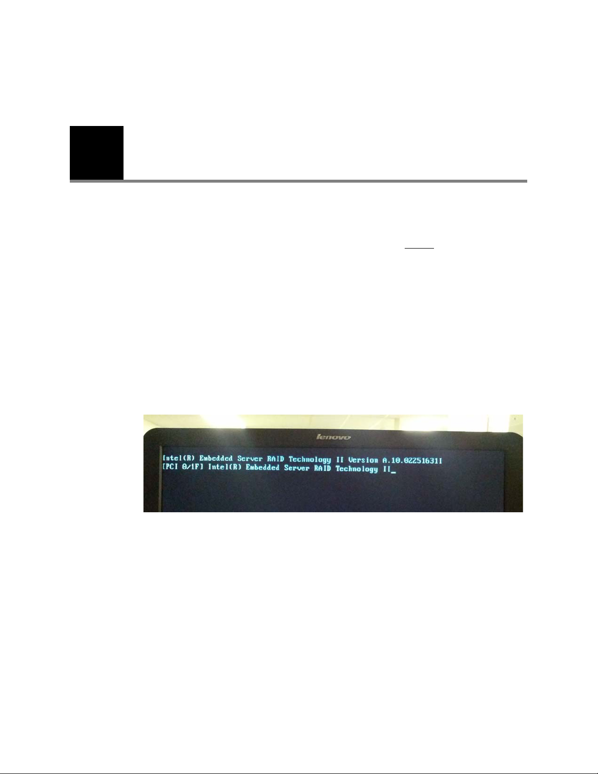
2. During normal startup, the server displays a number of bootup screens. The screen
emains blank for about 15 - 20 seconds, after which the Embedded RAID Controller
r
startup screen appears. An example is shown in “Figure 5-1: Bootup screen with
Embedded Server RAID startup”.
Figure 5-1: Bootup screen with Em
bedded Server RAID startup
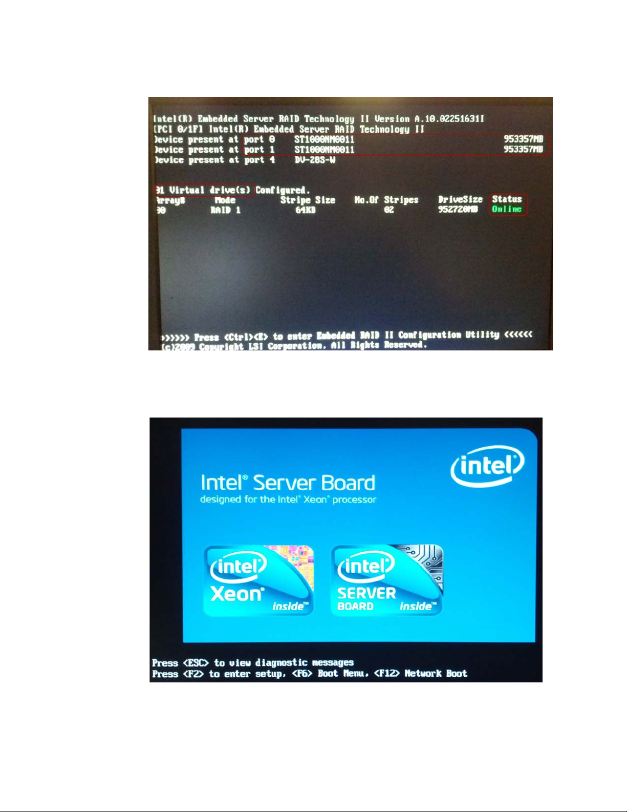
3. The screen above remains for about 20 seconds, and is then updated with the current
state RAID information.
4. For normal operation, RAID screens present at least 2 drives present in port 0 and 1.
n the example shown in “Figure 5-2: Embedded Server RAID with status display” on
I
page 22, both port 0 and 1 are populated with drives reporting is size as about 953
GB.
5. The Virtual drive is configured as Online. This is the normal state.
Page 28
22 Connex Server Startup Welch Allyn
Figure 5-2: Embedded Server RAID with status display
6. After a few seconds, the display updates to the Intel Server Board screen. An
example is shown in “Figure 5-3: System startup display with blue Intel logo”.
Figure 5-3: System startup di
splay with blue Intel logo
7. Do not press any keys unless entering maintenance modes.
8. After a short pause, the display updates and the Windows Server 2008 operating
sy
stem begins to load. The animated Microsoft logo appears.
Page 29
Connex CS Admin Guide Connex Server Startup 23
9. Once the operating system startup is complete the administrator login screen
appears.
10. Startup process is now complete. Observe the operational state as continues below.
Confirm Connex Server operational state
1. Login to the server with the Administrator account user name and password.
2. Upon success, the desktop screen is displayed.
3. On the desktop, double-click on
a. If the icon is not present, go to Star
Admin Tools Launcher > (version number) to locate the program. Right-click on
Welch Allyn Admin Tools Launcher and select Send to > Desktop (create
shortcut) to send a shortcut to the desktop.
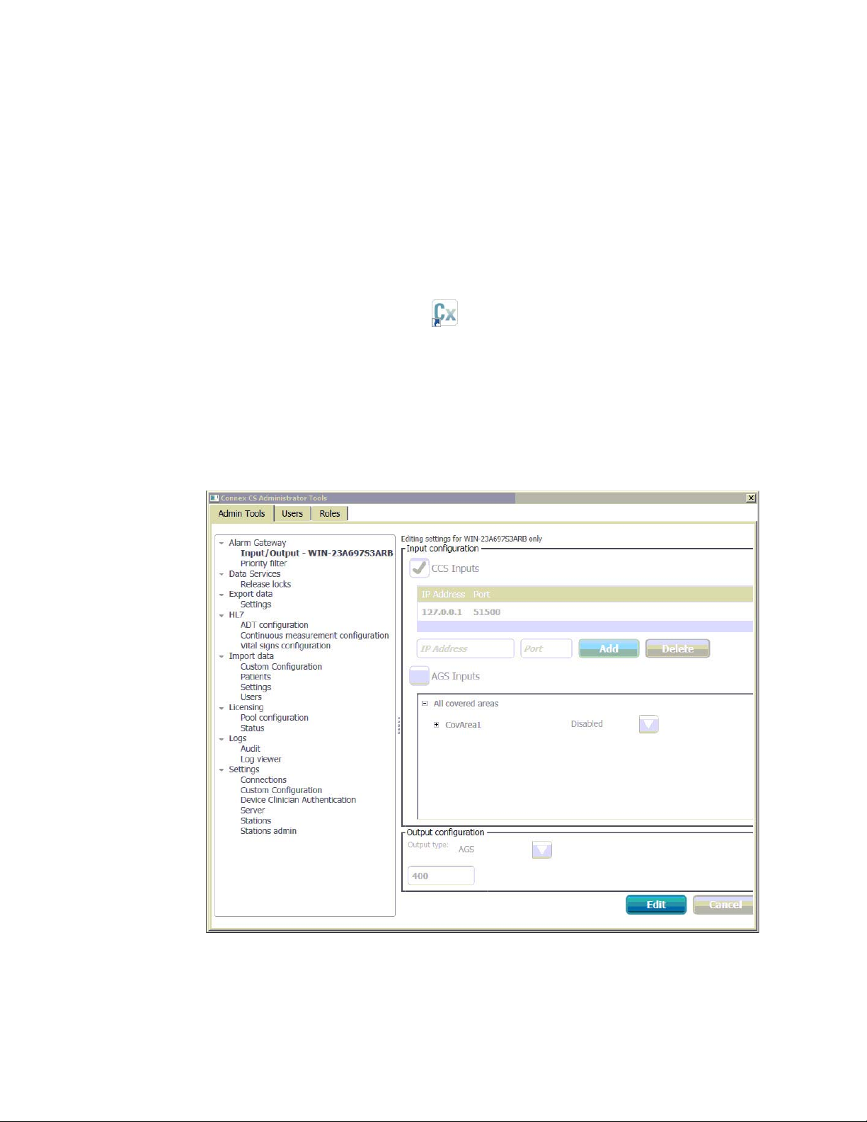
4. The Connex CS Administrator Tools is similar to the Set
needed) > Admin tools tab window on the workstation. An example is shown below.
Figure 5-4: Administrator Tools startup window
. The Connex CS Admin Tools function launches.
t > All Programs > Welch Allyn > Connex >
tings > Advanced settings (if
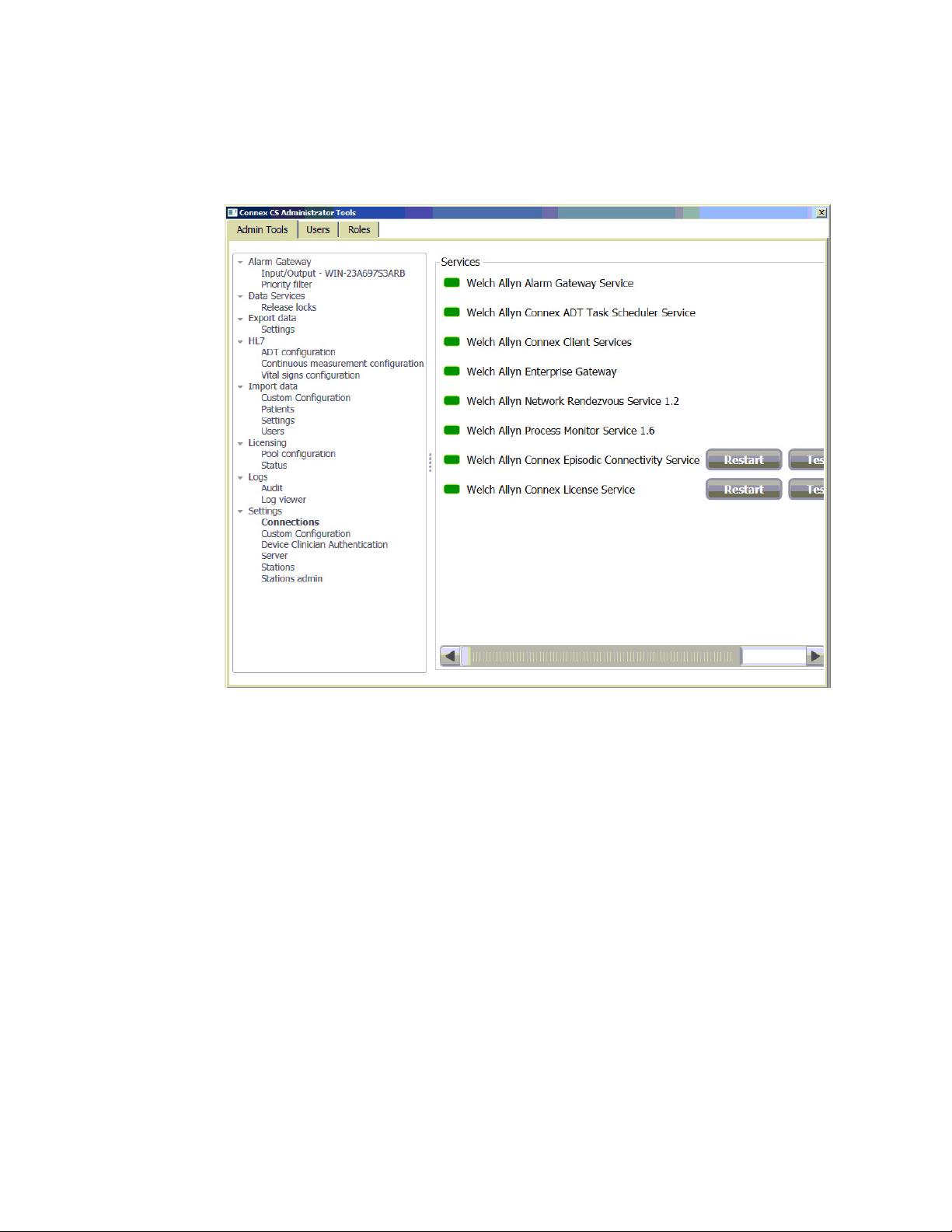
5. On the Admin Tools tab, navigate to Settings > Connections. The Services windows
displays the state of all of the core services running which make up the Connex
Server application. An example is shown below in “Figure 5-5: Administrator Tools
setting connections window” on
page 24.
Page 30
24 Connex Server Startup Welch Allyn
Note
6. A green state means that the service is currently running normally.
7. A re
d state means that the service is not running in a normal state or has stopped.
Figure 5-5: Administrator Tools setting connections window
8. If more than one service needs to be restarted, it is recommended all services be
restarted in a specific sequence.
To restart multiple services:
a. Proceed by clicking on the Restar
t button associated with each service in the
following sequence:
• Client Services
• License Service
• Enterprise Gateway service
• Episodic Connectivity Service
• Alarm Gateway Service
• ADT Task Scheduler Service
• Network Rendezvous Service
• Process Monitor Service.
b. The Services present in the working window depend on the features and licenses
purchased.
Some Services may not be present on previous versions of Connex CS.
c. If one or more services cannot be restarted successfully, refer to
“Troubleshooting” o
n page 125 for additional information.
Page 31

Connex CS Admin Guide Connex Server Startup 25
Confirm communication with central stations
1. Ensure that all central stations have been installed and are reachable on the network.
2. Open a command tool and ping each host by it’s assigned IP address. Refer to the
Co
nnex CS Customer Project Req. Form, Appendix B1 as needed.
3. On the server, open the Administration Tools again.
4. On the Admin tools tab, navigate to Li
Covered Area central stations and their respective licensing allocations. An example is
shown below.
Figure 5-6: Administrator Tools licence pool configuration window
censing > Pool Configuration to view the
5. Confirm that all central stations installed on the network have a column present with
the Covered Area name displaying in the Per Covered Area Licenses window.
a. In the above example, there are two Covered Areas shown, 6 South and 4 South.
b. Licenses are allocated to both Covered Areas but with differing quantities.
Confirm communication with EMR
If the server is configured for interface with the facility’s EMR application, via HL7
messaging, perform these checks. Refer to the Connex CS Customer Project Req.
Form for configuration settings of HL7 messaging options for both ADT inbound and ORU
outbound workflows.
Page 32

26 Connex Server Startup Welch Allyn
To launch the Corepoint Administration console:
1. G o t o Star
t > Programs > Corepoint Integration Engine > Administration to start
the administration console within an Internet Explorer browser window.
2. Login with user name and password.
3. Click on Conn
ections tab near the top left of the window to view current connection
states. An example is shown below.
Figure 5-7: Corepoint administration console connections initial view
4. Some simple view changes may provide a simpler way to view connection data.
a. The typical view displays connections in te
rms of grouping. As the application is
only being used with Connex, the grouping view contains additional information
which is not needed.
b. In the drop down menu next to Grouping, select the option for No
c. Click on
in the upper right corner to customize the columns to view. A drop
Groups.
down menu appears.
d. Items selected for view have a ✓ ne
xt to them are selected for inclusion in the
view.
e. Use the drop down menu and select Backlog to remove.
f. Use the drop down menu and select Peer and Port to add.
g. An updated view example is shown in “Figure 5-8: Corepoint administration
console connections updated view” o
h. The next time the administration console is ac
n page 27 below.
cessed, it will retain the last know
view.
Page 33

Connex CS Admin Guide Connex Server Startup 27
Figure 5-8: Corepoint administration console connections updated view
5. Observe the items in the first column, Connection Name.
6. The color of a connection indicates its c
urrent state. A summary of some common
states are shown in “Table 5-1: Connection states” below.
Table 5-1: Connection states
Connected
In the process of connecting
Not connected
Stopped, in the process of stopping, or restarting
Waiting on an acknowledgement (ACK)
7. Connection names are related to the functions they serve. A typical list of
connections which connect to the facility’s EMR application (external to Connex CS) is
described in “Table 5-2: External EMR facing con
nection names and functions,
typical”.
Page 34

28 Connex Server Startup Welch Allyn
Note
Table 5-2: External EMR facing connection names and functions, typical
WA_ADT_IB Inbound ADT between facility HIS and Corepoint (External)
WA_ORU_OB_UNCONFIRMED Outbound ORU unconfirmed data between Corepoint and facility HIS (External)
WA_ORU_OB_CONFIRMED Outbound ORU confirmed data between Corepoint and facility HIS (External)
Connections names may appear differently on your system from those shown in
the examples, as interfaces are customized based on facility needs and options
purchased.Refer to the Connex CS HL7 Interface Guide for additional
information.
8. A number of internal connections to the Corepoint application are also observed on
the connections page. A typical list of connections which connect to other systems
and processes in the Connex CS application (internal to Connex CS) is described in
“Table 5-3: Internal Welch ALlyn facing connection names and functions”.
Table 5-3: Internal Welch ALlyn facing connection names and functions
WA_ADT_OB Outbound ADT data between Corepoint and Connex server (Internal)
WA_ORU_IB_CONTINUOUS1 Inbound Continuous ORU data between Central Station 1 and Connex (Internal)
WA_ORU_IB_CONTINUOUS2 Inbound Continuous ORU data between Central Station 2 and Connex (Internal)
WA_ORU_IB_EPISODIC Inbound Episodic ORU data between Connex server and Corepoint (Internal)
9. In the above example shown in “Figure 5-8: Corepoint administration console
connections updated view” o
WA_ADT_OB are both green or connected. This is the minimum state that should be
esent for ADT connections.
pr
a. The WA_ADT_IB connection may be shown in y
Corepoint and the facility HIS has not been established.
n page 27, the connections for WA_ADT_IB and the
ellow if an interface between
Apply Customer Provided MSSQL Standard Licence Key
New Connex Servers (hardware or virtual) ship with a temporary MSSQL key that must be
changed to use a customer supplied key prior to using the Connex Server in a production
environment. Follow the steps detailed in “Apply your MSSQL Standard License Key to
the Connex Server” on page 160 for specific instructions.
Page 35

29
Note
6
Network, Printer, Time & Date config.
Connex CS Shell versus Windows Shell
The Connex Central Station is intended and designed to support automatic startup of the
Connex CS application when the CPU starts. To support this, the system is configured to
operate in the Connex CS Shell mode. This shell mode blocks general users access to
Windows functions, such as the Windows key, Ctrl+Alt+Delete, and Alt+Tab.
Windows functions are accessible from a command line tool built into the Settings tools,
and described within this chapter.
It is recommended to make network changes, such as IP address settings, with
the system configured for Windows shell.
To change the shell mode:
1. On the navigation area, click on Settings > Advanced settings (if required). The login
screen appears.
2. Login using your User ID and Password information. Upon success the Settings
window appears.
3. Click on the Service Tools tab.
4. Click on Shell. The shell mode window appears. Select Edit to make changes. An
example is shown below in
page 30.
5. Select the desired shell by clicking on the corresponding radio button.
6. It is also desirable to deselect the check box next to Disable Windows and
Ctrl+Alt+Delete keys if the system will be operating in Windows shell for
configuration or maintenance activities.
7. Click Save when done. A confirmation window appears.
•Select Ye s to save changes and reboot now.
•Select No to save changes without reboot.
•Select Cancel to continue without saving changes.
8. Upon restart, the system starts with a normal PC Windows desktop display after
login.
9. When all work in the Windows shell is complete, revert the system back to Connex
CS shell prior to clinical usage.
“Figure 6-1: Shell mode configuration screen example” on
Page 36

30 Network, Printer, Time & Date config. Welch Allyn
Figure 6-1: Shell mode configuration screen example
Network Changes
The change in the IP Address of one or more systems involved in Connex CS network will
cause many components to break. This requires updating the specific configurations in
the system used by such components.
Due to complexity of these level of changes, these scenarios are best managed by trained
Welch Allyn staff, and may require planning for down-time. Please consult with your
Welch Allyn Project Manager or Technical Support for additional information.
Page 37

Connex CS Admin Guide Network, Printer, Time & Date config. 31
Note
Add a Customer Supplied Printer
It may be necessary to add a printer on-site, especially in the case of using a customer
provided or shared network printer.
It is the facility responsibility to provide a driver for the printer.
Consult with the facility IT staff to identify the network printer and obtain a driver
compatible with Windows 7 - 64 bit. Refer to the Connex CS Customer Project
Req. Form for network information.
To install a printer on the central station:
1. Ensure the printer is turned on and accessible on the network.
2. Open a command line interface window and ping the printer by the IP address to
confirm that it is reachable.
3. Install the print driver provided by the facility.
a. Use the Connex server internal CD/DVD ROM drive for optical media.
b. Use one of the USB ports on the front panel for USB flash drive media.
Install print driver from an executable.EXE file
1. If the customer has provided CD/DVD media which will automatically run, follow the
steps and prompts as provided.
2. If the customer has provided media with an .exe file type, double click on the file to
start the installer. Follow the steps and prompts as provided.
Install print driver from a media with an .INF file
Use the Windows functions to Add a printer:
1. Click Start > Control Panel > View devices and printers.
2. Click on Add a printer.
3. Select Add a network, wireless, or Bluetooth printer.
4. Windows being a search for known printers.
If the desired printer is found using search:
1. Select Stop when the printer appears in the search window.
2. Click on the printer, and then select Next.
3. Change the name of the printer as desired and select Next.
4. For printer sharing, select an option and then select Next.
5. Select Print a test page. and then select Finish.
6. Confirm that a test print was printed by the printer.
7. The printer appears in the Control Panel Printers and Faxes window.
Page 38

32 Network, Printer, Time & Date config. Welch Allyn
If the printer was not found using search:
1. Click The printer that I want isn’t listed.
2. Select the radio button next to Add a printer using a TCP/IP address or hostname,
and then select Next.
3. Leave Device type as Autodetect.
4. Enter the IP address of the printer.
5. Ignore the Port name, and select Next.
6. Select the printer manufacturer and model from the menus.
7. If the printer is not listed, select Have Disk, and browse to the location of the .INF
driver file. Select OK when ready.
8. Click on the printer, and then select Next.
9. Change the name of the printer as desired and select Next.
10. For printer sharing, select an option and then select Next.
11. S el ec t Print a test page. and then select Finish.
12. Confirm that a test print was printed by the printer.
13. The printer appears in the Control Panel Printers and Faxes window.
14. If more than one printer is installed, choose a printer to set as the default.
Change Date, Time, and Time zone
It may become necessary to adjust the date and time to local settings. Use standard
Windows control functions to adjust the date, time, and time zone settings as necessary.
Caution Date, time, and time zone settings must be set identical on the Central
Station, Connex server, and attached devices. If time, date, and time zone
settings are not the same, devices may not be able to communicate with the
Central Station or Connex server.
1. For a standalone Central Station, not installed on a domain, the Internet Time tab will
be available.
a. Click on Internet time > Change settings.
b. Click on Synchronize with an Internet time server.
c. Use the drop down list to select time.nist.gov.
d. Click Update now and confirm that the time is updated within shortly.
2. Click OK, and apply all changes when finished.
3. For a network that includes a Central Station, and Connex server, refer to “Time
Synchronization” on page 10 3 for additional information as needed.
Page 39

33
Note
Note
7
Backup & Restore
Backup users and configuration
The Administration tool tab has functionality to backup and restore configuration
information for the system and users. Tasks may be completed at any workstation or the
Connex server, and only needs to be done once for the entire network of central stations
and Connex server.
The export data and settings functions described in this section create an output
of a single XML file, where all information is combined. In some situations it may
also be desirable to create separate export (backup) files User Account Settings
and Server Configuration Settings.
To make a local backup of Connex CS users and configuration information:
1. Insert a USB flash drive into one of the USB ports on the CPU front panel.
2. On the navigation area, click on Settings. The login screen appears.
3. Login using your administration account User ID and Password information. Upon
success the Settings window appears.
4. Select the Admin tools tab > Export data > Settings. The Settings window appears.
An example is shown in
window” on page 34.
“Figure 7-1: Export data settings users and configuration
Select User Account Settings and/ or Server Configuration Settings per desired.
If both Users and Configurations are selected, the output will be combined in to a
single XML file. In some situations it may also be desirable to create separate
export (backup) files User Account Settings and Server Configuration Settings.
Page 40

34 Backup & Restore Welch Allyn
Figure 7-1: Export data settings users and configuration window
1. Select Export data.
2. Navigate to the USB flash drive. Choose a folder location for the backup.
3. Chose a file name for the saved file. By
default, the file will be called
WAConfigurationSettings.xml, but should be changed to the following format for
consistency:
• System S/N . Backup type. Country or State . Facility Name . Covered Area .
te
Da
• An example – CN01087.config&users.NY.CrouseHospit
4. Also save a local copy on the sy
stem at the following location:
al.AllHosts.2012.08.09.xml
Page 41

Connex CS Admin Guide Backup & Restore 35
Note
• C:\ProgramData\Welchallyn\@Config.Backup.
ProgramData is typically a hidden file. You may need to type location by hand into
the folder location bar using the keyboard.
The folder @Config.Backup may not exist if this is a new installation. Create this
folder as necessary.
5. Upon success, click OK.
Nightly System Backup
By default, all Connex CS system computers are configured to backup their database to a
local source (same host) at approximately 12:00 am (midnight).
The Connex Data Backup runs on stand-alone Central Stations and Servers.
For stand-alone Central Stations, database backups can be found at the following location
in the file system:
C:\Program Files\Microsoft SQL Server\MSSQL10_50.SQLExpress\MSSQL\Backup,
where MSSQL10_50.SQLxxx is the main SQL version installed.
For Connex server, database backups can be found at the following location in the file
system:
C:\Program Files\Microsoft SQL
Server\MSSQL10_50.SQLSTANDARD\MSSQL\Backup, where MSSQL10_50.SQLxxx is
the main SQL version installed.
Page 42

36 Backup & Restore Welch Allyn
Note
Backup Corepoint configuration - create a NIX file
Create a backup of the current Corepoint configuration which may be needed in the case
of a replacing the system hardware in the event of failure.
These steps only apply if the Closet Service is licensed and configured to support
HL7 interfaces, including ADT and/or ORU connections
1. On the Connex server, go to Star
Integration Engine > Configuration to being the configuration tool.
2. Login as Manager. The Corepoint Integration Engine Configuration tool appears.
Figure 7-2: CIE configuration tool main display with navigator window example
t > All Programs > Corepoint Health > Corepoint
3. In the navigator window, locate the Derivatives area on the left side of the window.
4. Right-click on the r
oot directory /. An example is shown below.
Page 43

Connex CS Admin Guide Backup & Restore 37
Figure 7-3: Right-click on the root to open
5. Click on Export. The export options window appears.
Figure 7-4: Corepoint export options window
6. Click on the option for Export all derivatives. Then click OK. he progress window
appears momentarily.
Figure 7-5: Corepoint export files being prepared
Page 44

38 Backup & Restore Welch Allyn
7. After a short while, the export selected components window appears.
Figure 7-6: Corepoint export select components window example
8. Leave all settings in the above window at default, with all items selected. Click OK
to proceed. The save file window appears.
Page 45

Connex CS Admin Guide Backup & Restore 39
Note
Figure 7-7: Save file window example
9. Click on Desktop to place the backup file directly on the desktop, making the backup
easy to locate if needed later.
10. Type a F
11. Chose a file name for the saved file. Follow the recommended naming schema below
to maint
• Network S/N.Corepoint.Country or State.Facility Name.Date
• An example – CN01087.Corepoint.NY.UHS-Wilson.2013.08.08
12. Also save a local copy on the system at the following location:
• C:\Pr
eave the type of file at default, as displayed in the above example (*.nix). Click Save
13. L
when ready.
14. Confir
ile name for the backup.
ain consistency:
ogramData\Welchallyn\@Config.Backup.
ProgramData is typically a hidden file. You may need to type location by hand into
the folder location bar using the keyboard.
The folder @Config.Backup may not exist if this is a new installation. Create this
folder as necessary.
m the presence of the file as displayed on the desktop.
Backup Corepoint HL7 License
1. Open a Windows Explorer window.
2. Navigate to C:\P
Engine\License.
3. Make a copy of the license file Cor
the Desktop.
rogram Files (x86)\Corepoint Health\Corepoint Integration
epointEngine.lic and place it in backup folder on
Page 46

40 Backup & Restore Welch Allyn
Note
Note
Restore Patients and Users
The Administration tool tab has functionality to backup and restore configuration
information for the system and users. Tasks may be completed at any workstation or the
Connex server, and only needs to be done once for the entire network of central stations
and Connex server.
The import patients settings and users functions described in this section restore
functions from input files previously saved or created off-line. Use care to select
the proper file for import functions (restore).
Caution Importing of patients is not used for standard clinical workflow, but is
described herein and may be used for exercise during testing or demonstration
purposes.
To restore Connex CS patients or users:
1. Insert a USB flash drive into one of the USB ports on the CPU front panel.
2. On the navigation area, click on Se
3. Login using your account User ID and P
Settings window appears.
4. Select the A
window appears. Select Browse and navigate to the import source file location. An
example is shown below in “Figure 7-8: Import data Patients list window example” on
page 41.
Patients list and Users list import functions support CSV type files only.
5. See “Creating a Patient list” on page 42 for additional information as needed
6. See “Creating a User list” on pag
7. Select the file, and select Op
8. The selected file name appears in the Import dat
Import, and confirm the select.
9. Restar
dmin tools tab > Import data > Patients or Users. The select file
t for changes to take affect.
ttings. The login screen appears.
assword information. Upon success the
e 43 for additional information as needed.
en.
a window Select file area. Select
Page 47

Connex CS Admin Guide Backup & Restore 41
Note
Figure 7-8: Import data Patients list window example
Restore Settings
The Administration tool tab has functionality to backup and restore configuration
information for the system. Tasks may be completed at any workstation or the Connex
server, and only needs to be done once for the entire network of central stations and
Connex server
To restore Connex CS settings:
1. Insert a USB flash drive into one of the USB ports on the CPU front panel.
2. On the navigation area, click on Se
3. Login using your account User ID and P
Settings window appears.
4. Select the A
appears. Select Browse and navigate to the import source file location.
Settings list import functions support XML type files only.
5. Select the file, and select Open.
6. The selected file name appears in the Impor
Import, and confirm the select.
7. Rest
art for changes to take affect.
ttings. The login screen appears.
assword information. Upon success the
dmin tools tab > Import data > Settings. The select file window
t data window Select file area. Select
Page 48

42 Backup & Restore Welch Allyn
Creating a Patient list
A patient list may be created off-line using standard office productivity software (e.g.
Microsoft Office Excel) and saved in a comma separated variable format for importing a
larger list of patients.
Caution Importing of patients is not used for standard clinical workflow, but is
described herein and may be used for exercise during testing or demonstration
purposes. Use standard ADT message communication to populate patient lists
whenever possible.
Import patients from a CSV format requires the following columns of data:
• PatientId – Contains unique identification for a patient.
• FirstName – Specifies first name of patient.
• LastName – Specifies last name of patient.
• Gender – Specifies patient gender.
• DOB(MM/dd/yyyy) – Specifies birth date of patient in “MM/dd/yyyy” format.
• Unit – Specifies unit of patient location.
• Facility – Specifies facility of patient location.
• Building – Specifies building of patient location.
• Floor – Specifies floor of patient location.
The following text block example below describes the format required within the first line,
which is also a required line at the top of the CSV file.
PatientID,FirstName,LastName,Gender,DOB(MM/dd/yyyy),Unit,Facility, Building,Floor
123456-78,Thomas,Jones,Male,05/22/1962,2MS,GeneralHospital,South,Floor2
089345-25,Jennifer,Green,Female.09/30/1946,6SIR,GeneralHostical,Irving,Floor6
Page 49

Connex CS Admin Guide Backup & Restore 43
Creating a User list
A user list may be created off-line using standard office productivity software (e.g.
Microsoft Office Excel) and saved in a comma separated variable format for importing a
larger list of users.
Import users from a CSV format requires the following columns of data:
• SettingsGroup – Specifies group for user roles.
• Suffix – Specifies suffix for user roles, includes “Jr.”, “Sr.”.
• Title – Specifies user title, includes “Dr.”, “Mr.”, “Mrs.”, “Miss”.
• UserName – Specifies user name uniquely identified throughout the application.
• ClinicianNumber – Specifies clinician number.
• FirstName – Specifies first name of user.
• MiddleName – Specifies middle name of user.
• LastName – Specifies last name of user.
• IsActive – Specifies whether user is active or not.
• PasswordChangeRequired – Specifies whether user needs to change password
while logging in for the first time.
• Clinician – Specifies whether user has “Clinician” role or not.
The following text block example below describes the format required within the first line,
which is also a required line at the top of the CSV file.
SettingsGroup,Suffix,Title,UserName,ClinicianNumber,FirstName,MiddleName,LastName,IsActive,PasswordChangeReq
uired,Clinician
Physician,Jr.,Dr.,andersoa,00105602,Thomas,A,Anderson,TRUE,TRUE,FALSE
Clinician,,,greenes,00105623,Sally,,Greene,TRUE,TRUE,TRUE
Biomed,,,jamesont,0020041,Timothy,,Jameson,TRUE,TRUE,FALSE
Nurse Manager,,,duckworm,00100921,Marsha,,Duckworth,TRUE,TRUE,TRUE
Page 50

44 Backup & Restore Welch Allyn
Page 51

45
8
Location Management
Connex CS applications are structured around a flexible hierarchy used to establish a
logical location for assignment for patients within the system. the following definitions
describe some of the functions and relationship of each within the hierarchy.
Item Description
Station An logical system that can be used to service a covered area
Master Bed List A complete list of all available beds to be managed by Connex. In a stand-alone system, all
beds are known to the single central station. In a multi-system environment, all beds are
known to the server.
Covered Area A grouping of beds from the master list that can be covered or monitored by a Connex CS
central station. Each central station is configured to support a single covered area.
Warm Spare An installation of Connex CS application software that has not yet been configured or
assigned to a station.
Host A physical computer (PC) on which the Connex CS workstation application software is
installed.
Caution Making changes to settings in Location Management may cause
interruptions in patient monitoring. Do not change Location Management
settings without contacting Welch Allyn technical support. These steps are
informational only, and included to support your understanding of the current
system configuration.
Add a Station
Though generally not the case, stations can exist and be configured without being applied
to a host computer.
To add a station:
1. On the navigation area, click on Settings. The login screen appears.
2. Login using your assigned administrative level account User ID and Password
information. Upon success the Settings window appears.
3. Select the Admin tools tab. From the left side menu, select Stations, nested under
Settings.
4. Select Location management. The Location management window appears. An
example is shown below in
page 46.
“Figure 8-1: Location management window example” on
Page 52

46 Location Management Welch Allyn
Figure 8-1: Location management window example
5. Click on Stations. The Stations window appears.
6. To add a station, first click on Ed
7. To add a new station, click in the A
it near the bottom of the window.
dd station field and type a name for the station.
Refer to the Connex CS Customer Project Req. Form, Appendix B2 as needed to
determine the proper entry for the station.
Figure 8-2: Add Station window
8. Click Add when finished. The station name now appears in the Stations window by
name. An example is shown below in “Figure 8-3: Newly added station example” on
page 47.
Page 53

Connex CS Admin Guide Location Management 47
Figure 8-3: Newly added station example
9. Click Save when finished.
10. Click on the Bac
k button in the window header.
Page 54

48 Location Management Welch Allyn
Add a Master bed list
Within the master bed list exists another hierarchy structure for rooms and beds. All
locations with Connex CS are defined by their names for Facility, Building, Floor, Unit,
Room and Bed.
Caution Any time changes are made to the Master Bed List, Covered Area, or
Licensing, the affected Central Station should be restarted prior to clinical usage.
To add a master bed list:
1. From the Se
Location management menu, click on Master bed list. The Master bed list window
appears. An example is show below in Figure 5-5.
Figure 8-4: Master bed list default window example
ttings > Advanced settings (if required) > Admin tools > Stations >
2. Observe that there are two sub-windows within the Master bed list main window.
3. Click on Ed
it near the bottom of the window.
Page 55

Connex CS Admin Guide Location Management 49
4. Create a new Master bed list if there are no Units present.
Caution Fie
appear on the Central Station and associated patient monitors. In a networked
environment with more than one Central Station, the Master bed list controls
this information for all systems. Always refer to the Connex CS Customer
Project Req. Form when entering information in these fields.
Caution If the s
application, location fields for Facility, Building, Floor, and Unit must match
exactly with the ADT messages. Use a dash “-” to denote a null field if the
facility’s ADT feed does not send specific data. Data mis-matches in these
location fields will result in no patients appearing in the Connex CS
application Patient List.
Create a New Unit
1. In the Units window, click in the Facility field and enter the facility name.
2. Continue for the Building, Floor, an
“Figure 8-5: Facility, Building, Floor and Unit entry field examples”.
3. When finished, click Ad
“Figure 8-6: Newly created Unit example” below.
Figure 8-5: Facility, Building, Floor and Unit entry field examples
lds in the Master bed list control which units, rooms, and beds
ystem is configured with an ADT interface to the facility’s EMR
d Unit fields. An example is shown below in
d. A new entry for the Unit appears in the Units window. See
Figure 8-6: Newly created Unit example
Page 56

50 Location Management Welch Allyn
Note
Note
Add a New Room and Bed
In the Units window, click on the newly created Unit name, 3SMS in the above example.
The Unit name appears in the header for the lower Room and Bed windows.
There are a number of different methods that can be used to add a room and bed
including:
• Add a single room and bed.
• Add a range of rooms and beds.
• Change room and bed values.
• Copy rooms and beds info from a CSV file.
To add a single room and bed:
1. In the Master bed list window, click Ed
2. Click in the Room
3. Click in the Bed fie
Figure 8-7: Single Room and Bed entry fields example
4. Click Add. Then new room and bed information appear in the respective fields.
field and enter a Room number.
ld and enter a Bed name. See Figure 5-8 for an example.
it to make changes.
5. Repeat steps 1 through 3 to additional rooms and beds. See Figure 5-9 for an
ex
ample.
Rooms and beds will be displayed in descending order, not the order in which
they were entered.
Rooms and beds will be displayed in descending order for the Unit, not the order
in which they were entered
6. Click Save when finished.
Page 57

Connex CS Admin Guide Location Management 51
Figure 8-8: Newly added Room and Bed examples
Page 58

52 Location Management Welch Allyn
Note
To Add a Range of Rooms and Beds
1. In the Master bed list window, click Ed
2. Click on the ex
pander to the left of Advanced options. Two additional windows
it to make changes.
appear. An example is shown in Figure 5-10.
Figure 8-9: Advanced options default
3. Click in the Room Start field to enter the first room number of a range.
4. Click in the Room En
5. Click in the Bed Star
6. Click in the Bed End
d field to enter the last room number of a range.
t field to enter the first bed name of the range.
field to enter the last bed name of the range. An example is
shown in Figure 5-11.
Figure 8-10: Advanced options default
7. Click Add range when finished. The new range of beds and rooms appears in the list.
Ranges of beds and rooms must be continuous. The Add range function may be
used as many times as needed. Single rooms and beds may be specified by using
the same start and end value (i.e. Room 318 - 318).
8. Click Save when finished.
Page 59

Connex CS Admin Guide Location Management 53
Note
Note
To change Room or Bed values:
1. In the Master bed list window, click Ed
it to make changes.
When making changes to rooms and beds ensure that the bed is not currently in
use or assigned to a patient.
2. If corrections are needed to a room value, click on the room to be changed and then
click Delete.
3. A pop-up window appears asking to c
onfirm the removal. Click Ye s to confirm the
removal, or No to cancel.
4. Re-enter the room and bed information as needed.
Removal of a room with more than one bed will also all remove associated beds.
5. If corrections are needed to a single bed value, click on the room and bed to be
changed and then click Delete.
6. A pop-up window appears asking to c
onfirm the removal. Click Ye s to confirm the
removal, or No to cancel.
7. Re-enter room and bed information as needed.
Page 60

54 Location Management Welch Allyn
To copy from a CSV file to add rooms and beds
This feature is available beginning in Connex CS v1.2 and higher.
1. In the Master bed list window, click Ed
2. Click on the ex
pander to the left of Advanced options.
3. Continue to scroll down to the bottom of the window.The Cop
it to make changes.
y and paste from a
CSV file window is viewable. An example is shown in “Figure 8-11: CSV entry fields
available in advanced options”
Figure 8-11: CSV entry fields available in advanced options
Page 61

Connex CS Admin Guide Location Management 55
4. Click on the gray text within the CSV file window.
5. Copy and paste room and bed information from a CSV file into the window. An
e
xample is shown in “Figure 8-12: Copy and paste from CSV file window with data
example” o
a. Alternately type room and bed info directly into the window.
n page 55.
Figure 8-12: Copy and paste from CSV file window with data example
6. Click Add to add the rooms and beds to the unit.
7. Click Sa
When complete...
1. Confirm that all information listed in the Master bed list is complete, and matches the
b. Text should be of the format ro
c. Type r
d. The use of the comma in the room or bed file name is not allowed.
information contained in the Connex CS Customer Project Req. Form.
oom info only as in the case of a single bed room with bed name.
ve when finished.
om,bed with no spaces.
2. Click Sa
3. Click on the Bac
appears.
ve when finished.
Caution An
Licensing, the affected Central Station should be restarted prior to clinical usage.
k button in the window header. The Location management menu
y time changes are made to the Master Bed List, Covered Area, or
Page 62

56 Location Management Welch Allyn
Add a Covered area
The Covered area window contains configuration tools that bind all of the previously
entered location information together with a station. The process described in this section
includes:
• Add a new covered area
• Assign default location
• Assign bed to the covered area
• Assign a station to the covered area.
The binding of a covered area and specific bed locations to a specific station name
together completes the configuration of location management settings prior to deploying
to a host.
Caution Any time changes are made to the Master Bed List, Covered Area, or
Licensing, the affected Central Station should be restarted prior to clinical usage.
To g e t s t a r t e d :
1. From the Settings > Advanced settings (if required)> Admin tools > Stations >
Location management menu, click on Covered Areas. The Covered areas window
appears. An example is show below in
example”.
“Figure 8-13: Master bed list default window
Page 63

Connex CS Admin Guide Location Management 57
Figure 8-13: Master bed list default window example
2. Observe that there are four sub-windows within the Covered areas main window.
3. Click on Ed
it near the bottom of the window.
4. Create a new covered area if there are none present.
Caution T
he covered area name will appear in the upper left corner of the
Connex CS display screen. Always refer to the Connex CS Customer Project
Req. Form when entering information in these fields.
5. Click in the Ent
er new covered area field and enter the covered area name. An
example is shown in “Figure 8-14: Add covered area example”.
Figure 8-14: Add covered area example
6. Click Add when finished. The newly create covered area appears above in the
Covered areas window by name.
Page 64

58 Location Management Welch Allyn
Note
Note
7. Click on the new covered area, 3 South in this example, and click on Mark as default
if this is the default system for the network. See “Figure 8-15: Covered areas window
example” for an example.
The default covered area provides a setting for all new devices to connect to the
network for the first time, prior to being assigned to a location. There can be only
one default covered area for a network. For a stand-alone central station, where
there is only a single covered area, always mark the covered area as default.
Figure 8-15: Covered areas window example
8. Observe the hierarchy within the Assign beds to covered area window to the right,
click on the expander arrow next to the previously configured facility name.
9. Keep expanding all layers until the previously configured rooms and beds are
wable.
vie
10. Note that the hierarchy is displayed in the following order with values previously
ntered in the Master bed list:
e
Facility > Building > Floor > Unit > Room > Bed
11. If the covered area will be on a
stand-alone central station, simple click on the Facility
to select all items underneath. A check mark appears in the box next to each selected
location in the hierarchy. An example is shown in “Figure 8-16: Assign beds to
covered area window example”.
12. If the covered area is part of a network where multiple stations will be present, select
nly the unit and/or rooms and beds to be assigned only to covered area chosen.
o
Refer to the Connex CS Customer Project Req. Form as needed for additional
information about specific units, bed and rooms per covered area.
Page 65

Connex CS Admin Guide Location Management 59
Figure 8-16: Assign beds to covered area window example
13. In the Stations sub-window, use the drop-down menu to select a station name
previously created. An example is shown in “Figure 8-17 Add covered area example”.
Figure 8-17 Add covered area example
14. Confirm that all information listed in the Covered area is complete, and matches the
information contained in the Connex CS Customer Project Req. Form.
15. Click Sa
16. Click on the Bac
ve when finished.
k button in the window header. The Location management menu
appears.
Page 66

60 Location Management Welch Allyn
Page 67

61
Note
9
Promoting a Warm Spare
Following are the steps to assign the current host PC to station.
1. Select the “Warm Spare” tab. An example is shown in “Figure 9-1: Warm Spare tab
example”.
The warm spare tab will only be available if the current host pc is NOT assigned to
a station.
Figure 9-1: Warm Spare tab example
2. Select the desired station to assign to. In the example shown in “Figure 9-2: Select
host for warm spare assignment example”, the station is “CS1_Station”.
Page 68

62 Promoting a Warm Spare Welch Allyn
Figure 9-2: Select host for warm spare assignment example
3. Click the “Assign Station” button to assign this host pc to the selected station. The
Confirm Action window appears.
4. Click “Yes” to confirm the action. An example is shown in “Figure 9-3: Confirm warm
spare assignment example”.
Figure 9-3: Confirm warm spare assignment example
5. Yes confirmation acknowledges the warm spare mapping as complete, and prompts
to reboot the workstation now.
6. Click OK to ac
knowledge the message. An example is shown in “Figure 9-4: Mapping
complete OK to reboot example”.
Page 69

Connex CS Admin Guide Promoting a Warm Spare 63
Figure 9-4: Mapping complete OK to reboot example
7. The CS Workstation application will shuts down and the computer completes a
reboot process automatically.
8. After the OS loads, that Connex CS application automa
workstation and is now be servicing the assigned station, CS1_Station in this
example.
Monitor the Data Sync Service
If the newly created station is part of a connected environment, it is best to wait for the
data sync service to complete an initial sync operation before using the new station.
This is particularly true when a large volume of data must be exchanged with the server. If
the newly created central station is part of a mature environment, there may be a large
volume of data to synchronize. The application will function more effectively after
completion of the initial sync operation.
tically starts on the
Page 70

64 Promoting a Warm Spare Welch Allyn
Page 71

65
10
Activating a License
It may become necessary to install a new license once a system has been deployed in the
field. Typically this is a result of the purchase of an upgrade which includes installing new
features or changes to existing licensing (e.g. increasing full disclosure from 1 day to 4
days).
On a stand-alone Central Station, the license server is local to that system only, and
updates are applied locally.
In the client server model, the Connex server acts as the license server for all systems on
the network. Client Central Stations do require a license to communicate with the license
server. Depending upon features being updated, license activation may be required on
both the Connex server and a client Central Station(s).
Depending on the type of licensing changes, it may be necessary to update all computers.
Open the license activation tool
1. From a central station, navigate to Settings > Advanced Settings (if necessary). The
login screen appears.
a. Login using your administration account User ID and Password information. Upon
success the Settings window appears.
b. Select the Service tools tab and click anywhere within the CLI window.
c. Type explorer <Enter> to open a MS Windows Explorer window.
d. Navigate to the following location:
C:\Program Files (x86)\Welch Allyn\Connex\License Activation\x.x,
where x.x is the system version number.
e. Double-click on the LicenseActivationTool application. The Connex License
Activation tool open. An example is shown in
activation tool example” below.
2. From the server desktop, navigate to Start > All Programs > Welch Allyn > Connex
> License Activation > (version number) and click on the entry for Welch Allyn
Connex Activation License Tool. The Connex License Activation tool open. An
example is shown in
“Figure 10-1: Connex license activation tool example” below.
“Figure 10-1: Connex license
Page 72

66 Activating a License Welch Allyn
Figure 10-1: Connex license activation tool example
Automatic license activation
Use of automatic license activation requires that the central station or server you are
attempting to update licensing on has internet access. Refer to “Manual license
activation” on page 67 if the host does not have internet access.
To use automatic license activation:
1. From the License Activation tab, manually type or paste the activation code you were
ovided into the Enter Authorization Code field. An example key is show below in
pr
“Figure 10-2: Enter an authorization code example”.
Figure 10-2: Enter an authorization code example
Page 73

Connex CS Admin Guide Activating a License 67
Note
Note
2. Click Activate License when ready.
3. A confirmation window appears indicating the
success or failure. Click OK in the confirmation window. The license activation tool
closes automatically. An example is shown below in “Figure 10-3: License activation
successful message example”.
Contact Welch Allyn technical support if there were problems activating the
license.
Figure 10-3: License activation successful message example
4. Upon completion, reboot the affected system where the license was activated
(system acting as the license server).
5. Refer to “License Pool Configuration” o
each Central Station or network as necessary.
status of the license activation, either
n page 69 to allocate updated licenses for
Manual license activation
Manual license activation may be required if the Connex server or Central Station does
not have internet access to the Welch Allyn License Server.
1. On the Connex CS License Activation tool, click on the Ad
2. Cop
3. Contact W
4. After a short while, Technical support will pro
5. Copy the license file contained in the email onto a USB flash drive, and then onto the
6. Return to the License Activation tab.
7. Click on A
8. Navigate to the location of the newly copied license file from step 5 above, click on
y the system information from field “Your Machine Finger Print is:”. See “Figure
10-4: Connex license activation tool with machine fingerprint example” o
below.
elch Allyn Technical Support to provide the machine finger print.
sy
stem to be updated.
For a networked environment, multiple license files may be required as in the
case of a Connex server and Central Station or Warm Spare station.
dd License. The Open file navigator window appears.
the
license file, and click Open.
vanced tab.
n page 68
vide a license file via email.
9. Upon success the system displays
a license install success screen.
Page 74

68 Activating a License Welch Allyn
10. Close the License Activation Tool window when complete.
Figure 10-4: Connex license activation tool with machine fingerprint example
Page 75

69
11
License Pool Configuration
Configure the License pool
Licenses for Connex CS are distributed from Welch Allyn as a pool model for an entire
network and assigned as needed during configuration.
1. From the Se
Configuration nested under Licensing. The Pool Configuration window appears. An
example is show below in “Figure 11-1: License Pool Configuration window
example”.
Figure 11-1: License Pool Configuration window example
ttings > Advanced settings (if required) > Admin tools, click on Pool
2. Observe that there are two sub-windows within the Pool Configuration main window.
3. Each licensable feature is shown as a separate row.
Page 76

70 License Pool Configuration Welch Allyn
Note
4. The values contained in the Total Units column for each row correspond with the
quantity of licenses purchased for that feature.
5. In the example above, 480 units corresponds with the maximum support for a
twork. Each central station can monitor up to 48 patients, and there are 10 central
ne
stations per network. (48 x 10 = 480).
6. By default, all new licenses are unassigned, and must be assigned to a unit for proper
peration.
o
7. Click on Ed
it near the bottom of the window.
Automatically assign per covered area licenses
If the network is configured with only a single covered area, the Allocate button appears
as available.
1. Click on Allocat
single covered area. See “Figure 11-1: License Pool Configuration window example”
on page 69 for an example.
2. The UNASSIGNED license pool automatically
the covered area.
The Allocate All function limits the quantity of licenses for any one feature to no
more than 48 per covered area by design.
e All button to assign all available licenses from the Total Units to the
decreases as license are assigned to
Manually assign per covered area licenses
Licenses must be manually assigned when more than 1 covered area is configured on the
network. The Allocate All button appears as unavailable as well.
1. Identify the column associated with the Co
2. Double click in a field for the Unit, and ent
each feature. Refer to the Connex CS Customer Project Req Form, Appendix B2 as
needed for additional information.
vered Area name for the central station.
er a quantity of licenses to be allocated for
3. A common licensing model involves assigning licenses for
ntinuousMonitoringView, ContinousTrends, FlowSheet, GraphicalTrend, and one of
Co
the FullDisclosure features. See “Figure 11-2: Per Covered Area Licenses assignment
example” on pag
e 71below.
Page 77

Connex CS Admin Guide License Pool Configuration 71
Figure 11-2: Per Covered Area Licenses assignment example
4. Licenses are automatically removed from the UNASSIGNED column.
5. Repeat steps 1 through 4 for each Covered Area on the network.
Assign Per Care Unit Licenses
Per Care Unit Licenses are only used for HL7 interfaces with the customer’s EMR, and
are deployed as one per unit, on or off. Always refer to the Connex CS Customer Project
Req. Form when configuring Per Care Unit Licenses.
1. Identify the column associated with th
2. Click in the box for the Unit, to enable a license for each feature. Refer to the Co
CS Customer Project Req Form, Appendix B2 as needed.
3. If there are more that one Unit on the network, repeat steps 1through 2 for each Unit.
When Complete...
1. Confirm that all information listed in the Licensing Pool configuration is complete, and
matches the information contained in the Connex CS Customer Project Req Form,
Appendix B2.
2. Click Sa
ve when finished.
e Unit name for the central station.
nnex
Page 78

72 License Pool Configuration Welch Allyn
Page 79

73
12
Localize Station settings
Additional configuration may be needed to meet the clinical desired settings, again using
the Settings menu and tool structure.
Global settings and defaults, applied to all Central Stations, are controlled in Admin tools
> Settings > Stations.
Vital Signs settings
To change Vital Signs settings:
1. From the Settings > Advanced settings (if required) > Admin tools > Settings
menu, click on Stations. The Station Settings window appears.
2. Select Vital Signs > General to display a list of support episodic parameters made
available to all clinicians. An example is show below in
General Parameters configuration window example” on page 74 .
3. By default, all parameters are enabled. To change settings, select Edit, make changes
to the available measurements list, and select Save when finished.
4. Select the Back button to return to the previous menu.
“Figure 12-1: Vital Signs
5. By default, all Vital Signs modifiers are enabled and available at Connex CS. If changes
for Vital Signs modifiers are requested, such as disabling modifiers, select each
desired parameter and navigate to the appropriate screen menus, make changes and
save as desired.
6. Use the Back button to navigate back to Station Settings when complete.
Page 80

74 Localize Station settings Welch Allyn
Figure 12-1: Vital Signs General Parameters configuration window example
Patient Management settings
Two main functions are controlled in this area including:
• Duration of discharge patients appearing in the patient list.
• Patient tags enabled and customer descriptions.
To change how long a discharged patient stays in the Patient List:
1. From the Se
menu, click on Stations. The Station Settings window appears.
2. Select P
3. Select the Gen
patient list. The default value is 24 hours, and can be changed using the drop down
menu choices. An example is shown in “Figure 12-2: General Patient management
configuration window example” o
ttings > Advanced settings (if required) > Admin tools > Settings
atient management.
eral setting to control how hone a discharged patient is retained in the
n page 75.
Page 81

Connex CS Admin Guide Localize Station settings 75
Figure 12-2: General Patient management configuration window example
To change Patient tag settings:
1. Use the Back button, and select P
atient tags to control settings for Fall Risk, Bio
Hazard, and Diet symbols. All three tags are enabled by default.
2. To make changes, first select Edit an
d then Enabled to allow override of the default
Patient tag values.
3. To hide a tag from view, un-check it.
4. Additionally, on-screen helper text can be modified for a tag value by double-clicking
n the text field and typing in a new string. An example is shown in “Figure 12-3:
o
General Patient management Patient tag configuration window example”.
Figure 12-3: General Patient management Patient tag configuration window example
Page 82

76 Localize Station settings Welch Allyn
5. Select Save when finished, and Back to return to the Station Settings menu.
To change Display and Sound settings:
1. From the Settings > Advanced settings (if required) > Admin tools > Settings
menu, click on Stations. The Station Settings window appears.
2. Select Disp
3. Select the Edit and En
hourly volume control settings if desired.
4. Changes can also be made for La
format and Time format is this window, using the various drop-down menus for
each. An example is shown below in “Figure 12-4: Display and sounds configuration
window example” o
Figure 12-4: Display and sounds configuration window example
lay and sounds. By default, the controls are all disabled.
abled button to make changes for manual volume override and
nguage, Name format, Location format, Date
n page 76.
Page 83

Connex CS Admin Guide Localize Station settings 77
Configure alarm hold off
By default, all alarms are set to zero seconds of hold off, meaning they will be displayed
ana annunciated by alarm sound immediately upon occurrence. Hold off settings are
configurable on a per level basis from zero to twenty seconds.
To configure Alarm hold off:
1. From the Se
on Alarm hold off. The alarm hold off configuration window appears.
2. Select the Ed
3. Click and drag the desired slider for each alarm type Lethal, High, Medium, and Low
as desir
example” o
4. Click on the check box to e
Customer Project Req. Form, Appendix C for input on this clinical setting.
5. Click Sa
Figure 12-5: Alarm holdoff configuration window example
ttings > Advanced settings (if required) > Stations Settings tab, click
it to make changes.
ed. An example is shown if “Figure 12-5: Alarm holdoff configuration window
n page 77 below.
nable Patient rest mode allowed. Refer to the Connex CS
ve when finished, and click Back to return to the main Station Settings tab.
6. When the enabled, Patient rest mode introduces a layer after the Settings window but
before the requirement enter a User ID and Password. This allows clinical users to
quickly manage Patient rest mode (on / off) without having to login with their user
credentials. See “Figure12-6: Settings > Patient rest mode control screen composite
example” o
7. T h e “A
Connex CS settings on the central station.
n page 78 for a sample of controls available.
dvanced settings” button takes users to the login control window to manage
Page 84

78 Localize Station settings Welch Allyn
Note
Figure12-6: Settings > Patient rest mode control screen composite example
8. When the station is placed into Patient Rest mode by selecting On > OK, all enabled
CVSM monitors connected to the station and running in Continuous profile will enter
the rest mode.
9. “Figure 12-7: Central station patient
illustrates the change in appearance of a
tiles in normal state (left) and rest state (right)”
patient tile at the Central station.
Figure 12-7: Central station patient tiles in normal state (left) and rest state (right)
10. Additionally, all new CVSM’s that connect to the central station inherit the current rest
state if enabled to support that feature.
11. Refer to the W
elch Allyn Connex CS Directions for Use section title “Patient rest
mode” for additional information about this feature.
Rest mode will terminate when the device connection to the central station is lost
and an alarm condition occurs.
Page 85

Connex CS Admin Guide Localize Station settings 79
Note
Configure continuous vitals outbound
Continuous vitals outbound controls:
1. From the Se
on Continuous vitals outbound. The Continuous vitals outbound window appears.
2. Select the Ed
3. By default, the station is configured to use the global inherited value. Click disabled to
mak
e a change, and use the drop-down menu to select an interval for sending
continuous vitals data to the HIS application. An example is shown if “Figure 12-8:
Continuous vitals outbound configuration window example” on page 79 below.
Only change the port number if directed by Welch Allyn Applications Engineering.
This port is used for internal communication only between the central station and
the Connex server Corepoint integration engine. This is not the port used for
external communication with the facility’s HIS application.
4. Click Save when finished, and click Back to return to the main Station Settings tab.
Figure 12-8: Continuous vitals outbound configuration window example
ttings > Advanced settings (if required) > Stations Settings tab, click
it to make changes.
Page 86

80 Localize Station settings Welch Allyn
Configure units of measure
Changes to the Connex CS units of measure may be required as driven by customer
preferences.
Caution Making changes to Units of measure on a live system or network will
require a reboot of the Central Station / ALL Central Stations and all attached
devices to ensure that all affected systems and devices are operating with the
new settings. Plan your work and inform the clinical staff accordingly.
To change units of measure:
1. From the Se
menu, click on Stations. The Station Settings window appears.
2. Above the Station Settings window header, click on Settings for: CONNEX. A menu
tree appears.
and hierarchy”.
Figure 12-9: Station settings menu tree and hierarchy
ttings > Advanced settings (if required) > Admin tools > Settings
An example is shown below in “Figure 12-9: Station settings menu tree
3. Click on STATIONS to make change that affect all Central Stations on the network.
The station settings menu changes and the units of measure choice appears.
Caution Although the menu tree allows for making changes to a specific
Central Station, it is generally not recommended to have Central Stations and
devices configured with different units of measure. In typically practice, units of
measure are usually set at the facility level and applied to all systems and
devices.
4. Click on Units of Measure. The Stations Settings menu tree window closes, and the
hierarchy label appears as Settings for: CONNEX/STATIONS.
5. Click on Un
view options and make changes. See an example in “Figure 12-10: Units of measure
window.” on
its of measure again. The Units of measure window appears. Click Edit to
page 81.
Page 87

Connex CS Admin Guide Localize Station settings 81
Note
Figure 12-10: Units of measure window.
6. Use the drop down to select available units of measure for specific parameters.
7. Make changes as needed, and click on S
ave when complete.
The Central Station controls the units of measure for connected devices,
including CVSM, upon startup and connection to the Central Station. Thus
devices inherit the same units of measure as the Central Station.
If changes are made to the Units of Measure at the Central Station while devices
are connected, those devices received the updated setting upon reconnecting to
the station. To affect an immediate change at the device, power cycle the device
and reconnect to the Central Station.
8. Reboot all Central Stations and all connected de
vices to ensure that all components
are operating with the same values for units of measure.
Page 88

82 Localize Station settings Welch Allyn
Note
Configure auto discharge settings
The Welch Allyn ADT Task Scheduler Service provides a configurable service that runs
automatically in the background to assist in managing the Patient List contents and
remove old entries.
The automatic discharge feature is only applied to patients that are not currently
being monitored on Connex CS
1. From a Central Station, navigate to Set
Admin tools > Settings menu, click on Sever.
2. From Connex Server, launch the A
Settings menu, click on Sever.
3. The server available settings window appears. An example is shown in “Figure 12-11:
Automatic discharge settings controls available in Server settings window” below.
4. Select Ed
Figure 12-11: Automatic discharge settings controls available in Server settings window
it to make changes.
tings > Advanced settings (if required) >
dmin Tools launcher > Admin tools tab >
Page 89

Connex CS Admin Guide Localize Station settings 83
5. There are 3 different areas within auto discharge functions that can be managed, and
are described in sections below.
6. Refer to the W
discharge” for general clinical information about this feature.
7. Make changes as needed.
8. Click Sa
ve when changes are complete.
ADT auto discharge settings
1. Settings starting with “ADTAUTODISCHARGE” controls automatic discharge
behavior for patients which have received an ADT message.
Figure 12-13: ADT patients auto discharge related settings
2. The following table describes the function of each setting.
Table 12-1: ADTAUTODISCHARGE setting functions and default values
Setting Label Function Default value
ENABLED Turns Auto Discharge functions on/off for patients
EXECUTIONFREQUENCY.MINUTES Controls how often the process runs, in MINUTES 60
EXECUTIONSEQUENCE Controls the run order between Late ADT Matching,
ACTIVITY.STALEPERIOD.MINUTES Determines a period of time in MINUTES for which no
elch Allyn Connex CS Directions for Use, section titled “Automatic
TRUE (on)
h have received an ADT message.
whic
3 (third)
firmed Auto Discharger, and ADT Auto Discharger
Con
processes.
act
ivity has taken place for the patient including ADT
messages, monitoring, test taken, edits to
demographics or visit data.
10080 (7 days)
Caution Do not change settings for EXECUTION SEQUENCE unless directed
by Welch Allyn Engineering.
Page 90

84 Localize Station settings Welch Allyn
Auto discharge settings for confirmed patients
1. Settings starting with “AUTODISCHARGE” control automatic discharge behavior for
confirmed patients.
Figure 12-14: Confirmed patients auto discharge related settings
2. The following table describes the function of each setting.
Table 12-2: AUTODISCHARGE setting functions and default values
Setting Label Function Default value
ENABLED Turns Auto Discharge functions on/off for confirmed
tients
pa
EXECUTIONFREQUENCY.MINUTES Controls how often the process runs, in MINUTES 60
TRUE (on)
EXECUTIONSEQUENCE Controls the run order between Late ADT Matching,
UNLINKED.STALEPERIOD.MINUTES Determines a period of time in MINU
ADTLINKED.STALEPERIOD.DISCHARGE.
MINUTES
ADTLINKED.STALEPERIOD.TRANSFER.
MINUTES
Con
firmed Auto Discharger, and ADT Auto Discharger
processes.
automatic discharge of a patient for which no activity
has taken place for the patient including ADT
messages, Continuous Monitoring, Spot Vitals taken,
edits to demographics or visit data.
Determines a period of time in MINU
automatic discharge of a patient after:
• receipt of an ADT discharge message, and
• time of the last Spot Vitals
Monitoring sessions ends.
Determines a period of time in MINUTES until
automatic discharge of a patient after:
• receipt of an ADT transfer message, and
• time of the last Spot Vitals
Monitoring sessions ends.
TES until
TES until
taken or Continuous
taken or Continuous
Caution Do not change settings for EXECUTION SEQUENCE unless directed
by Welch Allyn Engineering.
2 (second)
1440 (24 hours)
240 (4 hours)
240 (4 hours)
Page 91

Connex CS Admin Guide Localize Station settings 85
Late ADT settings
1. Settings starting with “LATEADT” control automatic discharge behavior for patients
which have been under Continuous Monitoring or Spot Vitals taken, but the ADT
message arrived late or after the fact. Some addition settings also control behavior
related to late ADT settings.
Figure 12-15: Late ADT auto discharge related settings
2. The table below describes the function of each setting.
Table 12-3: LATEADT setting related functions and default values.
Setting Label Function Default value
ENABLED Turns Auto Discharge functions on/off for patients
ich have been under Continuous Monitoring or
wh
Spot Vitals taken, but the ADT message arrived late
or after the fact.
EXECUTIONFREQUENCY.MINUTES Controls how often the process runs, in MINUTES 2
EXECUTIONSEQUENCE Controls the run order between Late ADT Matching,
firmed Auto Discharger, and ADT Auto Discharger
Con
processes.
INCLUDENULLADMITDATES Determines a period of time in MINUTES until
PATIENTMATCHINGRULE Determines which matching rule to apply.
PATIENTOPENVISIT.TIMEELAPSED
INMINUTES
au
tomatic discharge of a patient for which no activity
has taken place for the patient including ADT
messages, Continuous Monitoring, Spot Vitals taken,
edits to demographics or visit data.
• 1 - if a single match is
• 2 - if multiple matches are found, try to find a
co
vering visit: use the ADT visit whose admit
date is closest to the confirmed visit admit date
and whose admit and discharge encompass the
confirmed visit admit and discharge.
• 3 - If multiple matches are found but a covering
visi
t cannot be identified, use the best fit visit:
use the ADT visit whose admit date is closest to
the confirmed visits admit date
Determines a period of time in MINUTES for how far
back in history search for a patient match.
TRUE (on)
1 (first)
FALSE (no)
1
found, it is used.
1440 (24 hours)
Caution Do not change settings for EXECUTION SEQUENCE unless directed
by Welch Allyn Engineering.
Page 92

86 Localize Station settings Welch Allyn
Page 93

87
Note
13
Managing Device assignments
Connex central stations keep track of which devices are assigned to which station.
In the stand-alone environment, this fairly simple as there is only one central station for
devices to connect to.
In a multi-system environment, devices are typically configured to connect with an
assigned central station.
Assignment of devices to a central station can be managed at any central station.
Add a new device
As you will be interacting with both the Central Station and the CVSM, it is recommended
that you locate the CVSM near the Central Station. By default, all new devices will attach
to the central station designated as the default covered area. Refer to “Add a Covered
area” on page 56 for additional information on configuring the default covered area.
To assign a new device:
1. Power on a CVSM with continuous mode support.
2. Connect the CVSM to the network.
3. Enter some manual data on the CVSM, such as height or weight.
4. After a few moments, the CVSM appears in the Waiting area of the main screen on
e Central Station.
th
5. On the CVSM select Set
connection between the CVSM and the Central Station.
Other methods of disconnecting the monitor, such as powering the CVSM off, or
disconnecting a network cable may present alarms on both the CVSM and the
central station. Some alerts and alarm conditions may not be simple to clear or
present other issues.
6. On any central station, go to Settings > Advanced settings (if required) > Devices
tab.
7. Confirm there is now an en
is shown below in “Figure 13-1: Devices tab example with one device” o
tings > Discontinue > Power Down to cleanly break the
try corresponding to CVSM Serial Number. An example
n page 88.
Page 94

88 Managing Device assignments Welch Allyn
Note
Note
Figure 13-1: Devices tab example with one device
8. Click Edit near the bottom of the window.
9. Click on the Ser
ial Number of the recently connected CVSM. The Device
Configuration window populates with information from the selected CVSM.
a. Devices which are currently in use appear with a wave symbol
on the left
side.
b. Devices which are idle do not appear with a wave symbol on the left side.
Assignment of devices can only be taken when a device is not currently in use.
10. Use the Location drop down menu to select a Unit name to assign the device. An
example is shown in “Figure 13-2: Device Location assignment drop down menu
example” on pag
e 89.
Typically assignments for devices are made on an Unit basis. This allows clinical
user flexibility to move the device from any room/bed location throughout the
covered area.
Page 95

Connex CS Admin Guide Managing Device assignments 89
Note
Figure 13-2: Device Location assignment drop down menu example
11. If the CVSM will always be located to a specific room, use the location drop down
menu to select a Unit, Room and Bed location. Check the Assigned box to
designate the monitor as permanently assigned to the select bed. An example is
shown below in “Figure 13-3: Device Location assigned to a fixed room and bed
example”.
Figure 13-3: Device Location assigned to a fixed room and bed example
12. Repeat steps 1 through 11 for each additional continuous mode device.
13. Select S
ave when finished to store all device assignments.
Changing device assignments
During the course of using the system, it may become necessary to move a device from
one location to another, such as another unit.
To change a device assignment:
1. On any central station, go to Set
tab.
2. Click Edit ne
3. Click on the Ser
Device Configuration window populates with information from the selected CVSM.
ar the bottom of the window.
ial Number of the CVSM to be assigned to a different location. The
tings > Advanced settings (if required) > Devices
Assignment of devices can only be taken when a device is not currently in use.
4. Use the Location drop down menu to select the new desired location, typically a Unit
name. An example is shown in “Figure 13-4: Location drop down menu with multiple
units example” o
n page 90.
Page 96

90 Managing Device assignments Welch Allyn
Note
Figure 13-4: Location drop down menu with multiple units example
5. In the example above, the CVSM is currently assigned to the WIRED unit.
Typically assignments for devices are made on an Unit basis. This allows clinical
user flexibility to move the device from any room/bed location throughout the
covered area.
6. Upon selecting a new location, the new assigned location appears for the device in
the table. An example is shown in “Figure 13-5: Device Location for a Bolted room
and bed example” on pag
e 91 below.
Page 97

Connex CS Admin Guide Managing Device assignments 91
Figure 13-5: Device Location for a Bolted room and bed example
7. Repeat steps 1 through 6 to change locations for additional continuous mode devices.
8. Select S
9. Click Bac
ave when finished to store all updated device assignments.
k to return to the Station Setting tab main menu.
Page 98

92 Managing Device assignments Welch Allyn
Page 99

93
14
Managing Views
The central station supports the ability for users to create and change views. Access to
this area of the configuration is controlled by login and password. Ability to make views
and change views is based on the user’s assigned role.
Create a View
The Connex Central Station allows users with certain privileges to create and manage
customized tile layout or views. More information about view configuration can be found
in the Directions of Use.
1. Upon completion, the Connex CS application should st
with default view.
2. If the station was newly assigned to the CPU (from
view present. An example is shown below in Figure 5-24.
Figure 14-1: Main scr
art automatically and come up
a warm spare) there will be no
een with no views yet created example
3. Observe that the Covered Area name for the station is displayed in the upper left
corner of the screen. No rooms and beds are yet viewable at this point.
4. On the navigation area, click on Vi
ews. The login screen appears.
Page 100

94 Managing Views Welch Allyn
5. Login using the service account User ID and Password information. Upon success
the Views window appears. An example is shown below in Figure 5-25.
6. Observe the there are two tabs available in the Views window.
a. If views have been previously created for the station, the V
be displayed by default.
b. If no views have been previously created, the V
iew Configuration tab will be
displayed by default, as in the example below.
Figure 14-2: Views window with no views crested yet example
iew Selection tab will
7. Click Add to create a new view. The window changes to display the View
Configuration fields. And example is shown below in Figure 5-26.
 Loading...