

Page 1
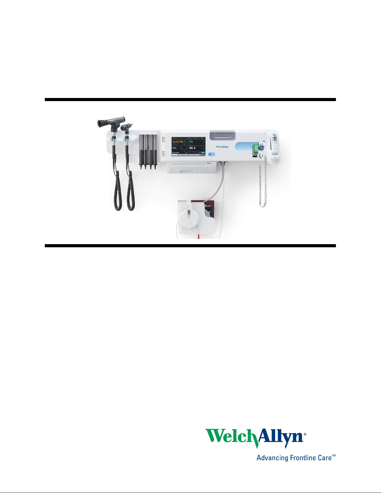
Welch Allyn Connex
Wall System
®
Integrated
Service manual
Software version 2.3X
Page 2

© 2018 Welch Allyn. All rights are reserved. To support the intended use of the product described in this
publication, the purchaser of the product is permitted to copy this publication, for internal distribution
only, from the media provided by Welch Allyn. No other use, reproduction, or distribution of this
publication, or any part of it, is permitted without written permission from Welch Allyn. Welch Allyn
assumes no responsibility for any injury to anyone, or for any illegal or improper use of the product, that
may result from failure to use this product in accordance with the instructions, cautions, warnings, or
statement of intended use published in this manual.
Welch Allyn, Connex, SureTemp, and SureBP are registered trademarks of Welch Allyn.
Oridion is a registered trademark of Oridion Medical 1987 Ltd. No implied license. Possession or
purchase of this device does not convey any express or implied license to use the device with
unauthorized CO2 sampling products which would, alone, or in combination with this device, fall within
the scope of one or more of the patents relating to this device and/or CO2 sampling products.
RRa is a trademark of; and SET, SpHb, rainbow, and Masimo are registered trademarks of Masimo
Corporation. Possession or purchase of a Masimo-equipped device does not convey any express or
implied license to use the device with unauthorized sensors or cables which would, alone or in
combination with this device, fall within the scope of one or more of the patents relating to this device.
Nellcor is a registered trademark of Covidien, PLC.
Braun and ThermoScan are registered trademarks of Braun GmbH.
Nonin is a registered trademark of Nonin Medical, Inc.
Bluetooth is a registered trademark of Bluetooth SIG.
Welch Allyn has provided Clinical Dynamics of CT, LLC, the calibration tables (CALTables) for use in its
AccuPulse and AccuSim NIBP Simulators. For more information,
Software in this product is Copyright 2018 Welch Allyn or its vendors. All rights are reserved. The
software is protected by United States of America copyright laws and international treaty provisions
applicable worldwide. Under such laws, the licensee is entitled to use the copy of the software
incorporated with this instrument as intended in the operation of the product in which it is embedded.
The software may not be copied, decompiled, reverse-engineered, disassembled, or otherwise reduced
to human-perceivable form. This is not a sale of the software or any copy of the software; all right, title,
and ownership of the software remain with Welch Allyn or its vendors.
This product may contain software known as “free” or “open source” software (FOSS). Welch Allyn
uses and supports the use of FOSS. We believe that FOSS makes our products more robust and secure,
and gives us and our customers greater flexibility. To learn more about FOSS that may be used in this
product, please visit our FOSS website at www.welchallyn.com/opensource. Where required, a copy of
FOSS source code is available on our FOSS website.
For patent information, please visit www.welchallyn.com/patents.
For information about any Welch Allyn product, contact your local Welch Allyn representative:
www.welchallyn.com/about/company/locations.htm.
DIR 80021577 Ver. A
Revision date: 2018-02
click this link.
Welch Allyn, Inc.
4341 State Street Road
Skaneateles Falls, NY 13153 USA
www.welchallyn.com
Regulatory Affairs Representative
Welch Allyn Limited
Navan Business Park
Dublin Road
Navan, County Meath
Republic of Ireland
Page 3

Contents
Symbols ................................................................................................... 1
Safety ....................................................................................................... 5
Overview .................................................................................................. 9
iii
Warnings and cautions ......................................................................................... 5
General safety considerations .............................................................................. 6
Electrostatic discharge (ESD) ............................................................................... 6
Purpose and scope .............................................................................................. 9
Technical support services ................................................................................. 10
Recommended service intervals ........................................................................ 14
The Welch Allyn Service Tool ............................................................................ 14
Battery performance .......................................................................................... 16
Controls, indicators, and connectors ................................................... 19
Service menu ......................................................................................... 23
Access the Service screens ............................................................................... 23
General tab ......................................................................................................... 23
Self-tests tab ...................................................................................................... 26
Logs tab ............................................................................................................. 26
Device tab .......................................................................................................... 27
Licensing tab ...................................................................................................... 27
Power-up sequence ............................................................................... 29
Troubleshooting .................................................................................... 31
Symptoms and solutions ................................................................................... 31
Technical alarm messages ................................................................................. 45
Disassembly and repair ........................................................................ 59
Required tools and equipment ........................................................................... 61
Disassembly overview ....................................................................................... 62
Section A ................................................................................................ 63
Power down the device ..................................................................................... 63
Exploded view, front exterior ............................................................................. 64
Exploded view, rear interior ............................................................................... 71
Section B .............................................................................................. 103
Power down the device ................................................................................... 103
Page 4

iv Contents Welch Allyn Connex® Integrated Wall System
Exploded view, front exterior ........................................................................... 105
Exploded view, rear interior ............................................................................. 112
Functional verification and calibration .............................................. 145
Functional verification tests ............................................................................. 145
Basic functional verification checks ................................................................. 148
Electrical safety testing ....................................................................... 163
Ground stud connector .................................................................................... 164
Options, upgrades, and licenses ........................................................ 165
Available options, upgrades, and licenses ....................................................... 166
Install options ................................................................................................... 168
Host firmware requirements ............................................................................ 170
Masimo parameter upgrades ........................................................................... 171
Configure options ............................................................................................. 171
Field replaceable units ........................................................................ 173
Front housing, handle module assembly, and modules - front exterior exploded
view ................................................................................................................. 173
Front housing, handle housing, and chassis - rear interior exploded view ....... 177
Miscellaneous parts ......................................................................................... 185
Licenses ........................................................................................................... 186
Partners in Care service and support agreements ........................................... 186
Service and repair training ................................................................................ 186
Appendices .......................................................................................... 187
Decontamination and cleaning requirements .................................................. 187
Configuration options ....................................................................................... 188
Factory defaults ............................................................................................... 190
Disassembly and repair reference ................................................................... 201
Connex Integrated Wall System interconnect diagram ................................... 209
Service record .................................................................................................. 211
Page 5
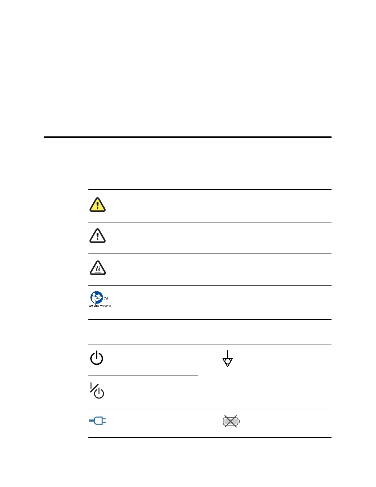
Symbols
For information on the origin of these symbols, see the Welch Allyn symbols glossary:
www.welchallyn.com/symbolsglossary.
Documentation symbols
WARNING The warning statements in this manual identify conditions or practices that could
lead to illness, injury, or death.
1
Power symbols
CAUTION The caution statements in this manual identify conditions or practices that could
result in damage to the equipment or other property, or loss of data. This definition applies to
both yellow and black and white symbols.
WARNING Hot surface. Do not touch.
Follow the operating instructions/directions for use (DFU) — mandatory action.
A copy of the DFU is available on this website.
A printed copy of the DFU can be ordered from Welch Allyn for delivery within 7 days.
Power on/Display power-saving
[recent models]
Power on/Display power-saving
[older models]
Equipotential terminal
(on the display) monitor is plugged
into Alternating Current power
Battery absent or faulty
Page 6
2 Symbols Welch Allyn Connex® Integrated Wall System
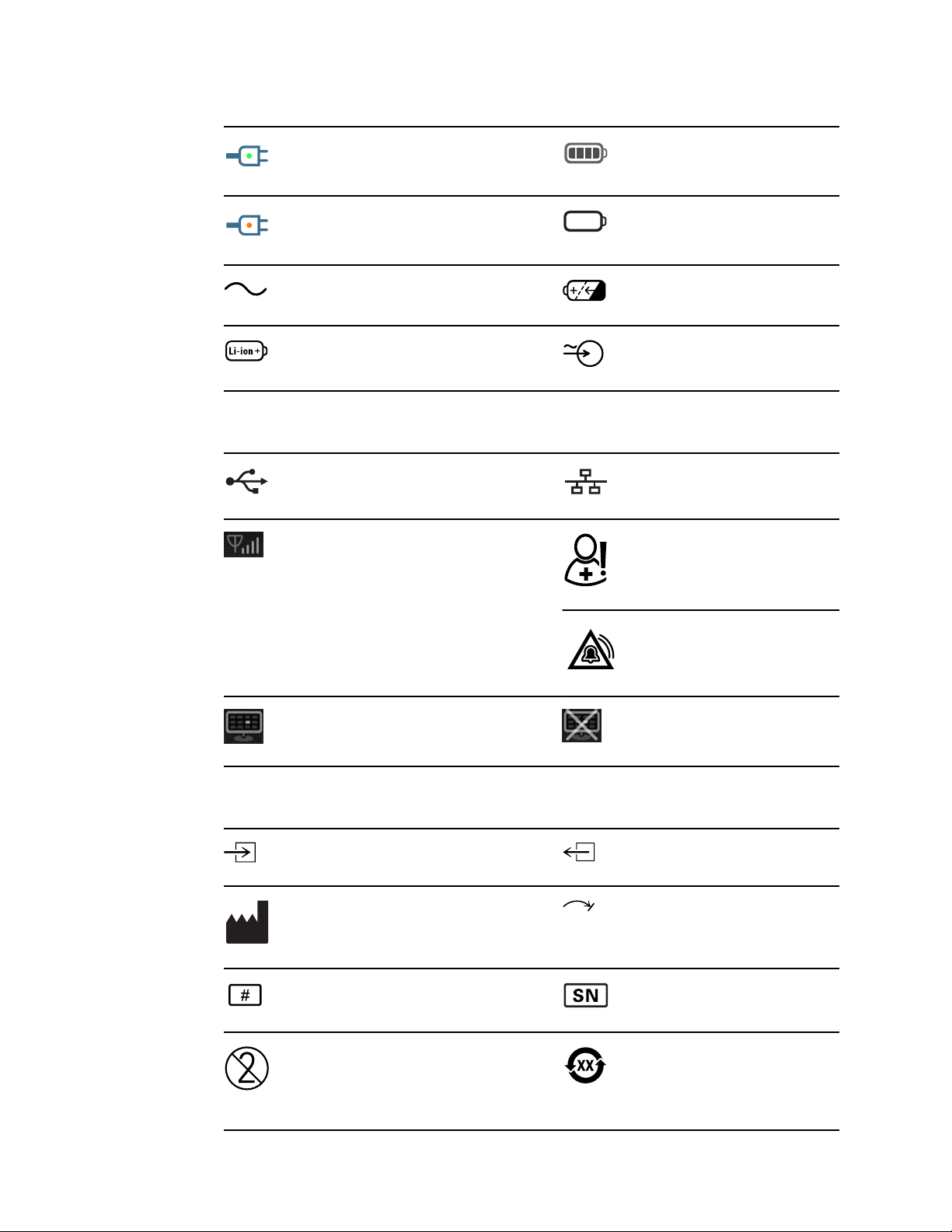
(on the monitor, green indicator)
Alternating Current power present,
battery fully charged
(on the monitor, amber indicator)
Alternating Current power present,
battery is charging
Alternating Current (AC) Rechargeable battery
Li-ion battery AC input power
Connectivity symbols
USB
Wireless signal strength
• Best (4 bars)
• Good (3 bars)
• Fair (2 bars)
• Weak (1 bar)
• No signal (no bars)
• No connection (blank)
Battery charge level
Battery cover
Ethernet RJ-45
Nurse call
[recent models]
Nurse call
[older models]
Connected to central station Disconnected from central station
Miscellaneous symbols
CO2 sampling input
Manufacturer Limited rotation/Turn completely to
Reorder number Serial number
Do not reuse China RoHS markings for control of
CO2 sampling output/exhaust
right
pollution caused by electronic
information products. XX indicates
Environmentally Friendly Use
Period in years.
Page 7
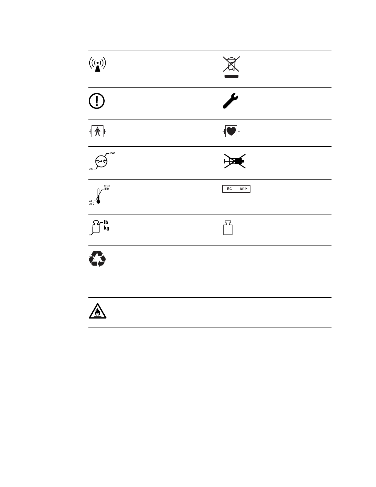
Service manual Symbols 3
Nonionizing electromagnetic
radiation
Restrictions for use of wireless
device in Europe. European
Community's Class 2 radio
equipment.
Defibrillation-proof Type BF applied
parts
Atmospheric pressure limitation Not for injection
Transport and storage temperature
range
Maximum safe working load limits
(specific values presented with
symbol)
Recycle the product separate from
other disposables
Call for maintenance
Defibrillation-proof Type CF applied
parts
Authorized Representative of the
European Community
Mass in kilograms (kg)
Recycle
Do not expose to open flame
IPX1
(Vital Signs
Monitor)
IPX0
(Integrated Wall
System)
Degree of protection provided by
the enclosure with respect to
harmful ingress of liquids
Page 8

4 Symbols Welch Allyn Connex® Integrated Wall System
Page 9
Safety
5
All users of the system must read and understand all safety information presented in this
manual before using or repairing the system.
United States federal law restricts this device to sale, distribution, or use by or on the
order of a licensed medical practitioner.
Warnings and cautions
WARNING Safety risk. Make frequent electrical and visual checks on
cables, sensors, and electrode wires. All cables, sensors, and electrode
wires must be inspected and properly maintained and in proper working
order to allow the equipment to function properly and to protect patients.
WARNING Safety risk. Place the system and accessories in locations
where they cannot harm the patient should they fall from a shelf or mount.
WARNING Fire and explosion hazard. Do not operate the system in the
presence of a flammable anesthetic mixture with air, oxygen, or nitrous
oxide; in oxygen-enriched environments; or in any other potentially
explosive environment.
WARNING Inaccurate measurement risk. Dust and particle ingress can
affect the accuracy of blood pressure measurements. Use the system in
clean environments to ensure measurement accuracy. If you notice dust or
lint build-up on the system’s vent openings, have the system inspected and
cleaned by a qualified service technician.
CAUTION Before disassembling the device or installing options,
disconnect the patient from the system, power down the device, and
disconnect the AC power and any attached accessories (for example, SpO2
sensors, blood pressure hoses and cuffs, and temperature probes) from
the device.
CAUTION To ensure that the system meets its performance
specifications, store and use the system in an environment that maintains
the specified temperature and humidity ranges.
CAUTION The system may not function properly if dropped or damaged.
Protect it from severe impact and shock. Do not use the system if you
notice any signs of damage.
Page 10
6 Safety Welch Allyn Connex® Integrated Wall System
CAUTION Do not connect more than one patient to a system or connect
more than one system to a patient.
CAUTION Do not operate the system in the presence of magnetic
resonance imaging (MRI) or hyperbaric chambers.
CAUTION Do not autoclave the system. Autoclave accessories only if the
manufacturer’s instructions clearly approve it.
General safety considerations
• If the system detects an unrecoverable problem, it displays an error message. For
more information see “Troubleshooting.”
• To ensure patient safety, use only accessories recommended or supplied by Welch
Allyn. (See the accessories list in the Welch Allyn Connex Integrated Wall System
Directions for use on the user documentation CD or http://www.welchallyn.com.
Always use accessories according to your facility’s standards and according to the
manufacturer’s recommendations and instructions. Always follow the
manufacturer’s directions for use.
• Welch Allyn recommends that only Welch Allyn service personnel or an authorized
repair center perform warranty service. Performing unauthorized service on a device
that is within warranty may void the warranty.
Electrostatic discharge (ESD)
CAUTION Electrostatic discharge (ESD) can damage or destroy electronic
components. Handle static-sensitive components only at static-safe
workstation.
CAUTION Assume that all electrical and electronic components of the
system are static-sensitive.
Electrostatic discharge is a sudden current flowing from a charged object to another
object or to ground. Electrostatic charges can accumulate on common items such as
foam drinking cups, cellophane tape, synthetic clothing, untreated foam packaging
material, and untreated plastic bags and work folders, to name only a few.
Electronic components and assemblies, if not properly protected against ESD, can be
permanently damaged or destroyed when near or in contact with electrostatically
charged objects. When you handle components or assemblies that are not in protective
bags and you are not sure whether they are static-sensitive, assume that they are staticsensitive and handle them accordingly.
Perform all service procedures in a static-protected environment. Always use
•
techniques and equipment designed to protect personnel and equipment from
electrostatic discharge.
Page 11

Service manual Safety 7
• Remove static-sensitive components and assemblies from their static-shielding bags
only at static-safe workstations—a properly grounded table and grounded floor mat—
and only when you are wearing a grounded wrist strap (with a resistor of at least 1
megohm in series) or other grounding device.
• Use only grounded tools when inserting, adjusting, or removing static-sensitive
components and assemblies.
• Remove or insert static-sensitive components and assemblies only with system
power turned off.
• Insert and seal static-sensitive components and assemblies into their original staticshielding bags before removing them from static-protected areas.
• Always test your ground strap, bench mat, conductive work surface, and ground
cord before removing components and assemblies from their protective bags and
before beginning any disassembly or assembly procedures.
Page 12

8 Safety Welch Allyn Connex® Integrated Wall System
Page 13

Overview
Purpose and scope
This manual is a reference for periodic preventive maintenance and corrective service
procedures for the Welch Allyn Connex Integrated Wall System, firmware version 2.3X.
It is intended for use only by trained and qualified service personnel.
9
Corrective service is supported to the level of field-replaceable units. These include
circuit-board assemblies and some subassemblies, case parts, and other parts.
Find instructions for functional testing and performance verification in the Welch Allyn
Service Tool help files.
This manual applies only to this device. For servicing of any other device, see the service
manual for the specific device.
Service work not described in this manual must be performed by qualified service
personnel at the factory or at an authorized Welch Allyn service center.
Related documents
When using this manual, refer to the following:
•
Welch Allyn Connex® Devices Directions for use, Software version 2.3X
(on the user documentation CD)
• Welch Allyn Service Tool
http://www.welchallyn.com/en/service-support/service-center/service-tool.html
• Welch Allyn Service Tool Installation and configuration guide
http://www.welchallyn.com/en/service-support/service-center/service-tool.html
• Welch Allyn Braun ThermoScan® PRO 6000 Ear Thermometer, Service manual
(80020325) click here to download the PDF
• Welch Allyn 9600 Plus Calibration Tester Directions for use
• Welch Allyn Radio Configuration guide click here to download the PDF
• Welch Allyn website: www.welchallyn.com
CAUTION No component-level repair of circuit boards and subassemblies
is supported. Use only the repair procedures described in this manual.
WARNING When performing a service procedure, follow the instructions
exactly as presented in this manual. Failure to do so could damage the
device, invalidate the product warranty, and cause serious personal injury.
Page 14

10
Overview Welch Allyn Connex® Integrated Wall System
Technical support services
Welch Allyn offers the following technical support services:
• Telephone support
• Loaner equipment
• Service agreements
• Service training
• Replacement service parts
• Product service
For information on any of these services, go to www.welchallyn.com.
Service loaners
For warranty or non-warranty repairs not covered under a support agreement, loaners are
available for a nominal charge, subject to availability. Payment is required prior to
shipment for all loaners not covered under a support agreement.
Welch Allyn Service Centers that provide repair service for this product can, on request,
loan a device for use while the device is being repaired. Loaned devices are provided
free of charge for products repaired while under a support agreement that includes a
free loaner provision.
Loaner equipment for the individual component modules is not available.
Service options
Partners in Care service agreements
While product warranties provide basic assurance of Welch Allyn hardware quality, they
may not include the full range of services and support you need. Welch Allyn offers
premium service and support through our Partners in Care program. Whether you
service your own devices and require a minimum of support or rely on us to service your
device, Welch Allyn provides a program that will meet your needs. A list of available
service and support agreements is presented in the "Field replaceable units" section of
this manual. For more information, visit our web site at www.welchallyn.com or call your
sales representative.
Warranty service
All repairs on products under warranty must be performed or approved by Welch Allyn.
Refer all warranty service to Welch Allyn Product Service or another authorized Welch
Allyn Service Center. Obtain a Return Material Authorization (RMA) number for all returns
to Welch Allyn Product Service.
Non-warranty service
Welch Allyn product service and authorized service centers support non-warranty repairs.
Contact any Welch Allyn regional service center for pricing and service options.
CAUTION Unauthorized repairs will void the product warranty.
Page 15

Service manual Overview 11
Welch Allyn offers modular repair parts for sale to support non-warranty service. This
service must be performed only by qualified end-user biomedical/clinical engineers using
this service manual.
Service training is available from Welch Allyn for biomedical/clinical engineers. Follow
this link for more information.
Repairs
A Welch Allyn Service Center must perform all repairs on products under warranty,
unless you have purchased a Welch Allyn Partners in Care Biomed agreement allowing
you to service the device while under warranty.
CAUTION Unauthorized repairs will void the product warranty.
Qualified service personnel or a Welch Allyn Service Center should repair products out of
warranty.
If you are advised to return a product to Welch Allyn for repair or routine maintenance,
schedule the repair with the service center nearest you.
Welch Allyn Technical Support
If you have a problem with the device that you cannot resolve, call the Welch Allyn
Technical Support Center nearest you for assistance. A representative will assist you in
troubleshooting the problem and will make every effort to solve the problem over the
phone, potentially avoiding an unnecessary return.
To expedite response to your issue, be prepared to provide details on how (steps
executed) and when (time and date) the problem occurred. Also, log and configuration
files captured on the device can assist with diagnosis and troubleshooting. You can
easily save these files from the device to a flash drive using controls on the Service tab.
See the "Service menu" section of this manual for details.
If your product requires warranty, extended warranty, or non-warranty repair service, a
Welch Allyn Technical Support representative will record all necessary information to
issue an RMA number. The support representative will provide you with the address of
the Welch Allyn Service Center to send your device to.
Technical support is available during local business hours.
Returning products
When returning a product to Welch Allyn for service, ensure that you have the following
information:
Product name, model number, and serial number. This information may be found on
•
the product and serial number labels on the bottom of the device.
Page 16
12 Overview Welch Allyn Connex® Integrated Wall System
• A complete return shipping address.
• A contact name and phone number.
• Any special shipping instructions.
• A purchase order number or credit card number if the product is not covered by a
warranty.
• A Partners in Care contract number if product is covered under a service agreement.
• A full description of the problem or service request.
Unless noted in the RMA, the device will be updated to the current software version. If
you prefer that the device not be updated, please state "Do not update software" in the
service request.
Note When requesting an upgrade, check the "Options, upgrades, and licenses"
section to determine if a software upgrade is required.
1. Obtain an RMA number:
• Visit us on the web at www.welchallyn.com/customer-self-service.htm, or
• Contact Welch Allyn to make a request.
Note Welch Allyn does not accept returned products without an
RMA.
2. Ship the device to Welch Allyn, observing these rules:
a. Remove from the package the battery, all hoses, connectors, cables, sensors,
power cords, and other ancillary products and equipment, except those items
that might be associated with the problem.
b. Follow shipping and handling requirements regarding Lithium-ion batteries to
comply with new IATA regulations.
Requirements for returning Lithium-ion batteries
• Remove the Lithium-ion battery from the device. You cannot ship these
devices with batteries installed.
• Follow packaging requirements (presented next in this section)
• Do not ship any battery that has been physically damaged or shows signs of
leakage.
• Do not ship any battery that has been recalled by the supplier or
manufacturer.
• Do not ship any waste batteries that should be recycled or discarded.
• Do not ship multiple batteries together.
• Use ground transportation only to ship Lithium-ion batteries.
Packaging requirements for Lithium-ion batteries and associated devices
Page 17

Service manual Overview 13
• Use packaging provided by Welch Allyn or the battery manufacturer to pack
the battery. Seal the battery in the anti-static bag and place it in the shipping
box. Return shipments without approved packing materials will not be
accepted.
Note If the original shipping carton or replacement battery
shipping box is unavailable, consult the manufacturer
website for information regarding shipping Lithiumion batteries:
http://www.iata.org/lithiumbatteries
• If returning both the battery and the device, pack the battery and the device
separately.
• If returning multiple batteries, pack and ship each battery individually. Do not
consolidate multiple batteries in a single package.
c. Clean the device.
Note To ensure safe receipt of your device by the service
center and to expedite processing and return of the
device to you, thoroughly clean all residues from the
device before you ship it to Welch Allyn. For
decontamination and cleaning requirements, see the
appendices.
If a returned device is found to be contaminated with
bodily fluids, it will be returned at the owner’s expense.
United States federal regulations prohibit the processing
of any device contaminated with blood-borne pathogens.
Welch Allyn thoroughly cleans all returned devices on
receipt, but any device that cannot be adequately
cleaned cannot be repaired.
d. Pack the device. Put the device, enclosed in a plastic bag with a packing list,
into the original shipping carton with the original packing materials or into
another appropriate shipping carton, and seal appropriately for shipping.
Remember that the device and any batteries must be packed and shipped
separately.
e. Write the Welch Allyn RMA number with the Welch Allyn address on the outside
of the shipping carton.
WARNING Safety risk. Do not ship any battery that has
been physically damaged or shows signs of leakage
unless you receive specific instructions which meet the
requirements for the shipment of Lithium batteries.
Dispose of damaged or leaking batteries in an
environmentally safe manner consistent with local
regulations.
WARNING Safety risk. Do not pack a defective battery
in checked or carry-on baggage if traveling by air.
Note In the United States, the applicable regulations can be
found in the Code of Federal Regulations (CFR). Refer to
49 CFR 173.185 for shipping lithium batteries by air or
ground. Use 49 CFR 172.102 sections 29, 188, 189, A54,
A55, A100, A101, A103, and A104 to find the special
provisions for shipping lithium batteries.
Page 18

14
Overview Welch Allyn Connex® Integrated Wall System
Recommended service intervals
To confirm that the device is functioning within the design specifications, perform
periodic service as indicated in the following table. Customers who have the Standard
unlicensed edition of the Welch Allyn Service Tool can perform the basic functional
verification and calibration procedures referenced in the table by following the
instructions in this manual. If you have the Gold licensed edition of the service tool, use
the tool to perform a complete functional verification and calibration of the device in lieu
of performing the basic tests.
Component Service interval Service procedure
NIBP module Annually Basic functional verification
SpO2 module Annually Basic functional verification
SpHb parameter Annually Basic functional verification
RRa parameter N/A N/A
SureTemp Plus Annually Basic functional verification
ECG N/A N/A
Braun ThermoScan PRO 6000 Annually Basic functional verification
Braun ThermoScan PRO 4000 Annually Basic functional verification
Battery 300 charge cycles Replace the battery
Use the service tool, Gold licensed edition, to perform a complete functional verification
and calibration of the device whenever any of the following conditions exist:
•
• The device has been dropped or otherwise damaged
• The device is malfunctioning
• The case has been opened
• An internal part has been replaced (battery excluded)
Note For instructions on using the Gold licensed edition, see the service tool
Maintenance
Based on the basic functional verification, the device does not meet specifications
help files.
For device maintenance information, see “Maintenance and service” in the wall
system's directions for use. Covered topics include the following:
Inspecting and cleaning the system and accessories
•
• Changing the battery
The Welch Allyn Service Tool
The Welch Allyn Service Tool is available in the following editions:
Page 19

Service manual
Overview 15
• Standard unlicensed: Download from http://www.welchallyn.com/service tool.
• Gold licensed: Required to perform complete functional verification and calibration.
This edition requires an additional license. For more information about acquiring this
license, contact Welch Allyn.
Note To qualify for the Gold license, you must attend the
Welch Allyn technical training course or complete online
training for the device.
Clinicians and technical service personnel can use the service tool to manage and
maintain supported Welch Allyn products. You can use the service tool to do the
following:
• Review device information. When connected to the device, the service tool lists
installed modules, installed firmware and hardware versions, warranty and repair
information, status, and usage history.
• Receive notifications when periodic maintenance is needed. The service tool can
help you manage and maintain your entire inventory of supported Welch Allyn
products. Through the remote service function, the service tool can connect to
Welch Allyn Customer Service. With this functionality you can automatically receive
firmware updates and feature upgrades for your supported products, including
software upgrades for the service tool.
• Install updates and upgrades. The service tool can read the firmware version for
each module and check for available updates or upgrades.
• Create a work list. The work list provides information about service actions—
referred to as work orders—that are waiting for you to perform on your maintained
devices. Work orders may include periodic calibrations, upgrades, or license
installations.
• Schedule periodic maintenance. You can use the service tool to set the service
interval for each maintained device.
• View and save logs. You can download and save log files from the device for
analysis to help diagnose and identify reported issues.
• Create user accounts. Administrators can create user accounts and set permission
levels to control access to the features, allowing one group to perform administrative
tasks and another to perform service tasks. Restricting access prevents the service
tool from being used to make unauthorized changes on a connected device.
• Perform functional verification and calibration. The service tool can check any
device requiring calibration and, if necessary, calibrate the device to match the
design specifications. This feature is not supported for all products and requires the
service tool, Gold licensed edition, for each supported product.
• Recover devices. In the rare case where a device can no longer boot because of
corrupted firmware, the service tool can connect the device to Welch Allyn Technical
Support to reinstall the firmware.
• Extensible. The service tool software accepts new plug-ins to support future Welch
Allyn products.
Some of these features are enabled for any user (Standard unlicensed edition). Others
require special user account privileges or a Welch Allyn service contract (Gold licensed
edition). If you require gold-level support for a Welch Allyn product, please contact
Welch Allyn technical support.
Page 20

16 Overview Welch Allyn Connex® Integrated Wall System
Battery performance
About the battery
Note The battery in the wall system provides backup power during a power
outage, not power for normal use. Except during cleaning and maintenance
activities, the wall system should remain connected to AC power at all
times.
The device uses a rechargeable Lithium-ion smart battery. Internal circuitry enables the
battery to report its condition to the device. The device displays the battery status via the
LED power indicator, icons on the screen, and status messages appearing in the Device
Status area of the display. Battery information may be collected using the service tool.
New batteries are shipped from the manufacturer with a 30 percent charge to extend
shelf life. When installing a new battery in the device, you must plug the device into AC
power to wake up the battery. If the AC power is not applied to the device, the new
battery will appear discharged.
The Device Status area displays a low-battery status message when 30 minutes of
power remain and again when 5 minutes remain.
Battery charging is provided by the device’s internal power supply.
For a complete list of battery specifications, see the device’s directions for use.
Best practices
The following practices help to extend the life of the battery and the device.
• Whenever possible, keep the monitor plugged in to charge the battery.
• Remove the battery when storing the device for an extended amount of time.
• Replace batteries that trigger a low battery status message when fully charged.
• Do not use damaged or leaking batteries.
• Store batteries with a 30 to 50 percent charge.
• Store batteries within the temperature range indicated for each period:
• Recycle batteries where ever possible. In the United States call 1-877-723-1297 for
• When recycling is not an option dispose of batteries in an environmentally safe
WARNING Safety risk. When handling and storing Lithium batteries: Avoid
mechanical or electrical abuse. Batteries may explode or cause burns, if
disassembled, crushed or exposed to fire or high temperatures. Do not
short or install with incorrect polarity.
○
For storage less than 30 days: Maintain temperature between –4 °F and 122 °F
(–20 °C and 50 °C).
○
For storage between 30 days and 90 days: Maintain temperature between –4 °F
and 104 °F (–20 °C and 40 °C).
○
For storage more than 90 days up to 2 years: Maintain temperature between –4
°F and 95 °F (–20 °C and 35 °C).
information about recycling your Lithium-ion battery or go to the Call2Recycle
website at http://www.call2recycle.org for additional information.
manner consistent with local regulations.
Page 21

Service manual Overview 17
Factors affecting battery operating time
The following settings and conditions affect the battery operating time:
• The display brightness setting
• The display power-saver setting
• The device power-down setting
• Frequency and duration of alarms and alerts
• Amount of motion artifact during NIBP measurements
• Radio searching for an access point
Page 22

18 Overview Welch Allyn Connex® Integrated Wall System
Page 23
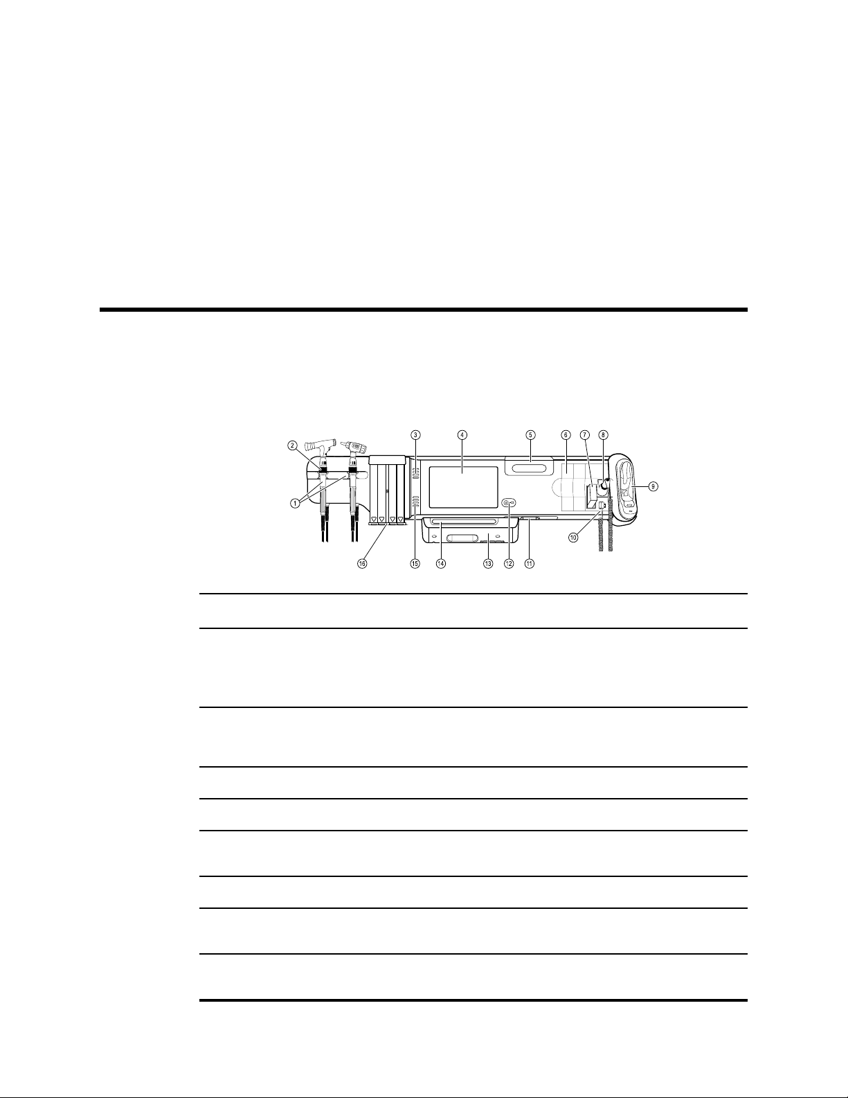
Controls, indicators, and connectors
Note Your model might not contain all of these features.
Front View
19
No. Feature Description
1 Physical assessment instruments - Handles
and handle cradles
2 Rheostat Light output adjustment located on each handle. Turn clockwise
3 Exhaust vents Provide openings for heat to escape and cool the device.
4 LCD screen 1024 x 600 color touchscreen provides a graphical user interface.
5 Storage compartment Provides covered storage for additional probe covers and other
6 Expansion slots Provide space to add modules.
7 SureTemp® Plus thermometer probe cover
storage area
8 SureTemp® Plus thermometer probe Supports temperature measurements from oral, axillary, and
Handles accept any 3.5V Welch Allyn instrument head.
Handle cradles support using one handle at a time. A handle
turns on automatically when you remove it from a cradle and
turns off when you return it.
to increase light output; turn counterclockwise to decrease light
output.
small accessories.
Provides storage for thermometer probe covers.
rectal sites.
Page 24
20 Controls, indicators, and connectors Welch Allyn Connex® Integrated Wall System
No. Feature Description
9 Braun ThermoScan® PRO thermometer and
dock
10 SureTemp® Plus thermometer connector Secures the probe connection to the wall system.
11 Blood pressure and pulse oximetry See front underside view for more detail.
12 Power switch and LED Power-on/Standby switch.
13 USB/Comms cover Houses light bar.
14 Light bar Provides a visual alarm with red and amber LEDs.
15 Speaker Provides tones. A piezo beeper inside the monitor provides
16 Specula dispenser Dispenses KleenSpec® disposable specula in pediatric (2.75 mm)
Support temperature measurements from the ear. Dock charges
the thermometer battery.
The LED indicates the charging status when connected to AC
power:
• Green: The battery is charged.
• Amber: The battery is charging.
Provides access to host USB connections for optional accessories
and some routing for cords and cables.
backup.
and adult (4.25 mm) sizes.
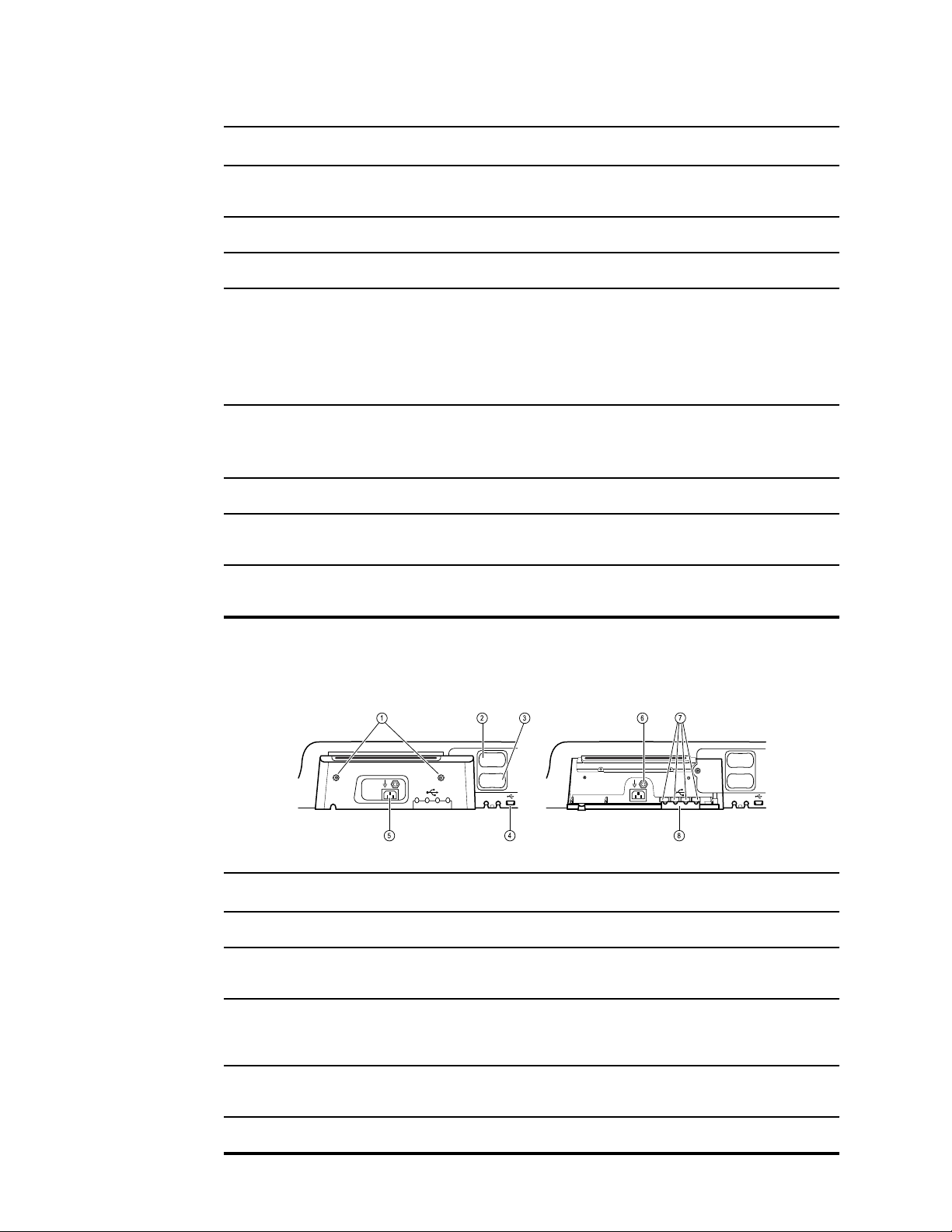
Front underside views
(Left: USB/Comms cover attached; Right: USB/Comms cover removed)
No.
Feature Description
1 Retention screws Attach USB/Comms cover.
2 Blood pressure Self-contained module for easy replacement. Supports dual-
3 Pulse oximetry Optional Nellcor (SpO2) or Masimo Rainbow SET (SpO2 or
4 USB-to-computer connector Provides a connection to an external computer for testing, data
lumen or single-lumen hoses.
combined SpO2/SpHb) in a self-contained module for easy
replacement.
transfer, and software upgrades.
5 Power connection Provides an external AC power connection.
Page 25

Service manual Controls, indicators, and connectors 21
No. Feature Description
6 Ground lug (equipotential terminal) Supports electrical safety testing; terminal for connecting a
potential equalization conductor.
7 USB connectors Provides access to host USB connections for optional
accessories.
8 USB cable retainer Reduces strain on USB cables and connectors; helps prevent
cables from disconnecting.
Back view
No. Feature Description
1 Recess for mounting bracket Secures the monitor when mounted on the wall.
2 Ethernet RJ-45 Provides a hardwired connection to the computer network.
3 Li-ion battery Provides backup power to wall system.
4 Nurse call Provides a connection to the hospital nurse call system.
Accessory bin
Feature Description
No.
1 Accessory bin Stores accessories and organizes cables.
2 SpO2 holder Provides location to wrap SpO2 cable and attach SpO2 finger clip.
Page 26
22 Controls, indicators, and connectors Welch Allyn Connex® Integrated Wall System
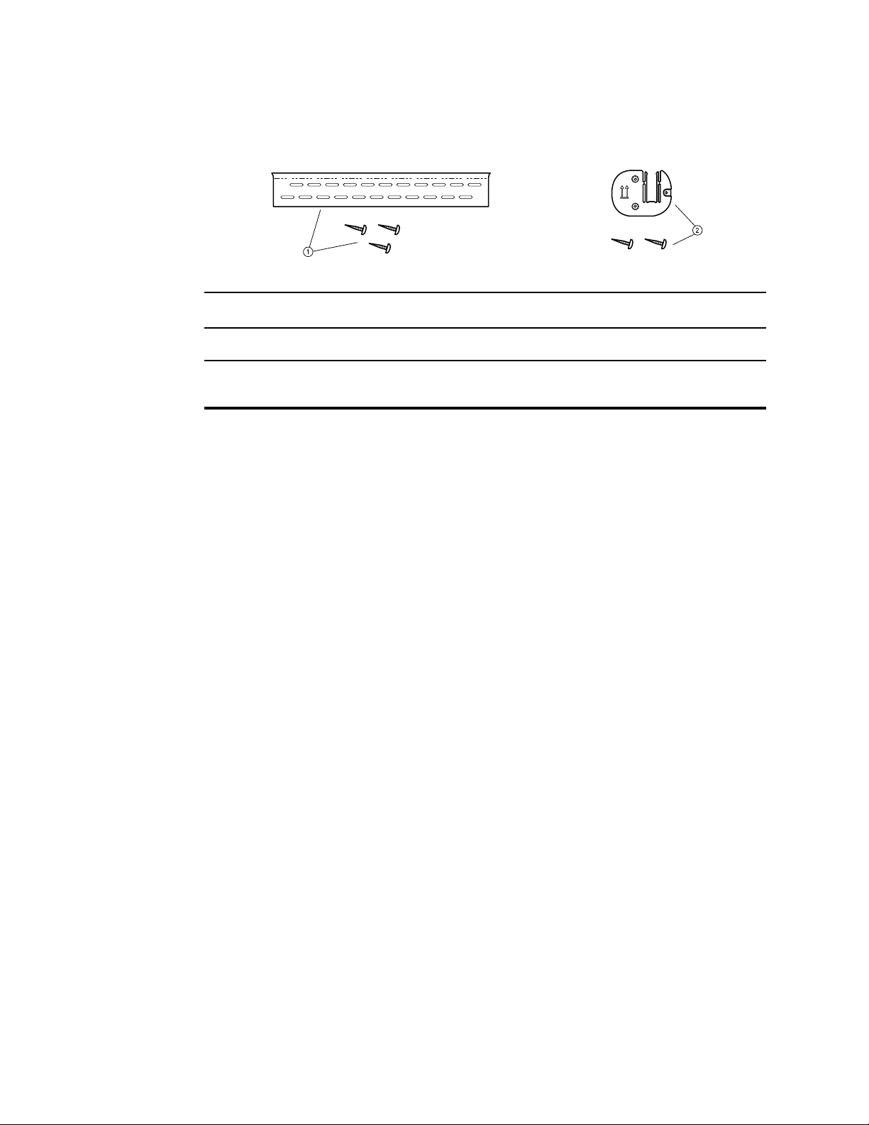
Mounting materials
No. Feature Description
1 Wall mounting rail bracket and hardware Secures the wall system to the wall.
2 Accessory bin mounting bracket and
hardware
Secure accessory bin to the wall and provide routing and strain
relief for power cord.
Page 27

Service menu
The Service tab is located inside Advanced settings. The Advanced tab provides
password-protected access to the monitor's Advanced settings (or Admin mode),
enabling nurse administrators, biomedical engineers, and/or service engineers to
configure specific features. The Advanced tab also presents read-only information about
the monitor.
Access the Service screens
23
Note You cannot access Advanced settings if sensors or physiological alarms are
active or if vital sign measurements are displayed.
1. Access the Advanced settings.
a. Touch the Settings tab.
b. Touch the Advanced tab.
c. Touch Enter password.
d. Enter your password and touch OK.
Note The default password is 6345, but your facility or
department might have a different password configured
on your device.
Note If you lose or forget your Advanced settings password,
contact Customer Service, who will guide you through
the password reset process.
The General tab appears.
2. Touch the Service tab.
The General tab appears.
3. Perform service tasks by navigating to the desired tabs and making selections.
4. When you finish your service tasks, touch Exit.
The Home tab appears.
General tab
Restore factory default settings
Note This process deletes the custom data file. All custom data will be lost.
Page 28

24
Service menu Welch Allyn Connex® Integrated Wall System
1. Go to the Service screens as described in “Access the Service screens.”
2. Touch the General tab.
3. Restore factory default settings:
• To restore radio settings to factory default values, touch Radio settings.
• To restore all current settings to factory default values, touch All settings.
A confirmation dialog appears.
4. Touch OK.
The factory default settings are restored.
If you selected Radio settings, the radio reboots, and the device remains powered
on.
If you selected All settings, the device reboots.
Save the device configuration or custom data to a drive
You can save the device configuration or custom data (custom modifiers and custom
scoring) to a USB flash drive. You can use the saved configuration to restore the device’s
configuration or to copy this configuration to use on other devices. You can use the
saved custom data to restore custom modifiers or custom scores or you can copy them
to another device.
Note Not all flash drives are supported.
Note When saving the device configuration, the location ID and asset tag
information is not included in the configuration file.
1. Connect a flash drive to the USB port.
2. Go to the Service screens as described in “Access the Service screens.”
3. Touch the General tab.
4. Touch Save to USB.
A confirmation dialog appears. You can save the device configuration or custom data
if either custom scores or custom modifiers are present.
5. Touch OK.
If the selected file or files already exist on the USB flash drive, a popup dialog
appears with the message Device configuration file already exists. Select OK to
continue with save and overwrite existing file or cancel.
6. Touch OK to save the data to the USB drive or touch Cancel to exit without saving.
A save confirmation message appears.
Note If the USB drive is incompatible, an information message Unable to save
configuration to USB message appears. Touch OK to continue.
Note The configuration file is saved as CONFIG.PMP. The custom data file is
saved as CUSTOMDATA.XML.
Load a device configuration or custom data
You can load a configuration from a USB flash drive to the device.
Page 29

Service manual Service menu 25
Note Not all flash drives are supported.
Note If your configuration includes radio parameters, make sure the radio is
enabled. The radio must be enabled before you can import radio
parameters.
Note If a device setting is not available in the configuration file, the setting
returns to the factory default. This might be the case when the
configuration file was saved from a device with a different firmware
version.
Note Configuration files cannot be cloned between devices with different host
software, except where the version change is minor.
1. Connect a flash drive to the USB port.
2. Go to the Service screens as described in “Access the Service screens.”
3. Touch the General tab.
4. Select Configure from USB.
A confirmation dialog appears.
5. Select Device configuration and/or Custom data XML.
A confirmation dialog appears to confirm overwriting the existing configuration.
6. Select OK to proceed, or Cancel to quit.
The configuration from the USB flash drive overwrites the configuration on the
device, and the device reboots.
Note If device configuration data is not present on the USB drive, that option will
Note If custom modifiers are not present on the USB drive, that option will be
Note If the configuration file is incompatible, an Unable to read configuration
Delete custom data
To delete custom data, you must restore the monitor to factory defaults. Restoring the
monitor to factory defaults also deletes all configuration settings.
To restore the custom configuration settings, save the configuration file to a drive and
reload the file after restoring factory defaults.
To determine if custom data is loaded on the device, complete these steps:
be disabled.
disabled.
from USB message appears. This might be the case if the configuration
file was cloned from a device with different software version.
Go to the Service screens as described in "Access the Service screens."
1.
2. Touch the Device tab.
A Custom file line displays the configuration name and the CRC in the Firmware
version column.
Page 30

26 Service menu Welch Allyn Connex® Integrated Wall System
Enter an asset tag
You can enter an alpha-numeric identifier in the data field to serve as an asset tag for
device identification.
1. Go to the Service screens as described in “Access the Service screens.”
2. Touch the General tab.
3. Touch and enter up to 20 characters.
4. Touch OK.
Note If the device language changes, the asset tag remains
unchanged.
Send device information to PartnerConnect
The device sends technical information, such as log files, to PartnerConnect periodically.
You can also manually send this information at any time by following this procedure.
1. Go to the Service screens as described in “Access the Service screens.”
2. Touch the General tab.
3. Touch Sync with server.
Self-tests tab
Calibrate the touchscreen
This tab calibrates the touchscreen, if needed.
1.
Go to the Service screens as described in “Access the Service screens.”
2. Touch the Self-tests tab.
3. Touch Start.
a. Touch the location indicated by the device. The device checks the current
calibration. If the location coordinates and touched location match, a Calibration
Confirmation dialog appears. Touch OK to finish.
b. If the locations do not match, a calibration failure dialog appears. Touch
Calibrate, and then touch the screen as indicated. When calibration is complete,
a Calibration Confirmation dialog appears. Touch OK to finish.
Logs tab
View an error or event log
1. Go to the Service screens as described in “Access the Service screens.”
2. Touch the Logs tab.
3. View a log report.
• To view an error log, select Error.
• To view an event log, select Event.
Page 31

Service manual Service menu 27
Save error and event logs to a USB flash drive
This feature is available in software versions 1.71.03 and later.
You can save a copy of the error and event logs to a USB flash drive.
Note Not all flash drives are supported.
1. Connect a flash drive to the USB port.
2. Go to the Service screens as described in “Access the Service screens.”
3. Touch the Logs tab.
4. Touch Save to USB.
A confirmation dialog appears.
5. Touch OK.
Copies of both log files are saved to the drive.
Device tab
View device and module information
1. Go to the Service screens as described in “Access the Service screens.”
2. Touch the Device tab.
Device and module information appears for you to view.
Licensing tab
View device licenses
Note After activating a new license, make sure to restart the device to complete
the activation process.
1. Go to the Service screens as described in “Access the Service screens.”
2. Touch the Licensing tab.
A list of available licenses appears. Checks indicate installed licenses.
Page 32

28 Service menu Welch Allyn Connex® Integrated Wall System
Page 33

Power-up sequence
The system performs a power-on self test (POST) each time the device is powered on.
During power up, the device performs a comprehensive self test of the software. If
software testing is successful, the device then tests internal hardware. If all tests are
successful, the system completes power up and the Home tab appears.
To perform the POST:
1. Disconnect any patient cables connected to the device.
2. Insert a fully charged battery into the device.
3. Upon each power up, confirm the following:
a. The light bar flashes amber.
b. The Welch Allyn startup screen appears.
c. A beep sounds, followed by one chime.
29
Note If no chimes sound, replace the speaker as specified in
“Replace the speaker.”
d. The product line logo appears at the bottom of the screen.
e. The Home tab appears.
WARNING Equipment failure risk. The device includes a fan that circulates
air through the device. If the fan does not run when you power up the
device, remove it from use and inform qualified service personnel
immediately. Do not use the device until the problem is corrected.
If the internal self-check is successful, the device shows its normal functions with all
values blank and the device is ready for operation. If the self-check fails, an error
message appears in the Device status area at the top of the screen. If a fault that could
adversely affect the product is detected, the device enters a safe mode and stops
monitoring patients. The device remains in safe mode until it is turned off or until it shuts
down automatically after a period of inactivity.
If a system error is detected, the device becomes inactive until you press or until the
device shuts down automatically. The device displays a system fault message that
contains a wrench icon( ) and a system fault code to aid service personnel and
engineers in diagnosing the problem.
While in safe mode, the red LED bar and the piezo buzzer cycle on and off.
Page 34

30 Power-up sequence Welch Allyn Connex® Integrated Wall System
Page 35

Troubleshooting
This section provides the following tables to help you troubleshoot the system.
• Symptoms and solutions: These tables list symptoms you might observe, list
possible causes, and suggest actions that might eliminate the problem.
• Technical alarm messages: These tables list messages generated by the system
software when a problem is detected. The tables explain possible causes and
suggest actions that can resolve the problem.
31
These tables can help you diagnose and fix a problem. They do not replace basic
troubleshooting skills. You must still trace the source of the problem to the board or
module level to decide the best course of action.
Welch Allyn does not support component-level repair to the board or module.
For available replacement parts, see “Field Replaceable Units.”
WARNING Do not perform troubleshooting on a system that is emitting
smoke or exhibits other signs of excessive overheating. Disconnect the
system from AC power and call Welch Allyn Technical Support
immediately.
CAUTION Replace parts, components, or accessories only with parts
supplied or approved by Welch Allyn. The use of any other parts can lead to
inferior performance and will void the product warranty.
Symptoms and solutions
Power
Symptom Possible cause Suggested action
The device does not power up A new battery was installed Connect AC power to wake up
the battery.
The AC power is disconnected Connect AC power.
The power cord is defective Replace the power cord.
The battery is discharged Charge the battery.
The power button is defective Replace the power button.
Page 36

32 Troubleshooting Welch Allyn Connex® Integrated Wall System
Symptom Possible cause Suggested action
An internal connection is faulty Check the power-flex cable
connection at J6 on the main
board.
Check the AC power harness
connections from the IEC
connector to the power supply.
Check the power harness from
the power supply J2 to J30 on
the main board.
Check the battery power harness
from J2 on the battery connector
board to J29 on the main board.
The power supply is defective Check the output voltage on the
power supply. The voltage should
be 15 V ± 0.45V DC. If it is not,
replace the power supply.
Hardware
The battery is defective Charge the battery for 5 hours. If
the battery icon on the display
still shows an empty battery
symbol, replace the battery.
The main board is defective Replace the main board.
The battery doesn’t charge or run
time is low
The battery is defective Charge the battery for 5 hours. If
the battery icon on the display
still shows an empty battery
symbol, replace the battery.
The battery connector board is defective Check the battery connector
board for an open short or broken
connector and replace if
necessary.
The battery has reached the end of its useful life Use the service tool to check
cycle count. If the cycle count
exceeds 300, replace the battery.
Mechanical Symptom Possible cause Suggested action
Noisy fan Dust build up Use canned air to blow dust out
of fan.
Fan is out of balance Replace fan.
Page 37

Service manual Troubleshooting 33
Mechanical Symptom Possible cause Suggested action
Cracks in housing Non-approved cleaning agents Replace plastic housing as
necessary.
Use only approved cleaning
agents.
Display
Symptom Possible cause Suggested action
The touchscreen does not respond Software error Reboot the device. Press and
hold the power button until the
device shuts down.
Note Any configuration settings
not saved as default will be lost.
Press the power button to restart.
The display is blank when the
power is on
The touchscreen is out of calibration In Advanced Settings, touch the
Service > Self-tests tabs, then
recalibrate the screen.
The touchscreen lock is activated To unlock the touchscreen, touch
at the bottom of the screen.
To disable the touchscreen lock,
touch the Settings > Device
tabs, then uncheck Allow
display lock timeout.
An internal connection is faulty Check the connection at J48 on
the main board with display flex
cable.
A display flex cable is broken Replace the touchscreen and
display assembly.
The main board has a faulty touchscreen
controller
Excessive force or prolonged rubbing in an area
of the touchscreen
The device is in Power-Saver mode Wake the display by touching the
Replace the main board.
Replace the touchscreen.
screen or the power button.
The device powered down after a period of
inactivity
An internal connection is faulty Check the display harness
Turn on the device by pressing
the power button. In Advanced
Settings, touch the General >
Display tabs, then set Device
power down to the desired
interval.
connections at the display and
Page 38

34 Troubleshooting Welch Allyn Connex® Integrated Wall System
Symptom Possible cause Suggested action
J19 on the main board. Replace
the cable if damaged.
A cable is damaged Replace the cable.
The display is dim The brightness setting is too low Increase the brightness setting.
Touch the Settings > Device
tabs, touch Defaults, then set
Display brightness to the
desired level.
The display has reached the end of its useful life Replace the display.
User interface
Symptom Possible cause Suggested action
Unable to access advanced
settings or enter the advanced
settings code
Desired profile does not appear in
the Profiles tab
Communication
Symptom Possible cause Suggested action
Cannot communicate through the
USB client connection
Patient monitoring is active or being simulated Discontinue patient monitoring or
stop the simulation.
The parameter alarm is on Dismiss the alarm.
Intervals are turned on Stop intervals.
The profile license is not installed In Advanced settings, touch the
Service > Licensing tabs.
Verify that the profile license box
is checked. If not, purchase the
license and install it using the
service tool.
The profile is not enabled In Advanced settings, touch the
Device tab, then check the
profile(s) you want to enable.
The battery charge is low Connect the device to AC power
and allow the battery to fully
charge.
The communications board does not receive
power
The USB client is defective Test the connection by
Check the voltage from J49 on
the main board for +5.0, ±0.5V
DC. Replace the main board if
necessary.
connecting a PC running the
service tool. Verify that the
service tool is configured
properly on the PC to
Page 39

Service manual Troubleshooting 35
Symptom Possible cause Suggested action
communicate with the device.
See the service tool help files.
Replace the power cable to the
communications board.
USB accessories do not
communicate with the monitor
The device does not communicate
via Ethernet with the computer
network
The accessory is defective Replace with a known good
accessory.
The communications board is not receiving power Check the voltage from J49 on
the main board for +5.0, ±0.5V
DC. Replace the main board if
necessary.
One or more USB host connections are defective Test the connection with a USB
thumb drive. If no power or
enumeration is present, such as
an LED on a thumb drive, replace
the communications board.
A USB connection from the communications
board to the main board is faulty
The device is not configured properly Check the settings with your
The communications board is not receiving power Check the voltage from J49 on
Verify that the USB cables are
connected correctly.
Replace the USB cables.
network administrator.
the main board for +5.0, ±0.5V
DC. Replace the main board if
necessary.
The radio does not connect to the
network
The Ethernet connection from the main board is
faulty
The network Ethernet switches are not set to the
correct speed to work with the device
The cable run to the switch is too long Use a shorter patch cable.
The device is out of range of the access point Check the network status
The device is not configured properly Check the settings with your
The antenna is defective Check the antenna cable and
Test the internal Ethernet cable.
Replace if necessary.
Verify that the shim is installed,
if required, on the Ethernet cable
connector at J11. See the
reassembly notes for the main
board.
Set the switches to 10 Mbps full
duplex.
screen’s RSSI value.
network administrator.
antenna connection. Replace the
cable and antenna if necessary.
Page 40

36 Troubleshooting Welch Allyn Connex® Integrated Wall System
Symptom Possible cause Suggested action
The communications board is not receiving power Check the voltage from J49 on
the main board for +5.0, ±0.5V
DC. Replace the main board if
necessary.
Alarms
Symptom Possible cause Suggested action
The light bar does not turn on No alarm was triggered Verify that the light bar flashes
when the system starts.
Verify that the alarm is triggered
by a visual indicator in the
message status area and an
audio alarm occurs.
There is a faulty connection Check the light-bar harness and
connections at the light bar and
J46 on the main board. Replace
the defective cable if necessary.
The light-bar board is defective Apply +3.3V to pin 1 of the
harness and ground to pin 2.
Verify that the amber LEDs
illuminate. Connect the ground to
pin 3. Verify that the red LEDs
illuminate. If one or both do not
illuminate, replace the LED light
bar.
The main board is defective Verify that there are +3.3V at pin
1 of J46 on the main board.
No audible alarm occurs No alarm was triggered Verify that the alarm is triggered
by a visual indicator in the
message status area and light
bar. Listen for audible sounds on
start up.
The alarm audio is set to Off
The alarm audio is set too low
Touch the Alarms > General
tabs, then select Alarm audio
on.
In Advanced settings, touch the
General > Alarms tabs, then
disable Allow user to turn off
general audio.
Touch the Alarms > General
tabs, then set Volume to the
desired level.
In Advanced settings, touch the
General > Alarms tabs, then
Page 41

Service manual Troubleshooting 37
Symptom Possible cause Suggested action
set Minimum alarm volume to
the desired level.
There is a faulty connection Check the speaker harness and
connections at the speaker and
J12 on the main board. Replace
the defective cable if needed.
The speaker is defective Replace the speaker.
The main board is defective Test speaker output using an
oscilloscope on J12.
NIBP
Symptom Possible cause Suggested action
SpO2
The NIBP frame on the display is
blank
The USB cable is defective Replace the USB cable.
The NIBP module is not connected Check the internal USB
connection.
The NIBP module is not functional Check the error logs for NIBP
errors. See the service tool help
files for details on specific errors
and suggested actions.
Check with Welch Allyn for
software updates.
If no NIBP error is logged, the main board might
be defective
Replace the main board if
necessary.
Symptom Possible cause Suggested action
The SpO2 frame on the display is
blank
The USB cable is defective Replace the USB cable.
The SpO2 module is not connected Check the internal USB
connection.
The SpO2 module is not functional Check the error logs for SpO2
errors. See the service tool help
files for details on specific errors
and suggested actions.
Check with Welch Allyn for
software updates.
If no SpO2 error is logged, the main board might
be defective
Replace the main board if
necessary.
Page 42

38 Troubleshooting Welch Allyn Connex® Integrated Wall System
SpHb
Symptom Possible cause Suggested action
ECG
The SpHb frame on the display is
blank
The SpHb frame is unavailable The selected profile does not support SpHb. Change the profile to Intervals
The UI license is not installed. Purchase a license and install the
license using the service tool.
The wrong sensor is connected. Use a sensor that supports the
SpHb parameter.
The sensor or cable expired. Replace the sensor or cable.
The sensor or cable is defective. Replace the sensor or cable.
The Masimo SpO2 module does not have the
SpHb parameter enabled.
Purchase the parameter and
install using the service tool.
Monitoring or Continuous
Monitoring.
Symptom Possible cause Suggested action
No LTA alarm associated with
patient injury or death
LTA license not installed Remove device from service,
contact Welch Allyn Technical
V-Tach, V- Fib, Asystole detection disabled
Invalid data
Support, and return to Welch
Allyn for service.
No LTA or ECG tile shows
Arrhythmia detection off
No ECG pane Module not connected Check ECG module LED.
ECG tile disabled Patient type set to Neonate Change patient type to Adult or
Alarms off in advanced settings Turn on alarms.
No license Install license.
ECG module unable to detect arrhythmias Contact Welch Allyn Technical
Support.
Replace the module if necessary.
Faulty patient cable Check cable.
Faulty module cable
CVSM software does not support ECG Update software.
Profile not set to Continuous Monitoring Set profile to Continuous
Monitoring.
Pediatric.
Page 43

Service manual Troubleshooting 39
Symptom Possible cause Suggested action
No waveform Start button not activated
ECG gain too high Reduce ECG gain.
Patient type set to Neonate Change patient type to Adult or
Noisy waveform 50 or 60 Hz filter disabled Enable filter.
Wrong mains filter value selected (50 Hz versus
60 Hz)
Poor lead placement See DFU for proper placement.
No pacer or ECG tile shows pacer
detection off
No alarming snapshot was autoprinted
Pacer detection Off
ECG module unable to detect pacer Contact Welch Allyn Technical
Automatic print on ECG alarm disabled In Advanced settings, touch the
Touch Start on ECG tile to begin
waveform streaming.
Pediatric.
Set the filter to the correct mains
frequency for your location.
Touch the Settings > Setup
tabs, then touch the ECG vertical
tab. Enable Patient has a
pacemaker.
Support.
Replace the module if necessary.
Parameters tab, then touch the
ECG vertical tab. Enable
Automatic print on ECG alarm.
See printer section for print
failures.
Device is not capable of printing Review ECG snapshots on the
device.
Snapshot button is disabled An alarming snapshot is in progress Wait for up to one minute for the
button to enable.
Less than one minute has elapsed between
snapshots
Module LED off Module is not receiving power Replace cable.
Module LED yellow Internal error Power cycle device or disconnect
and then reconnect cable.
Module LED steady green Module powered on Working as designed.
Module LED flashing green Sending data Working as designed.
Page 44

40 Troubleshooting Welch Allyn Connex® Integrated Wall System
Weight scale
Symptom Possible cause Suggested action
Weight does not appear in manual
parameter frame
Temperature
Symptom Possible cause Suggested action
The temperature frame on the
display is blank
The weight was not selected in Advanced
settings
The weight scale is not licensed Purchase a license and install the
The weight scale is not connected Check cables and connections.
The weight scale is not configured Consult the scale directions for
The USB cable is defective Replace the USB cable.
The temperature module is not connected Check the internal USB
In Advanced settings, touch the
Parameters tab, then select
Weight.
Note You can select only four
manual parameters.
license using the service tool.
Use the service tool to test
connectivity. Replace cables.
use.
connection.
The temperature module is not functional Check the error logs for
If no temperature error is logged, the main board
might be defective
Braun ThermoScan PRO 4000 thermometer
Symptom Possible cause Suggested action
The thermometer batteries don’t
charge
The dock LED is green, but the
battery is low or depleted
The rechargeable battery pack no longer takes a
charge
Primary AA batteries are installed in the
thermometer
Primary AA batteries are installed in the
thermometer
The dock is defective Replace the dock.
temperature errors. See the
service tool help files for details
on specific errors and suggested
actions.
Replace the main board if
necessary.
Replace the rechargeable battery
pack.
Replace the batteries with a
rechargeable battery pack.
Replace the batteries with a
rechargeable battery pack.
Page 45

Service manual Troubleshooting 41
Symptom Possible cause Suggested action
Thermometer readings do not
transfer to the device
The external USB cable is unplugged Check the external USB
The USB bus has stopped communicating with
the Braun dock. (The device displays wrench error
#00000014.)
Note For additional troubleshooting tips for the thermometer, see the
manufacturer’s product documentation.
Braun ThermoScan PRO 6000 thermometer
Symptom Possible cause Suggested action
Braun measurements are inaccurate Probe lens is displaced Examine lens for displacement. If you
Use inconsistent with DFU See DFU for proper operation. Perform
connection.
Reboot the host device.
observe a gap in the seam between the
bezel and the lens, replace the
thermometer.
the Braun functional verification test
using the service tool or the manual
test described in this manual. Replace
as necessary.
Ingress of cleaning solutions has
corroded the electronics
Temperature tile displays ++
Braun displays HI
Temperature tile displays - -
Braun displays LO
Braun displays “POS” error The infrared monitor cannot find a
Temperature taken is not within typical
human temperature range. HI will be
displayed when temperature is higher
than 108°F (42.2°C).
Temperature taken is not within typical
human temperature range. LO will be
displayed when temperature is lower
than 68°F (20°C).
temperature equilibrium and allows no
measurement.
Replace the thermometer. Review
cleaning procedures in the DFU.
Change probe cover to reset. Then,
make sure thermometer is properly
inserted and take a new temperature.
Change the probe cover to reset.
Restrict patient movement and ensure
that the positioning of the probe is
correct and remains stable while taking
new temperature.
Page 46

42 Troubleshooting Welch Allyn Connex® Integrated Wall System
Symptom Possible cause Suggested action
Braun displays “Err” error Ambient temperature is not within the
allowed operating range (50 – 104 °F
or 10 – 40 °C) or changing too rapidly.
Braun display is blank or displays all
icons
Braun displays Alert icon with “1” in
lower right corner
System error
Technique Compensation (PerfecTemp)
technology is not functioning or
disabled
Wait 20 seconds until thermometer
turns off automatically, then turn on
again. Ensure thermometer and patient
are in an environment for 30 minutes
where the temperature is between 50
°F and 104 °F or 10 °C and 40 °C.
Wait 20 seconds until the thermometer
turns off automatically, then turn on
again. If error persists, reset the
thermometer by removing the batteries
and putting them back in.
If error still persists, batteries are dead.
Insert new batteries.
If error still persists, contact local
Welch Allyn Service Center or
representative.
Open the temperature tab in Advanced
settings to configure PerfecTemp*.
Braun displays Alert icon with “U” in
lower right corner
C/F button is not functional Celsius only enabled Open the temperature tab in Advanced
Pulse timer button is not functional Pulse timer disabled Open the temperature tab in Advanced
Braun displays lock icon and is
unresponsive
Braun display is blank after performing
upgrade
*Host device Braun 6000 settings override configuration settings from Welch Allyn Service Tool.
Unadjusted Operating Mode is enabled
Security mode enabled and anti-theft
timer has expired
Software upgrade was interrupted Remove and replace the battery while
Open the temperature tab in Advanced
settings to configure Unadjusted
Operating Mode*.
settings to disable Celsius only
selection*.
settings to enable pulse timer*.
Return Braun thermometer to dock to
unlock. Security mode is set on
temperature tab in Advanced settings.
holding the C/F button or return to the
dock while holding the C/F button.
Retry upgrade.
Note For additional troubleshooting tips for the thermometer, see the
manufacturer’s product documentation.
Page 47

Service manual Troubleshooting 43
Manual parameters
Symptom Possible cause Suggested action
The manual parameter frame does
not appear on the Home tab
BMI is not displayed The BMI parameter is not selected Select the BMI parameter in the
Barcode reader
Symptom Possible cause Suggested action
The barcode reader powers on but
does not transfer data
No manual parameters are selected in Advanced
settings
Height or weight was changed Adjusting the height or weight
Weight scale not connected BMI is available only from a
No license is installed Purchase a license and install
The barcode reader is not programmed to use USB
Com Port Emulation mode
In Advanced settings, touch the
Parameters tab, then select the
desired manual parameters.
Note You can select only four
manual parameters.
advanced settings.
clears BMI.
weight scale with height.
the license using the service
tool.
Refer to the manufacturer's
documentation to program
the barcode reader to USB
COM Port Emulation mode.
Handles
The barcode reader is not supported For Honeywell model 4600g
barcode readers, verify that
the PID is set to 020A.
The barcode scanner did not enumerate properly Power cycle the Connex
device.
The patient ID or clinician ID do not
match
The barcode scanner is not programmed to properly
interpret the barcode
Program the barcode scanner
to turn on required symbology
and to also add or delete
characters to form correct ID.
Symptom Possible cause Suggested action
The lamp does not illuminate There is no lamp in the handle head Install a lamp in the handle head.
The lamp is burned out Install a new lamp.
The other handle is off the cradle Place the other handle in the cradle.
Page 48

44 Troubleshooting Welch Allyn Connex® Integrated Wall System
Symptom Possible cause Suggested action
The system is not powered up Power up the system.
The PCBA is defective Replace the PCBA.
The handle assembly is defective Replace the handle assembly.
The lamp is too dim The rheostat setting is too low Increase the rheostat setting.
The PCBA is defective Replace the PCBA.
The handle assembly is defective Replace the handle assembly.
The lamp is too bright The rheostat setting is too high Decrease the rheostat setting.
The PCBA is defective Replace the PCBA.
The handle assembly is defective Replace the handle assembly.
The lamp brightness does not adjust The PCBA is defective Replace the PCBA.
Errors
The handle assembly is defective Replace the handle assembly.
The handle becomes very hot to the
touch
The lamp has been on for an extended
period of time
Return the handle to the cradle.
Note The GS 777 Wall Transformer will accommodate instrument heads of the Welch Allyn approved
Halogen and LED type bulbs without any manual adjustment. For information about instrument heads,
follow the instructions provided in their directions for use.
Symptom Possible cause Suggested action
#000000001 An internal software error Power down and restart. If the
error persists, call Welch Allyn
#000000002 An unclassified hardware error
#000000003 Graphics RAM POST
#000000004 System RAM POST
#000000005 Watchdog POST
Technical Support for service.
#000000006 FLASH initiation failed
#000000007 A display system error
#000000008 A real-time clock error
#000000009 An audio system error
Page 49

Service manual Troubleshooting 45
Symptom Possible cause Suggested action
#000000010 An Ethernet system error
#000000011 The touchscreen controller failed
#000000012 Five or more SMBUS errors over a 1-minute period
occurred
#000000013 The communications module or main board failed
#000000014 Main board USB hub failure
#000000015 Software watchdog timer reset
Technical alarm messages
This section presents tables of technical alarm and information messages to help you
troubleshoot issues on the device. For information about physiological, dialog, or
informational messages, see the device’s directions for use.
When the device detects certain events, a message appears in the Device Status area at
the top of the screen. Message types include the following:
•
Information messages appear on a blue background.
• Very low-priority alarms appear on a cyan background.
• Low- or medium-priority alarms appear on an amber background.
• High-priority alarms appear on a red background.
Technical alarm messages are low priority or very low priority unless noted in the
Message column.
You can dismiss a message by touching the message on the screen, or, for some
messages, you can wait for the message to time out.
To use these tables, locate the message that appears on the device in the left column of
the table. The remainder of the row explains possible causes and suggests actions that
can resolve the issue.
If you cannot resolve the issue, use the service tool to read the error log files or use the
service tool to perform a functional test1 on the module reporting the message.
NIBP messages
Message Possible cause Suggested action
Alarm
NIBP air leak; check cuff and tubing
connections.
1
Requires the service tool, Gold licensed edition.
The NIBP module has an air leak Check the cuff, tubing, and
connections for leaks. If no leaks
are found, retake the
measurement. If the message
reappears, replace the NIBP
module.
Page 50

46 Troubleshooting Welch Allyn Connex® Integrated Wall System
Message Possible cause Suggested action
NIBP not functional. Call for
service.
Unable to determine NIBP; check
connections; limit patient
movement.
Unable to determine NIBP; check
connections and tubing for kinks.
Incorrect NIBP cuff size; check
patient type.
Internal errors or messaging errors occurred Check the error logs for NIBP
errors. See the service tool help
files for details on specific errors
and suggested actions.
Check with Welch Allyn for
software updates.
The ambient temperature is out of range Use the monitor in the specified
temperature range.
Pressure exceeded the maximum limit for this
patient mode
NIBP tubing on the outside of the device is kinked Check the connections and tubing
The NIBP module needs to be calibrated Perform NIBP calibration.
Tubing inside the NIBP module is kinked Replace the NIBP module.
A neonate cuff is in use with the monitor in adult
or pediatric mode
Check connections; limit patient
movement.
Clear the alarm and retry NIBP.
for kinks.
Clear the alarm and retry NIBP.
Check the patient type and cuff
size.
Clear the alarm and retry NIBP.
Inflation too quick; check NIBP cuff
and tubing connections.
Unable to determine NIBP; check
inflation settings.
Information
User cancelled NIBP reading. Blood pressure reading cancelled by user
Tube type does not match device
configuration.
(NIBP measurement is available)
NIBP inflation was too quick Check the connections and tubing
Target pressure was too low Check inflation settings and
Too many attempts Change the inflation setting.
The tube type connected to the monitor does not
match the NIBP configuration.
The single lumen switch on the NIBP connection
is stuck
for kinks.
Clear the alarm and retry NIBP.
change as necessary.
Clear the alarm and retry NIBP.
Change the inflation setting.
Touch OK to dismiss.
Touch NIBP Start button to
dismiss and restart the NIBP
reading.
Touch OK to dismiss.
Configure the NIBP advanced
settings to match the tube type,
patient type, and algorithm.
Use a small screw driver to press
the switch in and release until
the spring returns the switch to
the dual-lumen position.
Page 51

Service manual Troubleshooting 47
Message Possible cause Suggested action
Excessive patient movement. The NIBP reading was deemed not precise
SpO2 and SpHb messages
Message Possible cause Suggested action
Alarm
SpO2 not functional. Call for
service.
Touch OK to dismiss.
Limit patient movement and
restart the NIBP measurement.
The sensor is defective Replace the SpO2 sensor with a
known good sensor.
An internal error occurred Update the host software to the
current version.
Check the error logs for SpO2
errors. See the service tool help
files for details on specific errors
and suggested actions.
Check with Welch Allyn for
software updates.
Attach SpO2 sensor to monitor. The sensor was not detected Check the sensor connection.
Replace the sensor.
Replace the SpO2 sensor. The sensor is faulty Replace the sensor.
Searching for SpO2. (High-priority
alarm)
The sensor expired (applies only to SpO2 / SpHb
sensors)
No sensor is connected Connect the sensor.
The patient cable is faulty Replace the cable.
The SpO2 module is faulty Verify module functionality by
The SpO2 sensor is not attached to the patient’s
finger
Replace the sensor.
replacing the sensor with the
applicable SpO2 tester. If the
message persists after you have
installed the SpO2 tester, replace
the module.
Touch the alarm icon or the SpO2
frame to dismiss the alarm.
Set the SpO2 Alarm limits to Off.
Reattach the SpO2 sensor to the
patient's finger.
Low SpO2 signal quality. Check
sensor.
Poor sensor placement on the patient. Remove the sensor from the
patient and reapply.
Page 52

48 Troubleshooting Welch Allyn Connex® Integrated Wall System
Message Possible cause Suggested action
Low SpHb signal quality. Check
sensor.
Low perfusion. Check sensor.
SpO2 mode only. Check sensor or
cable.
SpO2 sensor expires in...
Note This message appears only
on devices configured with SpHb.
Replace the SpO2 cable. The cable is not functioning properly Replace the cable.
The patient cable or sensor is defective Replace the patient cable or
sensor.
The SpO2 module is faulty Verify module functionality by
replacing the sensor with the
applicable SpO2 tester. If the
message persists after you have
installed the SpO2 tester, replace
the module.
The sensor is operating as an SpO2-only sensor
because it failed to calibrate properly
The sensor will expire soon Replace the sensor.
The SpO2 module is faulty Verify module functionality by
Reattach the cable to the
monitor.
Remove the sensor from the
patient and reapply.
replacing the sensor with the
applicable SpO2 tester. If the
message persists after you have
installed the SpO2 tester, replace
the module.
Temperature messages (SureTemp)
Message Possible cause Suggested action
Alarm
Connect temperature probe. No probe is connected Connect a temperature probe and
The probe is faulty Replace the temperature probe.
The temperature module returned a connect
probe message
The SureTemp temperature module is faulty Verify module functionality by
Insert correct color-coded probe
well.
The probe well is missing Insert a temperature probe well.
The SureTemp temperature module is faulty Verify that the lever arm on the
retry.
Connect a temperature probe and
try again. If a probe is already
connected, replace the probe.
replacing the temperature probe
with the CAL-KEY assembly. If
the message persists after you
have installed the CAL-KEY
assembly, replace the module.
back of the probe well housing is
Page 53

Service manual Troubleshooting 49
Message Possible cause Suggested action
engaging switch SW1 on the
temperature PCBA. If the problem
persists, replace the module.
Replace temperature probe. The probe is faulty Replace the temperature probe.
The SureTemp temperature module is faulty Verify module functionality by
replacing the temperature probe
with the CAL-KEY assembly. If
the message persists after you
have installed the CAL-KEY
assembly, replace the module.
Retry temperature measurement.
Note This message often
accompanies other temperature
messages.
Temperature time limit exceeded.
Retry temperature measurement.
Information
Tissue contact lost. Lost tissue contact while attempting to acquire
A probe heater or data error occurred Retry the temperature
User settings require adjustment Adjust the user settings and
The ambient temperature is out of range Operate the monitor within the
The SureTemp temperature module is faulty Verify module functionality by
The direct mode timed out Return the temperature probe to
temperature reading or acquired reading was
performed with limited tissue contact
measurement. If the problem
persists, replace the probe.
retry.
specified temperature range.
Retry patient temperature
measurement.
replacing the temperature probe
with the CAL-KEY assembly. If
the message persists after you
have installed the CAL-KEY
assembly, replace the module.
the probe well and retry
measurement.
Touch OK to dismiss the
message. Start a new
temperature reading.
Temperature messages (Braun ThermoScan PRO)
Message Possible cause Suggested action
Alarm
Unable to detect temperature.
Retry measurement.
Measurement was not taken
Measurement recalled from memory
Loose or broken USB cable
Retry measurement.
Check USB connection and cable.
Replace as necessary.
Page 54

50 Troubleshooting Welch Allyn Connex® Integrated Wall System
Message Possible cause Suggested action
Thermometer might be docked
improperly.
Dead battery
Braun display is blank or battery icon shows one
bar
Braun displays “POS” error
Braun displays “Err” error
Ambient temperature is outside the allowed
operating range (50–104°F or 10–40°C) or
changes too rapidly
Thermometer is not properly docked Re-dock thermometer.
Thermometer has dirty contacts Clean dock and thermometer
Recharge or replace battery.
Change the probe cover to reset.
Restrict patient movement and
ensure that the positioning of the
probe is correct and remains
stable while taking new
temperature.
Wait 20 seconds until
thermometer turns off
automatically, then turn on again.
Ensure thermometer and patient
are in an environment for 30
minutes where the temperature
is between 50ºF and 104ºF or
10ºC and 40ºC.
contacts with 70 percent
isopropyl alcohol. See Cleaning
Instructions for Braun
ThermoScan PRO 6000.
Braun temperature not functional.
Call for service.
Communication timeout
BDD transfer took longer than expected
POST did not complete or failed within the
expected time period
POST failure
Braun display is all icons or blank
Unsupported parameter
Sensor data definition error (occurs when the
proxy is unable to set parameters to the sensor
using local DDS)
WACP serialization failure
Braun maximum battery voltage exceeded
Battery voltage is too high
Braun BDD compatibility
Braun BDD unexpected compatibility
Braun send message failure
Remove and replace battery to
reset, then return thermometer to
dock. If error persists, return for
service.
Page 55

Service manual Troubleshooting 51
Message Possible cause Suggested action
Braun bridge failure
Temperature is not functional. Call
for service.
ECG messages
Message Possible cause Suggested action
Alarm
Electrodes off: Device is configured for 5 leads, but
An internal error occurred
The USB cable is disconnected Check the USB cable.
The battery is depleted or missing Replace the batteries.
you are using 3 leads
Check the error logs for
temperature errors. See the
service tool help files for details
on specific errors and suggested
actions.
Check with Welch Allyn for
software updates.
Ensure that the device is
configured for the
appropriate number of
leads in Advanced
settings.
IEC electrodes (N, F, R, L, C) (N, F, R, L, C) disconnected Connect (N, F, R, L, C) lead.
AHA electrodes (RA, LA, LL, V) (RA, LA, LL, V) disconnected Connect (RA, LA, LL, V)
lead.
Electrode x off. One lead is disconnected Check the connections of
all leads.
ECG not functional. ECG module error, WACP error, Data
failure
ECG module has not transmitted ECG
data for the past 30 seconds
Check the USB cable and
connections.
Perform functional test. If
the test fails, contact
Customer Care and replace
the ECG module if
necessary.
Check the USB cable and
connections.
Perform functional test. If
the test fails, contact
Customer Care and replace
the ECG module if
necessary.
Page 56

52 Troubleshooting Welch Allyn Connex® Integrated Wall System
Message Possible cause Suggested action
ECG module disconnected Check the ECG module
connection to Connex
device.
Unexpected alarm compatibility bits Restart the Connex device
and the ECG module; if the
error persists, contact
Customer Care.
Perform functional test. If
the test fails, contact
Customer Care and replace
the ECG module if
necessary.
Cannot analyze ECG. Module unable to analyze the ECG
signal for V-Tach, V-Fib, and/or asystole
Cannot measure ECG. ECG module has been unable to detect
and ECG waveform for the past 30
seconds
Check electrodes and
leads, and replace as
needed.
Check the patient cable
connection to the ECG
module.
Perform functional test. If
the test fails, contact
Customer Care and replace
the ECG module if
necessary.
Check electrodes and
leads, and replace as
needed.
Check the patient cable
connection to the ECG
module.
Perform functional test. If
the test fails, contact
Customer Care and replace
the ECG module if
necessary.
Searching for respiration. ECG unable to measure patient
respirations
Check electrodes and
leads, and replace as
needed.
Check the patient cable
connection to the ECG
module.
Perform functional test. If
the test fails, contact
Customer Care and replace
the ECG module if
necessary.
Page 57

Service manual Troubleshooting 53
Message Possible cause Suggested action
Respiration alarm limits changed. Respiration physiological alarm limits
Weight scale messages
Message Possible cause Suggested action
You are not using Lead II to view
respiration
Attempting to acquire ECG/Impedance
respiration
were modified because the respiration
source changed
Ensure that you are
viewing Lead II for
respiration.
Check electrodes and
leads, and replace as
needed.
Check the patient cable
connection to the ECG
module.
Perform functional test. If
the test fails, contact
Customer Care and replace
the ECG module if
necessary.
Reset alarm limits.
Weight scale not functional. Call
for service.
The weight scale is not operating properly Check the scale.
Communications module messages
Message Possible cause Suggested action
Communications module did not
power on properly. Power down
the device. (High-priority alarm)
The communications board is not connected
properly to the main board
The communications board malfunctioned Replace the communications
Use the service tool to check
connectivity with adapter.
Replace cables.
Replace adapter.
Check the USB connection at J4.
Check the Power connection at
J50. Check the voltage from J49
on the main board for +5.0V
±0.5V DC. Replace the main
board if necessary.
board.
Page 58

54 Troubleshooting Welch Allyn Connex® Integrated Wall System
Radio messages
Message Possible cause Suggested action
Alarm
Radio not functional. Call for
service.
Radio error. Power down and
restart.
Unable to establish network
communications. Radio out of
network range.
A hardware failure occurred Replace the radio.
The radio has the wrong software Update the radio software.
The monitor and the radio failed to establish
communication with each other
The radio is no longer communicating with the
access point
Power down and restart the
monitor.
If the problem persists, check the
following:
• The USB and power
connections from the main
board to the
communications board.
• The connection from the
radio board to the
communications board.
• Monitor and radio software
compatibility.
Replace the radio if necessary.
Verify that the monitor is within
the radio coverage area. Verify
that the radio is correctly
configured to the network. If this
message appears intermittently,
check the RSSI value.
Unable to establish network
communications. Call for service.
Radio Software upgrade failed. The connection with the host was broken Re-establish the connection and
Information
Radio software upgrade in
progress. Do not shut down.
Radio card rebooting; please wait. The radio is restarting as part of the software
Unable to get an IP address from the DHCP server Verify that a DHCP sever is
available on the network. The
monitor requires an IP address
from a DHCP server.
try again.
The radio was not provisioned correctly Reset radio to factory defaults
and try again.
Hardware error Replace the radio.
Radio software is being written to the radio Do not interrupt the upgrade until
complete.
Do not interrupt the upgrade until
upgrade
complete.
Page 59

Service manual Troubleshooting 55
Ethernet messages
Message Possible cause Suggested action
Alarm
Network not found; check network
cable connection.
USB messages
Message Possible cause Suggested action
Alarm
External device not recognized. An unrecognized external device is connected Reconfigure the external device.
USB Communication failure. Call
for service
A network cable is unplugged Check the network cable
connection.
A network connection is broken elsewhere Check network wiring.
Replace the external device.
Disconnect the unsupported
device.
An internal or external device is connected but
failed enumeration
Power down and restart.
Check the external device.
Check external and internal USB
connections.
Information
External device not licensed for
use.
Unable to save configuration to
USB.
Unable to read configuration from
USB.
USB accessory disconnected. The USB cable between an external device and
A device requiring a license has been connected
to the USB connection
There was a problem writing the configuration
file to the USB flash drive
There was a problem reading the configuration
file to the USB flash drive
the monitor is disconnected
Obtain an authorization code
from Welch Allyn to activate the
license.
Use a Welch Allyn approved
flash drive.
Verify that the flash drive is not
locked.
Verify that there is space
available on the flash drive.
Restart and try again.
Confirm that the USB cable is
connected to the device and the
monitor.
Page 60

56 Troubleshooting Welch Allyn Connex® Integrated Wall System
System messages
Message Possible cause Suggested action
Alarm
Set date and time. The date or time is not set Set the date and time.
The date or time is not set properly Reset the date or time.
Incompatible Welch Allyn device. A known USB device enumerates, but fails The device may be faulty. Test a
known good device.
Unexpected restart occurred. Call
for service.
Information
Device shutdown is not available
at this time.
A system error caused the monitor to restart Check Event and Error logs. Run
The device cannot perform an immediate
shutdown
Battery power manager messages
Message Possible cause Suggested action
Alarm
Low battery 5 minutes or less
remaining. (High-priority alarm)
Battery power is extremely low Plug the monitor into AC power.
the service tool verification test.
Touch OK to dismiss message.
If any process is active, wait for
it to complete before attempting
shutdown.
If the device is unresponsive,
hold down the power button until
device shuts down.
Note Any configuration changes
not saved as default are lost.
If not plugged in, the monitor
automatically powers off.
Battery is absent or faulty. There is no battery in the monitor Insert a battery.
Battery is absent or faulty. Call for
service.
Low battery 30 minutes or less
remaining.
Information
Device is operating in battery
mode.
The battery is faulty Replace the battery.
The battery power is low Touch the alarm icon to dismiss
or plug the monitor to AC power.
The AC power cord has been disconnected Touch the alarm icon to dismiss
or plug the monitor to AC power.
Page 61

Service manual Troubleshooting 57
Configuration Manager messages
Message Possible cause Suggested action
Alarm
Unable to load configuration; using
factory defaults.
Functional error. Call for service. A critical configuration load error occurred Replace the main board.
Information
No connection for send. The monitor is not configured to the network
A configuration load error occurred Restore factory defaults. If the
Patient data management messages
Message Possible cause Suggested action
Alarm
error persists, replace the main
board.
In Advanced settings, touch the
Data Management > Clinical
Data tabs, then disable
Automatically send on
manual save if you only want to
store readings on the device.
If your want to send readings,
then configure the device to the
network.
Maximum number of patient
records saved. Oldest record
overwritten.
Information
No data saved. No patient data is available Take or enter vital signs before
Patient ID required to save data. The configuration requires a patient ID to save
Clinician ID required to save data. The configuration requires a clinician ID to save
Patient ID required to send data. The configuration requires a patient ID to send
Patient list is full. Delete some
patients to add more.
The maximum number of patient records has
been saved on the device
data
data
data
The maximum number of patients was exceeded Delete a patient from the list to
Go to the Review tab and delete
old records to prevent the alarm
from appearing when new
records are saved.
saving.
In Advanced settings, touch the
Data management > Patient
tabs, then disable Require
patient ID to save readings.
In Advanced settings, touch the
Data management > Clinician
tabs, then disable Require
clinician ID to save readings.
Add a patient ID.
add a new patient.
Page 62

58 Troubleshooting Welch Allyn Connex® Integrated Wall System
Message Possible cause Suggested action
Stop intervals to select new
patient.
No connection for send. No connectivity is available to support sending
Unable to identify clinician. The clinician ID or password is incorrect Confirm the clinician ID and
Unable to retrieve list. The device is unable to retrieve a patient list
Network messages
Message Possible cause Suggested action
Lost connectivity with host. The central station or other host
The device is set to take interval readings Stop intervals before changing
the patient.
Check the network connection.
data manually or automatically sending data on
manual save
from the network
application has stopped running or
is not operating properly
Check the Radio Configuration
settings.
password (if applicable), and
retry.
Check the network connection.
Check the Radio Configuration
settings.
Verify that the server is available.
Confirm that the host application
is running properly.
Page 63

Disassembly and repair
This chapter is divided into two major subsections, defined in the table below.
Section A Section B
59
(IEC 60601 3rd-edition compliant)
Devices meeting these criteria:
• Manufactured before 12/2017*
• MCE hardware version P3 or earlier
(see the right pane on the Settings tab)
• Built before serial number* 100023374817
* See "Device serial number and model label" in the Appendix for serial number format and meaning.
Examine your device to determine which subsection you should follow to complete
disassembly and repair procedures.
This overview includes exploded views of the front externior and rear interior that include
callouts referencing the parts. These exploded views apply to both Section A and Section
B, though certain parts are labeled as specific to one section or set of devices and not
the other. In the instructions, numbers in parentheses refer to callouts in the exploded
drawings. Except where otherwise noted, the reassembly procedure is the reverse of
the disassembly procedure.
Each part’s disassembly instructions may include one or both of the following
subsections:
•
Reassembly notes: This contains information specific to reassembly not addressed
in the disassembly instructions, especially when reassembly is not a simple reverse
of disassembly.
• When replacing the component: This contains information specific to installing a
new option or replacement part.
Devices meeting these criteria:
• Manufactured after 12/2017*
• MCE hardware version P5 or later
(see the right pane on the Settings tab)
• Built after serial number* 100023374817
WARNING Electrical shock hazard. Disconnect AC power before opening
the device. Disconnect and remove the battery before opening the main
chassis. Failure to do this can cause serious personal injury and damage to
the device.
WARNING Risk of fire, explosion and burns. Do not short-circuit, crush,
incinerate, or disassemble the battery pack.
Page 64

60
Disassembly and repair Welch Allyn Connex® Integrated Wall System
WARNING Safety risk. Do not attempt to service the device when the
device is connected to a patient.
CAUTION Before disassembling the device or installing options,
disconnect the patient from the monitor, power down the device,
disconnect the AC power cord and any attached accessories (SpO2
sensors, blood pressure hoses and cuffs, temperature probes, ECG
modules, Braun docks, and barcode scanners) from the device.
CAUTION Remove the probe well in the temperature module prior to
disassembly.
CAUTION Perform all repair procedures at a static-protected station.
CAUTION When the device case is opened, regard all parts as extremely
fragile. Execute all procedure steps with care and precision.
CAUTION Observe screw torque specifications, especially with screws
that secure directly into plastic standoffs.
CAUTION To avoid mismatching screws and holes, keep the screws for
each piece with that piece as you remove modules and circuit assemblies.
It is possible to mistakenly install machine screws in locations intended for
plastite screws. Plastite screws in this device have a Torx-pan head.
CAUTION After performing any of these procedures and prior to returning
the device to service, you must use the service tool, Gold licensed edition,
to complete the full suite of functional tests to ensure that all systems are
operating within the design specifications. For more information about
these tests and the service tool, see “Functional verification and
calibration.”
If you do not have the service tool, contact Welch Allyn Technical Support.
For information about screws or connectors used in the device, see the Appendix.
Page 65

Service manual Disassembly and repair 61
Required tools and equipment
• #1 Phillips bit
• #2 Phillips bit
• #10 Torx bit
• Torque driver calibrated for 6.0 in-lb ±1.0 in-lb
• Torque driver calibrated for 7.5 in-lb ±0.5 in-lb
• Slotted screwdriver
• Tweezers
• Needle-nose pliers
• Spudger
• Tie-wrap tool calibrated for torque specification 5 INT
• Tie-wrap cutter
• Soft lens wipes
• Scissors or other cutting device
• Canned air
• Adhesive tape
• Pro Gaff tape
For information about screws and connectors used in the device, see the Appendix.
Page 66

62 Disassembly and repair Welch Allyn Connex® Integrated Wall System
Disassembly overview
The following chart provides an overview of the complete disassembly of the device.
Most disassembly activities require that you complete a subset of the steps detailed
here. The flow chart indicates the steps that must be completed in sequence to remove
a particular component. Because a different sequence of preliminary steps might be
required to remove certain components, you should use this flow chart as a reference at
the start of every disassembly and component replacement procedure. A list of
preliminary steps presented at the start of each disassembly topic provides the
prerequisites for that disassembly task. (Some tasks in the flowchart are optional,
depending on the scope of disassembly.)
Page 67

Section A
This section applies to devices manufactured before 12/2017, serial numbers before
100023374817, and MCE hardware version P3 or earlier.
Note If your device does not meet these criteria, see Section B for the correct
If the MCE hardware version is P2 or P3, DO NOT replace any components with service
kits with the "3rd Ed" suffix. IEC 3rd Edition service kits are not compatible with
hardware versions P2 and P3.
63
disassembly and repair instructions.
Power down the device
You can power down the device as follows: 1) on devices with 2.X software, briefly
press the power button on the housing and then following the onscreen prompts, or 2)
on all devices, use onscreen controls alone.
Option 1. After the device is powered up, briefly press of the power button to open an
onscreen dialog with the following options:
•
Power down. Device behavior varies based on the active profile, whether or not
patient trend data is stored, and whether or not patient context is established. While
servicing the device, you need not be concerned about these details. They only
matter to clinicians who are monitoring patients and storing patient data.
• Sleep. The Sleep button clears the display and puts the device into Display power-
saving mode.
• Cancel. The Cancel button dismisses the dialog.
Touch Power down and complete the power-down procedure.
Option 2. To use onscreen controls alone to power down the device, follow these steps:
1.
Touch the Settings tab.
2. Touch the Device tab.
3. Touch Power down.
Note The next three sections address disassembly and repair steps you can
complete without removing the device from the wall or removing the
battery. All steps presented after “Remove the system from the wall and
remove the battery” require powering down as well as removing the
device from the wall and removing the battery.
Page 68

64 Section A Welch Allyn Connex® Integrated Wall System
Exploded view, front exterior
No. Item No. Item
4 Side housing 23 Power button
5 SureTemp module 30 Blue insert
8 CIWS handle module assembly 41 NIBP module
9 Braun housing 42 SpO2 module
10 Platform module, blank 43 Braun dock
16 Module cover 44 Strain relief, comms, PW
17 Communications cover housing 45 Ear speculum dispenser, small
18 Cubby door 50 Screw, M3 x 0.5, Pan Phillips
20 Side mounting bracket/Module retaining plate
Replace modules in the bottom housing
1. Power down the system and disconnect the AC power cord.
2. Disconnect the NIBP hose and the SpO2 cable if present.
3. Remove the communications cover housing.
Loosen the two captive screws using a #2 Phillips screwdriver to remove the
communications cover.
Page 69

Service manual Section A 65
4. Remove the module cover.
Loosen the captive screw using a #2 Phillips screwdriver to remove the module
cover.
Note The modules fit tightly in the housing but can become loose
5. Remove the module you want to replace.
Slide the module out of the housing by inserting a finger in the slot at each end of
the module and gently pull the module away from the housing until you completely
remove it.
6. Disconnect the USB cable from the rear of the module.
Reassembly notes
• When aligning the module with the housing, the USB connection is on the left.
• The NIBP module must always be in the front-most slot.
over time. Support the modules to prevent them from falling
out as you remove the module cover.
Page 70

66 Section A Welch Allyn Connex® Integrated Wall System
Replace modules in the main housing
Note Check how the end cap or Braun thermometer housing are attached to the
device. If bushings with captive screws attach the end cap or Braun
thermometer housing to the side of the main housing as shown in step 1,
proceed with the instructions as presented. If you don't see bushings with
captive screws on the end cap or the Braun thermometer housing, then
these parts are attached to the back of the chassis, not the right side. To
remove these parts and access any front-facing modules, first remove the
device from the wall. (See "Remove the system from the wall and remove
the battery.")
1. Power down the system and disconnect the AC power cord.
2. Loosen the two captive #2 Phillips screws that hold the end cap or the Braun
thermometer housing in place.
3. Remove the end cap or thermometer housing by sliding the piece away from the
wall and then to the right.
4. Disconnect the USB cable from the Braun dock, which you can access from the rear
of the Braun housing.
5. Locate and remove the module retaining plate by removing the four #2 Phillips
screws.
Page 71

Service manual Section A 67
6. If SureTemp is installed, remove the module and the probe cover storage together,
sliding them out the open end, and disconnect the USB cable.
7. Slide any blank face plates or modules to be removed toward the open end.
Note When removing any connected modules, disconnect the
USB cables before you remove the module.
Note If you are replacing a Braun 4000 thermometer with a Braun
6000 thermometer, you must also replace the dock.
Remove the Braun dock from the housing
1. Hold the Braun housing with your right hand and the dock with your left hand as
shown. With your right-hand fingers inside the housing, gently press the housing
toward you and away from the dock. At the same time, gently push the dock away
from you until the dock unsnaps from the housing.
2. When the dock is completely loose, remove it from the housing.
Reassembly notes
• When aligning the module with the housing, the USB connection is on the bottom.
• The temperature module must always take up the last two spots closest to the end.
• The blank cover's beveled edge must be on the right when facing the device for
proper alignment.
Page 72

68 Section A Welch Allyn Connex® Integrated Wall System
• When replacing the Braun dock, insert the bottom of the dock into the housing, align
the molded ridges in the top of the dock with the slots in the top of the housing, and
snap the dock into the housing.
Remove the system from the wall and remove the battery
1. Power down the system and disconnect the AC power cord.
2. Disconnect any detachable sensors and cables:
• Blood pressure cuffs and hoses
• Temperature probes and cables
• Braun thermometer
• SpO2 sensors and cables
• 3.5V instrument heads
3. Remove any items in the storage area and any other loose items before attempting
to remove the system from the wall.
4. Close the storage area door and seal it with a piece of adhesive tape to prevent the
door from opening.
5. Remove the speculum holder by lifting it up and away from the handle housing.
6. Remove the AC power cord.
7. Remove the communications connection cover.
Loosen the two captive screws, using a #2 Phillips screwdriver, until the cover is
free from the housing.
Page 73

Service manual Section A 69
8. Remove the wall anchor screws using a #2 Phillips screwdriver.
9. Hold the bottom and top of the system and push it up to remove the system from
the wall mounting bracket.
10. Place the wall system on a table or flat work surface so that the back of the wall
system faces up. Ensure that the display is protected from pressure or getting
scratched.
11. Locate the battery, indicated by
12. Remove the battery.
Remove the light-bar board
Complete the following preliminary steps:
•
Power down the system and disconnect the AC power cord.
• Remove the system from the wall and remove the battery.
1. Remove the two torx screws from the light-bar cover.
2. Remove the light bar and cover.
Page 74

70 Section A Welch Allyn Connex® Integrated Wall System
3. Remove the light bar from the light-bar cover.
4. Disconnect the light-bar harness from the light-bar board.
5. Remove the light-bar board from the light bar by sliding the board out from the
connector end.
Reassembly notes
• Insert the light-bar board by placing the end without the connector into the open end
of the light bar.
• Slide the light-bar board into the light bar until the connector end is flush with the
end of the light bar.
• Feed the light-bar harness wires through the slot so they do not get pinched during
reassembly.
Page 75

Service manual Section A 71
Exploded view, rear interior
No. Item No. Item
1a LCD with touchscreen 31 LCD bezel
2a Main board 32 LCD frame
3 Main housing 33 Chassis
6 Platform fan assembly 34 Cable, USB client
7 Platform speaker assembly 35 Handle assembly
11 Module well assembly 36 PCBA: Platform 767 controller, pattern E
12 Light bar 37 Handle, cradle, and opticals assembly, cool blue
13 Power panel 38 Housing, front handle
14 Battery housing 39 Housing, rear handle
15 Module track 40 IR connector and wire assembly
19 Light-bar cover 50 Screw, M4 x 10, Pan head with nyloc (Large
Phillips screw)
21 Light-bar board 51 Screw, M3 x 0.5, Pan Phillips (Small Phillips screw)
Page 76

72 Section A Welch Allyn Connex® Integrated Wall System
No. Item No. Item
22 Battery connector 52 Screw, Plastite #4-20 x .500 Pan head (Torx screw)
23 Power button and flex cable 53 CCH44-S10 P-clamp, 0.437
30 Blue insert
Remove the handle module assembly
Complete the following preliminary steps:
• Power down the system and disconnect the AC power cord.
• Remove the system from the wall and remove the battery.
1. Cut and remove the cable tie that holds the USB ferrite in place.
2. Disconnect the USB cable.
3. Remove the ferrite from the USB cable by pulling apart the two clips and lifting up.
4. Remove the four large Phillips screws while supporting the end of the handle
module assembly.
5. Lift the handle module assembly up and away from the main assembly while guiding
the USB cable through the slotted opening.
Page 77

Service manual Section A 73
Remove the handles
Complete the following preliminary steps:
• Power down the system and disconnect the AC power cord.
• Remove the system from the wall and remove the battery.
• Remove the handle module assembly.
1. Remove the six large Phillips screws on the back of the assembly, then lift and
remove the rear handle housing.
2. Disconnect the handle connector wires from the 767 Controller PCBA.
3. Lift and remove the handle cables from the front handle housing.
Reassembly note
When reconnecting the handle connection wires to the handle PCBA, the connecting
wires must be facing up and away from the PCBA.
Remove the 767 controller PCBA
Complete the following preliminary steps:
Power down the system and disconnect the AC power cord.
•
• Remove the system from the wall and remove the battery.
Page 78

74 Section A Welch Allyn Connex® Integrated Wall System
• Remove the handle module assembly.
• Remove the handles.
1. Disconnect the two IR wire connectors from the handle PCBA.
2. Remove the three Torx screws.
3. Lift and remove the PCBA.
Reassembly note
When reconnecting the IR wire connectors to the handle PCBA, the connecting wires
must be facing down and toward the cradle assemblies.
Remove the handle cradle and optical assemblies
Complete the following preliminary steps:
•
Power down the system and disconnect the AC power cord.
• Remove the system from the wall and remove the battery.
• Remove the handle module assembly.
• Remove the handles.
• Remove the 767 Controller PCBA.
1. On the rear of the assembly, disconnect both IR wires from the optical sensors.
2. Push in the snap tabs and remove the cradle assembly by pushing outward.
Page 79

Service manual Section A 75
Reassembly notes
• For ease of assembly, connect the IR wire assemblies to the optical sensors before
attaching the handle cradle to the handle assembly housing.
• Attach the connector with the black and white wires to the optical detector
(indicated by the letter "B" molded into the cradle plastic). Attach the connector with
the red and white wires to the optical emitter. The wires should face inward once
the handle cradle is assembled.
• Snap the handle cradle assembly into the front housing. Make sure that the cradle
assembly tab and the beveled edge are at the top of the housing.
Open the chassis
Complete the following preliminary steps:
Power down the system and disconnect the AC power cord.
•
• Remove the system from the wall and remove the battery.
• Remove the handle module assembly.
• If the Braun option is accessible from the side, remove it as described in "Replace
modules from the main housing."
1. Complete one of the two substeps below based on your system details.
Page 80

76 Section A Welch Allyn Connex® Integrated Wall System
• For systems built before July 15, 2011 with the Braun thermometer option
or end cap mounted to the rear chassis:
a. Remove the 6 screws as shown.
b. Disconnect the USB cable from the rear of the Braun housing.
c. Remove the two large Phillips screws that hold the end cap or the
thermometer housing in place, and remove the end cap or thermometer
housing.
• For systems built after July 15, 2011 with the Braun thermometer option or
end cap mounted to the side mounting bracket:
a. Remove the Braun module if present as described in "Remove modules from
the main housing."
b. Remove the 8 screws as shown.
2. Remove the two Torx screws securing the client USB connector to the housing, and
then disconnect and remove the cable.
CAUTION Multiple wire connections are still connected
between the front housing and the chassis. These must be
disconnected before it is safe to completely separate the
two pieces.
3. Carefully lift the top of the chassis away from the front housing while leaving slack in
all cable connections.
From the communications board, disconnect the following in the order presented:
Page 81

Service manual Section A 77
Number Item
1 Small 4-pin connector
2 Mini USB cable
3 USB cable
4 Ethernet cable
4. Disconnect the power supply cable from the power supply.
5. Separate the chassis from the front housing.
Page 82

78 Section A Welch Allyn Connex® Integrated Wall System
Exploded view, chassis
No. Item No. Item
33 Chassis 56 Radio board
51 Screw, M3 x 0.5, Pan Phillips (Small Phillips screw) 57 Antenna board
52 Screw, Plastite #4-20 x .500 Pan head (Torx screw) 58 Ground lug
54a Power supply, 60W 59 IEC connector
55 Communications board
Remove the power supply
Complete the following preliminary steps:
•
Power down the system and disconnect the AC power cord.
• Remove the system from the wall and remove the battery.
• Remove the handle module assembly.
• Open the chassis.
1. Disconnect the green ground cable and the AC power harness from the power
supply.
Page 83

Service manual Section A 79
2. Remove the four torx screws.
3. Remove the power supply.
Reassembly note
When reinstalling the power supply, orient the board so that the end of the board with
the AC-to-power-supply (J1) connection is closest to the IEC connector.
Remove the ground lug, AC power harness assembly, and IEC connector
Note Do not disconnect the AC power harness from the IEC connector unless
you are replacing it. Once your disconnect the AC power harness, you
cannot reuse it.
Complete the following preliminary steps:
•
Power down the system and disconnect the AC power cord.
• Remove the system from the wall and remove the battery.
• Remove the handle module assembly.
• Open the chassis.
1. Disconnect the AC power harness and ground from the power supply.
2. To remove the ground lug:
Page 84

80 Section A Welch Allyn Connex® Integrated Wall System
a. Remove the 10mm hex nut and slide out the star lock washer and the ground
wire (power supply) ring terminal.
b. Remove the next 10 mm hex nut and slide out the star lock washer, the ground
wire (mains) ring terminal, and the flat washer.
c. Remove the bare ground lug by pulling it out from the outside of the chassis.
3. To remove the IEC connector:
a. Disconnect the three power wires: blue neutral (N), green ground (G), and brown
line (L).
Note You must now replace the AC power harness. It cannot
be reused.
b. Push in on the three plastic release tabs to release the IEC connector.
Remove the communications board
Complete the following preliminary steps:
•
Power down the system and disconnect the AC power cord.
• Remove the system from the wall and remove the battery.
• Remove the handle module assembly.
• Open the chassis.
1. Disconnect the mini-USB connection on the outside of the chassis.
Page 85

Service manual Section A 81
2. Turn over the chassis to access the communications board.
3. Remove the four Torx screws.
4. Lift the communications board from the chassis.
5. For systems with the radio option, remove the tape securing the antenna cable, and
rotate the communications board counter-clockwise to clear the chassis. Make sure
not to pull on the antenna cable. Turn the board over and place it inside the chassis.
6. If replacing the communications board, remove the radio board as described in
"Remove the radio board and antenna."
Remove the radio board and antenna
Note Do not remove the radio antenna from the chassis unless you are replacing
the radio and antenna or the chassis.
Complete the following preliminary steps:
•
Power down the system and disconnect the AC power cord.
• Remove the system from the wall and remove the battery.
• Remove the handle module assembly.
• Open the chassis.
• Remove the power supply.
• Remove the ground lug, AC power harness, and IEC connector.
• Remove the communications board.
1. Remove the radio board:
a. Turn the communications board over to access the radio board, taking care to
avoid straining the antenna cable.
b. Remove the four small Phillips (machine) screws securing the radio board to the
communications board.
Page 86

82 Section A Welch Allyn Connex® Integrated Wall System
c. Hold the communications board with one hand while grasping the radio board at
the opposite end from the antenna connection and pull the radio board away
from the communications board.
2. Remove the antenna and antenna cable.
a. Remove the Pro Gaff tape securing the antenna cable to the housing.
b. Carefully disconnect the antenna cable by lifting up on the wire neck just before
c. Use a soft tool such as a spudger to separate the adhesive from the inside of the
Reassembly notes
If the antenna is removed:
•
Clean the chassis and mounting surface with 70 percent isopropyl alcohol.
• Peel the backing off the double-stick tape and affix it to the chassis antenna plate.
• Mount the antenna to the antenna plate. Make sure the PG terminal on the antenna
board is facing outwards.
Antenna cable connection:
Attach the antenna cable to terminal G on the radio board. Attach the other end of
•
the cable to the antenna on terminal PG.
the connection point.
chassis of the antenna plate.
Page 87

Service manual Section A 83
• Once the antenna, radio, and communications board are mounted and secure,
secure the antenna cable to the housing with Pro Gaff tape.
Replace the chassis
Complete the following preliminary steps:
• Power down the system and disconnect the AC power cord.
• Remove the system from the wall and remove the battery.
• Remove the handle module assembly.
• Open the chassis.
• Remove the power supply.
• Remove the communications board.
• For systems with the radio option, remove the radio board and antenna.
Remove the USB client cable from the outer side of the chassis by removing the two
Torx screws.
Disconnect or remove the light bar
Complete the following preliminary steps:
•
Power down the system and disconnect the AC power cord.
• Remove the system from the wall and remove the battery.
• Remove the handle module assembly.
• Open the chassis.
1. Remove the two Torx screws from the light-bar cover.
Page 88

84 Section A Welch Allyn Connex® Integrated Wall System
2. Remove the light bar and cover.
3. Remove the light bar from the light-bar cover.
4. Disconnect the light-bar harness from the light-bar board.
5. If replacing the light-bar board, remove the light-bar board from the light bar by
sliding the board out from the connector end.
Reassembly notes
• Insert the light-bar board by placing the end without the connector into the open end
of the light bar.
• Slide the light-bar board into the light bar until the connector end is flush with the
end of the light bar.
• Feed the light-bar harness wires through the slot so they do not get pinched during
reassembly.
Disconnect or remove the fan
Complete the following preliminary steps:
Power down the system and disconnect the AC power cord.
•
• Remove the system from the wall and remove the battery.
• Remove the handle module assembly.
Page 89

Service manual Section A 85
• Open the chassis.
1. Disconnect the power cable from the fan harness connector.
2. Press the flanges on the sides of the fan harness connector and separate the fan
connector from the power panel.
3. If you are removing the fan, slide the fan up and remove.
Reassembly note
Install the fan with the label facing the power panel.
Disconnect or remove the power panel
Complete the following preliminary steps:
Power down the system and disconnect the AC power cord.
•
• Remove the system from the wall and remove the battery.
• Remove the handle module assembly.
• Open the chassis.
Page 90

86 Section A Welch Allyn Connex® Integrated Wall System
• Remove the fan.
1. If you haven't done so already, disconnect the power cable from the fan harness
connector.
2. Disconnect the two harness connectors from the battery board.
3. Disconnect the speaker connector wire.
4. Remove the two Torx screws that attach the power panel to the front housing and
slide the power panel out of the housing.
Page 91

Service manual Section A 87
5. Pull the module handle assembly USB cable through the access hole in the power
panel.
Reassembly notes
• Pull the module handle assembly USB cable through the access hole in power panel
before securing the power panel to the housing.
• When installing the power panel in the housing, do not obstruct the channel or allow
the battery board or battery housing to push the LCD flex sideways.
• Reconnect the speaker, battery board, and fan harnesses.
Remove the speaker
Complete the following preliminary steps:
• Power down the system and disconnect the AC power cord.
• Remove the system from the wall and remove the battery.
• Remove the handle module assembly.
• Open the chassis.
• Remove the power panel.
1. Carefully pry the speaker and adhesive away from the power panel.
2. Remove any remaining gasket material and clean the surface with 70 percent
isopropyl alcohol.
3. Remove the paper on the speaker to expose the adhesive on the gasket.
4. Apply pressure to the outer radius of the speaker assembly to assure good adhesion
with the power panel.
Replace the battery board
Complete the following preliminary steps:
•
Power down the system and disconnect the AC power cord.
• Remove the system from the wall and remove the battery.
• Remove the handle module assembly.
• Open the chassis.
• Remove the power panel.
1. Remove the battery compartment from the power panel by pushing in on the four
plastic tabs.
2. Remove the two Torx screws from the battery compartment and remove the battery
board.
Page 92

88 Section A Welch Allyn Connex® Integrated Wall System
3. Secure the new battery board to the battery compartment with two Torx screws.
Disconnect or remove the power wire harness and main wire harness
Note If removing the main board or LCD, it is not necessary to cut wire ties
attaching the harness to the housing unless you are replacing the harness
or the housing.
Note When replacing the main harness, you must disconnect the light-bar board
from the main harness.
Complete the following preliminary steps:
•
Power down the system and disconnect the AC power cord.
• Remove the system from the wall and remove the battery.
• Remove the handle module assembly.
• Open the chassis.
1. Disconnect the USB connections from the main board in positions 1 through 8 and
10 and 11. Remove the USB cables from the cable separator to clear the work area.
2. Disconnect the connectors as follows:
• To disconnect the power harness, disconnect the connectors at J29 and J30.
• To disconnect the main harness, disconnect the connectors at J34, J12, J49,
J46, and J45.
Page 93

Service manual
3. If you are replacing the power harness, carefully cut the two wire ties and remove
the harness.
4. If you are replacing the main harness, disconnect the main harness from the power
panel, carefully cut the two wire ties, and remove the harness.
Reassembly notes
When replacing the harness standoff:
• Orient the harness standoff so that the main harness communications power, light
bar, and fan wires run parallel to the top of the main board.
• Mount the harness standoff to the frame, aligning the edge of the standoff with the
edge of the main board directly beneath the screw and securing the upper left-hand
corner of the frame.
Section A 89
When replacing the main harness:
•
Align the shrink-wrapped sections and their wire tie anchors with the light-bar wires
on the left.
• Feed the light-bar wires through the rectangular opening in the bottom of the
housing to the right of the module well.
• Attach the harness to the main housing using the wire tie anchors closest to the
display or front of the housing.
When replacing the power harness:
Page 94

90 Section A Welch Allyn Connex® Integrated Wall System
• Align the shrink-wrapped sections with the wire tie anchors.
• Align the end with the wire tie closest to the end on the left to connext with the
main board.
• Attach to the main housing using the wire tie anchors closes to the back of the
housing.
• Route the connections from the main harness to the main board (communications
power, light bar, fan) over the last USB cable, under the remaining USB cables, and
through the harness standoff. Twist to lock the harness in the standoff.
Remove the main board
Complete the following preliminary steps:
•
Power down the system and disconnect the AC power cord.
• Remove the system from the wall and remove the battery.
• Remove the handle module assembly.
• Open the chassis.
• Disconnect the power wire harness and the main harness.
1. Disconnect the following on the main board:
a. The power button flex cable at J6.
b. The LCD harness at J19.
c. The LCD flex cable at J48.
2. Remove the Ethernet cable:
a. Disconnect the Ethernet cable from the Ethernet cable connector at J11 on the
main board.
b. Remove the screw that secures the Ethernet cable P-clamp to the main board.
c. Remove the Ethernet cable.
Page 95

Service manual Section A 91
3. Remove the seven small Phillips screws that secure the main board to the LCD
frame.
4. Remove the main board.
Reassembly notes
• Ensure that the LCD flex cable is not under the main board.
• Route the Ethernet cable outside the PEM stud and not underneath the main board.
• Connect the Ethernet cable to the main board:
○
○
○
CAUTION The solder joint of the LCD connector (J48) is
fragile. When inserting or removing the flex cable, do not
stress the solder joint.
Verify whether your model contains PCBA 407574 revision B, C, or D. Revisions
B and C have no logo on the top surface of the Ethernet port. Revision D has a
logo on the top surface of the Ethernet port. See the figure below.
For PCBA 407574 revisions B and C, confirm that the Ethernet cable has a shim
on one connector. Insert the connector with the shim into the Ethernet port.
For PCBA 407574 revision D, you can use either an Ethernet cable with a shim
or an Ethernet cable without a shim. Insert the connector into the Ethernet port.
Page 96

92 Section A Welch Allyn Connex® Integrated Wall System
Revisions B and C Revision D
• When securing the main board, install the screw near J30 after you install the
Ethernet cable.
• If the light bar is not installed, install the light-bar harness into the housing,
positioning the ferrite bead near the main board.
When replacing the main board
• When ordering the replacement main board, order the standard license for the model
being serviced. You will receive an authorization code to enter in the service tool to
reactivate the licenses included with the original configuration.
• Before installing the main board, record the serial number of the main board.
• After reassembling the system, use the service tool to provision the system as
follows:
○
Enter the device’s serial number. This can be found on the bottom of the device.
○
Enter the main board (host controller) serial number.
○
Select the Connex Integrated Wall System from the device model dropdown
menu.
○
Restore any previously licensed features by entering the authorization code in
the service tool. Use the authorization codes that accompanied the replacement
board, along with any additional license authorization codes previously installed.
Record the device serial number on the license authorization code cards
received with the replacement board and retain for future use. If the license is
lost, you can reuse the authorization code on the same device.
○
Update the host controller software to the current version or version in use at
your facility. If the required version of the host software is not available after
connecting the device to the service tool, contact Welch Allyn Technical Support.
Remove the LCD
Complete the following preliminary steps:
Power down the system and disconnect the AC power cord.
•
• Remove the system from the wall and remove the battery.
• Remove the handle module assembly.
• Open the chassis.
• Disconnect the power wire harness and the main harness.
• Remove the main board.
Page 97

Service manual Section A 93
Note Do not remove the LCD harness from the frame unless you are replacing
the harness or frame.
1. Remove the tape and disconnect the LCD harness from the LCD. For easier access
to the connector, you can slide the ferrite bead closest to the connector up the
harness.
2. Remove the four large Phillips (shoulder) screws that secure the LCD frame.
3. Remove the LCD frame.
Note Be sure to support the LCD if you are removing it with the
4. Remove the LCD.
Reassembly notes
• Ensure that the LCD flex cable is not under the LCD frame.
• Insert the display into the bezel in the front housing with the LCD flex cable on the
lower right as shown. Verify that the LCD flex cable feeds through the bezel’s
clearance feature. (The image on the left applies to older displays while the one on
the right applies to newer displays.)
1st generation displays 2nd generation displays
frame. The foam strips on the LCD might cause the LCD to
stick to the frame.
CAUTION The solder joint of the LCD connector (J48) is fragile. When
inserting or removing the flex cable, do not stress the solder joint. Do not
cause creases that may break the connections.
• Place the LCD frame over the LCD. Verify that the LCD frame does not cover the
LCD flex cable.
Page 98

94 Section A Welch Allyn Connex® Integrated Wall System
• Center the LCD and bezel in the main housing's molded channel with the bottom
near the screw bosses.
• Replace the Pro Gaff tape in the frame opening under the display harness as shown.
• After connecting the display harness to the LCD, secure the harness to the LCD
frame with Pro Gaff tape as shown.
When replacing the LCD frame
• Install a 3-inch strip of Pro Gaff tape over the top part of the LCD harness cutout to
protect the LCD harness from abrasion.
• Install the LCD harness. Use isopropyl alcohol to clean the area in the scribed boxes
where you will mount the harness's ferrite beads. Expose the sticky backing on the
ferrite beads and mount them in the scribed rectangles.
Note If you don't place the ferrites correctly in marked areas, they
will obstruct the placement of other components like the
MCE board.
• Replace the Pro Gaff tape in the frame opening under the display harness.
• After connecting the display harness to the LCD, secure it to the LCD frame with Pro
Gaff tape as shown.
• After reconnecting the main harness, mount the harness standoff to the frame (see
main harness reassembly notes).
Page 99

Service manual Section A 95
When replacing the LCD
• Peel the protective sheet from the LCD.
• Verify that the foam strips are installed on the back of the LCD near the top and
bottom edges. On 1st generation displays (see image on the left), the foam strip
extends halfway up from the bottom on both sides of the LCD. On 2nd generation
displays, the foam strips are only on the top and bottom of the LCD (see image on
the right).
1st generation displays 2nd generation displays
• Verify that the LCD flex cable feeds through the bezel's clearance feature.
• Insert the LCD into the bezel in the front housing with the LCD flex cable on the
lower right as shown.
Remove modules in the bottom housing
Note These instructions are similar to "Replace modules in the bottom housing"
presented earlier, but this topic assumes that you are not simply replacing
the modules. Instead, you have taken the wall system off the wall and are
removing modules to replace the power button or the front housing. If you
have already removed these modules, proceed to "Remove the module
well." Otherwise, choose one of the two following options:
Option 1. Complete the following preliminary steps if your goal is to replace the front
housing:
•
Power down the system and disconnect the AC power cord.
• Remove the system from the wall and remove the battery.
• Remove the handle module assembly.
• Open the chassis.
• Remove the light bar.
• Remove the power panel.
• Remove the power wire harness and the main wire harness.
Option 2. Complete the following preliminary steps if your goal is to replace the power
button:
Power down the system and disconnect the AC power cord.
•
• Remove the system from the wall and remove the battery.
• Remove the handle module assembly.
• Open the chassis.
1. Power down the system and disconnect the AC power cord.
Page 100

96 Section A Welch Allyn Connex® Integrated Wall System
2. Disconnect the NIBP hose and the SpO2 cable if present.
3. Remove the communications cover housing.
Loosen the two captive screws using a #2 Phillips screwdriver to remove the
communications cover.
4. Remove the module cover.
Loosen the captive screw using a #2 Phillips screwdriver to remove the module
cover.
Note The modules fit tightly in the housing but can become loose
over time. Support the modules as you remove the module
cover.
5. Remove the modules.
Slide each module out of the housing by inserting a finger in the slot at each end of
the module and gently pull the module away from the housing until you completely
remove it.
6. Disconnect the USB cables from the rear of each module.
 Loading...