

Page 1
Service
Manual
CL 300 Surgical llluminator
SolarTec Source 270
CL
100
Surgical
llluminator
SolarTec Source
100
PN: LB-MAN
CLSERV
Rev. A
Welch Allyn Lighting Products
4619
Skaneateles Falls, NY 131
Jordan
Road
53-0187
Page 2
Table
of Contents
GENERAL INFoRMATToN
TECHNTCAL HELP INFoRMATToN
SERVICE CENTERS
WARRANTY
SYSTEM SYMBoL DESCRIPTIoNS
WARNINGS AND PRECAUTIoNS
Warning
Caution-
OPERATING INSTRUCTIoNS
Conlrols
PowER
F|BER
MULTI LINKTM EXPANSIoN
LicHT A]-TENUATToN
LAMP LIFE lNDrcAToR
Principles Of Operation
LIGHT SoURcE
REPLACEMENT LAMPS
PowER Supply wrrH CoNTRoL ELEcrRoNrcs
MULT| LiNKTM PoRTAND MULTr LTNKTM ExpANsroN PoRT
-----
-- - ---
ON/OFF
PoRr
-----
SwrrcH.
PoRT-
CoNTRoL
-
-
INSTALLATIoN
-----
AND USE
(oPTIONAL)
--
------1-1
- -
1-1
-----
-.----.1-3
-------
----
-'----
------
. - - -- -...- -1-7
---------1-7
-----. ---1-8
----
---------1-8
---
---
-
---1-8
1-2
1-4
1-5
1-5
1-5
1-6
1'6
16
16
-'l-7
1-8
-1-8
SERVTCE
TooLS REoUIRED
TRoUBLESHooTNG
-
CLEANTNG
SURGTCAL ILLUMTNAToR
MULT|
CL 100 SuRGrcAr ILLUMTNAToR
CL 1OO SURGICAL ILLUI\,IINAToR DISASSEMBLY
TEST
TEST
TEST#3: CooLrNG FAN
TEST
------
LTNKTM
#1: BLoWN
#2:
#4:
ExpANsroN PoRT
-----
FUsEs
1OO WATT
LED/OVEBTEMP SWITCH
--------
- -
POWER SUPPTY
---
- - - -
---------
.-
------1-9
--
---
- - - - ... -'I-12
- -
--------
.
- - - -'
1-9
1-9
--1-9
1-10
1-11
1-11
1-12
1-13
.1-13
1.13
Page 3
TEsr#s: MrcRo LINK@ FTBER TEsr
TEST#6: PowER SuppLy CALTBRAIoN
CL 1OO SURGICAL ILLUMINAToR DISASSEMBLY
PoWER SUPPLY REMoVAL
PLATFoRM REMoVAL
FRoNT BEZEL REMoVAL
DEFLECToR REMoVAL 1 16
FAN
CHASSIS
LED/OVERTEMP HARNESS REMoVAL
LAMP CABLE REMoVAL
INTERLoCK
PoWER ENTRY MODULE REMoVAL
CL
CL300
CL 3OO SURGICAL ILLUMINAToR DISASSEMBLY
TEsr#1:BLowN FusEs
TEST #2: AuxrLrARy BoARD lNpur TERMTNALS
TEsr#3:
TEsr
TEST
FAN REMoVAL
SwrrcH
100 SURGTCAL ILLUMTNAToR REPATF
SURGTCAL ILLUMTNAToR
CooLrNG
LED
#4:
MIcRo LINK@ FTBER TEST
#5:
RENtovAL
----
FAN
OPERAToN
- - - - ---
PARTS Lrsr
---
--
----- -
- - -
- -
--------
--------
'- -------
-..
-.
-- - ----'l
- ---
- - -
-.
-----
- - -
----
- - - -
-----
- - -
-
-'
- _
1-13
1-14
1.15
1-15
1-16
1-16
1-17
1-17
1-17
1-18
1-18
1-19
25
1-27
1-21
'l-27
127
1-27
1-2A
CL 3OO
SURGICAL
INTERNAL MoDULE REMoVAL
PoWER
PCBA
lGNrroR
L|NE
CHASSIS FAN REMoVAL
PowER ENTRY MoDULE REMoVAL
PLATFoRM REMoVAL
FRoNT BEZEL REMoVAL
BLowER FAN REMoVAL
LAMP CABLE REMoVAL
300 SURGTCAL ILLUMTNAToR REPATR PARTS Lrsr
CL
IIIUMINAToR
SUPPLY REMoVAL
(pARr
No. A4-10670)
REMoVAL
FTLTER
REMoVAL
DISASSEMBLY
------
REMoVAL
.-
-- - -
---
.. -
1-29
------129
129
------.---
-
--------
------
-----
--------1-34
-----
--
--
. -
----
---
1,30
1-31
1-31
1-32
1-33
1-34
1-34
1 35
1-36
Page 4
GLoSSARY oFTERN4S
------
1-42
FINAL INSPECTIoN
CL 1OO SURGICAL ILLUMINAToR
CL 3OO SURGICAL ILLUMINAToR
SPEcrFlcAroNS
THEoRYoF OPERATIoN
LrGHr SouRcE
REPLACEMENT LAMPS
PowER
MULTI
CL 1OO SURGICAL ILLUMINAToR
CL 3OO
SURGICAL
SuppLy wrrH CoNTRoL ELEcrRoNrcs
LINKTM PoRTAND MULTr LTNKTM ExpANStoN PoRT
ILLUMINAToR
- -------1-46
CIRCUIT
CIRCUIT
.. .
DIAGRAM
DIAGRAM
--
1-43
-..
-
1-43
-
1-43
---
1-45
-----
------1-46
--- - --
- - ---------1-46
--- ----
-. - - - -
.
1-46
1-46
,I-47
1-48
Page 5
GENERAL
The Welch
illumination for the
sunlight.
of
f iber
INFoRMATToN
Allyn CL
Special
bundle.
'100
Surgical
physician
and
features include
TECHNTCAL HELP lNFoRrvrATroN
llluminator
and the Welch Allyn CL 300 Surgical llluminator
surgeon. The lamps
produce
high intensity light nearly identical
provide
brilliant
to the spectrum
the ability to use either a Cogent Optics Micro Link@ Fiber or a conventional
fully
Only
replacement
trained and
parts
properly
and
correct
equipped
procedures.
compromise instrument saf ety and
personnel
Failure
performance.
should
to do so
perform
Read and understand all safety warnings and service notes
Manuals,
help. or to
part
number
LB-IVAN-100W270W.
lf
there is any doubt about any
order additional copies of the Operating Manual, contact:
Customer Service
Welch Allyn, Inc.
4619 Jordan
Road.
PO
Box 187
Skaneateles Falls, NY 13153-0187 USA
Telephone: 1-315-685-2993o1
1-866-801-8428
FAX: 1-315-685-2999
Techncial Assistance
Telephone:
When calling, refer to the model number shown
Technical assistance is
1-315-685-4233,7:00am-3:00pm(EST)
the data label, found on the
on
"Troubleshooting "
contained
in
on
page
all service and reparrs, usrng
will invalidate
printed
11
the
in this Service Manualand the
this manual.
of
product
precaution
warranty
back of
or
your
qenurne
and could
Operating
procedure,
for
phone
Surgical llluminator.
PN: LB-MAN
CLSERV
Bev. A
Page 6
Welc$11ytt'
SeRvrce
you
lf
you
numbers listed
schedule the
BEFORE
ALLYN. AN RMA
SERVICE PERSONNEL.
RETURNS WITHOUT
USA
Welch Allyn, Inc.,
4619
Skaneateles
Tel: 1-315-685-2993
Fax:
INTERNATIONAL
Welch
Zollerstrasse 2 4
72417
fel:
Fax.011-49-7477-9271-93
CENTERS
have an equipment
for
assistance.
below. lf
reDair
RETURNING A PRODUCT
(RETURN
CUSTOMERS
U.S.A.
Jordan Road
Falls,
NY 13153-0187
315-685-2999
CUSTOMERS
Allyn, GmbH
JunEngen, Germany,
011-49-7
-9211-73
477
problem
Technical
you
with
the servrce cente. nearesl
BE
AN RMA NUMBER
you
that
service support rs
are advised to return a
FOR REPAIR YOU
MERCHANDISE
TO
SURE
cannot resolve,
available by telephone on norma
AUTHORIZATION} NUMBER WILL
NOTE THIS NUMBER ON THE
WILL NOT BE ACCEPTED FOR DELIVERY.
you
may
call the
product
you.
CANADA
Welch Allyn, Ltd.,
'160
Mississauga,
Tel:
Fax:
Welch Allyn,
300 Beach Road, #25-08
The
Singapore 199589
Tel: 01 1 65-291-0882
Fax:
to Welch Allyn for repair
MUST OBTAIN AUTHORIZATION FROM WELCH
CUSTOMERS
Matheson Blvd. E., Unit #2
Canada L4Z 1V4
905-890-0004
905-890-0008
Ltd., Singapole
Concourse
011-65-291-5780
Welch
OUTSIDE OF YOUR SHIPPING BOX.
Canada
Allyn Service Center nearest
routine
or
days
at the
marntenance,
business
BE GIVEN TO YOU BY OUR
phone
Welch Allyn, Ltd.,
Metro Center
Unit 5 38 South Street
Rydalmere, NSW
Tel:
01 1-61-294-183-155
Fax:
01 1-61-294-183-650
Welch
Bon Marusan
Jinbo-Cho, Chiyoda-Ku
Tokyo
Japan
Tel:
f ax. 0 1 1
LATIN AMERICAN
MD Intemational
Miami,
Tel:
Fax: 1-305-669-1971
Allyn, Japan
101-0051
01 1-813-521 2 7391
-81
3-3261
1
1 300 N.W. 41
FL 33178 USA
l-305-669-9003
Australia
2116, Australia
8F, 3-5-1 Kanda
-7
37 2
CUSTOMERS
st Street
Welch Allyn,
Room
708, 22'/ lluang Pi Road, North
Central
Shanghai 200003
PR. China
Tel:
011-86-21-63279631
F ax. O 1 1'86-2 1
Plaza
China
-6327
9632
12
WELCH
ALLYN
Page 7
WARRANTY
Welch
workmanship
service for
either
within
aurhorized distnbJtor, agent.
Welch Allyn
the
neglect, accidents, improper installation, modification,
cleaning
Thrs
warranty requirements. No
Allyn warrants the CL 300 or CL 100
and to
period
a
repair
or replace any components found to be defective or
this time at
pertorm
of one
no
cost to the customer. lt shall be the
in
accordance with
year
from
or service
warrants the lamp to be free of defects in materials and workmanship tor a
date of
purchase.
This warranty does not cover the lamp for breakage or failure due to tampering, misuse,
procedures.
warranty is void if the instrument is not
required
service is
performed
by other than Welch Allyn or an authorized agent. Purchase date
other express or implied warranty rs
Surgical
manufacturer's
date of
purchase
representatrve.
in
used
llluminator when new to
trom Welch Allyn or an authorized agent. Welch Allyn will
shipping, or from improper maintenance, servrce, or
accordance
specificatrons when subject to normal use and
variance from manufacturer's
at
purchaser's
responsibility to return the instrument to the
with manufacturer's recommendations
grven.
be
free
of defects
period
in material
and
speclfications
months from
of 6
if
or
determrnes
PN: LB MAN
CLSERV Fev.
A
Page 8
Velc$1yt
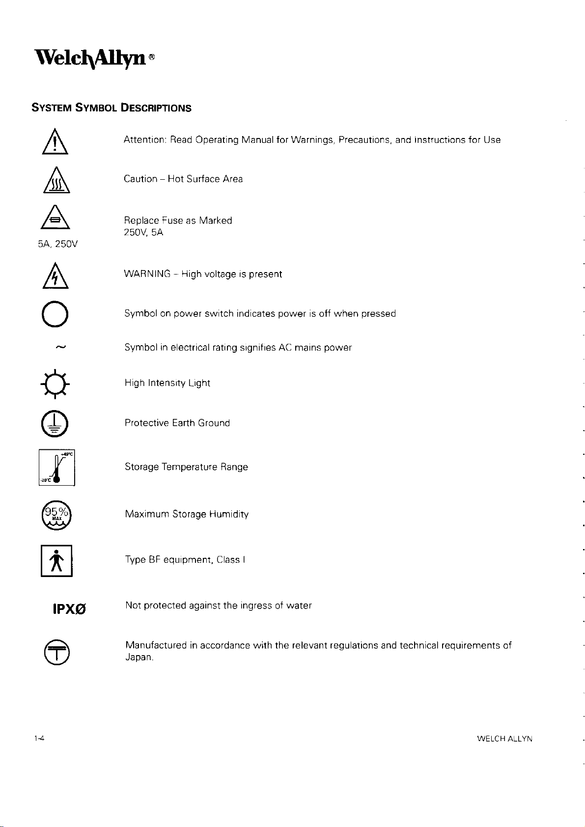
SYSTEM SYMBoL DEscRtPTtoNs
'
A
A
A
5A,250V
A
I
+
@
Attention: Read
Caution
Ra^la^a tr,,c6 ec lr,4ert orl
250V
WARNING - High voltage is
Symbol on
Symbol
High Intensity
Protective Earth G round
-
5A
in
Operating Manual for Warnings, Precautions, and Instructions for Use
Hot
Surface Area
power
electrical rating signifies AC mains
switch indicates
Light
present
power
is off when
power
pressed
|- ^.*l
| |f l
t4__l
@
tr
aPxg
Storage
Maximum Storage Humidity
Type
Not
Manufactured
Japan.
Temperature
BF equrpment, Class I
protected
against the
in accordance with the relevant regulations and
Range
ingress
of
water
technical
requirements
of
WELCH ALLYN
Page 9
WARNINGS AND PRECAUTIoNS
WARNING
e
/-\
l\
.
Keeo
.
Not suitable tor use in
nitrous
.
Disconnect from the
.
ELECTRICAL
.
Routinely examine the
with approved hospital
.
Do not olace the exoosed distal end of the
headlight
clothing,
.
High
energy
light
the
.
Use care
The
brilliant
Values {or Chemical Substances and Physical
3,1995).
.
Applied
42/EEC)
a Standards Council of Canada accredited
The
use of
.
During li{e
reolacement lamo.
.
The light source lamps are highly
failure or explosion of the
.
The light
operation.
powered
reach
out ol
oxide.
SHOCK
or other accessory.
or other
radiated light
outlet and to the tip
not
to
light
parts
attached to this equipment
(Europe),
non-approved
threatening
source
Temperatures
off.
patient.
of
the
patient
HAZARD. Do not remove the too cover
power
grade
material inadvertently
point
the distal end of the
output f
2) approved by a Nationally
procedures,
lamps
are
presence
before the discharge of a cardiac defibrillator.
guided
ot the instrument.
rom
components
lamp.
hot immediately
peak
of a flammable anesthetic mixture with air or
piug.
cord and
power
Failure
the unit can cause eye
cord and
to observe these
through endoscopes
it is recommended to have a backup Light source and an additional
pressurized,
in the light Sources approximately 60 seconds after the Light Source is
Do not
plug
Micro
Link@
placed
may compromise safety.
in front of the Micro Link@ Fiber or
fiber
or
Agent
should
be
Recognized Testing
laboratory
any damage or
after use,
if inspection reveals
use
with appropriate electrical
Fiber
precautions
may
headliqht
injury
Biological Exposure Indices, Final
and
approved 1) to the Medical Device Directive
(Canada)
allow the lamp to cool for five
fiber
or
give
directly
per
to the appropriate
improper handling may
bundle attached to either
may result in burns to skin,
rise to high temperatures in front
at the eye when unit is operating.
RP 27 .1
('1994
Laboratory
with
oxygen or
damage.
rating.
1995 Threshold Limit
(United
Replace only
fiber
bundle.
States),
medical standards.
cause
(5)
minutes after
a
of
March
dratt
(93/
and
3) by
premature
CAUTION
r
lA
PN: LB-MAN
.
.
.
Do not
Clogged or blocked vents
Keep
Fully
CLSERV
place
anythrng on top of the Light Source. Do
the Light Source clear
close the attenuator
Rev. A
not
may
cause Light Source overheating and
of any
obstructions.
before turning on the Light Source or when operational but not
liquid
store
above the
will result in thermal
Light Source.
shutdown.
in
use.
Page 10
Welc$11yn.
OPERATTNG lNsrRucloNs
CONTROLS
PowER ON/OFF swrrcH
Plug hospital
grounding
Press
Main Power
grade
Power
reliability.
Switch ON
Cord into
(l
pressed
grounded
a
in).
"Hospital
Grade" or
"Hospital
Use"
receptacle
to ensure
The lamp will
cannot
NOTE:
F|BER PoRT
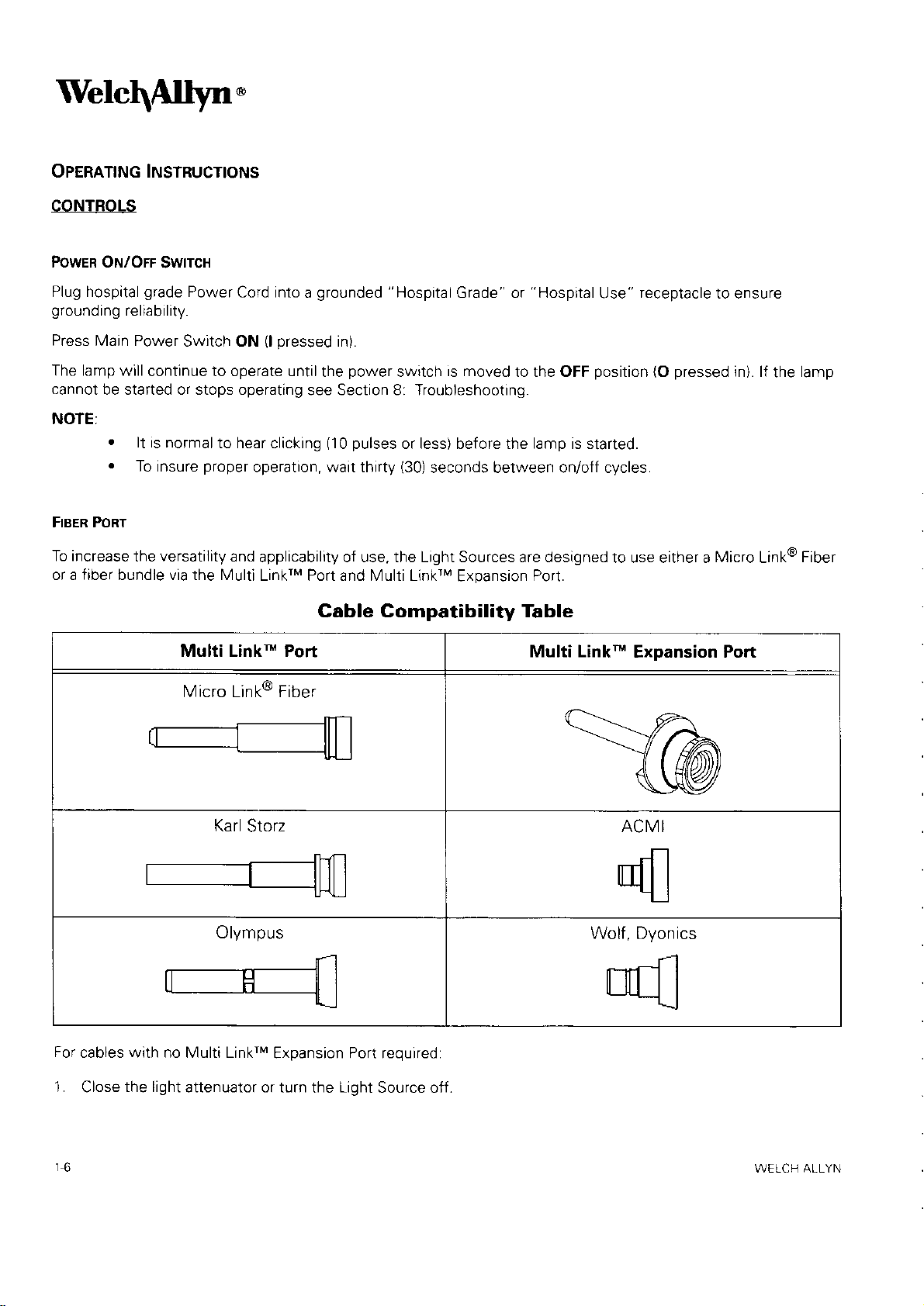
To increase
or a tiber bundle via the Multi
continue to operate untilthe
be started or stops operating
.
lt is normal
.
To insure
the
versatility
to hear clicking
proper
and
Multi Linkn Port
Micro Link@ Fiber
power
see Section 8: Troubleshooting.
(10
operation, wait thirty
applicability of use, the Light Sources are designed
LinkrM Port and Multi LinkrM
switch
pulses
is moved
or less) bef ore the lamp is started.
(30)
seconds between on/off cycles.
Expansion
to the OFF
Port.
position
Cable Gompatibility Table
Multi Link-
(O
pressed
to use either a
Expansion Port
in). lf
Micro
lamp
the
Fiber
Link@
Karl
Olympus
For
cables with no Multi LinkrM
1.
r6
Close
the light
attenuator or turn
Storz ACMI
Wolf , Dyonics
Expansion Port required:
Light
the
Source off.
WELCH ALLYN
Page 11
2.
Connect the
lnstrument
end of the
Micro Link@ Fiber or fiber bundle to the instrument.
Insert,
3.
4. Turn on Light
until fully engaged
Source.
MULT| L|NK'" ExpANsroN PoRT - lNsrALLATroN aNo
CAUTION: The Multi LinkrM Expansion Port contains
aouseo.
or
NOTE: The Multi
(snap
sound), the Lrght Source end
Adjust the light
LinkrM Expansion
attenuator to
Port must
the required illumination level.
(oproNAL)
UsE
optical
fully
be
Bundle.
Fiber
Port,
Light
perform
fiber
or
press
Source
the following operations:
bundle
from
and turn clockwise until
end
the fiber bundle into the Multi LinkrM Expansion Port.
of
To
use the
1.
Close the light attenuator or turn the Light Source off.
2. Remove, if
3. Insert the Multi LinkrM
4.
Connect the fiber bundle to the instrument.
5. Insert, until fully engaged,
l\4ulti
LinkrM Expansion Port
Micro
any,
Link@
Expansion
the
into
elements that
engaged
Multi
the
Multi
the
into
LinkrM
LinkrM
become
can
the Light Source before
Port.
it locks into
place.
Port.
damaged
if
inserting Fiber
dropped
6. Turn on Light
To remove
1. Turn
the Light Source off.
2. Remove
3. Turn
l\,4ulti
Source.
the Multi LinkrM Expansion Port
fiber
the
LinkrM Expansion
LrcHT ATTENUATToN
Adjust
bundle.
CoNTRoL
Moving the illumination wheel
LAMP LrFE lNDrcAToR
yellow
A
remaining
remaining
indicator light located on the console will light when there is approximately 50 hours
on the
hours have been exhausted the lamp will turn otf.
lamp. A
new
light
the
Port
* in"r"ur". light output. Moving the wheel down
up
Replacement Lamp
attenuator to the
perform
the following operations:
counter-clockwise until unlocked and remove.
should be available at this
required illumination level.
point.
-
reduces rrgnt output.
Once the
PN:
LB-MAN CLSERV
REV. A
Page 12
Welc\Allyn.
PRINCIPLES OF OPERATION
LtcHT SouRcE
The
Surgical
controls
event
that the
exceeds the engineering
power
REPLAcEMENT LAMPs
The lamps are high
fixture
to the optrcal
PowER
All
the electricity to the Light Source is
lamp, tans, and control
The
operational
MuLr
Internal,
designed to
reduce
Fiber and f iber bundles.
llluminators
indicators,
and
fan(s)
to the
which is designed to
LtNxn PoRT AND MULT| L|NK* ExpANsroN PoRT
lamp. After
platform.
Supply
temperatures at the optical
wrrx
life
to both the Multi LinkrM Port
produce
consist
power
and a
malfunctions
specifications, an internal thermal
cooling, the Light
pressure,
CoNTRoL ELEcrRoNtcs
of the lamp
the highest
high
allow both easy and rapid exchange
circuitry is
of an enclosure housing a high
supply
if adequate
or
intensity and long life Light Sources. They are mounted into a
provided
lamp life indicator
and
output
coupling
with
control electronics. Cooling
flow is
air
Sources
controlled through the ON/OFF switch.
by a custom designed, wattage regulated, switching
Multi
and
powers.
joints
may
be
are controlled
LinkrM Expansion
Internal
thereby
intensity lamp,
blocked
protection
to the
minimizing
and/or the internal temperature
restarted.
in
the
Port,
Light
mechanism will automatically shut off
field
by a lamp voltage monatoring
are
Sources are
the
proprietary
provided
is
well
as
patented
possibility
as ensuring
Power
coupling optics and
fans
of damage to
via internal fans. In
to energize and
and
optical
platform,
of
patented
precise
power
circuit.
heatsinks
Micro Lrnk@
user
the
the
device
lamp
alignment
operate
mechanics
designed to
the
supply.
1B
WELCH
ALLYN
Page 13
SERVTCE
CLEANTNG
1. Prior
to cleaning, turn the
power
switch OFE and disconnect
power
the wall outlet.
2.
Clean the external surfaces by wiping wrth a cloth dampened with 10%
r
Routinely inspect
.
Follow the manufacturer's instructions when Cleaning
and clean allair
intakes
/
out flows at the rear
fiber
the
source.
the
power
plug
the
cord with a cloth dampened with 107o
WET.
power
source into a wall outlet until it is thoroughly
bleach solution and
Wipe
3.
NOT RECONNECT
4.
DO NOT wipe down any lenses or windows.
DO NOT
5.
SURGtcAL ILLUMtNAToR
The
console may be cleaned using a clean soft cloth with
Enzymatic Solution
lsopropyl
Hydrogen
Alcohol
Peroxide
2% G lutaraldehyde
(Enzol)
3% USP
Solution
following
the
Soap and Water
'lOo/o
bleach sotutton
and
water
source
of the chassis
from
both the Light Source and
bleach solution. DO NOT
for lint
or other debris.
IMMERSE.
bundles or accessories used with the light
water.
NOT IIVIMERSE.
DO
DO
dry.
cleaning agents:
CAUTION: Do not splash cleaning agents into
MULT| L|NK* ExPANsroN PoRT
The outside surfaces may
be cleaned
with
a soft cloth using the
isopropyl Alcohol
Soap
glass
The
A
cotton swab
Blow with
NOTE: Use care in
Water
and
surfaces may be cieaned by the following methods:
moistened
with lsopropyl Alcohol
dry compressed air
cleaning the optical
surfaces
PN: LB-MAN CLSERV Rev. A
openings,
any
of the
seams or electrical components.
following:
Multi
LinkrM Expansion
Port
prevent
to
scratches.
1-9
Page 14
'IVelc$;1*.
TooLs REoUIRED
.
Slotted screwdriver, less
.
#1 Phillips
.
#2 Phillips
.
Open
.
Needle nose
.
Nut Driver Set - English
.
Nut Driver
.
Deep well
.
Non-conductive
.
Light output
100
.
Laght output meter - Labsphere Model FIMS-400P
Screwdriver, less than
Screwdriver, less than
wrench
end
Set
socket set and
Surgical
set- English or 5/16"
pliers
-
Metric
pot
adjusting tool - CL
power
llluminator
meter with head.
or 3/16", 114",5116"
or 1 Omm
"
than 6
wrench
long
long
6"
long
6"
-
(2)
100
CL
100
Surgical llluminator
Coherent Lasermate 1 D or equivalent
minator
Surgical llluminator
(meter),
or equivalent that measures in lumens
Head Model 1d10
-
CL 300 Surgical
-
CL
lllu-
o
CaIbrateo
RMS
Drgital Multimeter
(DMM)
1,10
WELCH ALLYN
Page 15
ThouBLESHoorNG
CL 1o0 SURGTCAL ILLUMTNAToR
Symptom Cause
Lamp fails to start and
fans are not ru nning.
Lamp fails to
fans
| ^'n^ ^h' '+^ ^al ^t.^.
Lo, r,P r,,urr u, I o, rel
operating
m in
running.
are
for a few
utes and
and
start
restarts after
coolrng.
power
No
voltage is <90 VAC Refer to Hospital Engineering department
Line
Fuses blown
Safety
Power supply failure Go to
Lamp not in light source
(audible
Defective lamp cable
(discolored,
prongs)
(audrble
Defective
(discolored,
prongs)
(no
audible clicking
Inadequate air
cooling,
lemperalUre
Fan failure Go to
Remedy
to unit Check
power
supply
Inspect, replace
Fuses" on
page
interlock open Check and tighten slotted screw
access door
"Test
#2: 100 WATT Power Supply" on
page
13
100W repiacement lamp, model 90133.
retest lamo cable.
clicking
heard)
Install a
Reolace and
bent or broken
power
bent or
heard)
supply
broken
Inspect wiring
power
supply.
clicking
heard)
(51mm)
Allow
"Test
#3:
Light
flow for
Source over
Ailow 2"
that air intake-outflow
blocked.
cord and outlet
retest. Go to
and
12.
if it is fine,
and
replace
clearance at back of unit;
vents
are clean
unit to cool
Cooling
and then restart
Fan " on
"Test
#1 :
Blown
on lamp f ixture
retest
and
insure
and not
'l
page
3.
Ind icator light on and
lamp shuts off
Replacement Lamp will
not
PN:
into
seat
LB-MAN CLSERV
Light Source
Bev. A
llluminator is overheating not
due to clearance.
Lamp rs at the end oi life, but
amber
LED is inoperative.
Lamp life exceeded.
Lamp cable defectrve.
Power
supply out of
calibration.
Lamp is not oriented correctly
Incorrect Replacement
Lamp
Verify operation of
fans. Clean fans and
components of dust.
Verify
go
not,
page
LED
to
13.
flickers
"Test
when it is
on
#4: LED/Overtemp
first
Install a 100W replacement lamp,
go
i'prongs
"Test
#6: Power Supply Calibration"
discolored. broken. or bent
are
14.
re-insert
and
lamp, model
Replace
To
page
Rotate lamp 180'
Install a 100W replacement
internal
turned on.
Switch" on
model
90'133.
90133.
lf
on
Page 16
Velc$11yn.
Symptom Cause Remedy
Lowlig ht oulpul
Fiber
bundle
Install in Light Source
will not
Damaged
or f iber bundle
Fiber
correctly.
Lamp near
Filter
contamrnated.
Minors dirty. Clean mirrors.
Broken mirrors. Replace
Misaligned mirrors
if
unit suffers damage)
Dirty
mooute.
Not
Micro
bundle
assembly on
or damaged
a compatible
not connected
end of usable
Fiber
Link@
life
platform
(possible
internal
f iber bundle
Check ends of
for
damage.
or fiber bundle. Go to
Test" on
Re-insert f iber bundle correctly.
lnstalla 100W replacement lamp, model 90133.
Clean or replace filter assembly as necessary.
lf above steps fail to improve output, replace and
retest
Inspect, clean, and replace if necessary.
"Operating
See
Replace with new Micro Link@ Fiber
page
platform.
platform.
Use compatible bundle design
Install/Femove
Expansion Port
Multi LinkrM
"Operatrng
See
Micro
'13.
Fiber
Link@
"Test
#5: Micro Link@ Fiber
Instructions" on
Instructrons"
fiber bundle
or
page
page
on
6
6
Multi
installed
Audible
arcing
lamp
CL lOO SURGICAL ILLUMINAToR DISASSEMBLY
NOTE: For all tests, remove 9 screws from top cover.
NOTE: Do not operate unit
TEST #1: BLowN
The
Diagram on
Replace
the end of the
when
where it contacts the fuse.
"
clicking " or
sound
ignition
purpose
page
and
prong
the
No
during
of this test is to determine the source of a short circuit causing fuses to blow. Refer to the Block
retest the fuses. lf
the
process
with
FUsEs
47.
fuse
and the
of the fuse holder makes
glass
krM Expansion Port
Lin
problem
the top cover removed
functions normally, inspect fuses that were blown. lf solder is melting out of
unit
is not blackened,
poor
remove
contact with
Remove Multi LinkrM
Normal
for
more than 5 minutes or the unit
and
the
operation
replace
fuse. The
the
power
prong
Fxpansion
entry
will look discolored and
Port
will
overheat.
module. This fault
pitted
occurs
WELCH ALLYN
Page 17

lf
fuse
the
replace
blows agarn, Inspect
visually
any
defective components.
the
power
supply and the wiring tor
damaged or burnt components. Remove
and
lf visual
Inspection
does
not
yield
any evidence
IEST #2: lOO WATT PowER SUPPTY
Verify operating voltage is
J2 terminals. When
Verify the lamp
lf voltage is
lf voltage is not
access door is closed.
present,
present,
present
power
reprace
inspect the f
on
is
applied to the unit, verify the
and retest
TEST #3: CooLING FAN
purpose
The
Visually
cover and inspect fan.
lf fan is inoperative
.
lf
voltage is
.
lf voltage is not
of this test ls to verify
inspect for a broken tan.
Replace any
and not broken, measure
present,
replace and retest fan.
present,
replace
When the unit is
IEST #4: LED/OVERTEMP SwITcH
purpose
The
of
this
test
is
to veriiy
of damage, remove and replace
power
supply input
terminals. Connect meter and
operating
power
uses,
supply.
wiring,
power
entry module, line filter,
the operatton of the lamp
broken
powered
fans.
up,
using DMM set for Volts DC for 12VDC
power
retest
and
proper
operation
supply.
of the LED.
cooling
look for
voltage
is displayed on the meter. NOTE:
power
and
supply
interlock
and retest.
to volts AC
set
switch.
tan.
a fan not turning. lf found, remove
fan
on
connector.
to J1 and
top
Visually inspect
and LED with DMM
.
lf
the DMM reading does not
r
lf
DMM reading matches
TEST #5: MIcRo
purpose
The
With
the
dramete'
.
lf
the intensity of light is not
not
cause the shape to change,
.
lf
the intensity is not
that LED/overtemp
set to the Diode
LINK@
FIBER lEsT
of this test is to verify
illuminator
to the
on, connect the fiber and
largest
stze.
consistent with alternating light
above, replace and retest
Over the same distance, adjust
focused.
lt any spot irregularities
connector.
switch harness is connected
Scale.
match,
DMM
replace
and retest
should read = .7VDC.
the
to the
LED harness
the
power
the operation of the Micro Link@ Fiber.
headlight.
the
consistent throughout the light
headlight
the
is the most likely
Over a distance of at least five teet,
spot and rotating the distal end connector does
and dark
headlight
the
are
present,
to the smallest
hold
the
diameter spot. At this adjustment, the headlight is
headlight
steady while rotating
power
suppty.
cause of the
present,
rings
supply. Verify continuity of wiring
adjust the spot
fault
the fiber is broken
distal
the
at the distal
(black)
end
PN:
LB-MAN-CLSEBV Rev. A
1,13
Page 18

Welc\Allyn'
.
lf
location
the
test. Replace
.
lf
the
location
of the
the fiber if
of the
defects move, remove the fiber,
detects are still
defects remain stationary,
present.
the
fault
clean the
is within the headlight.
end
with
distilled water, reconnect
the unit, and
TEST #6: PowER
purpose
The
power
Apply
power
DMM to
turning the
DMM. Monitor
and 18.00v.
'
lf the voltage
o
supply. The
the Lamp Return
lf the voltage is less
lt the voltage is more
1-31
5-685-2993 or 1
SUPPLY CAL|BRAT|oN
of this test is
to unit, once
unit on. When the lamp ignites,
the voltage
is between 17.00VDC
verify
to
the
positive
lead
-
terminal on the
displayed on the f luke when
than 17.00VDC, remove
than 18.00DC,
31 5-685-4233, 7:00am-3:00pm(EST).
the operation
lamp
lights, connect
of DMM
to the
power
there is
and 18VDC, remove
contact the Welch Allyn Technical
of the
the DIVIV
HV+
supply. WARNING: Do not
approximately 25kV on the
and replace
power
terminal on
the LED first turns
and
supply.
(set
to volts DC)
the
power
the
replace
to the lamp
power
supply and the negative lead
connect DIVM to wires
terminals which could damage
on. Verify the voltage is
supply
the lamp fixture.
Services Department
return
or
wires
cable
the unit for recalibration.
on the
of the
prior
between
at
to
the
17.00
WELCH ALLYN
Page 19

100
CL
PowER SUPPLY REMoVAL
'l
. Bemove the 9 screws securinq the
SURGTCAL
ILLUMTNAToR
DrsAssEMBLy
cover
toD
and
remove
the
cover.
2. Remove the 3 screws from the
3. Disconnect
4. Remove
wires from
the 2 screws
Screws
securing center
baffle to bottom
chass rs
J1 and J2 on the
from
the bottom chassis, securing the center baffle
w
Remove
5.
the
nut that
secures the center baffle to the back
bottom
side
of the back
power
supplv.
pane.
Disconnect
fan
(see
from
figure
connector
J4.
below).
lC"
oo
panel.
6.
PN:
Pull
supply.
LB
panel
back
MAN'CLSERV Rev.
out and move to the
A
platform
of the chassis to
side
garn
access to the back of the
power
115
Page 20

Welc$;1yt
7.
Remove the two white lamp cable wires and disconnect
'
the
4 wire
connector.
Remove
the supply and baff
le.
Remove the 4
8.
Reinstallation is the reverse
9.
of the two
return. Refer to " Photo 8"
PLATFoR'U REMovAL
'L
Remove
the bottom chassis and
2. Remove the 2 screws from
3. Remove the 4 screws f
4. As necessary, remove the 2
5. Remove the
movement
FRONT BEZEL REMoVAL
1.
Remove 9 screws securing top cover and remove the
the bottom chassis and
screws
lamp
9 screws securing top cover and remove the cover. Remove the 5 screws securing the front bezel to
platform.
of attenuator. Loosen
from
the corners of the
process
wires
cable
attaches to the
on
pull
front
the
rom
the corners of
screws
Reinstallation is the reverse
pull
front
with
page
24
panel
fan deflector
from
platform
panel
the
(+)
to connect the
from
out
the
the
screws and repositron as necessary.
out from chassis.
power
brown wire
assemblv.
f ilter
supply. Remove supply.
lamp
HV terminal and the shorter wire attaches to the
HV+
chassis.
platf
orm.
assembly.
process.
cover.
going
to J1 and the blue
lamp return
and
Remove
the
Installthe front
Remove
going
wire
-
terminals as shown.
lamp from
bezel and check
the 5 screws securing the
platform.
the
to J2.
for
The longer
(-)
proper
front
bezel to
lamp
from
the
the
power
remove
reverse
heat
the
reverse
switch noting wire localions. Push on
the black Rry from the LED wires where it mounts
process.
the
passing
process
through.
cover
top
shrink tubing
remove it
2. Remove
from
3. Using a sharp knife,
removed,
front bezel.
4. Installation is
superglue, loctite 430 to mount
light from the illuminator
FAN DEFLECTOR REMOVAL
1.
Remove 9 screws securing
2.
Remove
3.
Remove the overtemp switch f rom the fan
4.
Carefully
5.
Disconnect
Installation is
6.
wires
the bezel.
apply acetone to the LED and the front bezel to weaken the
the 5 screws securing the
remove
the connector and
switch
To
attach the LED, ensure both
LED.
and
front
with
installing new heat shrink tubing over fan connector.
RTV
Use
remove
bezel to the bottom chassis and
def
from
from the
sealant Dow Corning 737 to seal the LED,
the cover.
lector.
fan
the
wiring harness.
power
supply.
from
the
to
glue
bond
and
panel
and LED surfaces are clean. Use
pullfront panel
inside
the tront
remove the
to
bezel.
remove the LED from the
preventing
out from chassis.
switch
Once
any
WELCH ALLYN
Page 21

CHAssrs
FAN REMovAL
T. Remove
9 screws securing top cover
pane.
2. Remove heat
platform
the
3. Installation is the reverse
shrink tubing from the fan
mounts. Remove
process.
LED/OVERTEMP HARNESS REMovAL
1. Remove 9
the bottom chassis and
Remove
2.
harness at
Using a sharp
removed,
screws securing top cover and remove the
pulltront panel
the overtemp switch from the fan
platf
the
orm.
knife, remove
the black RTV from the LED wires where it mounts
apply acetone to the LED and
front bezel.
4.
Remove the 3 wire
lnstallation is
5.
Use superglue
light from
any
ties and
the reverse
(loctite
the illuminator to
process.
430)
to
remove
mount
remove
and
the cover.
connector.
the fan.
out from chassis.
lector
def
front
the
bezel to
the harness.
To attach
the
LED,
the LED. Use RTV sealant
pass
through.
See
figure
Remove 4
Disconnect
cover.
assembly.
and
Remove
Remove
weaken
ensure both the
(Dow
for routing
below
screws securing the
remove
the 5 screws
the wire tie
glue
the
panel
wire
the
to
bond and
and the
from the harness
ties
securing the front
f rom
the overtemp switch
the front bezel. Once
remove
LED
surfaces
Corning 737) to seal the LED
wires.
of
fan to
LED from
the
the back
at
bezel to
the
are
clean.
preventing
LAMP
CABLE
1. Remove I screws securing
back
PN:
LB-MAN-CLSERV Rev. A 1 17
REMovAL
panel.
Remove the nut securing
the top cover and
center baffle to the back
remove
the cover. Remove the 3 screws
panel.
Slide back
panel
from
the bottom of the
to
the side.
Page 22

Welc\ffiytt.
Remove
2.
from
cable
Installation is
3.
and connecting the shorter wire to the Lamp Return - terminal.
HV+
and the
INTERLoCK SwtrcH REMovAL
1. Remove the 9 screws securino the toD cover and
2. Disconnect the wires trom the interlock switch.
3. Remove the two nuts from the interlock switch and remove.
4. Instaliation is
PowER ENTRY MoDULE REMoVAI
Remove
1.
panel.
back
Remove
2.
3.
Remove the two nuts securing the PElvl to the back
nut from
the
power
the
the
Lamp Return - are
the reverse
9 screws securing the top cover and
Bemove
the 4 screws securing the chassis
the wire tie clamp secunng the
supply and remove the cable.
reverse
process
process,
nut securing center baffle to the back
the
with the
connected as shown
connecting the
longer
fan. Remove
cable wrre
remove
wires
remove
panel.
lamp
cable to the bottom chassis.
"Photo
in
the cover.
to the terminals
the cover.
the
Remove the
going
View
8" on
Remove
panel.
wires from PEM.
to the
the unit
page
marked
the 3 screws
PEM.
HV+
24.
terminal on
from
rear
the
COM and
from
Remove the lamp
power
the
and compare
NO.
the
supply
the
bottom of the
4.
lnstallation is the reverse
.
The
The
Rotate the screw
The
terminal marked as N on the PEN/]. The
nal on the
washer is located
star
washer is installed
flat
brown
wire is
PEM.
process
between the
on the other side of the
you
that
so
connected to
with the tollowing requirements:
PEM flange
later install the
can
the terminal marked
green
wire from the back
and the
panel
power
as
painted
is
and
cord retainer.
P on the PEM. The blue wire is connected to the
surface side
secured
panel
is connected to the
with
of the back
nut.
the
panel.
ground
termi-
r 1B WELCH ALLYN
Page 23

CL
100
SuRGrcAr ILLUMTNAToR REpAtR
Part
Number
PARTS Ltsr
Description
Photo #
Bubble
#
Ouantity
90133 l
LB-MAN.1OOW27OW MANUAL,
A0-10756
A0-10768
A0-1
101
4
071
0033 SCREW, #8-32
101-0022
016-0005 XLS,
-0068
1
01
A0-10683
A0-107
21 KAPTON TAPE,
A0-t
0828 PANEL,
u50087
u50081
u50085
u50075 l
A0-1071 1
A0-10856
213-0017
102-0012
44-10650
A4-10647
A0-10746
A0-10712
OOW R EPLACEM ENT LAMP
PANEL, BOTTOIV,
LABEL, WARNING, ILLUIVINATORS
SCREW,
scREW,
BUIV PER, RUBBER,
SEMS,
COVER,
FRONT,
l OOW INTERNAL
l OOW FAN DEFLECTOR
l OOW FILTE R
OOW ALIGNED PLATFORM
FAN,
PANEL,
POWER ENTRY MODULE/LINE
KE PS,
#6.32, W/CONICAL
WtRE
HARNESS,
POWER
OVERTEMP/LED
BAFFLE,
A0-'r0843 FOAM,
101-0062
-0007
207
105-0008
r06-0011
208-0016
44-10465
101-0073
010-0016 TUBING,
I01
0061
101 0038
SEMS, #6
GUARD,
CORD, RETAINING
STANDOFF, #8,.751
FUSE,
WIRE, PEM
SCREW, #8-32
HEAT SHRINK
SCREW,
1 OOW2TOW
SOLARTEC
27OW 1 1
PAINTED,
XLS
X 3/8, PHPS 1 4
#6-32
PHSS
X 1/4,
5/8 1 6 4
#6-32
TOE
CHASSIS, XLS
16
X
XLS
IOP
SOLARTEC
MODULE ASSEMBLY
PHPS
5i
CHASSIS 2 8 1
COVER, XLS 2 9 1
,]OOW
ASSEMBLY
ASSEMBLY
BACK WAVE PATTERN
FILTE R,
FUSED
WASHEB
ON/OFF, l OOW
SUPPLY XLS
SW]TCH ASSEMBLY 4
CENTER,
IGN
32 X 9/16
FAN,
5A SHEET III
XLS
TOR
PHPS
92MM
CLAMP
TO DIN
X 3/4", PHPS
BLACK
3/4"
#4-40X114, PHPS
PLUG,6/25
'l
'l
1
1 3 12
1 5
1 1
3 10 1
3
2 1
1t
4
2
I
1
3 12 1
3
3 14
3 15 1
3
3
3
3
4 20 1
4
4 40
5
5 24 1
5 25 I
5 26 4
6 27 2
6 28 1
6 29 4
6 30 z.za
6 31 4
7
13 1
to
17
18 4
'19
21 1
22 1
23
32 1
1
1
'l
1
1
4
PN:
LB-MAN.CLSERV ReV. A
Page 24

Welc$11*.
Number
Part
1 04
0006 WASHEH, COLOH
1
04-0008 WASHER,
104-0007
102-0001
104-0019
A0-10864
1 1 2-0001
Description Photo # Bubble
COAI II) 7 33 1
SEFRATED 7 1
WASHER, FLAT 7
NUT, H EX 7
WASHER, #4 tXItRNAI
CABLE,
CABLE
LAMP,
TIE,
SMALL
3OK
TOOTH
4"
# Ouantity
35 1
36 1
7 31 2
8 38
8 39 8
1
124
WELCH ALLYN
Page 25

PHoro 1
PHOTO 2
c
,,
=---|'
5
-/).
e
('
<-;-2
--.
lc"
"t-.......-o
a.--.-r
PN: LB MAN
CLSERV
BEv. A
1-21
Page 26

Welc$;1*'
PHoTo 3
19
12
10
11
PHoTo 4
14 18 17 15
21
WELCH ALLYN
Page 27

PHoTo
PHoTo 6
5
23
?4
31
30
PN: LB-MAN-CLSERV Rev. A
Page 28

Welc\ffi*'
PHoro 7
PHoTo 8
WELCH ALLYN
Page 29

CL 300 SuRGrcAr ILLUMTNAToR
Symptom Cause
Lamp fails
fans are not running.
Lamp fails to start and
tans are
to start and
running.
power
No
Line voltage is
Fuses
Satety interlock open Check and tighten slotted screw on lamp fixture
Power
board tailure
Lamp not in light source
(audible
Defective lamp cable
(discolored,
prongs)
(audible
Defective
(discolored,
prongs)
(no
audible
to unit Checf
<90
VAC Refer
blown
supply or auxiliary
clicking heard)
or
bent
clicking heard)
power
bent
clicking
broken
supply
or
broken
heard)
Remedy
power
to
Inspect, replace
"
Fuses
access door
"Test
Go to
page
an
Install a 270W replacement lamp, model 90125.
Replace and retest lamp cable.
Inspect wiring
power
supply.
supply cord a1d outlel
Hospital Engineering department
retest.
and
page
on
27
27.
#2:Auxiliary Board
if it is fine, replace and retest
and
"Test
Go to
Input Terminals
#1 :
Blown
Lamp shuts off after
seat
for a few
on and
Lamp
into
Light Source
operating
m In utes and restarts
Indicator lrght
lamp shuts off
Replacement
not
will
lnadequate air flow for
cooling, Light Source over
IemperaTUre
Fan failure
llluminator is overheating not
due to clearance.
Lamp is
amber LED is inoperative.
Lamp life exceeded. Install a 270W replacement lamp,
Lamp cable delective. Beplace
Lamp is not oriented correctly Rotate
lncorrect Replacement Lamp Install a 270W replacement lamp, model 90125.
at the end of
liie,
Allow 2"
that air
blocked.
Go to
Verify operation of
components of dust.
Verify LED flickers on when it is first turned on. lf
but
not, go
(51mm)
intake-outflow vents
Allow
"Test
"Test
to
prongs
if
lamp 180"
clearance at back of unit, insure
to cool and then restart
unit
#3.
Cooling
f4
Fan"
fans.
Clean
L ED Operatron " on
are discolored, broken, or bent.
re-insert
and
are clean and
page
on
fans
27.
and internal
page
model
90125.
not
27
.
PN. LB-MAN-CLSERV Rev. A
Page 30

Welc\ffiyr..
Symptom
Low light output Filter
contamrnated.
Mirrors are dirty. Clean
Broken mirrors. Replace
Misaligned mirrors
if
unit suffers damage)
Damaged Micro
or f iber bundle
Fiber
correctly.
Lamp
Fiber
bundle
install
will not
in Light Source
Not
a compatrble
Install/Remove
Expansion Port
Cause
assembly on
Link@
ndle
bu
near
not connected
end of usable
Multi LinkrM
platform
(possible
Fiber
life
fiber
bundle See
Remedy
Clean or replace filters as necessary.
mrrrors.
tne
platform.
lf above
platform.
retest
Check ends of Micro Link@
f or damage. Replace with new Micro Link@
fiber
or
Test"
Be-insert f iber bundle
Install a 270W replacement lamp, model 90125.
Use compatible bundle design
See
bundle. Go to
on
"Operating
"Operatrng
failto improve output, replace and
steps
Fiber
or
"Test
#5:
Micro Link@
page
28.
correctly.
on
page
page
Instructions" on
Instructrons"
fiber
6
6
bundle
Fiber
Fiber
Audible " clicking
"
or
arcrng sound during the
lamp ignition
process
Multi LinklM Expansion Port Bemove Multi LinkrM
problem
No
Normal operation
Expansion
Port
WELCH ALLYN
Page 31

CL
300
SURGTGAL ILLUMTNAToR DrsAssEMBLy
NOTE:
NOTE: Do not
lEsT #1:
The
Diagram on
Replace
the end of
when
where it contacts
lf visual inspection
wires
For
all tests, remove 9
operate unit with the top cover removed for more
BLowN FUsEs
purpose
of this test is to determine the source of a short
page
48.
and retest the fuses. lf unit functions normally, inspect fuses
fuse
the
the
prong
and the
of the fuse holder makes
the fuse.
does not
that connect
PCBA
and inspect fuses
.
lf
fuses
.
TEsr #2:
the
lf fuses are tine, remove
AuxtLtARy BoARD lNpur TERM|NALS
are blown,
Verity operating voltage is
termrnals.
J4
When
Verifv the lamo
power
access door
screws
glass
from
top cover.
is
not blackened, remove and replace
poor
yield
any evidence of damage,
auxi iary
remove
and
present
to the
board
replace
and
replace
on auxiliary board input termrnals. Connect meter
is applied to the unit
is
closed.
contact
power
with
supply. Replace
the PCBA
power
the
suppty.
the operating
than 5
circuit
causing fuses
that were blown. lf solder is melting
tuse.
the
remove
The
J2 and J3 from auxiliary board
fuses
auxiliary board
voltage, verify
minutes
power
the
prong
or the unrt
to blow.
entry
will look discolored
will
Refer
module. This
and turn system on. Remove
(part
no. A4-10670).
and set
is
it
displayed on the meter. NOTE:
to volts
overheat.
to the Block
out of
fault occurs
pitted
and
(blue
and brown
power
AC to J1 and
lf voltage is
lf voltage is
NOTE: lf
lEsr #3:
purpose
The
Visually inspect for
present,
not
lamp is not
replace
present,
on and
inspect the fuses, wiring,
CooUNG FAN
of this test is to verity
a broken fan. When the unit is
and retest auxiliary
voltage is
cover and inspect fan. Replace any
lf fan is inoperative
the lamp fan
.
lf voltage is
.
lf vo tage is not
#4:
IEST
The
LED OPERATIoN
purpose
Visually inspect that J1 is
Diode
the
Scale. DMM should read = .7VDC.
and not broken, measure
(exhaust)
this
of
and J101or the
present,
present,
test is to
replace and retest fan.
replace
verify
connected to the auxiliary board. Verify contrnuitv
board.
power
present,
check
if
the operation of the
powered
broken
fans
usrng DMM set
power
re-test
and
proper
supply
operation of the LED.
(intake).
auxilrary board.
entry
power
the
lamp
up,
module,
line filter, and interlock switch.
supply is defective.
cooling
fan.
look tor a fan not
for Volts
DC for
turning.
'l2VDC
wiring
of
lf found,
on fan connectors,
LED with
and
remove top
Jl
DMM set to
T is {or
PN: LB MAN-CLSERV
Rev. A
Page 32

Welc$1yn.
.
lf the DMM reading
.
f
TEST #5: MIcRo LINK@ FIBER TEST
purpose
The
reading matches
DMM
of this test is to verify the
not match, replace
does
above, replace and retest
and retest the LED
operation of the
auxiliary
the
Micro
board.
Link@
harness.
Fiber.
With
diameter to the largest
.
.
Over the same distance,
focused. lf
connector.
.
.
illuminator
the
intensity
lf the
not
cause the shape to change, the headlight is
lf the intensity is not consistent with
rstal
the d
any spot irregularities are
lf the location of the defects move, remove
Replace
test.
lf
location
the
on, connect the fiber and the headlight. Over a distance oi at least five feet, adjust the spot
size.
light
of
end.
the fiber if defects are still
of the defects remain
is not consistent
adjust the
headlight
present,
throughout the
the
hold
the
light
the
fiber,
alternating
to the smallest diameter spot.
present.
stationary, the
light
spot and
most likely
and dark
headlight
clean the end
fault is within the headlight.
steady
rotating
oJ the fault.
cause
rings
present,
are
At
while rotating the
with
distilled
the distal end connector does
the broken
this adlustment, the
water, reconnect
fiber is
headlight is
distalend
broken
(black)
the unit, and
at
WELCH ALLYN
Page 33

CL 300 SURGICAL
ILLUMTNAToR
DrsAssEMBLy
NOTE: All servicing requires removal
INTERNAL MODULE REMovAL
1. Remove
2. Remove the front bezel
3. Pull the internal module out of the
Installation
4.
will f t into
PowER SUPPLY REMovAL
1. Bemove
2. Remove the front bezel
3. Remove the air duct strap and air duct.
4.
Remove the 5 wires from the PCBA
Remove
5.
NOTE: Pull
termlnal's solder
the top cover.
is the reverse
recessed
the
the top cover.
wires f
the 7
or
pry
rom the
the wires straight up.
joint
on the
removing
by
process
area of the
by
of the
platform
with the
front
removing
auxiliary
power
power
supply board.
Puli or
Do
the
the
supply.
not rock
top cover. Remove the 9 screws and
5 screws securing the front bezel to the bottom chassis.
assembly.
portion
flat
edges on the
panel
and the
5 screws securing the front bezel to the bottom chassis.
(part
board
Rocking
pry
wire terminal straight up.
wire to remove it f rom the
the
remove.
to
gray
black dot in the
no. A4-10670).
remove
internal module
of the
gray plastic
to the bottom right.
power
the cover.
supply may damage the
aligned so
rt
Use bent tiD needle nose
PN: LB-MAN-CLSERV ReV. A
to
oliers
the terminal off.
orv
The handle
of a screwdriver
is
used as the f ulcrum.
Page 34

TVelc$1*.
6. Remove
7.
Installation is
.
P1
on
.
P2A- Used
.
P2
on
.
P3
on
.
P4
on
o
P5 on
.
P11 on
.
P12
on
(PARr
PCBA
'1.
Remove
2. Not
No. 44-10670)
location
the
the 4
screws
the reverse
power
power
power
power
power
power
power
power
from
supply to Jb
to confrgure
supply to J4
supplytoJl
supply
supply - red
as noted
and
-
supply - red
supply - black wire from red/black
REMovaL
remove
power
the
process
on
to 230v operation only
on
on PCBA
black wire from red/black
wire f rom red/black
or
above.
connectors
supply and
with
PCBA
PCBA
white
wires located
the
(part
no. A4-10670) - red
(parr
no. 44-10670)
(part
no. 44
wire from red/black
from J6, J7,
pullthe
-
pair
supply out of the front
as forrows:
NOT USED
-
brown wire
10670) bluewire
-
pair
housed
-
housed in
(thtn
pair
(thin
parr
J9, J
wire
10, J 1
1 , and J 12.
wire
in tubing
tubing
wire
pair)
pair)
remove.
to
3. Using a short #1
PCBA.
4.
Installation is
for
below
the reverse
proper
screwdriver, remove
process.
wire routing.
Use
the 4 screws from
the block diagrams as necessary
the corners of PCBA
(part
reconnect
to
no. A4-10670)
the wires.
and remove
See
figure
WELCH ALLYN
Page 35

IGNIToR REMovAL
1. Remove
Disconnect
2.
Remove 4
3.
center
Installation is
4.
baff
Installing
Reconnect
5.
.
Red wire to the lower center most terminal.
.
Black wire
-
lamp cable wire to the top left terminal
+ lamp cable wire to the top right terminal
the top cover.
lamp
the 2
cable wires and the
screws, securing rgnitor
module
red
and black
wires f rom
to the center baffle. Screws are
le.
the
reverse
process.
NOTE:
because
the screwdriver will not
and removing the screws lnto the ignitor to tap the
the
wires
to the
follows
as
lower
{see
outermost termina
figure for
(shorter
orientation).
.
wire).
llonger
wire).
holes
ignitor.
the
located
directly
prior
to installing the
Note the
wire locations.
on the other side of the
reach the lower screws,
ignitor
in the unit will
LINE FILTER REMOVAL
1. Remove the
PN: LB MAN
top cover.
CLSERV
REv. A
Page 36

Welc$1ytt'
2. Remove the screws
Hex head
secu
ring
screw
center
batfle to side of
securing the center baffle to the back
a
bottom cnassts
3. Remove the wires from both ends
panel
and the
XLS Rubber Bumper
rentdr baffle to
bottom chassis
a
Screw securing
center baffle to
panel
back
the line filter. Note location of wires.
of
bottom
chassis
(see
figure below).
4. Remove the 2 screws
Installation is the reverse
5.
.
The
end of the filter with 3 terminals is on the
.
The
.
The blue wires
termrnals.
CHAssrs
'1
. Remove
2.
3. Disconnect the
FAN REMovAL
Remove
unit, remove the fan on the
center baffle, then
(ground)
green
go
the top cover.
the 4 screws securing the fan and the wire
pull
fan
connector from the PCBA Auxiliary board
securing the
process
goes
wire
to the terminals
power
wires
the
line filter
with the
to the terminal directly
supply
out of
remove.
and
following requirements:
platform
nearest
side. To remove the lamp
grommet.
the
the
fans
guard.
side of the center baffle.
mounted to the metalsurtace.
on both ends.
NOTE: to
(part
The brown wires
remove
fan,
no.
the
push
the split
A4-10670) and
go
to the center most
fan from the lamp side of the
grommet
remove.
through the
WELCH
ALLYN
Page 37

4. InstalatlonisthereverseprocesswithJ11forthefanonthelampsrdeandJl0forthefanonthepower
supply side. Route
Wire Bouting
(part
the wires as shown in figures
on lgnitor and PCBA
no.
44- 10670)
below.
Chassis
Fan Wrre Routing
The label
on the lamp
POWER ENTRY
T. Remove
2. Remove
the top
the 3 screws securing the
baff le.
fan faces
side
MoDULE REMoVAL
cover.
out, the label on the
back
panel
to the
bottom
power
supply
side
faces in
chassis and the 1 screw back
(see
figure
panel
below).
to center
Remove
3.
Move
4.
Remove nuts from
5.
PN:
LB-MAN.CLSERV ReV. A
the 3 wire terminals from
panel
back
as necessary
to
power
gain
entry module.
access to
the PEM and remove module.
nuts
securing the
PEM
(power
entry module).
Page 38

Welc$11yr..
6. Installation is
.
.
o
PLATFoRM REMoVAL
'1
.
Remove the top cover
2. Remove
mooute.
3. Remove the two screws from
4. Remove the 4
5. Remove the lamp shroud f rom
Remove
6.
7. Installation is
internal module
lock
The
The flat
green
The
is connected
the front bezel by removing
the
reverse
the
washer is inserted
washer is inserted between
(ground)
to the terminal labeled N
screws securing the
platform
reverse
the
are
process
wire is
remove
and
and
the thermistor assembly from J12.
process.
installed.
Reattach the front bezel
with the following requirements.
between the
connected to the terminalsoldered directly to the metal surface. The blue wire
the lamp.
the 5 screws that secure it to the bottom chassis. Remove the internal
the air duct strap and remove the
plat{orm.
platform.
the
When installing
PEIV1
and the
non-painted
the
and the brown
the
painted
side of the back
wire
platform,
and check
side of the back
to the terminal marked P
duct.
verify that the shroud duct, the strap, and the
for
panel
attenuator
panel.
and the nut.
wheel
alignment.
.
Botate
freely,
FRoNT
1.
2. Remove
3. Noting the wire locations,
4.
5. Installation is the reverse
BLowER FAN REMovAL
2. Remove
3. Remove the air duct strap
BEZEL REMoVAL
Remove the top cover.
Using a sharp knife, remove
the LED and
set, apply opaque
the illuminator
1. Remove
wheel
the
loosen the
the 5 screws,
the
passing
the top cover.
front
the
across its adjustment range and if
platform
panel
front
sealant, Dow Corning 737 or equivalent, to the
bezel as
securing the
process
through
screws and
front
remove the wires from
the black
to loosen the
with
the LED.
described oreviouslv.
and duct as described above.
reposition
bezel to the bottom chassis.
RW from
qlue
the LED
the
power
the
the LED. Once removed, apply acetone to the area between
bond. Remove the LED.
glued
to the front
wheel moves freely,
the
platform
switch.
the wheel rotates freely.
so
Push
panel
using Loctite 430
around
area
continue, if
out the
the
power
LED to
it
does
switch.
equivalent.
or
prevent
not
move
Once
light from
I
-34
WELCH
ALLYN
Page 39

4.
Remove electrical connector
from PCBA
Jg
(part
no. 44-10670).
5. Remove the 2 nuts,
installation
6.
.
Spacers are installed
LAMP
CABLE
I Remove the
2. Open the lamp
3. Disconnect
4 Pull
lamo
5. Installation is
.
Bemove the nylon wire
is the reverse
REMoVAL
top cover.
access door, open the
the lamp cable wires from the ignitor.
cdble
out
reverse
the
througl-
Feed the wires through
Connect the shorter wire to the top left terminal on the ignitor.
terminal. Install the terminals between
screws, and spacers that
process
with
the
mount
the blower fan to the
following requirements:
on the screws between the bracket and the fan.
latch,
and disconnect cable.
la'np
the
process
tie
the space between the
with
from
the
access door.
following
the
lamp
cable.
two flat washers
the
requirements.
line filter
and the center chassis.
Connect the
(see
figure for
blower bracket.
longer wire
routing).
wire
to the top, right
Wire Routing
(part
no. 44-10670)
on lgnrtor and PCBA
PN: LB MAN CLSERV Rev. A
Page 40

Welc$11*'
CL 300 SURGTCAL ILLUMTNAToR REPATR PARTS Lrsr
Part Number Description
901 25 27W R EPLACEM tN I LAMP
tB-MAN-1OOW27OW MANUAL, 1
RM-LBL-023 LABEL, PROTECTIVE EARTH
A0-10755 BETEL
A0-10880
A0- 1 0797 EXTERNAL MODULE HOLDER, 27OW
A0-10714
A0-10768 LABEL, WARNING. ILLUMINATOFS 2 5
TOP
OOW2TOW
R,
COVE
SCREW,
PAINTED, XLS
LENGTHENED
SOLARTEC
GROUND
27A
Photo # Bubble # 0uantity
101-0033 SCREW, #8 32 X 3/8, PHPS 2
101-0022
SCBEW,
A0-10907
1
01-0068 SEMS,
016-0005 XLS, BUMPER, RUBBER, 5/8
#6-32 X 1/4,
CHASSIS BASE
#6-32 X
101,0062 SEMS, #6.32 X 9/16 PHPS
207-0007 GUARD,
FAN,
1 05-0008 CORD, RETAINING CLAMP
208-0016
A0-10904 BACK PANEL 2
213-0019 ROCKEB SWITCH,
A0-10906
A0- 1 0905
44 1 0670 PCBA, AUXILIARY 3
FUSE,
5A SHEET
BLOWER BRACI..ET
CENTER
BAFFLE 3
PHSS
2
2 8
PHPS 2 9 8
5/16,
2 10
2 11 I
92MM
2 12 2
2 13
III 1 2
ON/OFF,
WHITE 3
3
218 0003 IGNITOF, 270 WPI 3
A0-10864
105-0010 TENSION
101-0078
44-10680 WIRE HARNESS, LED/AU)?PS 3
112 0001 CABLE TIE, SMALL
A0-1 081 2 DUCI NOZZLE BLOWER, 27OW
A0-10814 STRAE AIR DUCT
17
u501
SCREW,4-40
27OW LAMP SHROUD SUB-ASSEN/ BLY
CABLE, LAMP, 3OK
RETAINER 3 22
WIRE
X 1/4, FHD,
StT 82DG
4"
u50111 27OW ADJUSTED POWER SUPPLY
213-0018 SWITCH,
1A2 0012 KEPS, #6_32,
21
0-0001
INTERLOCK,
WCONICAL
LIN E FILTER,
6.04,
POLE 4 30
SNGL
WASHER
FLANGE 4 32
3 21
3 23
3
4 26 1
4 27
4 28
4 29
4 31 3
2
3
4
6
7 8
15
16 1
17 1
Itt
18 1
19 1
20
24 1
25
'l
'I
1
1
1
1
4
4
1
1
4
1
,l
'1
1
,l
1
I
WELCH
ALLYN
Page 41

Part
Number Description Photo # Bubble # 0uantity
101-0059
213-0017
101-0084
POWER
SIMS,
ENIRY
SCREW,
u50123 27OW INTERNAL MODULE SUB ASSMB 4
u501 25 27OW FILTE R ASSEMBLY
-0061
1 01
SCREW, #4-40 X 1/4, PHPS
#6-32 X 1i4 PHPS 4
MODULE
FUS ED
#6 THD FRMG, PHPS
/
LINE
FILTER,
33
4
4 35
34
36
5 31
5
38 2
u501 1 5 27OOW ALIGNED PLATFORM 5 39
101-0073
44-10655 FAN,
A4-1067
44-10673 WIRE HARN ESS,
A4-1Q67 4 WIRE HARN ESS, AC/FILTER
1
09-0006
44 10675 WIRE HARNESS, AC/SWITCH
44 1
44-10676 WIRE HARN ESS, FILTER/PS
44-10678 WIRE HARNESS, AUXTPS
A4-10677 WIRE HARN ESS,
2 WIRE HARN ESS, FILTEF/GFOUND 6
0465
101-0085
44-10683 FAN, BLOWER, TEFLON WIRE 7
101 0083 SCEEW, 4.40 X 1 1/4",PHPS, SS 7
106-001 5 SPACER,
1
02-0008 NUT,
106-001 1
SCREW,
BUSHING,
SEMS,
102-0001 NUI
1 04 0007 WASHER, FLAT
1 04 0008 WASHER,
104-0019 WASHLR, t'4
101-0038 PLUG,6/25
1
04-0006 WASHER, COLOR COATED I 62 1
#8-32 X
3/4",
PHPS
5
BACK, 3 WIRE, 27OW 6 41 2
SWITCH/FILTER 6
44
46
47 1
48 1
AO
51
52
OPENED/CLOSED,
WIRE, PEM TO DIN
ON/OFF/AUX 7 50
4-40 X
PHPS 7
3/8,
.5OO
6
6
6
6
6
7
53
f4
STANDOFF,
hBD, 114
UNI
KEP, 4-40, HEX
#8, .751
od,
1l4l
7
1 55 2
7 56
54
HEX 8 57
I 58
SERRATED 8 59
EXILRNAL
TOOTF
I 60 2
8 61
2
4
4
1
1
4
1
2
2
4
1
'I
1
1
PN: LB-MAN
CLSERV
Rev. A
Page 42

Velc$11ytr.
PHoro 1
PHoro 2
1-3E
9
11
WELCH ALLYN
Page 43

PHoTo
PHoro 4
3
1725t8
PN:
LB-MAN CLSERV
Rev. A
33 32 34
30
Page 44

Welc$11ytt*
PHOTo
PHoro
5
6
WELCH ALLYN
Page 45

PHoro
7
PHOTo
8
PN:
LB-MAN CLSEBV ReV. A
Page 46

Velc\Allyn.
GLoSSARY oF
AC Alternating Current
COM
DMM Digital
Fiber
Optic Bundle
Leakage Current Usually a specified
LED Light Emitting Diode
Halide Any
Metal
NO Normally Open,
PC Board Printed Circuit Board
PEM Power Entry Module
FTV
TRMS
VDC Voltage
Xenon
TERMS
Found
Any
strands
electrical components
discharge light sources.
content ot the light source.
Room Temperature Vulcanizing Silicone
True Root Mean
An
suppressant
power
on
Multi Meter
number
of a
of cladded
number
of a
-Direct
elemental
in tungsten halogen
connectors,
of
glass
metallic compounds, usually
of
Found on switches
Squared
Current
gas
used commonly
switches, etc...
light transmission devices
fibers. Used
maximum amount of
when
subiected
lvletal halides are incorporated to
-
used to characterize
to deliver light from
indicating normally open terminatton.
used
lamps
indicating Common
characterized by use of
allowable current to
very high
to
accuracy of digital
in lighting
light emission in
or
wire
illuminator box to work area.
pass
electrical
iodides that are used
potentials.
produce
products.
gaseous
the destred spectral
multFmeters.
Used as an
discharge
termrnatron
multiple,
through
in
trace
hair
isolated
amounts
evaporant
lamps.
thin
in
WELCH ALLYN
Page 47

FINAL INSPECTIoN
purpose
The
source in
preventatrve
of
good
operating condition
marntenance rs to
should:
NOTE: Perform hypot and
ground
CL 100 SuRGrcAr ILLUMTNAToR
1.
Set
TIME
to start.
Turn
on the SYSTENiI. Begin the f ifteen
ing:
.
Drd the
.
Did the lamp
o
Are the fans running?
2. After the
yellow
f ifteen
LED light briefly?
start? Clicking before the
(1
5) minute burn-in insertthe POWERTESTFIBER intothe Port.
and measure the light output. Rotate
.
Does the connector insert
.
Does
the attenuator move smoothly?
.
Does the Lrght Output measure > 750 milliwatts? Light output < 375 is
lamp.
the
pro-actively
ensures that
it will
reduce or
perform
eliminate
reliably
and safely. Every six
future
continuity tests on the unrt before beginning the
(15)
minute BURN-lN
lamp ignites rs normal
proximal
the
end to
maximize
(10
clicks or
power
less).
output and
smoothly?
considered
problems.
Keeping the light
to
twelve
final inspection.
period.
Check
Open
for
the attenuator fully
check the following:
the end of the life of
months,
the
you
follow-
.
Turn
the system off and on again 3 more times. Does it light
lf testing has PASSED, continue. lf
unit
fails
testing, troubleshoot as
CL 3OO SURGIcAt ILLUMINAToR
IMPORTANT Clicking before the LAMP ignites is normal
The ILLUMINATOR must remain illuminated
Wait thirty
Turn
minimum of fortyjrve
re-strikes.
lf
testing
1.
Set
(30)
seconds between
ILLUMINATOR
the
off and on aoain three 13) more times. The ILLUMINATOR must
(45)
seconds eich trme before turning off . Usrng a
each
Clrcking bef ore the LAMP ignites is normal
has PASSED,
TIME
to start.
continue. lf unit fails testing, troubleshoot as necessary.
Turn
ILLUMINATOR.
on
for a minimum of forty-five
re-strike.
(10
Begin the fifteen
lowrng:
.
.
.
Did the
Did the
Are
yellow
lamp
start? Clicking bef ore the lamp ignites is normal
fans running?
the
LED
light
brief ly?
properly?
abruptly
and
necessary.
(10
clicks
less). Do not hot re-strike in succession.
or
(45)
seconds each time before turning off.
TIMER,
wait thirty
clicks or less). Does it light
(15)
minute BURN-lN
(10
clicks or less).
remain
(30)
promptly
period.
and
Check
illuminated for a
seconds between
properly?
for
the fol
PN:
LB-MAN-CLSEFV
Rev. A
1-43
Page 48

Welc\ffi*'
2. After
and measure the light
.
.
.
fifteen
the
Does
the connector
Does
the attenuator
Does the Lrght Output measure
lamp.
(15)
minute burn-in insert the POWER TEST FIBER into
>
361
proximal
lumens?
end
maximize
to
Light output < 200 is considered the end of the life of
output. Rotate the
insert
smoothly?
move
smoothly?
the
power
Port.
output
Open the attenuator f ully
and check the
following:
the
WELCH ALLYN
Page 49

SPEcIFIcATIoNS
Physical
Weight
Size
/
Weight
Slze
/
Space
Fin ish
Lamp
Power Requirements
Requirements
Type
Lamp
(CL
(CL
100)
300)
5.5" H x 11.25" W
"
Hx11.25"Wx12.75"
5.5
Minimum 2"
Painted surfaces
'100W
Xenon Arc
270W Short Arc
(51mm)
-
DC Metal Halide
x 11.25"
airspace
polyuretha
D/9.01b
D/1 1 .'1lb
ne
(140mmH
(140mmH
around top, back and sides
x 286mmW x 286mmD/4.0k9)
x 286mmW x 324mmD/5.0k9)
E lectrical
Amperage
Salety Compliance
U12601-1 2nd ed, CSAy'CAN-C22.2
lEC601-1
cD.
78737
lEC601-1-2:1993/EN 60601-1-2:1993
lEC601 2-1 8:1 996/EN 60601-2-1 8:1 996
IEC Classification
Type BF,
Continuous
l
Class
Operation
The
within the 93l42lEEC
EU Contact:
mark on this
CE
100-240 VAC 50/60H2
2.5 Amps @ 120V
4 Amps
:1988/EN 60601-'1 :1990 Amend. 2,
'120V
@
(Surgical
(Surgical
llluminator
llluminator CL 300)
No.601-1-M90,
(Class
lPXO
product
Medical Device Directive and 89/336EEC
indicates
it has been
that
E uropean
Welch Allyn Ltd.
County
Tel 353 46 67700
Fax
100)
CL
B), JIS T
353
1001 :1992,
tested
Regulatory Manager
Meath, Republic of lreland
46
to and conforms
EMC directive.
27128
with the
provisions
noted
PN: LB MAN
CLSEBV
RCv. A
Page 50

Welc$11ytt.
THEoRY oF OPERATToN
LIGHT SoURcE
The Light Sources consist of an enclosure housing, a
controls and
event that
exceeds the engineering specifications, an
power
REPLAcEMENT LAMPS
The lamps are high
lixture which is
to the oDtical Dlatform.
Powen Suppr-y
All the electricity to the Light Source
lamp, fans, and
The operational
MULT| LtNKn PoRT
Internal, to both the multi LinkrM
mechanics designed to
designed to reduce temperatures
Micro Link@
indicators,
the fan(s) malfunctions or
ramp.
to the
After
pressure,
designed
wrrH
CoNTRoL
control
life
of the
AND MULT|
Fiber
and
power
and a
coolrng,
to
circuitry is
lamp
produce
fiber bundles.
restart the Lrght Sources.
intensity
high
both easy and
allow
ELEcrRoNrcs
provided
the lamp life
and
L|NK*
Port
the
at the
supply with control electronics.
if
adequate
is
controlled
ExpANSroN PoRT
and
highest output
optical
air flow is blocked and/or the
internal thermal
long life Light Sources.
and
rapid
through the ON/OFF switch.
by a custom designed,
indicator
Multi LinkrM Expansion Port, are
powers.
coupling
high intensity lamp,
Cooling is
protectron
exchange
are controlled
Internal
thereby
Joints
mechanism will automatically shut off
They
in
field as well as ensuring
the
wattage regulated, switching
by a lamp voltage monitoring
to the
minimizing the
proprietary
internal temperature of the device
are
patented
Light
optical
provided
mounted into a
Power to energize and operate
coupling
Sources
platform,
via
internal
patented
precise
power
optics and
are fans and
possibility
of damage
user
fans. In the
circuit
lamp
a|gnment
the
supply.
heatsinks
to
1-46
WELCH ALLYN
Page 51

CL
100
SURGTCAL
ILLUMTNAToR
CrRcurr
DTAGRAM
100 240vAc
PN: LB MAN CLSERV BCv. A
El\,41
FILTEB
&
FUSE
2 VDC @0.6A
POWER
SUPPLY BLOCK
DIAGBAM
@ ]4VDC
t--r/ |
LAI'/P
I I
"\l
LAI\,4P ATERT
OUTPUT
O.I SHUT DOWN
INPUT
I
Page 52

\Velc\ffi*'
CL 3OO SURGICAL ILLUMINAToR
-:
CIRCUIT DIAGRAM
= i----.*.
>E
ca -3
148
WELCH ALLYN
 Loading...