

Page 1

Service Manual
CL 300 Surgical Illuminator
SolarTec Source 270
CL 100 Surgical Illuminator
SolarTec Source 100
PN: LB-MAN-CLSERV Rev. A
Welch Allyn Lighting Products
4619 Jordan Road
Skaneateles Falls, NY 13153-0187
Page 2

Rev. Description ECN # Date Approved
A New Release 0-1013 8/20/02 D. Rutan
Drawings, illustrations, and/or part numbers contained in this document are for reference purposes only. For current revisions
call the Welch Allyn Customer Service phone number listed in “Service Centers” on page 2 of this manual.
Page 3

Table of Contents
GENERAL INFORMATION - - - - - - - - - - - - - - - - - - - - - - - - - - - - - - - - - - - - - - - - - - - - - - - - - - - - - - - 1-1
TECHNICAL HELP INFORMATION - - - - - - - - - - - - - - - - - - - - - - - - - - - - - - - - - - - - - - - - - - - - - - - - - - - - 1-1
SERVICE CENTERS - - - - - - - - - - - - - - - - - - - - - - - - - - - - - - - - - - - - - - - - - - - - - - - - - - - - - - - - - - - 1-2
W
ARRANTY - - - - - - - - - - - - - - - - - - - - - - - - - - - - - - - - - - - - - - - - - - - - - - - - - - - - - - - - - - - - - - - 1-3
S
YSTEM SYMBOL DESCRIPTIONS - - - - - - - - - - - - - - - - - - - - - - - - - - - - - - - - - - - - - - - - - - - - - - - - - 1-4
W
ARNINGS AND PRECAUTIONS - - - - - - - - - - - - - - - - - - - - - - - - - - - - - - - - - - - - - - - - - - - - - - - - - - 1-5
Warning - - - - - - - - - - - - - - - - - - - - - - - - - - - - - - - - - - - - - - - - - - - - - - - - - - - - - - - - - - - - - - - - - - 1-5
Caution - - - - - - - - - - - - - - - - - - - - - - - - - - - - - - - - - - - - - - - - - - - - - - - - - - - - - - - - - - - - - - - - - - - 1-5
OPERATING INSTRUCTIONS - - - - - - - - - - - - - - - - - - - - - - - - - - - - - - - - - - - - - - - - - - - - - - - - - - - - - 1-6
Controls - - - - - - - - - - - - - - - - - - - - - - - - - - - - - - - - - - - - - - - - - - - - - - - - - - - - - - - - - - - - - - - - - - 1-6
P
OWER ON/OFF SWITCH - - - - - - - - - - - - - - - - - - - - - - - - - - - - - - - - - - - - - - - - - - - - - - - - - - - - - - - - - 1-6
F
IBER PORT - - - - - - - - - - - - - - - - - - - - - - - - - - - - - - - - - - - - - - - - - - - - - - - - - - - - - - - - - - - - - - - - - 1-6
M
ULTI LINK™ EXPANSION PORT - INSTALLATION AND USE (OPTIONAL) - - - - - - - - - - - - - - - - - - - - - - - - - 1-7
L
IGHT ATTENUATION CONTROL - - - - - - - - - - - - - - - - - - - - - - - - - - - - - - - - - - - - - - - - - - - - - - - - - - - - 1-7
L
AMP LIFE INDICATOR - - - - - - - - - - - - - - - - - - - - - - - - - - - - - - - - - - - - - - - - - - - - - - - - - - - - - - - - - - 1-7
Principles Of Operation - - - - - - - - - - - - - - - - - - - - - - - - - - - - - - - - - - - - - - - - - - - - - - - - - - - - - - - 1-8
L
IGHT SOURCE - - - - - - - - - - - - - - - - - - - - - - - - - - - - - - - - - - - - - - - - - - - - - - - - - - - - - - - - - - - - - - - 1-8
R
EPLACEMENT LAMPS - - - - - - - - - - - - - - - - - - - - - - - - - - - - - - - - - - - - - - - - - - - - - - - - - - - - - - - - - - 1-8
P
OWER SUPPLY WITH CONTROL ELECTRONICS - - - - - - - - - - - - - - - - - - - - - - - - - - - - - - - - - - - - - - - - - - 1-8
M
ULTI LINK™ PORT AND MULTI LINK™ EXPANSION PORT - - - - - - - - - - - - - - - - - - - - - - - - - - - - - - - - - 1-8
SERVICE - - - - - - - - - - - - - - - - - - - - - - - - - - - - - - - - - - - - - - - - - - - - - - - - - - - - - - - - - - - - - - - - - - 1-9
CLEANING - - - - - - - - - - - - - - - - - - - - - - - - - - - - - - - - - - - - - - - - - - - - - - - - - - - - - - - - - - - - - - - - - - 1-9
S
URGICAL ILLUMINATOR - - - - - - - - - - - - - - - - - - - - - - - - - - - - - - - - - - - - - - - - - - - - - - - - - - - - - - - - - 1-9
M
ULTI LINK™ EXPANSION PORT - - - - - - - - - - - - - - - - - - - - - - - - - - - - - - - - - - - - - - - - - - - - - - - - - - - 1-9
TOOLS REQUIRED - - - - - - - - - - - - - - - - - - - - - - - - - - - - - - - - - - - - - - - - - - - - - - - - - - - - - - - - - - 1-10
T
ROUBLESHOOTING - - - - - - - - - - - - - - - - - - - - - - - - - - - - - - - - - - - - - - - - - - - - - - - - - - - - - - - - - 1-11
CL 100 SURGICAL ILLUMINATOR - - - - - - - - - - - - - - - - - - - - - - - - - - - - - - - - - - - - - - - - - - - - - - - - - - 1-11
CL 100 S
T
EST #1: BLOWN FUSES - - - - - - - - - - - - - - - - - - - - - - - - - - - - - - - - - - - - - - - - - - - - - - - - - - - - - - - - 1-12
T
EST #2: 100 WATT POWER SUPPLY - - - - - - - - - - - - - - - - - - - - - - - - - - - - - - - - - - - - - - - - - - - - - - 1-13
T
EST #3: COOLING FAN - - - - - - - - - - - - - - - - - - - - - - - - - - - - - - - - - - - - - - - - - - - - - - - - - - - - - - - - 1-13
T
EST #4: LED/OVERTEMP SWITCH - - - - - - - - - - - - - - - - - - - - - - - - - - - - - - - - - - - - - - - - - - - - - - - - - 1-13
URGICAL ILLUMINATOR DISASSEMBLY - - - - - - - - - - - - - - - - - - - - - - - - - - - - - - - - - - - - - - - - 1-12
Page 4

TEST #5: MICRO LINK® FIBER TEST - - - - - - - - - - - - - - - - - - - - - - - - - - - - - - - - - - - - - - - - - - - - - - - - 1-13
T
EST #6: POWER SUPPLY CALIBRATION - - - - - - - - - - - - - - - - - - - - - - - - - - - - - - - - - - - - - - - - - - - - - 1-14
CL 100 SURGICAL ILLUMINATOR DISASSEMBLY - - - - - - - - - - - - - - - - - - - - - - - - - - - - - - - - - - - - - - 1-15
POWER SUPPLY REMOVAL - - - - - - - - - - - - - - - - - - - - - - - - - - - - - - - - - - - - - - - - - - - - - - - - - - - - - - 1-15
P
LATFORM REMOVAL - - - - - - - - - - - - - - - - - - - - - - - - - - - - - - - - - - - - - - - - - - - - - - - - - - - - - - - - - - 1-16
F
RONT BEZEL REMOVAL - - - - - - - - - - - - - - - - - - - - - - - - - - - - - - - - - - - - - - - - - - - - - - - - - - - - - - - - 1-16
F
AN DEFLECTOR REMOVAL - - - - - - - - - - - - - - - - - - - - - - - - - - - - - - - - - - - - - - - - - - - - - - - - - - - - - - 1-16
C
HASSIS FAN REMOVAL - - - - - - - - - - - - - - - - - - - - - - - - - - - - - - - - - - - - - - - - - - - - - - - - - - - - - - - - 1-17
LED/O
VERTEMP HARNESS REMOVAL - - - - - - - - - - - - - - - - - - - - - - - - - - - - - - - - - - - - - - - - - - - - - - - 1-17
L
AMP CABLE REMOVAL - - - - - - - - - - - - - - - - - - - - - - - - - - - - - - - - - - - - - - - - - - - - - - - - - - - - - - - - 1-17
I
NTERLOCK SWITCH REMOVAL - - - - - - - - - - - - - - - - - - - - - - - - - - - - - - - - - - - - - - - - - - - - - - - - - - - - 1-18
P
OWER ENTRY MODULE REMOVAL - - - - - - - - - - - - - - - - - - - - - - - - - - - - - - - - - - - - - - - - - - - - - - - - - 1-18
CL 100 S
CL 300 S
URGICAL ILLUMINATOR REPAIR PARTS LIST - - - - - - - - - - - - - - - - - - - - - - - - - - - - - - - - - - - - 1-19
URGICAL ILLUMINATOR - - - - - - - - - - - - - - - - - - - - - - - - - - - - - - - - - - - - - - - - - - - - - - - - - - 1-25
CL 300 SURGICAL ILLUMINATOR DISASSEMBLY - - - - - - - - - - - - - - - - - - - - - - - - - - - - - - - - - - - - - - 1-27
TEST #1: BLOWN FUSES - - - - - - - - - - - - - - - - - - - - - - - - - - - - - - - - - - - - - - - - - - - - - - - - - - - - - - - 1-27
T
EST #2: AUXILIARY BOARD INPUT TERMINALS - - - - - - - - - - - - - - - - - - - - - - - - - - - - - - - - - - - - - - - - 1-27
T
EST #3: COOLING FAN - - - - - - - - - - - - - - - - - - - - - - - - - - - - - - - - - - - - - - - - - - - - - - - - - - - - - - - - 1-27
T
EST #4: LED OPERATION - - - - - - - - - - - - - - - - - - - - - - - - - - - - - - - - - - - - - - - - - - - - - - - - - - - - - - 1-27
T
EST #5: MICRO LINK® FIBER TEST - - - - - - - - - - - - - - - - - - - - - - - - - - - - - - - - - - - - - - - - - - - - - - - - 1-28
CL 300 SURGICAL ILLUMINATOR DISASSEMBLY - - - - - - - - - - - - - - - - - - - - - - - - - - - - - - - - - - - - - - 1-29
INTERNAL MODULE REMOVAL - - - - - - - - - - - - - - - - - - - - - - - - - - - - - - - - - - - - - - - - - - - - - - - - - - - - 1-29
P
OWER SUPPLY REMOVAL - - - - - - - - - - - - - - - - - - - - - - - - - - - - - - - - - - - - - - - - - - - - - - - - - - - - - - 1-29
PCBA (
I
L
C
P
P
F
B
L
CL 300 S
PART NO. A4-10670) REMOVAL - - - - - - - - - - - - - - - - - - - - - - - - - - - - - - - - - - - - - - - - - - - - - 1-30
GNITOR REMOVAL - - - - - - - - - - - - - - - - - - - - - - - - - - - - - - - - - - - - - - - - - - - - - - - - - - - - - - - - - - - - 1-31
INE FILTER REMOVAL - - - - - - - - - - - - - - - - - - - - - - - - - - - - - - - - - - - - - - - - - - - - - - - - - - - - - - - - - 1-31
HASSIS FAN REMOVAL - - - - - - - - - - - - - - - - - - - - - - - - - - - - - - - - - - - - - - - - - - - - - - - - - - - - - - - - 1-32
OWER ENTRY MODULE REMOVAL - - - - - - - - - - - - - - - - - - - - - - - - - - - - - - - - - - - - - - - - - - - - - - - - - 1-33
LATFORM REMOVAL - - - - - - - - - - - - - - - - - - - - - - - - - - - - - - - - - - - - - - - - - - - - - - - - - - - - - - - - - - 1-34
RONT BEZEL REMOVAL - - - - - - - - - - - - - - - - - - - - - - - - - - - - - - - - - - - - - - - - - - - - - - - - - - - - - - - - 1-34
LOWER FAN REMOVAL - - - - - - - - - - - - - - - - - - - - - - - - - - - - - - - - - - - - - - - - - - - - - - - - - - - - - - - - 1-34
AMP CABLE REMOVAL - - - - - - - - - - - - - - - - - - - - - - - - - - - - - - - - - - - - - - - - - - - - - - - - - - - - - - - - 1-35
URGICAL ILLUMINATOR REPAIR PARTS LIST - - - - - - - - - - - - - - - - - - - - - - - - - - - - - - - - - - - - 1-36
Page 5

GLOSSARY OF TERMS - - - - - - - - - - - - - - - - - - - - - - - - - - - - - - - - - - - - - - - - - - - - - - - - - - - - - - - 1-42
F
INAL INSPECTION - - - - - - - - - - - - - - - - - - - - - - - - - - - - - - - - - - - - - - - - - - - - - - - - - - - - - - - - - - 1-43
CL 100 SURGICAL ILLUMINATOR - - - - - - - - - - - - - - - - - - - - - - - - - - - - - - - - - - - - - - - - - - - - - - - - - - 1-43
CL 300 S
URGICAL ILLUMINATOR - - - - - - - - - - - - - - - - - - - - - - - - - - - - - - - - - - - - - - - - - - - - - - - - - - 1-43
SPECIFICATIONS - - - - - - - - - - - - - - - - - - - - - - - - - - - - - - - - - - - - - - - - - - - - - - - - - - - - - - - - - - - 1-45
T
HEORY OF OPERATION - - - - - - - - - - - - - - - - - - - - - - - - - - - - - - - - - - - - - - - - - - - - - - - - - - - - - - 1-46
LIGHT SOURCE - - - - - - - - - - - - - - - - - - - - - - - - - - - - - - - - - - - - - - - - - - - - - - - - - - - - - - - - - - - - - - 1-46
R
EPLACEMENT LAMPS - - - - - - - - - - - - - - - - - - - - - - - - - - - - - - - - - - - - - - - - - - - - - - - - - - - - - - - - - 1-46
P
OWER SUPPLY WITH CONTROL ELECTRONICS - - - - - - - - - - - - - - - - - - - - - - - - - - - - - - - - - - - - - - - - - 1-46
M
ULTI LINK™ PORT AND MULTI LINK™ EXPANSION PORT - - - - - - - - - - - - - - - - - - - - - - - - - - - - - - - - 1-46
CL 100 SURGICAL ILLUMINATOR CIRCUIT DIAGRAM - - - - - - - - - - - - - - - - - - - - - - - - - - - - - - - - - - - 1-47
CL 300 S
URGICAL ILLUMINATOR CIRCUIT DIAGRAM - - - - - - - - - - - - - - - - - - - - - - - - - - - - - - - - - - - 1-48
Page 6

Page 7

GENERAL INFORMATION
The Welch Allyn CL 100 Surgical Illuminator and the Welch Allyn CL 300 Surgical Illuminator provide brilliant
illumination for the physician and surgeon. The lamps produce high intensity light nearly identical to the spectrum
of sunlight. Special features include the ability to use either a Cogent Optics Micro Link® Fiber or a conventional
fiber bundle.
T
ECHNICAL HELP INFORMATION
Only fully trained and properly equipped personnel should perform all service and repairs, using genuine
replacement parts and correct procedures. Failure to do so will invalidate the product warranty and could
compromise instrument safety and performance.
Read and understand all safety warnings and service notes printed in this Service Manual and the Operating
Manuals, part number LB-MAN-100W270W. If there is any doubt about any precaution or procedure, for phone
help, or to order additional copies of the Operating Manual, contact:
Customer Service
Welch Allyn, Inc.
4619 Jordan Road, PO Box 187
Skaneateles Falls, NY 13153-0187 USA
Telephone: 1-315-685-2993 or
1-866-801-8428
FAX: 1-315-685-2999
Techncial Assistance
Telephone: 1-315-685-4233, 7:00am-3:00pm(EST)
When calling, refer to the model number shown on the data label, found on the back of your Surgical Illuminator.
Technical assistance is contained in “Troubleshooting” on page 11 of this manual.
PN: LB-MAN-CLSERV Rev. A 1-1
Page 8

SERVICE CENTERS
If you have an equipment problem that you cannot resolve, you may call the Welch Allyn Service Center nearest
you for assistance. Technical service support is available by telephone on normal business days at the phone
numbers listed below. If you are advised to return a product to Welch Allyn for repair or routine maintenance,
schedule the repair with the service center nearest you.
BEFORE RETURNING A PRODUCT FOR REPAIR YOU MUST OBTAIN AUTHORIZATION FROM WELCH
ALLYN. AN RMA (RETURN MERCHANDISE AUTHORIZATION) NUMBER WILL BE GIVEN TO YOU BY OUR
SERVICE PERSONNEL. BE SURE TO NOTE THIS NUMBER ON THE OUTSIDE OF YOUR SHIPPING BOX.
RETURNS WITHOUT AN RMA NUMBER WILL NOT BE ACCEPTED FOR DELIVERY.
USA CUSTOMERS
Welch Allyn, Inc., U.S.A. Welch Allyn, Ltd., Canada
4619 Jordan Road 160 Matheson Blvd. E., Unit #2
Skaneateles Falls, NY 13153-0187 Mississauga, Canada L4Z 1V4
Tel: 1-315-685-2993 Tel: 905-890-0004
Fax: 315-685-2999 Fax: 905-890-0008
INTERNATIONAL CUSTOMERS
Welch Allyn, GmbH Welch Allyn, Ltd., Singapore
Zollerstrasse 2-4 300 Beach Road, #25-08
72417 Jungingen, Germany, The Concourse
Tel: 011-49-7477-9271-73 Singapore 199589
Fax: 011-49-7477-9271-93 Tel: 011-65-291-0882
Welch Allyn, Ltd., Australia Welch Allyn, China
Metro Center Room 708, 227 Huang Pi Road, North
Unit 5 38 South Street Central Plaza
Rydalmere, NSW 2116, Australia Shanghai 200003
Tel: 011-61-294-183-155 P.R. China
Fax: 011-61-294-183-650 Tel: 011-86-21-63279631
Welch Allyn, Japan
Bon Marusan 8F, 3-5-1 Kanda
Jinbo-Cho, Chiyoda-Ku
Tokyo 101-0051
Japan
Tel: 011-813-5212-7391
Fax: 011-813-3261-7372
CANADA CUSTOMERS
Fax: 011-65-291-5780
Fax: 011-86-21-63279632
LATIN AMERICAN CUSTOMERS
MD International
11300 N.W. 41st Street
Miami, FL 33178 USA
Tel: 1-305-669-9003
Fax: 1-305-669-1971
1-2 WELCH ALLYN
Page 9

WARRANTY
Welch Allyn warrants the CL 300 or CL 100 Surgical Illuminator when new, to be free of defects in material and
workmanship and to perform in accordance with manufacturer’s specifications when subject to normal use and
service for a period of one year from date of purchase from Welch Allyn or an authorized agent. Welch Allyn will
either repair or replace any components found to be defective or at variance from manufacturer’s specifications
within this time at no cost to the customer. It shall be the purchaser’s responsibility to return the instrument to the
authorized distributor, agent, or service representative.
Welch Allyn warrants the lamp to be free of defects in materials and workmanship for a period of 6 months from
the date of purchase. This warranty does not cover the lamp for breakage or failure due to tampering, misuse,
neglect, accidents, improper installation, modification, shipping, or from improper maintenance, service, or
cleaning procedures.
This warranty is void if the instrument is not used in accordance with manufacturer’s recommendations or if
required service is performed by other than Welch Allyn or an authorized agent. Purchase date determines
warranty requirements. No other express or implied warranty is given.
PN: LB-MAN-CLSERV Rev. A 1-3
Page 10
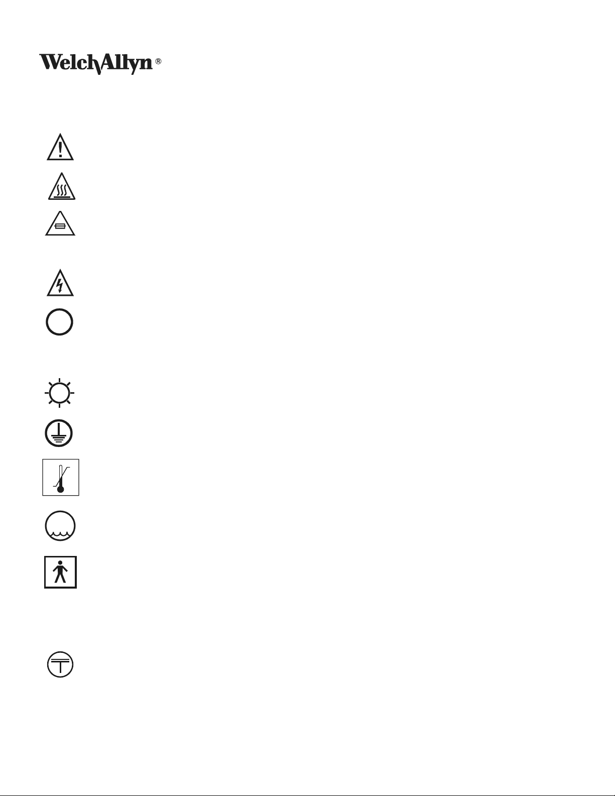
SYSTEM SYMBOL DESCRIPTIONS
Attention: Read Operating Manual for Warnings, Precautions, and Instructions for Use
Caution – Hot Surface Area
Replace Fuse as Marked
250V, 5A
5A, 250V
WARNING – High voltage is present
Symbol on power switch indicates power is off when pressed
~
o
-20 C
95%
MAX
IPXØ
+49 C
Symbol in electrical rating signifies AC mains power
High Intensity Light
Protective Earth Ground
o
Storage Temperature Range
Maximum Storage Humidity
Type BF equipment, Class I
Not protected against the ingress of water
Manufactured in accordance with the relevant regulations and technical requirements of
Japan.
1-4 WELCH ALLYN
Page 11

WARNINGS AND PRECAUTIONS
WARNING
• Keep out of reach of patient.
• Not suitable for use in the presence of a flammable anesthetic mixture with air or with oxygen or
nitrous oxide.
• Disconnect from the patient before the discharge of a cardiac defibrillator.
• ELECTRICAL SHOCK HAZARD. Do not remove the top cover.
• Routinely examine the power cord and plug. Do not use if inspection reveals damage. Replace only
with approved hospital grade power cord and plug with appropriate electrical rating.
• Do not place the exposed distal end of the Micro Link® Fiber or fiber bundle attached to either a
headlight or other accessory. Failure to observe these precautions may result in burns to skin,
clothing, or other material inadvertently placed in front of the Micro Link® Fiber or fiber bundle.
• High energy radiated light guided through endoscopes may give rise to high temperatures in front of
the light outlet and to the tip of the instrument.
• Use care not to point the distal end of the fiber or headlight directly at the eye when unit is operating.
The brilliant light output from the unit can cause eye injury per RP-27.1 (1994-1995 Threshold Limit
Values for Chemical Substances and Physical Agent and Biological Exposure Indices, Final draft March
3,1995).
• Applied parts attached to this equipment should be approved 1) to the Medical Device Directive (93/
42/EEC) (Europe), 2) approved by a Nationally Recognized Testing Laboratory (United States), and 3) by
a Standards Council of Canada accredited laboratory (Canada) to the appropriate medical standards.
The use of non-approved components may compromise safety.
• During life threatening procedures, it is recommended to have a backup Light source and an additional
replacement lamp.
• The light source lamps are highly pressurized, any damage or improper handling may cause premature
failure or explosion of the lamp.
• The light source lamps are hot immediately after use, allow the lamp to cool for five (5) minutes after
operation. Temperatures peak in the light Sources approximately 60 seconds after the Light Source is
powered off.
CAUTION
• Do not place anything on top of the Light Source. Do not store liquid above the Light Source.
• Clogged or blocked vents may cause Light Source overheating and will result in thermal shutdown.
Keep the Light Source clear of any obstructions.
• Fully close the attenuator before turning on the Light Source or when operational but not in use.
PN: LB-MAN-CLSERV Rev. A 1-5
Page 12
OPERATING INSTRUCTIONS
CONTROLS
POWER ON/OFF SWITCH
Plug hospital grade Power Cord into a grounded “Hospital Grade” or “Hospital Use” receptacle to ensure
grounding reliability.
Press Main Power Switch ON (I pressed in).
The lamp will continue to operate until the power switch is moved to the OFF position (O pressed in). If the lamp
cannot be started or stops operating see Section 8: Troubleshooting.
NOTE:
• It is normal to hear clicking (10 pulses or less) before the lamp is started.
• To insure proper operation, wait thirty (30) seconds between on/off cycles.
IBER PORT
F
To increase the versatility and applicability of use, the Light Sources are designed to use either a Micro Link® Fiber
or a fiber bundle via the Multi Link™ Port and Multi Link™ Expansion Port.
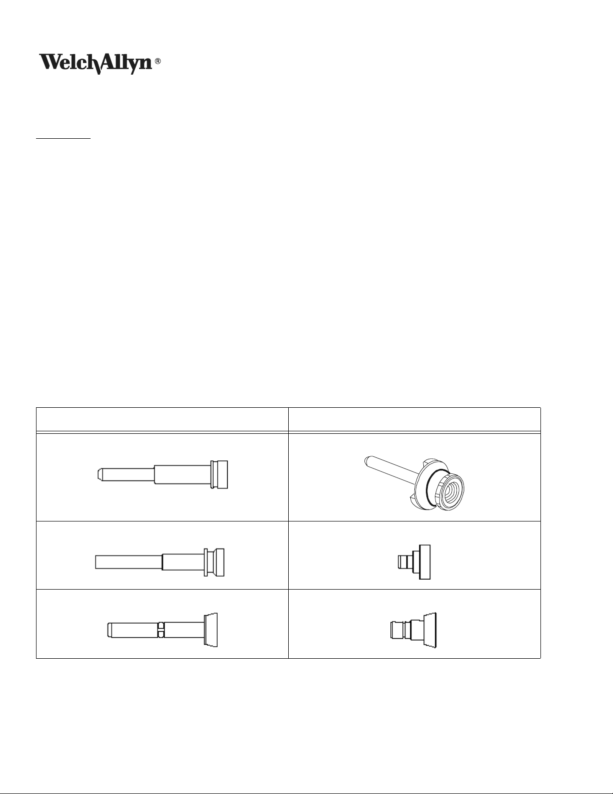
Cable Compatibility Table
Multi Link™ Port Multi Link™ Expansion Port
Micro Link
®
Fiber
Karl Storz ACMI
Olympus Wolf, Dyonics
For cables with no Multi Link™ Expansion Port required:
1. Close the light attenuator or turn the Light Source off.
1-6 WELCH ALLYN
Page 13

2. Connect the instrument end of the Micro Link® Fiber or fiber bundle to the instrument.
3. Insert, until fully engaged (snap sound), the Light Source end into the Multi Link™ Port.
4. Turn on Light Source. Adjust the light attenuator to the required illumination level.
M
ULTI LINK™ EXPANSION PORT - INSTALLATION AND USE (OPTIONAL)
CAUTION: The Multi Link™ Expansion Port contains optical elements that can become damaged if dropped
or abused.
NOTE: The Multi Link™ Expansion Port must be fully engaged into the Light Source before inserting Fiber
Bundle.
To use the Multi Link™ Expansion Port perform the following operations:
1. Close the light attenuator or turn the Light Source off.
2. Remove, if any, Micro Link
®
Fiber or fiber bundle from the Multi Link™ Port.
3. Insert the Multi Link™ Expansion Port, press and turn clockwise until it locks into place.
4. Connect the fiber bundle to the instrument.
5. Insert, until fully engaged, the Light Source end of the fiber bundle into the Multi Link™ Expansion Port.
6. Turn on Light Source. Adjust the light attenuator to the required illumination level.
To remove the Multi Link™ Expansion Port perform the following operations:
1. Turn the Light Source off.
2. Remove the fiber bundle.
3. Turn Multi Link™ Expansion Port counter-clockwise until unlocked and remove.
L
IGHT ATTENUATION CONTROL
Moving the illumination wheel up + increases light output. Moving the wheel down — reduces light output.
L
AMP LIFE INDICATOR
A yellow indicator light located on the console will light when there is approximately 50 hours
remaining on the lamp. A new Replacement Lamp should be available at this point. Once the
remaining hours have been exhausted the lamp will turn off.
PN: LB-MAN-CLSERV Rev. A 1-7
Page 14

PRINCIPLES OF OPERATION
LIGHT SOURCE
The Surgical Illuminators consist of an enclosure housing a high intensity lamp, proprietary optical platform, user
controls and indicators, and a power supply with control electronics. Cooling is provided via internal fans. In the
event that the fan(s) malfunctions or if adequate air flow is blocked and/or the internal temperature of the device
exceeds the engineering specifications, an internal thermal protection mechanism will automatically shut off
power to the lamp. After cooling, the Light Sources may be restarted.
R
EPLACEMENT LAMPS
The lamps are high pressure, high intensity and long life Light Sources. They are mounted into a patented lamp
fixture which is designed to allow both easy and rapid exchange in the field as well as ensuring precise alignment
to the optical platform.
OWER SUPPLY WITH CONTROL ELECTRONICS
P
All the electricity to the Light Source is controlled through the ON/OFF switch. Power to energize and operate the
lamp, fans, and control circuitry is provided by a custom designed, wattage regulated, switching power supply.
The operational life of the lamp and lamp life indicator are controlled by a lamp voltage monitoring circuit.
ULTI LINK™ PORT AND MULTI LINK™ EXPANSION PORT
M
Internal, to both the Multi Link™ Port and Multi Link™ Expansion Port, are patented coupling optics and mechanics
designed to produce the highest output powers. Internal to the Light Sources are fans and heatsinks designed to
®
reduce temperatures at the optical coupling joints thereby minimizing the possibility of damage to Micro Link
Fiber and fiber bundles.
1-8 WELCH ALLYN
Page 15

SERVICE
CLEANING
1. Prior to cleaning, turn the power switch OFF, and disconnect power source from both the Light Source and
the wall outlet.
2. Clean the external surfaces by wiping with a cloth dampened with 10% bleach solution. DO NOT IMMERSE.
• Routinely inspect and clean all air intakes / out flows at the rear of the chassis for lint or other debris.
• Follow the manufacturer’s instructions when Cleaning the fiber bundles or accessories used with the light
source.
3. Wipe the power cord with a cloth dampened with 10% bleach solution and water. DO NOT IMMERSE. DO
NOT RECONNECT WET.
4. DO NOT wipe down any lenses or windows.
5. DO NOT plug the power source into a wall outlet until it is thoroughly dry.
S
URGICAL ILLUMINATOR
The console may be cleaned using a clean soft cloth with the following cleaning agents:
Enzymatic Solution (Enzol)
Isopropyl Alcohol
Hydrogen Peroxide 3% USP
2% Glutaraldehyde Solution
Soap and Water
10% bleach solution and water
CAUTION: Do not splash cleaning agents into any openings, seams or electrical components.
M
ULTI LINK™ EXPANSION PORT
The outside surfaces may be cleaned with a soft cloth using the following:
Isopropyl Alcohol
Soap and Water
The glass surfaces may be cleaned by the following methods:
A cotton swab moistened with Isopropyl Alcohol
Blow with dry compressed air
NOTE: Use care in cleaning the optical surfaces of the Multi Link™ Expansion Port to prevent scratches.
PN: LB-MAN-CLSERV Rev. A 1-9
Page 16

TOOLS REQUIRED
• Slotted screwdriver, less than 6” long
• #1 Phillips Screwdriver, less than 6” long
• #2 Phillips Screwdriver, less than 6” long
• Open end wrench set - English or 5/16”
• Needle nose pliers
• Nut Driver Set - English or 3/16”, 1/4”, 5/16”
• Nut Driver Set - Metric or 10mm
• Deep well socket set and wrench (2) - CL 100 Surgical Illuminator
• Non-conductive pot adjusting tool - CL 100 Surgical Illuminator
• Light output power meter with head. Coherent Lasermate 1D or equivalent (meter), Head Model 1d10 - CL
100 Surgical Illuminator
• Light output meter - Labsphere Model FIMS-400P or equivalent that measures in lumens - CL 300 Surgical Illuminator
• Calibrated RMS Digital Multimeter (DMM)
1-10 WELCH ALLYN
Page 17

TROUBLESHOOTING
CL 100 SURGICAL ILLUMINATOR
Symptom Cause Remedy
Lamp fails to start and
fans are not running.
Lamp fails to start and
fans are running.
Lamp shuts off after
operating for a few
minutes and restarts after
cooling.
No power to unit Check power supply cord and outlet
Line voltage is <90 VAC Refer to Hospital Engineering department
Fuses blown Inspect, replace and retest. Go to “Test #1: Blown
Fuses” on page 12.
Safety interlock open Check and tighten slotted screw on lamp fixture
access door
Power supply failure Go to “Test #2: 100 WATT Power Supply” on
page 13
Lamp not in light source
(audible clicking heard)
Defective lamp cable
(discolored, bent or broken
prongs)
(audible clicking heard)
Defective power supply
(discolored, bent or broken
prongs)
(no audible clicking heard)
Inadequate air flow for
cooling, Light Source over
temperature
Fan failure Go to “Test #3: Cooling Fan” on page 13.
Install a 100W replacement lamp, model 90133.
Replace and retest lamp cable.
Inspect wiring and if it is fine, replace and retest
power supply.
Allow 2” (51mm) clearance at back of unit; insure
that air intake-outflow vents are clean and not
blocked. Allow unit to cool and then restart
Illuminator is overheating not
due to clearance.
Lamp is at the end of life, but
amber LED is inoperative.
Indicator light on and
lamp shuts off
Replacement Lamp will
not seat into Light Source
PN: LB-MAN-CLSERV Rev. A 1-11
Lamp life exceeded. Install a 100W replacement lamp, model 90133.
Lamp cable defective. Replace if prongs are discolored, broken, or bent.
Power supply out of
calibration.
Lamp is not oriented correctly Rotate lamp 180° and re-insert
Incorrect Replacement Lamp Install a 100W replacement lamp, model 90133.
Verify operation of fans. Clean fans and internal
components of dust.
Verify LED flickers on when it is first turned on. If
not, go to “Test #4: LED/Overtemp Switch” on
page 13.
To go “Test #6: Power Supply Calibration” on
page 14.
Page 18

Symptom Cause Remedy
Low light output
Fiber bundle will not
install in Light Source
Damaged Micro Link
or fiber bundle
®
Fiber
Check ends of Micro Link® Fiber or fiber bundle
for damage. Replace with new Micro Link
®
Fiber
or fiber bundle. Go to “Test #5: Micro Link® Fiber
Test” on page 13.
Fiber bundle not connected
Re-insert fiber bundle correctly.
correctly.
Lamp near end of usable life Install a 100W replacement lamp, model 90133.
Filter assembly on platform
Clean or replace filter assembly as necessary.
contaminated.
Mirrors dirty. Clean mirrors.
Broken mirrors. Replace platform.
Misaligned mirrors (possible
if unit suffers damage)
Dirty or damaged internal
If above steps fail to improve output, replace and
retest platform.
Inspect, clean, and replace if necessary.
module.
Not a compatible fiber bundle See “Operating Instructions” on page 6
Use compatible bundle design
Install/Remove Multi Link™
See “Operating Instructions” on page 6
Expansion Port
Multi Link™ Expansion Port
Remove Multi Link™ Expansion Port
installed
Audible “clicking” or
No problem Normal operation
arcing sound during the
lamp ignition process
CL 100 SURGICAL ILLUMINATOR DISASSEMBLY
NOTE: For all tests, remove 9 screws from top cover.
NOTE: Do not operate unit with the top cover removed for more than 5 minutes or the unit will overheat.
EST #1: BLOWN FUSES
T
The purpose of this test is to determine the source of a short circuit causing fuses to blow. Refer to the Block
Diagram on page 47.
Replace and retest the fuses. If unit functions normally, inspect fuses that were blown. If solder is melting out of
the end of the fuse and the glass is not blackened, remove and replace the power entry module. This fault occurs
when the prong of the fuse holder makes poor contact with the fuse. The prong will look discolored and pitted
where it contacts the fuse.
1-12 WELCH ALLYN
Page 19

If the fuse blows again, inspect the power supply and the wiring for damaged or burnt components. Remove and
replace any visually defective components.
If visual inspection does not yield any evidence of damage, remove and replace power supply and retest.
T
EST #2: 100 WATT POWER SUPPLY
Verify operating voltage is present on power supply input terminals. Connect meter and set to volts AC to J1 and
J2 terminals. When power is applied to the unit, verify the operating voltage is displayed on the meter. NOTE:
Verify the lamp access door is closed.
If voltage is present, replace and retest power supply.
If voltage is not present, inspect the fuses, wiring, power entry module, line filter, and interlock switch.
EST #3: COOLING FAN
T
The purpose of this test is to verify the operation of the lamp cooling fan.
Visually inspect for a broken fan. When the unit is powered up, look for a fan not turning. If found, remove top
cover and inspect fan. Replace any broken fans.
If fan is inoperative and not broken, measure using DMM set for Volts DC for 12VDC on fan connector.
• If voltage is present, replace and retest fan.
• If voltage is not present, replace and retest power supply.
T
EST #4: LED/OVERTEMP SWITCH
The purpose of this test is to verify proper operation of the LED.
Visually inspect that LED/overtemp switch harness is connected to the power supply. Verify continuity of wiring
and LED with DMM set to the Diode Scale. DMM should read ≈ .7VDC.
• If the DMM reading does not match, replace and retest the LED harness.
• If DMM reading matches above, replace and retest the power supply.
T
EST #5: MICRO LINK® FIBER TEST
The purpose of this test is to verify the operation of the Micro Link® Fiber.
With the illuminator on, connect the fiber and the headlight. Over a distance of at least five feet, adjust the spot
diameter to the largest size.
• If the intensity of light is not consistent throughout the light spot and rotating the distal end connector does
not cause the shape to change, the headlight is the most likely cause of the fault.
• If the intensity is not consistent with alternating light and dark rings present, the fiber is broken at the distal
end.
Over the same distance, adjust the headlight to the smallest diameter spot. At this adjustment, the headlight is
focused. If any spot irregularities are present, hold the headlight steady while rotating the distal end (black)
connector.
PN: LB-MAN-CLSERV Rev. A 1-13
Page 20

• If the location of the defects move, remove the fiber, clean the end with distilled water, reconnect the unit, and
test. Replace the fiber if defects are still present.
• If the location of the defects remain stationary, the fault is within the headlight.
T
EST #6: POWER SUPPLY CALIBRATION
The purpose of this test is to verify the operation of the power supply.
Apply power to unit, once the lamp lights, connect the DMM (set to volts DC) to the lamp cable wires on the
power supply. The positive lead of DMM to the HV+ terminal on the power supply and the negative lead of the
DMM to the Lamp Return - terminal on the power supply. WARNING: Do not connect DMM to wires prior to
turning the unit on. When the lamp ignites, there is approximately 25kV on the terminals which could damage the
DMM. Monitor the voltage displayed on the fluke when the LED first turns on. Verify the voltage is between 17.00
and 18.00v.
• If the voltage is less than 17.00VDC, remove and replace the power supply or return the unit for recalibration.
If the voltage is between 17.00VDC and 18VDC, remove and replace the lamp fixture.
• If the voltage is more than 18.00DC, contact the Welch Allyn Technical Services Department at
1-315-685-2993 or 1-315-685-4233, 7:00am-3:00pm(EST).
1-14 WELCH ALLYN
Page 21

CL 100 SURGICAL ILLUMINATOR DISASSEMBLY
POWER SUPPLY REMOVAL
1. Remove the 9 screws securing the top cover and remove the cover.
2. Remove the 3 screws from the bottom side of the back panel.
3. Disconnect wires from J1 and J2 on the power supply. Disconnect fan connector from J4.
4. Remove the 2 screws from the bottom chassis, securing the center baffle (see figure below).
Screws
securing center
baffle to bottom
chassis
5. Remove the nut that secures the center baffle to the back panel.
6. Pull back panel out and move to the platform side of the chassis to gain access to the back of the power
supply.
PN: LB-MAN-CLSERV Rev. A 1-15
Page 22

7. Remove the two white lamp cable wires and disconnect the 4 wire connector. Remove the supply and baffle.
8. Remove the 4 screws from the corners of the power supply. Remove supply.
9. Reinstallation is the reverse process with the brown wire going to J1 and the blue wire going to J2. The longer
of the two lamp cable wires attaches to the (+) lamp HV terminal and the shorter wire attaches to the (-) lamp
return. Refer to “Photo 8” on page 24 to connect the HV+ and lamp return - terminals as shown.
P
LATFORM REMOVAL
1. Remove 9 screws securing top cover and remove the cover. Remove the 5 screws securing the front bezel to
the bottom chassis and pull front panel out from chassis. Remove the lamp from the platform.
2. Remove the 2 screws from the fan deflector assembly.
3. Remove the 4 screws from the corners of the platform.
4. As necessary, remove the 2 screws from the filter assembly.
5. Remove the platform. Reinstallation is the reverse process. Install the front bezel and check for proper
movement of attenuator. Loosen platform screws and reposition as necessary.
F
RONT BEZEL REMOVAL
1. Remove 9 screws securing top cover and remove the cover. Remove the 5 screws securing the front bezel to
the bottom chassis and pull front panel out from chassis.
2. Remove wires from power switch noting wire locations. Push on switch from the inside to remove the switch
from the bezel.
3. Using a sharp knife, remove the black RTV from the LED wires where it mounts to the front bezel. Once
removed, apply acetone to the LED and the front bezel to weaken the glue bond and remove the LED from the
front bezel.
4. Installation is the reverse process. To attach the LED, ensure both panel and LED surfaces are clean. Use
superglue, loctite 430 to mount the LED. Use RTV sealant Dow Corning 737 to seal the LED, preventing any
light from the illuminator passing through.
F
AN DEFLECTOR REMOVAL
1. Remove 9 screws securing top cover and remove the cover.
2. Remove the 5 screws securing the front bezel to the bottom chassis and pull front panel out from chassis.
3. Remove the overtemp switch from the fan deflector.
4. Carefully remove the heat shrink tubing from the fan wiring harness.
5. Disconnect the connector and remove it from the power supply.
6. Installation is the reverse process with installing new heat shrink tubing over fan connector.
1-16 WELCH ALLYN
Page 23

CHASSIS FAN REMOVAL
1. Remove 9 screws securing top cover and remove the cover. Remove 4 screws securing the fan to the back
panel.
2. Remove heat shrink tubing from the fan connector. Disconnect and remove the wire ties from the harness at
the platform mounts. Remove the fan.
3. Installation is the reverse process.
LED/O
VERTEMP HARNESS REMOVAL
1. Remove 9 screws securing top cover and remove the cover. Remove the 5 screws securing the front bezel to
the bottom chassis and pull front panel out from chassis.
2. Remove the overtemp switch from the fan deflector assembly. Remove the wire tie from the overtemp switch
harness at the platform.
3. Using a sharp knife, remove the black RTV from the LED wires where it mounts to the front bezel. Once
removed, apply acetone to the LED and the front bezel to weaken the glue bond and remove the LED from the
front bezel.
4. Remove the 3 wire ties and remove the harness.
5. Installation is the reverse process. To attach the LED, ensure both the panel and the LED surfaces are clean.
Use superglue (loctite 430) to mount the LED. Use RTV sealant (Dow Corning 737) to seal the LED preventing
any light from the illuminator to pass through. See figure below for routing of wires.
L
AMP CABLE REMOVAL
1. Remove 9 screws securing the top cover and remove the cover. Remove the 3 screws from the bottom of the
back panel. Remove the nut securing center baffle to the back panel. Slide back panel to the side.
PN: LB-MAN-CLSERV Rev. A 1-17
Page 24

2. Remove the nut from the wire tie clamp securing the lamp cable to the bottom chassis. Remove the lamp
cable from the power supply and remove the cable.
3. Installation is the reverse process with the longer cable wire going to the HV+ terminal on the power supply
and connecting the shorter wire to the Lamp Return - terminal. View the unit from the rear and compare the
HV+ and the Lamp Return - are connected as shown in “Photo 8” on page 24.
I
NTERLOCK SWITCH REMOVAL
1. Remove the 9 screws securing the top cover and remove the cover.
2. Disconnect the wires from the interlock switch.
3. Remove the two nuts from the interlock switch and remove.
4. Installation is the reverse process, connecting the wires to the terminals marked COM and NO.
P
OWER ENTRY MODULE REMOVAL
1. Remove 9 screws securing the top cover and remove the cover. Remove the 3 screws from the bottom of the
back panel. Remove the nut securing center baffle to the back panel.
2. Remove the 4 screws securing the chassis fan. Remove the wires from PEM.
3. Remove the two nuts securing the PEM to the back panel. Remove the PEM.
4. Installation is the reverse process with the following requirements:
• The star washer is located between the PEM flange and the painted surface side of the back panel.
• The flat washer is installed on the other side of the panel and is secured with the nut.
• Rotate the screw so that you can later install the power cord retainer.
• The brown wire is connected to the terminal marked as P on the PEM. The blue wire is connected to the
terminal marked as N on the PEM. The green wire from the back panel is connected to the ground terminal on the PEM.
1-18 WELCH ALLYN
Page 25

CL 100 SURGICAL ILLUMINATOR REPAIR PARTS LIST
Part Number Description Photo # Bubble # Quantity
90133 100W REPLACEMENT LAMP 1
LB-MAN-100W270W MANUAL, 100W/270W SOLARTEC 1
A0-10756 PANEL, BOTTOM, 270W 1 1 1
A0-10768 LABEL, WARNING, ILLUMINATORS 1 2 1
A0-10714 SCREW, PAINTED, XLS 1 3 12
101-0033 SCREW, #8-32 X 3/8, PHPS 1 4 4
101-0022 SCREW, #6-32 X 1/4, PHSS 1 5 2
016-0005 XLS, BUMPER, RUBBER, 5/8 1 6 4
101-0068 SEMS, #6-32 X 5/16 PHPS 1 7 8
A0-10683 COVER, TOP, XLS CHASSIS 2 8 1
A0-10727 KAPTON TAPE, TOP COVER, XLS 2 9 1
A0-10828 PANEL, FRONT, SOLARTEC 100W 3 10 1
U50087 100W INTERNAL MODULE ASSEMBLY 3 11 1
U50081 100W FAN DEFLECTOR ASSEMBLY 3 12 1
U50085 100W FILTER ASSEMBLY 3 13 1
U50075 100W ALIGNED PLATFORM 3 14 1
A0-10711 FAN, CHASSIS, XLS 3 15 1
A0-10856 PANEL, BACK WAVE PATTERN 3 16 1
213-0017
102-0012 KEPS, #6-32, W/CONICAL WASHER 3 18 4
A4-10650 WIRE HARNESS, ON/OFF, 100W 3 19 1
A4-10647 POWER SUPPLY, XLS 4 20 1
A0-10746 OVERTEMP/LED SWITCH ASSEMBLY 4 21 1
A0-10712 BAFFLE, CENTER, XLS 4 22 1
A0-10843 FOAM, IGNITOR 4 40 1
101-0062 SEMS, #6-32 X 9/16 PHPS 5 23 4
207-0007 GUARD, FAN, 92MM 5 24 1
105-0008 CORD, RETAINING CLAMP 5 25 1
106-0011 STANDOFF, #8, .75L 5 26 4
208-0016 FUSE, 5A SHEET III 6 27 2
A4-10465 WIRE, PEM TO DIN 6 28 1
101-0073 SCREW, #8-32 X 3/4”, PHPS 6 29 4
010-0016 TUBING, HEAT SHRINK 3/4” BLACK 6 30 2.25”
101-0061 SCREW, #4-40X1/4, PHPS 6 31 4
101-0038 PLUG, 6/25 7 32 1
POWER ENTRY MODULE/LINE FILTER,
FUSED
317 1
PN: LB-MAN-CLSERV Rev. A 1-19
Page 26

Part Number Description Photo # Bubble # Quantity
104-0006 WASHER, COLOR COATED 7 33 1
104-0008 WASHER, SERRATED 7 34 1
104-0007 WASHER, FLAT 7 35 1
102-0001 NUT, HEX 7 36 1
104-0019 WASHER, #4 EXTERNAL TOOTH 7 37 2
A0-10864 CABLE, LAMP, 30K 8 38 1
112-0001 CABLE TIE, SMALL 4” 8 39 8
1-20 WELCH ALLYN
Page 27

PHOTO 1
HOTO 2
P
3
2
5
4
1
7
6
9
8
PN: LB-MAN-CLSERV Rev. A 1-21
Page 28

PHOTO 3
1931
19
12
10
HOTO 4
P
11
7
40
22
14 18 17 15
13
16
21
20
1-22 WELCH ALLYN
Page 29

PHOTO 5
P
HOTO 6
23
24
26
1825
31
27 2928
30
PN: LB-MAN-CLSERV Rev. A 1-23
Page 30

PHOTO 7
P
HOTO 8
37
33
35323436
39
38
1-24 WELCH ALLYN
Page 31

CL 300 SURGICAL ILLUMINATOR
Symptom Cause Remedy
Lamp fails to start and
fans are not running.
Lamp fails to start and
fans are running.
Lamp shuts off after
operating for a few
minutes and restarts
after cooling.
No power to unit Check power supply cord and outlet
Line voltage is <90 VAC Refer to Hospital Engineering department
Fuses blown Inspect, replace and retest. Go to “Test #1: Blown
Fuses” on page 27.
Safety interlock open Check and tighten slotted screw on lamp fixture
access door
Power supply or auxiliary
board failure
Lamp not in light source
(audible clicking heard)
Defective lamp cable
(discolored, bent or broken
prongs)
(audible clicking heard)
Defective power supply
(discolored, bent or broken
prongs)
(no audible clicking heard)
Inadequate air flow for
cooling, Light Source over
temperature
Fan failure Go to “Test #3: Cooling Fan” on page 27.
Go to “Test #2: Auxiliary Board Input Terminals”
on page 27
Install a 270W replacement lamp, model 90125.
Replace and retest lamp cable.
Inspect wiring and if it is fine, replace and retest
power supply.
Allow 2” (51mm) clearance at back of unit; insure
that air intake-outflow vents are clean and not
blocked. Allow unit to cool and then restart
Illuminator is overheating not
due to clearance.
Lamp is at the end of life, but
amber LED is inoperative.
Indicator light on and
lamp shuts off
Replacement Lamp will
not seat into Light Source
PN: LB-MAN-CLSERV Rev. A 1-25
Lamp life exceeded. Install a 270W replacement lamp, model 90125.
Lamp cable defective. Replace if prongs are discolored, broken, or bent.
Lamp is not oriented correctly Rotate lamp 180° and re-insert
Incorrect Replacement Lamp Install a 270W replacement lamp, model 90125.
Verify operation of fans. Clean fans and internal
components of dust.
Verify LED flickers on when it is first turned on. If
not, go to “Test #4: LED Operation” on page 27.
Page 32

Symptom Cause Remedy
Low light output Filter assembly on platform
contaminated.
Mirrors are dirty. Clean the mirrors.
Broken mirrors. Replace platform.
Misaligned mirrors (possible
if unit suffers damage)
®
Damaged Micro Link
Fiber
or fiber bundle
Fiber bundle not connected
correctly.
Lamp near end of usable life Install a 270W replacement lamp, model 90125.
Fiber bundle will not
Not a compatible fiber bundle See “Operating Instructions” on page 6
install in Light Source
Install/Remove Multi Link™
Expansion Port
Multi Link™ Expansion Port Remove Multi Link™ Expansion Port
Clean or replace filters as necessary.
If above steps fail to improve output, replace and
retest platform.
Check ends of Micro Link® Fiber or fiber bundle
®
for damage. Replace with new Micro Link
Fiber
or fiber bundle. Go to “Test #5: Micro Link® Fiber
Test” on page 28.
Re-insert fiber bundle correctly.
Use compatible bundle design
See “Operating Instructions” on page 6
Audible “clicking” or
arcing sound during the
lamp ignition process
No problem Normal operation
1-26 WELCH ALLYN
Page 33

CL 300 SURGICAL ILLUMINATOR DISASSEMBLY
NOTE: For all tests, remove 9 screws from top cover.
NOTE: Do not operate unit with the top cover removed for more than 5 minutes or the unit will overheat.
EST #1: BLOWN FUSES
T
The purpose of this test is to determine the source of a short circuit causing fuses to blow. Refer to the Block
Diagram on page 48.
Replace and retest the fuses. If unit functions normally, inspect fuses that were blown. If solder is melting out of
the end of the fuse and the glass is not blackened, remove and replace the power entry module. This fault occurs
when the prong of the fuse holder makes poor contact with the fuse. The prong will look discolored and pitted
where it contacts the fuse.
If visual inspection does not yield any evidence of damage, remove J2 and J3 from auxiliary board (blue and brown
wires that connect PCBA auxiliary board to the power supply. Replace fuses and turn system on. Remove power
and inspect fuses.
• If the fuses are blown, remove and replace the PCBA auxiliary board (part no. A4-10670).
• If fuses are fine, remove and replace the power supply.
T
EST #2: AUXILIARY BOARD INPUT TERMINALS
Verify operating voltage is present on auxiliary board input terminals. Connect meter and set to volts AC to J1 and
J4 terminals. When power is applied to the unit the operating voltage, verify it is displayed on the meter. NOTE:
Verify the lamp access door is closed.
If voltage is present, replace and retest auxiliary board.
If voltage is not present, inspect the fuses, wiring, power entry module, line filter, and interlock switch.
NOTE: If lamp is not on and voltage is present, check if the power supply is defective.
T
EST #3: COOLING FAN
The purpose of this test is to verify the operation of the lamp cooling fan.
Visually inspect for a broken fan. When the unit is powered up, look for a fan not turning. If found, remove top
cover and inspect fan. Replace any broken fans.
If fan is inoperative and not broken, measure using DMM set for Volts DC for 12VDC on fan connectors, J11 is for
the lamp fan (exhaust) and J10 for the power supply (intake).
• If voltage is present, replace and retest fan.
• If voltage is not present, replace and re-test auxiliary board.
T
EST #4: LED OPERATION
The purpose of this test is to verify proper operation of the LED.
Visually inspect that J1 is connected to the auxiliary board. Verify continuity of wiring and LED with DMM set to
the Diode Scale. DMM should read ≈ .7VDC.
PN: LB-MAN-CLSERV Rev. A 1-27
Page 34

• If the DMM reading does not match, replace and retest the LED harness.
• If DMM reading matches above, replace and retest the auxiliary board.
T
EST #5: MICRO LINK® FIBER TEST
The purpose of this test is to verify the operation of the Micro Link® Fiber.
With the illuminator on, connect the fiber and the headlight. Over a distance of at least five feet, adjust the spot
diameter to the largest size.
• If the intensity of light is not consistent throughout the light spot and rotating the distal end connector does
not cause the shape to change, the headlight is the most likely cause of the fault.
• If the intensity is not consistent with alternating light and dark rings are present, the broken fiber is broken at
the distal end.
Over the same distance, adjust the headlight to the smallest diameter spot. At this adjustment, the headlight is
focused. If any spot irregularities are present, hold the headlight steady while rotating the distal end (black)
connector.
• If the location of the defects move, remove the fiber, clean the end with distilled water, reconnect the unit, and
test. Replace the fiber if defects are still present.
• If the location of the defects remain stationary, the fault is within the headlight.
1-28 WELCH ALLYN
Page 35

CL 300 SURGICAL ILLUMINATOR DISASSEMBLY
NOTE: All servicing requires removal of the top cover. Remove the 9 screws and remove the cover.
I
NTERNAL MODULE REMOVAL
1. Remove the top cover.
2. Remove the front bezel by removing the 5 screws securing the front bezel to the bottom chassis.
3. Pull the internal module out of the platform assembly.
4. Installation is the reverse process with the flat edges on the gray portion of the internal module aligned so it
will fit into the recessed area of the front panel and the black dot in the gray plastic to the bottom right.
P
OWER SUPPLY REMOVAL
1. Remove the top cover.
2. Remove the front bezel by removing the 5 screws securing the front bezel to the bottom chassis.
3. Remove the air duct strap and air duct.
4. Remove the 5 wires from the PCBA auxiliary board (part no. A4-10670).
5. Remove the 7 wires from the power supply.
NOTE: Pull or pry the wires straight up. Rocking the wire to remove it from the power supply may damage the
terminal’s solder joint on the power supply board.
Pull or pry wire terminal straight up.
Do not rock to remove.
Use bent tip needle nose pliers to pry the terminal off. The handle of a screwdriver is used as the fulcrum.
PN: LB-MAN-CLSERV Rev. A 1-29
Page 36

6. Remove the 4 screws from the power supply and pull the supply out of the front to remove.
7. Installation is the reverse process with the wires located as follows:
• P1 on power supply to J5 on PCBA (part no. A4-10670) - red wire
• P2A - Used to configure to 230v operation only - NOT USED
• P2 on power supply to J4 on PCBA (part no. A4-10670) - brown wire
• P3 on power supply to J1 on PCBA (part no. A4-10670) - blue wire
• P4 on power supply - black wire from red/black pair - housed in tubing
• P5 on power supply - red wire from red/black pair - housed in tubing
• P11 on power supply - red or white wire from red/black pair (thin wire pair)
• P12 on power supply - black wire from red/black pair (thin wire pair)
PCBA (
PART NO. A4-10670) REMOVAL
1. Remove power as noted above.
2. Not the location and remove connectors from J6, J7, J9, J10, J11, and J12.
3. Using a short #1 screwdriver, remove the 4 screws from the corners of PCBA (part no. A4-10670) and remove
PCBA.
4. Installation is the reverse process. Use the block diagrams as necessary to reconnect the wires. See figure
below for proper wire routing.
1-30 WELCH ALLYN
Page 37

IGNITOR REMOVAL
1. Remove the top cover.
2. Disconnect the 2 lamp cable wires and the red and black wires from the ignitor. Note the wire locations.
3. Remove 4 screws, securing ignitor module to the center baffle. Screws are located on the other side of the
center baffle.
4. Installation is the reverse process. NOTE: because the screwdriver will not directly reach the lower screws,
installing and removing the screws into the ignitor to tap the holes prior to installing the ignitor in the unit will
make the task easier.
5. Reconnect the wires as follows (see figure for orientation).
• Red wire to the lower center most terminal.
• Black wire to the lower outermost terminal.
• - lamp cable wire to the top left terminal (shorter wire).
• + lamp cable wire to the top right terminal (longer wire).
L
INE FILTER REMOVAL
1. Remove the top cover.
PN: LB-MAN-CLSERV Rev. A 1-31
Page 38

2. Remove the screws securing the center baffle to the back panel and the bottom chassis (see figure below).
XLS Rubber Bumper
3 screws securing
Hex head screw
securing center
center baffle to
bottom chassis
baffle to side of
bottom chassis
Screw securing
center baffle to
back panel
3. Remove the wires from both ends of the line filter. Note location of wires.
4. Remove the 2 screws securing the line filter and remove.
5. Installation is the reverse process with the following requirements:
• The end of the filter with 3 terminals is on the platform side of the center baffle.
• The green (ground) wire goes to the terminal directly mounted to the metal surface.
• The blue wires go to the terminals nearest the fans on both ends. The brown wires go to the center most
terminals.
C
HASSIS FAN REMOVAL
1. Remove the top cover.
2. Remove the 4 screws securing the fan and the wire guard. NOTE: to remove the fan from the lamp side of the
unit, remove the fan on the power supply side. To remove the lamp fan, push the split grommet through the
center baffle, then pull the wires out of the grommet.
3. Disconnect the fan connector from the PCBA Auxiliary board (part no. A4-10670) and remove.
1-32 WELCH ALLYN
Page 39

4. Installation is the reverse process with J11 for the fan on the lamp side and J10 for the fan on the power
supply side. Route the wires as shown in figures below.
Wire Routing on Ignitor and PCBA
(part no. A4-10670)
Chassis Fan Wire Routing
The label on the lamp side fan faces out, the label on the power supply side faces in (see figure below).
P
OWER ENTRY MODULE REMOVAL
1. Remove the top cover.
2. Remove the 3 screws securing the back panel to the bottom chassis and the 1 screw back panel to center
baffle.
3. Remove the 3 wire terminals from power entry module.
4. Move back panel as necessary to gain access to nuts securing the PEM (power entry module).
5. Remove nuts from the PEM and remove module.
PN: LB-MAN-CLSERV Rev. A 1-33
Page 40

6. Installation is the reverse process with the following requirements.
• The lock washer is inserted between the PEM and the painted side of the back panel.
• The flat washer is inserted between the non-painted side of the back panel and the nut.
• The green (ground) wire is connected to the terminal soldered directly to the metal surface. The blue wire
is connected to the terminal labeled N and the brown wire to the terminal marked P.
P
LATFORM REMOVAL
1. Remove the top cover and remove the lamp.
2. Remove the front bezel by removing the 5 screws that secure it to the bottom chassis. Remove the internal
module.
3. Remove the two screws from the air duct strap and remove the duct.
4. Remove the 4 screws securing the platform.
5. Remove the lamp shroud from the platform.
6. Remove the platform and the thermistor assembly from J12.
7. Installation is the reverse process. When installing the platform, verify that the shroud duct, the strap, and the
internal module are installed. Reattach the front bezel and check for attenuator wheel alignment.
• Rotate the wheel across its adjustment range and if the wheel moves freely, continue, if it does not move
freely, loosen the platform screws and reposition the platform so the wheel rotates freely.
F
RONT BEZEL REMOVAL
1. Remove the top cover.
2. Remove the 5 screws, securing the front bezel to the bottom chassis.
3. Noting the wire locations, remove the wires from the power switch. Push out the power switch.
4. Using a sharp knife, remove the black RTV from the LED. Once removed, apply acetone to the area between
the LED and the front panel to loosen the glue bond. Remove the LED.
5. Installation is the reverse process with the LED glued to the front panel using Loctite 430 or equivalent. Once
set, apply opaque sealant, Dow Corning 737 or equivalent, to the area around the LED to prevent light from
the illuminator passing through the LED.
B
LOWER FAN REMOVAL
1. Remove the top cover.
2. Remove the front bezel as described previously.
3. Remove the air duct strap and duct as described above.
1-34 WELCH ALLYN
Page 41

4. Remove electrical connector J9 from PCBA (part no. A4-10670).
5. Remove the 2 nuts, screws, and spacers that mount the blower fan to the blower bracket.
6. Installation is the reverse process with the following requirements:
• Spacers are installed on the screws between the bracket and the fan.
L
AMP CABLE REMOVAL
1. Remove the top cover.
2. Open the lamp access door, open the latch, and disconnect cable.
3. Disconnect the lamp cable wires from the ignitor.
4. Pull lamp cable out through the lamp access door.
5. Installation is the reverse process with the following requirements.
• Remove the nylon wire tie from the lamp cable.
• Feed the wires through the space between the line filter and the center chassis.
• Connect the shorter wire to the top left terminal on the ignitor. Connect the longer wire to the top, right
terminal. Install the terminals between the two flat washers (see figure for wire routing).
Wire Routing on Ignitor and PCBA
(part no. A4-10670)
PN: LB-MAN-CLSERV Rev. A 1-35
Page 42

CL 300 SURGICAL ILLUMINATOR REPAIR PARTS LIST
Part Number Description Photo # Bubble # Quantity
90125 27W REPLACEMENT LAMP 1
LB-MAN-100W270W MANUAL, 100W/270W SOLARTEC 1
RM-LBL-023 LABEL, PROTECTIVE EARTH GROUND 1
A0-10755 BEZEL 270 1 1 1
A0-10880 TOP COVER, LENGTHENED 1 2 1
A0-10797 EXTERNAL MODULE HOLDER, 270W 1 3 1
A0-10714 SCREW, PAINTED, XLS 1 4 18
A0-10768 LABEL, WARNING, ILLUMINATORS 2 5 1
101-0033 SCREW, #8-32 X 3/8, PHPS 2 6 4
101-0022 SCREW, #6-32 X 1/4, PHSS 2 7 8
A0-10907 CHASSIS BASE 2 8 1
101-0068 SEMS, #6-32 X 5/16, PHPS 2 9 8
016-0005 XLS, BUMPER, RUBBER, 5/8 2 10 4
101-0062 SEMS, #6-32 X 9/16 PHPS 2 11 8
207-0007 GUARD, FAN, 92MM 2 12 2
105-0008 CORD, RETAINING CLAMP 2 13 1
208-0016 FUSE, 5A SHEET III 1 14 2
A0-10904 BACK PANEL 2 15 1
213-0019 ROCKER SWITCH, ON/OFF, WHITE 3 16 1
A0-10906 BLOWER BRACKET 3 17 1
A0-10905 CENTER BAFFLE 3 18 1
A4-10670 PCBA, AUXILIARY 3 19 1
218-0003 IGNITOR, 270 WPI 3 20 1
A0-10864 CABLE, LAMP, 30K 3 21 1
105-0010 TENSION WIRE RETAINER 3 22 4
101-0078 SCREW, 4-40 X 1/4, FHD, SLT 82DG 3 23 1
A4-10680 WIRE HARNESS, LED/AUX/PS 3 24 1
112-0001 CABLE TIE, SMALL 4” 3 25 1
A0-10812 DUCT, NOZZLE BLOWER, 270W 4 26 1
A0-10814 STRAP, AIR DUCT 4 27 1
U50117 270W LAMP SHROUD SUB-ASSEMBLY 4 28 1
U50111 270W ADJUSTED POWER SUPPLY 4 29 1
213-0018 SWITCH, INTERLOCK, SNGL POLE 4 30 1
102-0012 KEPS, #6-32, W/CONICAL WASHER 4 31 3
210-0001 LINE FILTER, 6.0A, FLANGE 4 32 1
1-36 WELCH ALLYN
Page 43

Part Number Description Photo # Bubble # Quantity
101-0059 SEMS, #6-32 X 1/4 PHPS 4 33 2
213-0017
101-0084 SCREW, #6 THD FRMG, PHPS 4 35 4
U50123 270W INTERNAL MODULE SUB-ASSMB 4 36 1
U50125 270W FILTER ASSEMBLY 5 37 1
101-0061 SCREW, #4-40 X 1/4, PHPS 5 38 2
U50115 2700W ALIGNED PLATFORM 5 39 1
101-0073 SCREW, #8-32 X 3/4”, PHPS 5 40 4
A4-10655 FAN, BACK, 3 WIRE, 270W 6 41 2
A4-10672 WIRE HARNESS, FILTER/GROUND 6 42 1
A4-10673 WIRE HARNESS, SWITCH/FILTER 6 43 1
A4-10674 WIRE HARNESS, AC/FILTER 6 44 1
109-0006 BUSHING, OPENED/CLOSED, .500 6 45 1
A4-10675 WIRE HARNESS, AC/SWITCH 6 46 1
A4-10465 WIRE, PEM TO DIN 6 47 1
A4-10676 WIRE HARNESS, FILTER/PS 6 48 1
A4-10678 WIRE HARNESS, AUX/PS 7 49 1
A4-10677 WIRE HARNESS, ON/OFF/AUX 7 50 1
101-0085 SEMS, 4-40 X 3/8, PHPS 7 51 4
A4-10683 FAN, BLOWER, TEFLON WIRE 7 52 1
101-0083 SCREW, 4-40 X 1 1/4”,PHPS, SS 7 53 2
106-0015 SPACER, #4 UNTHRD, 1/4 od, 1/4l 7 54 2
102-0008 NUT, KEP, 4-40, HEX 7 55 2
106-0011 STANDOFF, #8, .75L 7 56 4
102-0001 NUT, HEX 8 57 1
104-0007 WASHER, FLAT 8 58 1
104-0008 WASHER, SERRATED 8 59 1
104-0019 WASHER, #4 EXTERNAL TOOTH 8 60 2
101-0038 PLUG, 6/25 8 61 1
104-0006 WASHER, COLOR COATED 8 62 1
POWER ENTRY MODULE / LINE FILTER,
FUSED
434 1
PN: LB-MAN-CLSERV Rev. A 1-37
Page 44

PHOTO 1
1
HOTO 2
P
2 4
3
3
8 67 5
9
15
111012 13 14
1-38 WELCH ALLYN
Page 45

PHOTO 3
1820 192125 17
24
HOTO 4
P
22
2627
23 16
29
28
36 31 30
33
35
32 34
PN: LB-MAN-CLSERV Rev. A 1-39
Page 46

PHOTO 5
40
37
HOTO 6
P
43
44
38
47
39
48
46
41
42
1-40 WELCH ALLYN
45
Page 47

PHOTO 7
P
HOTO 8
54 535055
52
942
51
56
59
5857
61
62
PN: LB-MAN-CLSERV Rev. A 1-41
Page 48

GLOSSARY OF TERMS
AC Alternating Current
COM Found on power connectors, switches, etc... indicating Common wire termination
DMM Digital Multi Meter
Fiber Optic Bundle Any of a number of light transmission devices characterized by use of multiple, hair thin
strands of cladded glass fibers. Used to deliver light from illuminator box to work area.
Leakage Current Usually a specified maximum amount of allowable current to pass through isolated
electrical components when subjected to very high electrical potentials.
LED Light Emitting Diode
Metal Halide Any of a number of metallic compounds, usually iodides that are used in trace amounts in
discharge light sources. Metal halides are incorporated to produce the desired spectral
content of the light source.
NO Normally Open, Found on switches indicating normally open termination.
PC Board Printed Circuit Board
PEM Power Entry Module
RTV Room Temperature Vulcanizing Silicone
TRMS True Root Mean Squared - used to characterize accuracy of digital multi-meters.
VDC Voltage -Direct Current
Xenon An elemental gas used commonly used in lighting products. Used as an evaporant
suppressant in tungsten halogen lamps or light emission in gaseous discharge lamps.
1-42 WELCH ALLYN
Page 49

FINAL INSPECTION
The purpose of preventative maintenance is to pro-actively reduce or eliminate future problems. Keeping the light
source in good operating condition ensures that it will perform reliably and safely. Every six to twelve months, you
should:
NOTE: Perform hypot and ground continuity tests on the unit before beginning the final inspection.
CL 100 S
URGICAL ILLUMINATOR
1. Set TIME to start. Turn on the SYSTEM. Begin the fifteen (15) minute BURN-IN period. Check for the following:
• Did the yellow LED light briefly?
• Did the lamp start? Clicking before the lamp ignites is normal (10 clicks or less).
• Are the fans running?
2. After the fifteen (15) minute burn-in insert the POWER TEST FIBER into the Port. Open the attenuator fully
and measure the light output. Rotate the proximal end to maximize power output and check the following:
• Does the connector insert smoothly?
• Does the attenuator move smoothly?
• Does the Light Output measure >
750 milliwatts? Light output < 375 is considered the end of the life of
the lamp.
• Turn the system off and on again 3 more times. Does it light abruptly and properly?
If testing has PASSED, continue. If unit fails testing, troubleshoot as necessary.
CL 300 S
URGICAL ILLUMINATOR
IMPORTANT: Clicking before the LAMP ignites is normal (10 clicks or less). Do not hot re-strike in succession.
The ILLUMINATOR must remain illuminated for a minimum of forty-five (45) seconds each time before turning off.
Wait thirty (30) seconds between each re-strike.
Turn the ILLUMINATOR off and on again three (3) more times. The ILLUMINATOR must remain illuminated for a
minimum of forty-five (45) seconds each time before turning off. Using a TIMER, wait thirty (30) seconds between
re-strikes. Clicking before the LAMP ignites is normal (10 clicks or less). Does it light promptly and properly?
If testing has PASSED, continue. If unit fails testing, troubleshoot as necessary.
1. Set TIME to start. Turn on ILLUMINATOR. Begin the fifteen (15) minute BURN-IN period. Check for the following:
• Did the yellow LED light briefly?
• Did the lamp start? Clicking before the lamp ignites is normal (10 clicks or less).
• Are the fans running?
PN: LB-MAN-CLSERV Rev. A 1-43
Page 50

2. After the fifteen (15) minute burn-in insert the POWER TEST FIBER into the Port. Open the attenuator fully
and measure the light output. Rotate the proximal end to maximize power output and check the following:
• Does the connector insert smoothly?
• Does the attenuator move smoothly?
• Does the Light Output measure >
lamp.
361 lumens? Light output < 200 is considered the end of the life of the
1-44 WELCH ALLYN
Page 51

SPECIFICATIONS
Physical
Size / Weight (CL 100) 5.5” H x 11.25” W x 11.25” D/9.0lb (140mmH x 286mmW x 286mmD/4.0kg)
Size / Weight (CL 300) 5.5” H x 11.25” W x 12.75” D/11.1lb (140mmH x 286mmW x 324mmD/5.0kg)
Space Requirements Minimum 2” (51mm) airspace around top, back and sides
Finish Painted surfaces - polyurethane
Lamp
Lamp Type 100W Xenon Arc
270W Short Arc DC Metal Halide
Power Requirements
Electrical 100-240 VAC 50/60Hz
Amperage 2.5 Amps @ 120V (Surgical Illuminator CL 100)
4 Amps @ 120V (Surgical Illuminator CL 300)
Safety Compliance
UL2601-1 2nd ed, CSA/CAN-C22.2 No. 601-1-M90,
IEC601-1:1988/EN 60601-1:1990 Amend. 2,
IEC601-1-2:1993/EN 60601-1-2:1993 (Class B), JIS T 1001:1992,
IEC601-2-18:1996/EN 60601-2-18:1996
IEC Classification
Type BF, Class I
Continuous Operation IPX0
The CE mark on this product indicates that it has been tested to and conforms with the provisions noted
within the 93/42/EEC Medical Device Directive and 89/336EEC EMC directive.
EU Contact: European Regulatory Manager
Welch Allyn Ltd.
County Meath, Republic of Ireland
Tel 353 46 67700
Fax 353 46 27128
PN: LB-MAN-CLSERV Rev. A 1-45
Page 52

THEORY OF OPERATION
LIGHT SOURCE
The Light Sources consist of an enclosure housing, a high intensity lamp, proprietary optical platform, user
controls and indicators, and a power supply with control electronics. Cooling is provided via internal fans. In the
event that the fan(s) malfunctions or if adequate air flow is blocked and/or the internal temperature of the device
exceeds the engineering specifications, an internal thermal protection mechanism will automatically shut off
power to the lamp. After cooling, restart the Light Sources.
R
EPLACEMENT LAMPS
The lamps are high pressure, high intensity and long life Light Sources. They are mounted into a patented lamp
fixture which is designed to allow both easy and rapid exchange in the field as well as ensuring precise alignment
to the optical platform.
P
OWER SUPPLY WITH CONTROL ELECTRONICS
All the electricity to the Light Source is controlled through the ON/OFF switch. Power to energize and operate the
lamp, fans, and control circuitry is provided by a custom designed, wattage regulated, switching power supply.
The operational life of the lamp and the lamp life indicator are controlled by a lamp voltage monitoring circuit.
M
ULTI LINK™ PORT AND MULTI LINK™ EXPANSION PORT
Internal, to both the multi Link™ Port and Multi Link™ Expansion Port, are patented coupling optics and
mechanics designed to produce the highest output powers. Internal to the Light Sources are fans and heatsinks
designed to reduce temperatures at the optical coupling joints thereby minimizing the possibility of damage to
Micro Link® Fiber and fiber bundles.
1-46 WELCH ALLYN
Page 53

CL 100 SURGICAL ILLUMINATOR CIRCUIT DIAGRAM
ON/OFF
SWITCH
1 1a 2 2a
BLUE
L N G
LINE
FILTER
A4-10646
BRN
BRN
BLUE
BRN
GRN/YEL
INTERLOCK
SWITCH
C
O
N
N
A0-10713
LAMP
ASSY
M
O
C
N
GRN
L
G
WHT
WHT
V
H
POWER
SUPPLY
A4-10647
1 2
RED
BLK
RED
BLK
N
T
R
12V
RED
+
-
J4
BLK
LED
1 2
RED
BLK
RED
BLK
OVERTEMP
SWITCH
1 2
LAMP
FAN
A0-10710
1 2
CHASSIS
FAN
A0-10711
1 2
POWER SUPPLY BLOCK DIAGRAM
FAULT
CT
100-240VAC
EMI
FILTER
&
VOLTAGE
REGULATOR
150VDC
CURRENT
REGULATOR
HV
IGNITOR
FUSE
THERMAL
12 VDC
POWER
SUPPLY
SWITCH
100C N.C.
CONTROLLER
2 VDC @ 0.6A
PN: LB-MAN-CLSERV Rev. A 1-47
8A @ 14VDC
LAMP
LAMP ALERT
OUTPUT
O.T. SHUT-DOWN
INPUT
Page 54

CL 300 SURGICAL ILLUMINATOR CIRCUIT DIAGRAM
2
THERMISTOR
FIBER
P/S
LAMP
1
-
S
+
FAN
-
S
+
FAN
-
S
+
FAN
B
L
U
E
B
L
U
E
B
L
K
B
L
K
R
E
D
B
L
K
B
L
K
D
K
K
D
J10 J9 J12
1 2 3 1 2 3 1 2
E
R
B
L
B
L
1 2 3
E
R
GND
(STAND OFF)
J11
J13
J1J2J3J4J5
BLUE
BRN
L
ON/OFF
L
BOARD
AUXILIARY
BLUE
BLUE
N
SWITCH
N
J6
2 1
T
H
W
+ -
K
B
L
A4-10670
J7
4 3 2 1
BRN
BRN
RED
L
U
B
E
R
B
N
E
R
D
P1 P2 P3
END OF
LAMP LIFE
LED
T
K
H
L
W
B
P11
P12
2
0
I
W
0
S
P
0
0
/
-
5
W
2
2
P4 P5
P
8
1
2
T
K
H
L
W
B
B
R
N
B
L
K
D
R
A
3
O
0
0
B
+
-
0
-
R
8
O
1
T
I
2
N
G
I
+
-
T
T
H
H
W
W
BRN
BLUE
L
N
LINE
FILTER
210-0001
LNG
INTERLOCK
SWITCH (N.O.)
BRN
BLUE
GRN/YEL
LNG
AC/F ILTER
-
+
LAMP
1-48 WELCH ALLYN
Page 55

Page 56

Lighting Products Group
4619 Jordan Road
PO Box 187
Skaneateles Falls, NY 13153-0187
Telephone: 1-315-685-2993 or 1-866-801-8428
FAX: 1-315-685-2999
www.welchallyn.com
PN: LB-MAN-CLSERV Rev. A Printed in the U.S.A.
 Loading...