

Page 1

MEDUMAT Easy
CPR
Ventilator
Instructions for Use for devices from Serial Number 25000 or
software version 29
Read the instructions for use before using the product. Failure to observe
the instructions for use can result in serious injuries or death.
Page 2

Table of Contents
Table of Contents
1 Information on these instructions for use 5
1.1 Copyright protection ..................................................................... 5
1.2 Customer Service .......................................................................... 6
1.3 Warning notices in these instructions for use ................................. 6
2 Safety 8
2.1 Intended use ................................................................................. 8
2.2 Personnel requirements ................................................................. 9
2.3 Preventing a device failure ........................................................... 10
2.4 Ensuring good hygiene practices .................................................. 11
2.5 Safe use of the device and accessories ......................................... 12
3Description 16
3.1 Overview of device and accessories ............................................. 16
3.2 Function ...................................................................................... 17
3.3 Accessories ................................................................................. 18
3.4 Connections and interfaces .......................................................... 25
3.5 Control panel .............................................................................. 26
3.6 Labels and symbols ..................................................................... 27
3.7 Ventilation modes ....................................................................... 38
4 Preparation 40
4.1 Unpacking the delivery and visual inspection ............................... 40
4.2 Install the device on a carrying system or carrying structures ........ 40
4.3 Securing the mounting plate with fastening strap to the device .... 41
4.4 Connecting an oxygen supply ...................................................... 44
4.5 Assemble reusable hose system ................................................... 46
4.6 Connecting the patient hose system and MEDUtrigger to
the device ................................................................................... 48
5 Function check 51
5.1 Intervals for function check .......................................................... 51
5.2 Visually checking the device and accessories ................................ 51
5.3 Preparing for the function check .................................................. 52
2 EN MEDUMAT Easy
WM 68271 05/2019
CPR
Page 3

Table of Contents
5.4 Checking the system for leaks ...................................................... 53
5.5 Checking device functions ........................................................... 54
6 Operation 64
6.1 Preparing for ventilation .............................................................. 64
6.2 Setting the ventilation parameters ............................................... 70
6.3 Switching the device on ............................................................... 72
6.4 Ventilating the patient ................................................................. 73
6.5 Muting alarms ............................................................................. 83
6.6 Switching the device off .............................................................. 84
6.7 Activating/deactivating the voice prompt ..................................... 85
6.8 Activating/deactivating the metronome ........................................ 87
7Disassembly 89
7.1 Disassembling the ventilation mask and tube ............................... 89
7.2 Disassembling the breathing system filter ..................................... 90
7.3 Disassembling the PEEP valve ...................................................... 91
7.4 Disconnecting the patient hose system and MEDUtrigger from
the device ................................................................................... 91
7.5 Disassembly of the reusable hose system ..................................... 94
7.6 Removing the oxygen supply ....................................................... 96
7.7 Disconnecting the mounting plate and fastening strap from
the device ................................................................................... 97
8 Cleaning and disinfection 100
8.1 Intervals .................................................................................... 100
8.2 Cleaning and disinfection plan ................................................... 100
8.3 Performing cleaning and disinfection ......................................... 104
9 Alarms and error messages 118
9.1 Alarms ...................................................................................... 119
9.2 Faults ........................................................................................ 123
10 Maintenance 125
10.1 Intervals .................................................................................... 125
10.2 Sending the device in for maintenance ....................................... 126
10.3 Changing the battery ................................................................. 126
WM 68271 05/2019
MEDUMAT Easy
CPR
EN 3
Page 4

Table of Contents
10.4 Changing the membranes and O-ring in the reusable
11.1 Transporting the device ............................................................. 130
11.2 Storing the device ..................................................................... 130
11.3 Disposal .................................................................................... 131
12.1 Standard scope of supply ........................................................... 132
12.2 Accessories ............................................................................... 132
12.3 Replacement parts .................................................................... 133
13.1 Device ....................................................................................... 134
13.2 Patient hose system .................................................................. 137
13.3 Protective transport bag ............................................................ 137
13.4 Pneumatic system diagram ........................................................ 138
13.5 Correlation between ventilation parameters ............................... 140
14.1 Calculating the operating times ................................................. 141
14.2 Demand flow operating time ..................................................... 142
14.3 Ventilation operating time (min) ................................................ 143
14.4 Height compensation ................................................................ 144
14.5 Voice prompts ........................................................................... 145
patient valve ............................................................................. 128
11 Transport, storage and disposal 130
12 Scope of supply, replacement parts and
accessories 132
13 Technical data 134
14 Appendix 141
15 Warranty terms and conditions 147
15.1 Warranty ................................................................................... 147
15.2 Declaration of Conformity .......................................................... 147
4 EN MEDUMAT Easy
WM 68271 05/2019
CPR
Page 5

1 Information on these instructions for use
1 Information on these
instructions for use
These instructions for use are meant to enable the safe and
efficient handling of the emergency and transport ventilator
MEDUMAT Easy
instructions for use form part of the device and must be kept in the
vicinity thereof and be accessible at all times.
Read these instructions for use carefully before any use, care or
maintenance of the device. To ensure the safe use of the device,
compliance with all the safety information, warning notices and
operating procedures stated in these instructions must be ensured.
In addition, the local accident prevention regulations and general
safety provisions for use of the device apply.
Report all serious incidents arising in connection with the device to
the manufacturer and the responsible body in your Member State.
Diagrams in these instructions for use serve to improve basic
understanding and may differ from the actual design. No claims
can be derived from any deviations.
CPR
(referred to below as the “device”). These
1.1 Copyright protection
The contents of these instructions for use are protected by
copyright.
It is not permitted, except for internal purposes, to make these
instructions for use available to third parties, to make
reproductions of any kind, including excerpts, or to use and/or
communicate the content thereof without the written permission
of WEINMANN Emergency Medical Technology GmbH + Co. KG
(referred to below as the “manufacturer”).
Infringements will lead to liability for damages. The manufacturer
reserves the right to assert further claims.
Copyright is owned by the manufacturer.
WM 68271 05/2019
MEDUMAT Easy
CPR
EN 5
Page 6

1 Information on these instructions for use
1.2 Customer Service
Should you have any questions, the WEINMANN Emergency
Customer Service will be delighted to be of assistance:
Address
E-mail kundenservice@weinmann-emt.de
Internet www.weinmann-emergency.com
Telephone +49 (0)4088 1896-120
1.3 Warning notices in these instructions for use
Danger!
DANGER indicates a hazardous situation that, if not avoided, will
result in death or serious injury.
Warning!
WARNING indicates a hazardous situation that, if not avoided,
could result in death or serious injury.
WEINMANN Emergency GmbH + Co. KG
Frohbösestraße 12
22525 Hamburg
Germany
Caution!
CAUTION indicates a hazardous situation that, if not avoided,
could result in minor or moderate injury.
Notice!
NOTICE indicates information considered important, but not
hazard-related (e.g., messages related to damage to property or
the environment).
Designates useful tips relating to a particular action.
6 EN MEDUMAT Easy
WM 68271 05/2019
CPR
Page 7

1 Information on these instructions for use
Warning notices in actions
Safety information can relate to individual actions. To avoid
interrupting the reading flow, this safety information is embedded
in the action. The symbols and signal words described above are
used.
Example of embedded safety information:
1. Undo screw.
2. CAUTION!
Risk of pinching on lid!
Carefully close the lid.
3. Tighten the screw.
WM 68271 05/2019
MEDUMAT Easy
CPR
EN 7
Page 8

2 Safety
2 Safety
2.1 Intended use
The instructions for use are part of the device. If the instructions for
use and the following safety information are not fully complied
with, the treatment may fail or be compromised. This could cause
severe or life-threatening injuries to the patient and user.
Fully comply with the instructions for use.
Keep the instructions for use with the device so that they can
be accessed at any time.
Only use the device as defined by the intended use (see
“2.1 Intended use”, page 8).
Do not use the device in the event of contraindications.
MEDUMAT Easy
emergency and transport ventilator used for ventilation and
oxygen inhalation with either a mask or tube.
CPR
is an electrical, pneumatically operated
Patient groups
Adults and children with a body weight of over 10 kg (22 lbs)
where spontaneous respiration has failed or is inadequate.
User
Qualified medical specialists (e.g., paramedics, emergency
physicians).
Intended application areas
• Mobile use for emergency medicine and primary care during
emergency deployments
• During transport between hospital rooms and departments
• During transport between the hospital and other sites in an
ambulance, airplane, helicopter, or ship
WM 68271 05/2019
8 EN MEDUMAT Easy
CPR
Page 9

2 Safety
Contraindications
None currently known.
Possible side effects and complications
• Undesirable effects on the cardiovascular system (e.g.,
reduction of cardiac output, reduction of venous return flow)
• Drying out of the airways
• Overinflation of the lung tissue (lung rupture)
• Overinflation of the stomach during mask ventilation (e.g.,
aspiration of stomach contents)
2.1.1 Exclusions and restrictions of intended use
The device is not approved for the following applications:
• Operation for long-term ventilation in excess of 24 hours
• Operation in hyperbaric chambers
• Operation in combination with magnetic resonance scanners
(MRT, NMR, NMI)
2.2 Personnel requirements
Personnel must meet the following requirements:
• Personnel must have a medical qualification and the necessary
specialist knowledge and experience in the ventilation of
patients.
• As a result of this specialist knowledge and experience, the
personnel must be able to safely perform the tasks they have
been assigned, and must be able to independently recognize,
evaluate and prevent any possible risks for themselves or the
patient.
• The personnel must have been trained and instructed in the
operation of the device.
WM 68271 05/2019
MEDUMAT Easy
CPR
EN 9
Page 10

2 Safety
2.3 Preventing a device failure
2.3.1 Pay attention to the correct ambient conditions
If the device or accessories are operated in a non-specified
environment, the treatment may be compromised as a result of
malfunctions.
Do not operate the device and accessories outside of the
specified ambient conditions.(see “13.1 Device”, page 134)
2.3.2 Only operate the device and accessories in
perfect condition
If the device is not in perfect condition, this can lead to
malfunctions and a loss of pneumatic and electrical energy, and
can compromise the treatment.
Perform a full function check before every use (see “5 Function
check”, page 51).
Only use devices and accessories that have successfully passed
the function check.
2.3.3 Ensuring correct maintenance
Inadequate or incorrect maintenance will impair the functioning of
the device and can compromise the treatment.
Do not open the device.
Follow the maintenance intervals as stated on the device
labeling.
Make sure that the maintenance work is performed. This work
must only be carried out by the manufacturer or by specialist
personnel who have been explicitly authorized by the
manufacturer.
Also observe and comply with the maintenance intervals for
devices in storage (see “10.1 Intervals”, page 125).
10 EN MEDUMAT Easy
WM 68271 05/2019
CPR
Page 11

2 Safety
2.3.4 Do not perform any modifications to the
construction of the device or accessories
If modifications are performed to the construction of the device or
accessories, the treatment may be compromised as a result of
malfunctions.
Do not perform any modifications to the construction of the
device or accessories.
2.3.5 Provide alternative respiration units
If the device fails or the oxygen supply is interrupted: Provide
alternative respiration units.
2.3.6 Keep spare battery available
The battery may die during longer uses and result in failure of the
device during the treatment.
Always keep a spare battery available.
2.3.7 Note shorter battery life at temperatures
below 0°C!
Failure to note that the battery life can be significantly shortened
at temperatures below 0°C can result in failure of the device during
the treatment.
Note shorter battery life as of temperatures below 0°C!
2.4 Ensuring good hygiene practices
2.4.1 Device and accessories
Inadequate hygiene causes the following risks:
• Inadequately cleaned and disinfected devices or accessories
can infect the user or patient via the skin or airways.
• Unsuitable cleaning products or disinfectants can damage the
device and lead to malfunctions.
Carry out cleaning and disinfection of the device and
accessories after every use in accordance with the cleaning and
WM 68271 05/2019
MEDUMAT Easy
CPR
EN 11
Page 12

2 Safety
disinfection plan (see “8.2 Cleaning and disinfection plan”,
page 100).
Wear suitable protective equipment (e.g., gloves) during
cleaning and disinfection.
Only use the specified products for cleaning and disinfection.
2.4.2 Disposable items
Re-using disposable items causes the following risks:
• Infection if items come into contact with airways
• Malfunctions when using the device
• Unforeseeable reactions as a result of aging, embrittlement,
wear, thermal load and the effects of chemical processes
Never perform cleaning and disinfection of disposable items.
Never use disposable items more than once.
2.5 Safe use of the device and accessories
2.5.1 Preventing interference between the devices
Electrical devices which are operated directly next to or on top of
each other can cause mutual interference to functionality. Portable
high-frequency communication devices in the direct vicinity of the
device can also influence the functioning of the device.
Do not stack the device with other electrical devices.
Do not operate the device directly next to other electrical
devices. Exception: Other WEINMANN Emergency devices
which have been tested and shown to guarantee interferencefree operation with the adjacent device. A list of other devices
is available on request.
If stacking or operation in the immediate vicinity cannot be
avoided: Closely monitor the functioning of all affected
medical electrical devices and do not use if functions are
disrupted.
With portable RF communication devices, maintain a minimum
distance of 30 cm (approx 12 inches) to the device and
accessories. Examples: Wireless device, mobile telephone.
12 EN MEDUMAT Easy
WM 68271 05/2019
CPR
Page 13

2 Safety
2.5.2 Do not use the device in magnetic resonance
scanners
Use of the device in magnetic resonance scanners can cause the
device to malfunction and compromise the treatment.
Never operate the device in combination with magnetic
resonance scanners (MRT, NMR, NMI).
2.5.3 Use of approved accessories and approved
spare parts
Non-approved accessories or non-approved spare parts can lead to
device malfunctions or interfere with other devices. For example,
the connection of non-approved accessories can result in increased
electromagnetic interference or reduced electromagnetic
immunity.
Only use approved accessories.
Only use spare parts from WEINMANN Emergency or spare
parts that have been approved by WEINMANN Emergency.
2.5.4 Monitoring the patient and the device
If alarm lights and loudspeakers are covered up, the personnel will
not be able to see or hear the alarms and will therefore not be able
to respond to dangerous situations.
Always keep alarm lights and loudspeakers clear and
uncovered.
The patient and device must be continually monitored during
ventilation.
Use additional external monitoring during ventilation (e.g.,
SpO
or etCO2).
2
2.5.5 Avoid oxygen poisoning as a result of
prolonged ventilation
Prolonged use of the device with a high oxygen concentration can
result in oxygen poisoning of the patient.
Do not use the device for long-term ventilation (in excess of
24 hours).
WM 68271 05/2019
MEDUMAT Easy
CPR
EN 13
Page 14

2 Safety
2.5.6 Preventing the risk of fire and explosion during
defibrillation
Simultaneous use of the ventilator and the defibrillator can cause
explosion and fire in oxygen-enriched atmospheres.
Wherever possible, use adhesive electrodes for defibrillation.
Ensure that the oxygen-air mixture coming from the patient
valve flows away from the patient’s torso.
Ensure adequate ventilation.
2.5.7 Preventing the risk of fire and explosion as a
result of oxygen
Compressed oxygen can quickly enrich the atmosphere with
oxygen and lead to fire or explosion of combustible substances.
Ensure adequate ventilation.
Never smoke in the vicinity of fittings carrying oxygen.
Keep the oxygen supply away from naked flames or other
ignition sources.
Keep the device and screwed unions free from oil and grease.
Wash your hands before working on the oxygen supply to
remove any oil or grease.
Secure the oxygen cylinder so that it cannot fall over.
Tighten or loosen all screwed unions on the oxygen cylinder
and on the pressure reducer by hand only. If necessary, use a
wrench suitable for pin index oxygen cylinders.
2.5.8 Preventing the risk of fire and explosion due to
flammable anesthetic gases or gases
Flammable gases and anesthetic gases may cause explosions.
Do not use the device in combination with flammable gases or
flammable anesthetic gases.
2.5.9 Risk of explosion if the device is used in
hyperbaric chambers
The device may produce explosions if used in hyperbaric chambers.
Never use the device in hyperbaric chambers.
14 EN MEDUMAT Easy
WM 68271 05/2019
CPR
Page 15

2 Safety
2.5.10 Risk of poisoning if the device is used in a toxic
environment
Use of the device in a toxic environment can allow toxic gases to
enter the patient’s lungs.
Do not operate the device in a toxic environment.
2.5.11 Keeping the device labeling legible
Unsuitable wipe disinfectants could remove the device’s labeling
and markings and cause material damage meaning that the user
may not be able to use the device and accessories correctly in an
emergency.
Only use the recommended wipe disinfectants.
Replace illegible labels.
2.5.12 Batteries
Handling batteries incorrectly can lead to injuries.
Do not throw the battery into the fire.
Never expose the battery to high temperatures.
Note shorter battery life as of temperatures below 0°C!
Do not open the battery and do not disassemble the battery.
Do not recharge the battery.
Do not short circuit the battery.
Protect the battery from moisture.
Do not expose the battery to high pressures.
Prevent escaping battery fluid from coming into contact with
skin or eyes. If battery fluid comes into contact with skin or
eyes, immediately rinse the skin or eye thoroughly with plenty
of water and consult a doctor.
WM 68271 05/2019
MEDUMAT Easy
CPR
EN 15
Page 16

3 Description
3
1
2
9
or
4
5
7
8
6
11
10
12
15
14
13
16
Disposable hose
system
or
17
Reusable
hose system
3Description
3.1 Overview of device and accessories
3-1 Device and accessories
No. Designation Description
CPR
The device ventilates the patient.
Used to hold and transport the device and other therapy
devices as well as the requisite components.
1
MEDUMAT Easy
2 Pressure measuring tube Measures the ventilation pressure.
3
Carrying system
LIFE-BASE
4 Ventilation hose Conducts oxygen from the device to the patient.
5
6 Testing bag Used to check the functioning of the device.
7 Patient valve Switches between inspiration and expiration.
8 PEEP valve* Prevents a pressure drop during expiration.
16 EN MEDUMAT Easy
Mounting plate and the
fastening strap
CPR
Used to secure the device.
WM 68271 05/2019
Page 17

3 Description
No. Designation Description
9 Breathing system filter* Cleans and air-conditions the respiratory air.
10 Instructions for Use Serve to ensure safe use of the device.
11 Tube*
12 Ventilation mask
13 Compressed gas tube
14 MEDUtrigger Manually triggers mechanical breaths.
15 MEDUtrigger cable Connects the MEDUtrigger to the device.
16 Hose protection sleeve
17 Clips
* Third-party accessories, not included in the purchase of the
device.
Connects the patient to be ventilated with the patient
hose system.
Connects the patient to be ventilated with the patient
hose system.
Conducts oxygen from the compressed gas supply to the
device.
Keeps the ventilation hose, pressure measuring tube, and
MEDUtrigger cable together and protects the patient hose
system from soiling.
Keep the ventilation hose and pressure measuring tube
together and secure the MEDUtrigger cable to the patient
hose system.
3.2 Function
MEDUMAT Easy
ventilator. Highly compressed medical oxygen is used as the
ventilation gas; this is reduced to the necessary operating pressure
via an external pressure reducer. The oxygen is supplied at the
compressed gas connection.
The ventilation parameters – frequency and tidal volume – are
linked together and can be set using the adjusting knob on the
device.
The ventilation gas is transported to the patient through the
ventilation hose via the patient valve and ventilation mask or via
the tube. The lip membrane in the patient valve guarantees that
the expiration gas can be exhaled via the expiration side. In order
to monitor the patient, the device features continuous
measurement of the airway pressure as well as a visual and audible
alarm system.
WM 68271 05/2019
CPR
is an automatic emergency and transport
MEDUMAT Easy
CPR
EN 17
Page 18

3 Description
2
1
3
5
4
6
The device also features a voice prompt and a metronome,
intended as an aid to users with little experience with the device in
particular. If the voice prompt is not required, it can be switched
off with a key combination (see “6.7 Activating/deactivating the
voice prompt”, page 85). The same applies for the metronome
(see “6.8 Activating/deactivating the metronome”, page 87).
3.3 Accessories
3.3.1 Patient hose system with patient valve
The patient hose system with patient valve is available as a reusable
hose system with reusable patient valve or a disposable hose
system with disposable patient valve.
3-2 Reusable hose system with reusable patient valve
18 EN MEDUMAT Easy
CPR
WM 68271 05/2019
Page 19

3-3 Reusable patient valve
3
2
1
4
6
5
1
2
3
6
5
4
3 Description
3-4 Disposable hose system with disposable patient valve
WM 68271 05/2019
MEDUMAT Easy
CPR
EN 19
Page 20

3 Description
2
1
3
The ventilation gas is delivered to the patient via the patient hose
system with patient valve. The patient hose system comprises a
pressure measuring tube (1) and a ventilation hose (2). Both hoses
are connected to the patient valve and the device. The pressure
measuring tube conducts the pressure on the inspiration side to
the device. The pressure measuring tube, ventilation hose, and the
MEDUtrigger cable are connected together with clips (3) in the
disposable hose system. In the reusable hose system, the hose
protection sleeve (3) keeps the pressure measuring tube, the
ventilation hose, and the MEDUtrigger cable together.
The patient valve is designed so that if the device fails,
spontaneous respiration is possible regardless of the ventilation
mode set. If necessary, fresh air can be inhaled via the spontaneous
respiration side with emergency air membrane (4).
The inspiration side (6) serves to enable a breathing system filter, a
ventilation mask or a tube to be attached to the patient valve or to
connect a testing bag to perform a function check. The expiration
side with disk diaphragm (5) serves to discharge the respiratory air
to the environment during expiration and, if necessary, to connect
a PEEP valve to the patient valve.
3.3.2 MEDUtrigger
3-5 MEDUtrigger
The MEDUtrigger serves to trigger individual mechanical breaths
with the set tidal volume. In this way, you determine the respiratory
rate administered yourself. The mechanical breaths are triggered
20 EN MEDUMAT Easy
by actuating the button (3) on the MEDUtrigger.
CPR
WM 68271 05/2019
Page 21

The two LEDs (1 and 2) on the MEDUtrigger show the current
operating status.
3.3.3 PEEP valve
3-6 PEEP valve
The PEEP valve enables ventilation with a positive end-expiratory
pressure (PEEP). The PEEP valve prevents the pressure dropping to
the ambient air pressure during expiration.
Attach the PEEP valve to the expiration side of the patient valve.
A PEEP valve is not included in the purchase of the device.
3 Description
3.3.4 Tube
3-7 Tube
WM 68271 05/2019
MEDUMAT Easy
CPR
EN 21
Page 22

3 Description
The tube can be used in addition to the ventilation mask for patient
ventilation. For this, the tube must firstly be inserted into the
patient’s trachea by a medical specialist (intubation). The tube is
not included in the purchase of the device.
3.3.5 Ventilation mask
3-8 Ventilation mask
The ventilation mask is used for non-invasive ventilation.
3.3.6 Breathing system filter
3-9 Breathing system filter
22 EN MEDUMAT Easy
WM 68271 05/2019
CPR
Page 23
Commercially available HME breathing system filters (HME = Heat
2
1
Moisture Exchange) with standard connections (15/22 mm) can be
attached to the inspiration side of the patient valve to filter and aircondition the respiratory air. The breathing system filter is not
included in the purchase of the device.
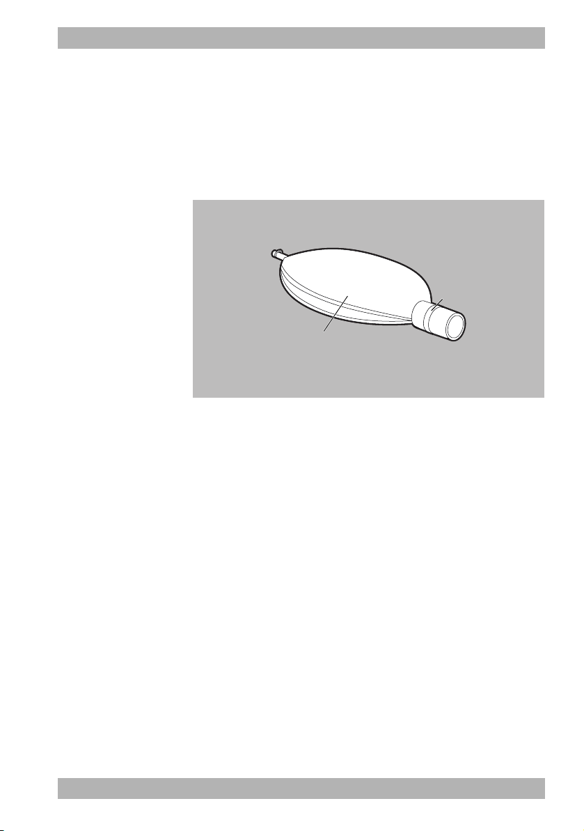
3.3.7 Testing bag
3-10 Testing bag
The testing bag (1) serves to check the functionality of the device
prior to use. During testing, the testing bag simulates the human
lung.
3 Description
The connector (2) is connected to the patient valve for the function
check.
WM 68271 05/2019
MEDUMAT Easy
CPR
EN 23
Page 24
3 Description
2
1
3
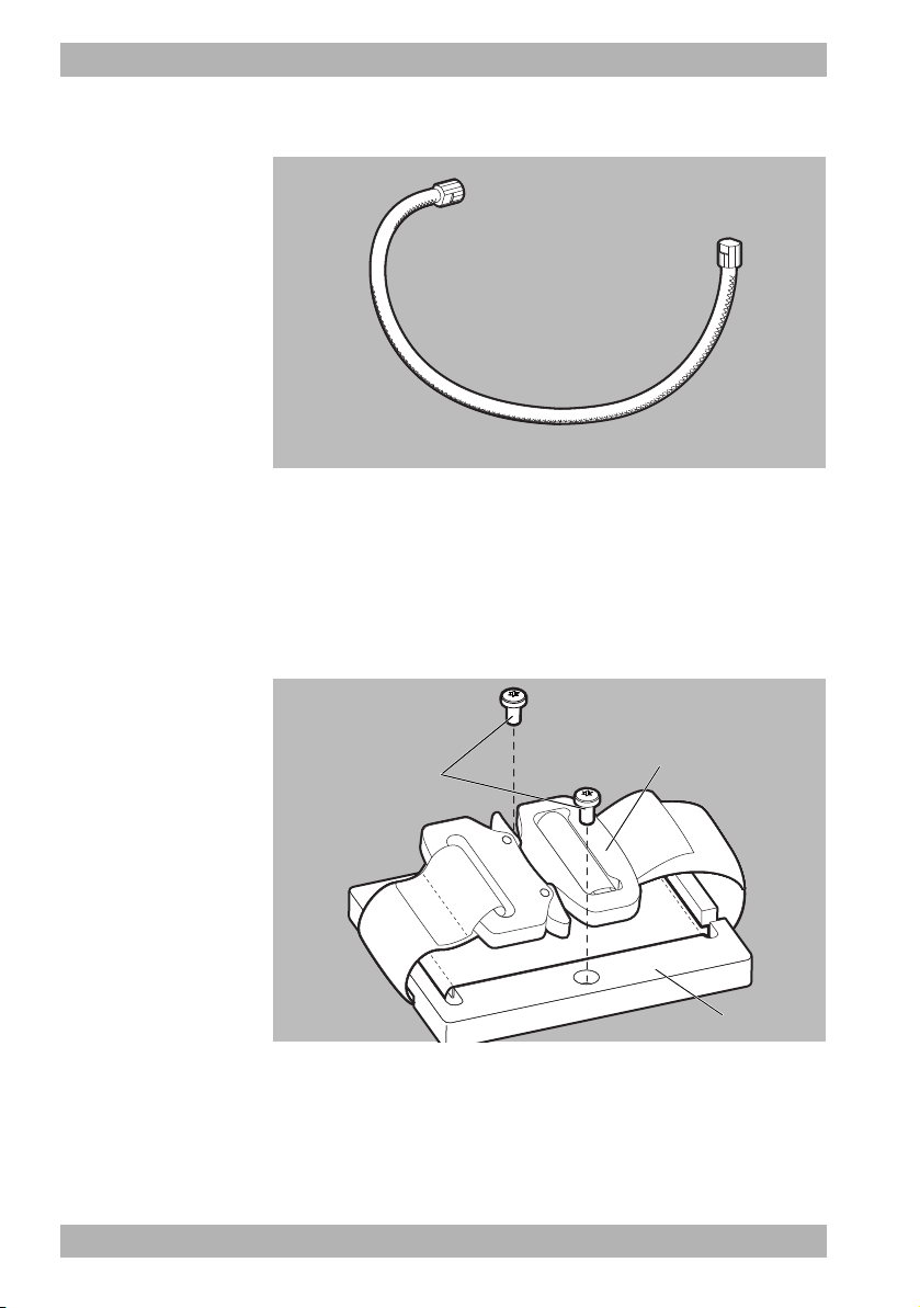
3.3.8 Compressed gas tube
3-11 Compressed gas tube
The compressed gas tube connects the device to the oxygen
supply.
3.3.9 Mounting set with mounting plate and
fastening strap
3-12 Mounting set with mounting plate and fastening strap
The mounting set serves to temporarily secure the device to the site
of use. It comprises a mounting plate (3), screws (1), and a
fastening strap with a safety lock (2).
24 EN MEDUMAT Easy
WM 68271 05/2019
CPR
Page 25
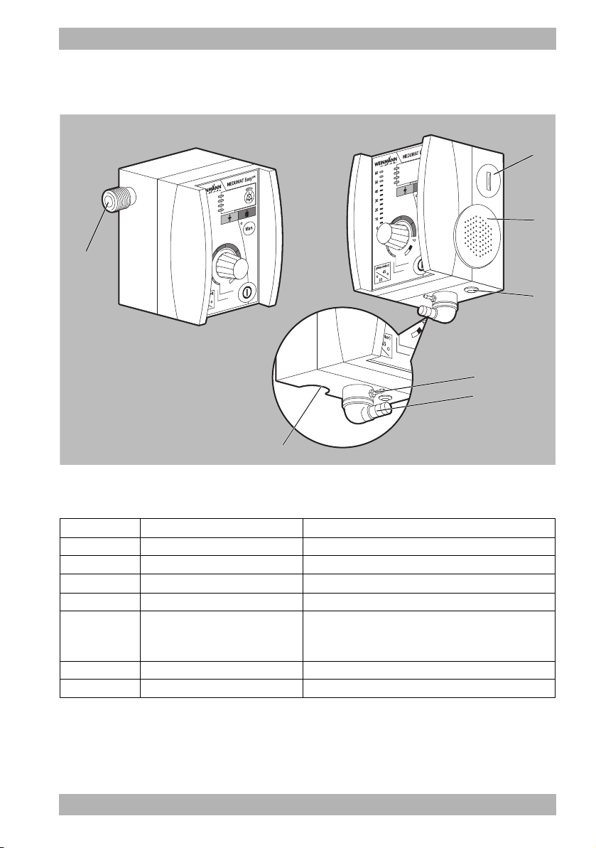
3.4 Connections and interfaces
3
4
5
7
1
2
6
3 Description
3-13 Connections and interfaces
No. Designation Description
1 Compressed gas connection Connects the oxygen supply to the device.
2 Battery compartment Houses the battery.
3 Loudspeaker Emits audible alarms.
4 Connection for MEDUtrigger Connects the MEDUtrigger to the device.
5
Connection for pressure
measuring tube
Connects the pressure measuring tube to the device.
Conducts the airway pressure at the patient valve to
the pressure sensor inside the device.
6 Connection for ventilation hose Connects the ventilation hose to the device.
7 Pressure relief valve Serves to limit the ventilation pressure.
WM 68271 05/2019
MEDUMAT Easy
CPR
EN 25
Page 26

3 Description
1
2
3
4
5
6
7
8
9
10
11
3.5 Control panel
3-14 Control panel
No. Designation Description
1 Ventilation pressure display Displays the ventilation pressure in mbar.
2 Alarm field
3 LED for alarm muting
Indicates alarm states visually.
• LED is lit: Alarm is active.
• LED is not lit: Alarm is not active.
Indicates the status of alarm muting.
• LED is lit: The alarm is muted for 120 seconds.
• LED is not lit: The alarm is switched on.
4 Alarm mute button Serves to mute the alarm and switch the audible alarm back on.
5 Color legend
Displays assignment of the ventilation parameters:
•Orange: Child
•Red: Adult
6 Man. button with control LED
Adjusting knob for the
7
ventilation parameters
26 EN MEDUMAT Easy
Activates and deactivates the manual mode (CPR mode). Shows
readiness for operation.
Serves to set the ventilation rate freq (breaths per minute) and
tidal volume Vt (ml).
CPR
WM 68271 05/2019
Page 27

No. Designation Description
1
9
2
5
4
3
8
76
10
8 Snap-in position
Switches between continuous mode and the demand flow
mode.
Visually displays the status of the demand flow mode.
9 LED demand flow
• Illuminated: The demand flow mode is switched on.
• Not illuminated: The demand flow mode is switched off.
10 On/Off button Switches the device on or off.
11 pMax button with control LEDs
Switches between the ventilation pressure limit for mask
ventilation (20 mbar) and tube ventilation (45 mbar).
3.6 Labels and symbols
3.6.1 Labels on the device
3 Description
3-15 Labels on the device
WM 68271 05/2019
MEDUMAT Easy
CPR
EN 27
Page 28

3 Description
2.7-6 bar/
40-87 psi
>40 l/min STPD
O
2
REF
SN
No. Symbol Description
1
2
2
IP54
Rx only
Input 2.7-6 bar (40-87 psi) O
2
STPD – Standard Temperature and Pressure, dry
Article number
Serial number
Protection against the ingress of dust and splash water from all
sides
Type BF applied part
Do not dispose of device in household waste
CE mark (confirms that the product complies with the applicable
European directives)
Device only available with prescription as per US legislation
[Code of Federal Regulations (CFR) Title 21]
28 EN MEDUMAT Easy
Manufacturer with date of manufacture (YYYY-MM-DD)
UDI marking - possible application identifiers:
(01): Global Trade Item Number (GTIN) – globally unique
Identification Number
(10): Batch/Lot number
(11): Date of manufacture in format YYMMDD
(17): Expiration date in format YYMMDD
(21): Serial number
WM 68271 05/2019
CPR
Page 29

No. Symbol Description
pMax
100 mbar/
<
<
1.45 psi
Follow the instructions for use
Do not sit on the device
3
Do not climb on the device
UL marking with certification label (see “13.1 Device”,
page 134)
Indicates the MEDUtrigger connection
4
Type BF applied part
3 Description
5 Opening pressure of release valve ≤ 100 mbar (1.45 psi)
Hose system connection (ventilation hose and pressure
measuring tube)
6
Type BF applied part
7 Service label: Indicates when the next maintenance is required
STK sticker (only in the Federal Republic of Germany): Indicates
8
when the next safety check in accordance with §11 of the
MPBetreibV (German regulations governing owners/operators
of medical devices) is required.
WM 68271 05/2019
MEDUMAT Easy
CPR
EN 29
Page 30

3 Description
LSH 14
Software-Version:
V. X X
1
2
No. Symbol Description
9 Indicates the battery position
10 Optional: Integrated software version
3.6.2 Labels on the MEDUtrigger
30 EN MEDUMAT Easy
3-16 Labels on the MEDUtrigger
WM 68271 05/2019
CPR
Page 31

No. Symbol Description
Protection class II, protective insulation
3 Description
1
2
IP54
Protection against the ingress of dust and splash water from all
sides
Do not dispose of device in household waste
Type BF applied part
Observe the instructions for use
CE mark (confirms that the product complies with the applicable
European directives)
Manufacturer
Pull out the plug vertically and do not turn
UDI marking - possible application identifiers:
(01): Global Trade Item Number (GTIN) – globally unique
Identification Number
(10): Batch/Lot number
(11): Date of manufacture in format YYMMDD
(17): Expiration date in format YYMMDD
(21): Serial number
WM 68271 05/2019
MEDUMAT Easy
CPR
EN 31
Page 32

3 Description
1
23
4
Patient
WM 28110REF
3.6.3 Labels on the disposable hose system with
disposable patient valve
3-17 Labels on the disposable hose system with patient valve
No. Symbol Description
1 Adhesive label with article number and flow direction arrows
2 EXHALE Direction of flow during expiration
3
4
32 EN MEDUMAT Easy
SINGLE PATIENT
USE
REF
CPR
Disposable item, do not reuse.
Article number
Disposable item, do not reuse.
Manufacturer
Batch code
WM 68271 05/2019
Page 33

3 Description
1
2
3
3.6.4 Labels on the reusable hose system with
reusable patient valve
3-18 Labels on the reusable hose system with patient valve
No. Symbol Description
1 Observe instructions for use and correct assembly.
2 Installation direction of lip membrane
3 Shows inspiration direction.
WM 68271 05/2019
MEDUMAT Easy
CPR
EN 33
Page 34

3 Description
1
3.6.5 Labels on the compressed gas tube
3-19 Labels on the compressed gas tube
No. Symbol Description
REF
1
Rx only
34 EN MEDUMAT Easy
Article number
UDI marking - possible application identifiers:
(01): Global Trade Item Number (GTIN) – globally unique
Identification Number
(10): Batch/Lot number
(11): Date of manufacture in format YYMMDD
(17): Expiration date in format YYMMDD
(21): Serial number
Manufacturer
CE mark (confirms that the product complies with the applicable
European directives)
Device only available with prescription as per US legislation
[Code of Federal Regulations (CFR) Title 21]
Batch code
WM 68271 05/2019
CPR
Page 35

3.6.6 Labels on the testing bag
1
1
3-20 Labels on the testing bag
No. Symbol Description
Manufacturer with date of manufacture (YYYY-MM-DD)
1
3 Description
REF
Article number
3.6.7 Labels on the mounting plate
3-21 Labels on the mounting plate
WM 68271 05/2019
MEDUMAT Easy
CPR
EN 35
Page 36

3 Description
REF
SN
No. Symbol Description
REF
Rx only
1
Article number
CE mark (confirms that the product complies with the applicable
European directives)
Observe the instructions for use
Device only available with prescription as per US legislation
[Code of Federal Regulations (CFR) Title 21]
Manufacturer with date of manufacture (YYYY-MM-DD)
Batch code
UDI marking - possible application identifiers:
(01): Global Trade Item Number (GTIN) – globally unique
Identification Number
(10): Batch/Lot number
(11): Date of manufacture in format YYMMDD
(17): Expiration date in format YYMMDD
(21): Serial number
3.6.8 Labels on the packaging
Symbol Description
36 EN MEDUMAT Easy
Article number
Observe the instructions for use
Serial number
WM 68271 05/2019
CPR
Page 37

Symbol Description
Batch code
CE mark (confirms that the product complies with the applicable European directives)
Manufacturer, possibly with date of manufacture (YYYY-MM-DD)
Observe the instructions for use
3 Description
Rx only
Device only available with prescription as per US legislation [Code of Federal
Regulations (CFR) Title 21]
UL marking with certification label (see “13.1 Device”, page 134)
UDI marking - possible application identifiers:
(01): Global Trade Item Number (GTIN) – globally unique Identification Number
(10): Batch/Lot number
(11): Date of manufacture in format YYMMDD
(17): Expiration date in format YYMMDD
(21): Serial number
Fragile
Important! Important safety-related information such as warnings and precautions
are included in the instructions for use. These are not stated on the label or the device
itself.
Storage temperature range limits
Storage humidity range limits
WM 68271 05/2019
MEDUMAT Easy
CPR
EN 37
Page 38

3 Description
Symbol Description
Disposable item, do not reuse
Store in a dry place
Can be used up to YYYY-MM-DD
3.7 Ventilation modes
3.7.1 Demand flow mode
In demand flow mode, the device switches to respirationcontrolled oxygen inhalation. As a result, the patient’s breathing is
supported. In demand flow mode, ventilation is performed
exclusively with the ventilation mask. Due to slight negative
pressure on the patient valve (inspiration trigger), oxygen flows
until slight excess pressure interrupts the flow and expiration is via
the patient valve.
In demand flow mode, the ventilation pressure limit is
automatically set to 20 mbar (20 cmH
As such, the device emits an information tone if the pMax button
with control LEDs is pressed in demand flow mode.
Further information on the demand flow mode can be found in the
section “Operation” (see “6.4.1 Ventilating the patient in demand
flow mode”, page 73).
38 EN MEDUMAT Easy
CPR
) and cannot be changed.
2
WM 68271 05/2019
Page 39

3.7.2 Manual mode (CPR mode)
It is possible to specify the respiratory rate oneself in manual mode.
It can only be activated when MEDUtrigger is connected.
MEDUtrigger can be used to vent manual breaths to the patient
with the adjusted tidal volume.
For example, manual mode is used to check the tube after
intubation or for cardiopulmonary resuscitation.
If the voice prompt and/or metronome function is switched on, the
device guides you through the cardiopulmonary resuscitation.
Manual mode is called CPR mode when the voice prompt is
activated.
The length of the expiration phase corresponds to the length of
inspiration phase in manual mode (CPR mode). The respiratory
time ratio is 1:1.
Further information on the manual mode (CPR mode) can be
found in the section “Operation” (see “6.4.2 Ventilating the
patient in manual mode (CPR mode)”, page 75).
3.7.3 Continuous mode (IPPV)
The continuous mode (IPPV mode) is used for mandatory volumecontrolled ventilation with a fixed minute volume. The minute
volume is set via a combined setting of the tidal volume and
frequency. This mode is used on patients who have no
spontaneous respiration. The set ventilation pressure limitation
(pMax) ensures the safety of the patient.
3 Description
Further information on the continuous mode can be found in the
section “Operation” (see “6.4.3 Ventilating the patient in
continuous mode”, page 81).
WM 68271 05/2019
MEDUMAT Easy
CPR
EN 39
Page 40

4 Preparation
4 Preparation
4.1 Unpacking the delivery and visual inspection
1. Remove the packaging material.
2. Recycle the packaging material and dispose of properly.
3. Check the delivery to ensure nothing is missing (see “12.1
Standard scope of supply”, page 132).
4. Check the device and accessories for external damage.
5. Do not operate the device in the event of damage or if
accessories are missing. Contact the Customer Service (see
“1.2 Customer Service”, page 6).
Result The delivery has been unpacked and visually checked.
4.2 Install the device on a carrying system or carrying structures
If the device is installed on a carrying system, you will require the
fastening elements set WM 15007 (see “12.1 Standard scope of
supply”, page 132).
Use screws for installation on carrying structures (M4). Pay
attention to the requisite insertion depth when selecting the
screws. The screws must insert between 6 and 7 mm into the
sockets on the rear in the installed state.
40 EN MEDUMAT Easy
WM 68271 05/2019
CPR
Page 41

4 Preparation
1. Install the device on the carrying system or carrying structures
using screws and protective disks.
2. Tighten screws.
Result The device is installed on a carrying system or carrying structures.
4.3 Securing the mounting plate with fastening strap to the device
Malfunction or failure of treatment as a result of insufficiently
secured devices!
If the device is not sufficiently secured, its uncontrolled movement
can lead to functional failure. This can result in serious or lifethreatening injury to the patient.
Always pull the fastening strap tight.
WM 68271 05/2019
MEDUMAT Easy
CPR
EN 41
Page 42

4 Preparation
1
2
1. Position the red marking of the fastening strap (1) on the red
recess on the mounting plate (2).
2. Insert the ends of the fastening strap into the depressions on
42 EN MEDUMAT Easy
the mounting plate.
WM 68271 05/2019
CPR
Page 43

4 Preparation
3. Screw the mounting plate onto the device by turning the
supplied screws clockwise.
4. Place the fastening strap around the desired piece of
equipment.
5. Close the safety lock on the fastening strap. To do so, connect
the two buckles until they securely lock into place.
6. Warning! Risk of injury due to uncontrolled
movements!
Pull the fastening strap tight.
Result The device is assembled on the equipment with the mounting plate
and fastening strap.
WM 68271 05/2019
MEDUMAT Easy
CPR
EN 43
Page 44

4 Preparation
2
3
1
4
4.4 Connecting an oxygen supply
Risk of fire and explosion due to highly compressed oxygen
combined with hydrocarbon compounds!
Hydrocarbon compounds (e.g., oil, grease, cleaning alcohol, hand
cream or adhesive plasters) can cause explosive reactions if they
come into contact with highly compressed oxygen. This can result
in severe or life-threatening injury to the patient, user or
bystanders.
Always wash hands thoroughly and remove adhesive plasters
before working with the oxygen supply.
Compromised oxygen therapy as a result of unsuitable
oxygen!
Unsuitable oxygen can compromise the treatment. This can result
in serious or life-threatening injury to the patient.
Do not operate the device with compressed gas or non-
medical oxygen
Material damage due to use of a tool!
All the screwed unions have been designed such that they can be
released by hand. The use of a wrench or other tool could damage
the device or accessories.
Do not use wrenches or other tools to tighten or release union
nuts.
1. Connect the pressure reducer (1) to the oxygen cylinder (2). To
do so, screw on the pressure reducer (1) onto the cylinder valve
(4) with the knurled union nut (3) and tighten by hand.
44 EN MEDUMAT Easy
WM 68271 05/2019
CPR
Page 45

4 Preparation
1
2
3
2. Using the union nut (2) or quick-release coupling, connect the
compressed gas hose (1) to the pressure reducer (3) or central
gas supply by hand. To this end, screw the union nut (2)
clockwise.
3. Connect the other end of the compressed gas tube to the
device using the union nut. To do this, screw the union nut
onto the device’s compressed gas connection in a clockwise
direction.
Result The oxygen supply is connected.
WM 68271 05/2019
MEDUMAT Easy
CPR
EN 45
Page 46

4 Preparation
1
2
3
4
5
6
7
8
9
10
4.5 Assemble reusable hose system
Requirement The reusable hose system is disassembled.
46 EN MEDUMAT Easy
1. If necessary: Install the reusable patient valve:
• Insert the O-ring (10) into the groove on the spontaneous
respiration insert (1) of the reusable patient valve.
• Insert disk diaphragm/emergency air membrane (2) in
spontaneous respiration side (3) of the reusable patient
valve.
• Insert spontaneous respiration insert (1) in spontaneous
respiration side (3) of the reusable patient valve.
• Insert disk diaphragm (4) in expiration side (5) of the
reusable patient valve.
• Insert flawless lip membrane (8).
When doing so, pay attention to the insertion direction
symbol on the patient valve (9).
CPR
WM 68271 05/2019
Page 47

4 Preparation
1
2
• Warning! Treatment fault due to patient valve lip
membrane installation errors!
Check the correct positioning of the lip membrane in
accordance with the installation direction symbol on the
patient valve (9).
• Screw the connection for ventilation hose (6) onto the
reusable patient valve lid (7) in a clockwise direction.
• Install the reusable patient valve lid (7) in a clockwise
direction.
2. Connect the reusable ventilation hose (1) and pressure
measuring tube (2) to the reusable patient valve.
When doing so, note: The hoses must be firmly attached to the
patient valve.
Result The reusable hose system is assembled.
WM 68271 05/2019
MEDUMAT Easy
CPR
EN 47
Page 48

4 Preparation
1
2
4.6 Connecting the patient hose system and MEDUtrigger to the device
Requirement The patient hose system has been assembled (see “4.5 Assemble
reusable hose system”, page 46).
1. Grasp the end of the pressure measuring tube (1) and push
onto the connection.
2. Grasp the end of the ventilation hose (2) and push onto the
connection. If necessary: Turn the ventilation hose (2) slightly
to avoid bending the pressure measuring tube (1).
48 EN MEDUMAT Easy
WM 68271 05/2019
CPR
Page 49

4 Preparation
3. Connect the MEDUtrigger connector to the MEDUtrigger
connection. To do this, insert the connector, without turning,
straight into the socket.
The MEDUtrigger cable points towards the front of the device.
4. Connect the MEDUtrigger cable to the patient hose system:
• With the disposable hose system: Connect the
MEDUtrigger cable to the patient hose system using the
clips.
or
• With the reusable hose system: Pull the hose protection
sleeve over the ventilation hose, pressure measuring tube,
and MEDUtrigger cable.
WM 68271 05/2019
MEDUMAT Easy
CPR
EN 49
Page 50

4 Preparation
5. CAUTION! Delayed treatment due to incorrect
position of MEDUtrigger on the patient valve!
Push MEDUtrigger fully onto the inspiration side of the patient
valve.
Result The patient hose system and MEDUtrigger are connected.
The device is now ready for the function check (see “5 Function
check”, page 51).
50 EN MEDUMAT Easy
WM 68271 05/2019
CPR
Page 51

5 Function check
5 Function check
If this function check reveals any faults or deviations from the
specified values, you must not use the MEDUMAT Easy
You should first try to rectify the fault with the aid of the
information provided in the section “Error messages” (see “9.2
Faults”, page 123). If you are unable to rectify the faults using the
table, please contact WEINMANN Emergency or a technician who
has been expressly authorized by WEINMANN Emergency
promptly.
Devices and accessories which are defective or not ready for
use can disrupt the therapy or cause it to fail completely!
The use of defective devices or accessories can cause the device to
malfunction. This can result in severe or life-threatening injury to
the patient and user.
Perform a full function check before every use.
Only use devices and accessories which have successfully
passed the function check.
5.1 Intervals for function check
Perform the function check at the following intervals:
Part concerned Interval
• Before each use
Device and accessories
• After each cleaning and disinfection
• After each disassembly
• At least every 6 months (if not used)
CPR
.
5.2 Visually checking the device and accessories
Requirement The device is switched off (see “6.6 Switching the device off”,
page 84).
1. Check the device and accessories for external damage.
WM 68271 05/2019
2. Carefully bend the MEDUtrigger cable and check for:
MEDUMAT Easy
CPR
EN 51
Page 52

5 Function check
• Damage
•Wear
•Exposed wires
• Bent connection lines
3. Check that all the connectors and connections engage
properly.
4. Check the testing bag for damage. Check the balloon and the
integrity of the connector.
• Check that the testing bag’s balloon is firmly attached to
the connector.
5. Check the patient valve, connectors, and membranes for
external damage, cracks, distortions, and soiling.
6. If necessary: Replace any damaged accessories.
7. If necessary: Dispose of any damaged accessories (see “11.3
Disposal”, page 131).
8. WARNING! Device failure due to dead batteries!
Check whether a spare battery is available.
Result The device and accessories have been checked visually.
5.3 Preparing for the function check
Required material Oxygen supply
Requirement The device and accessories have been checked visually and are in
perfect condition (see “5.2 Visually checking the device and
accessories”, page 51).
1. Connect the device to the oxygen supply (see “4.4 Connecting
an oxygen supply”, page 44).
2. Connect the patient hose system and MEDUtrigger up to the
device (see “4.6 Connecting the patient hose system and
MEDUtrigger to the device”, page 48).
3. Keep a testing bag available for subsequent steps.
Result The device is ready for the function check.
52 EN MEDUMAT Easy
CPR
WM 68271 05/2019
Page 53

5 Function check
1
5.4 Checking the system for leaks
Damage to the device due to pressure blows on fittings!
Opening the oxygen cylinder valve too quickly can lead to strong
pressure surges and damage the oxygen cylinder or the fitting.
Always open the oxygen cylinder valve slowly.
Requirement • The device is connected to the oxygen supply (see “4.4
Connecting an oxygen supply”, page 44).
• The device is switched off (see “6.6 Switching the device off”,
page 84).
1. Open the oxygen cylinder slowly.
To do this, turn the handwheel counterclockwise slowly.
2. Read off the oxygen cylinder pressure on the contents gauge
(1) of the pressure reducer.
3. Close the oxygen cylinder.
4. Monitor the needle on the contents gauge (1) on the pressure
reducer for 1 minute.
• If the position of the needle remains constant: The system
Result The system has been checked for leaks.
WM 68271 05/2019
is free from leaks.
• If the needle falls continuously: The system is not leakproof.
If the system is leaking, remedy the system leak as described below.
MEDUMAT Easy
CPR
EN 53
Page 54

5 Function check
Rectifying leaks in the system
Requirement The system is not leakproof.
1. Check that the tubes are connected correctly (see “5.2 Visually
checking the device and accessories”, page 51).
2. Check that the screw connections are tightened correctly (see
“5.2 Visually checking the device and accessories”, page 51).
3. Check the system for leaks once more (see “5.4 Checking the
system for leaks”, page 53).
4. If a leak in the system cannot be remedied, have the device
repaired (see “1.2 Customer Service”, page 6).
Result The leak in the system has been rectified.
5.5 Checking device functions
In order to perform the function check comprehensively and
rapidly, check all functions in succession in the order below.
Risk of injury from improperly removed testing bag!
If the testing bag is removed improperly, the connector of the
testing bag may remain on the patient hose system. The resulting
increase in inspiratory airway resistance can injure the patient.
When disassembling always pull the testing bag off at the
connector.
Damage to the device due to pressure blows on fittings!
Opening the oxygen cylinder valve too quickly can lead to strong
pressure surges and damage the oxygen cylinder or the fitting.
Always open the oxygen cylinder valve slowly.
The pAW alarm can be ignored when performing the following
testing steps unless testing the alarm itself is specifically required.
5.5.1 Checking visual and audio alarm output
Requirement • The device and accessories have been checked visually (see
“5.2 Visually checking the device and accessories”, page 51).
• The function check is ready (see “5.3 Preparing for the function
check”, page 52).
54 EN MEDUMAT Easy
CPR
WM 68271 05/2019
Page 55

5 Function check
1 *
2
1
3
5
4
6
• The device is switched off.
1. Open the oxygen cylinder slowly.
2. Connect the testing bag to the inspiration side of the patient
valve.
3. Switch on the device using the On/Off button.
Upon being switched on, the device performs an automatic
self-test which takes approx. 2 seconds.
4. Monitor the self-test and also check the following signals:
• Check whether the device emits an audio signal when
being switched on.
• Check that all the LEDs in the control panel light up at least
once when being switched on: Demand flow (1), pMax (2),
ventilation pressure display (3), alarm (4), alarm mute (5),
Man.(6).
WM 68271 05/2019
MEDUMAT Easy
CPR
EN 55
Page 56

5 Function check
1
2
• Check whether the bottom most LED on the ventilation
pressure display (1) lights up green.
• Check that the LED (2) for the alarm goes out and
that the device commences ventilation in the correct
manner.
5. Press the alarm mute button.
• Check that the alarm mute LED lights up.
56 EN MEDUMAT Easy
WM 68271 05/2019
CPR
Page 57

5 Function check
6. Press the alarm mute button again.
• Check that the alarm mute LED goes out.
Result The visual and audio alarm output has been checked.
5.5.2 Checking the supply pressure alarm
1. Close the oxygen cylinder.
• Check whether the <2.7barO2 alarm is triggered once
the device supply pressure falls below 2.7 bar O
2. Open the oxygen cylinder slowly.
.
2
• Check whether the <2.7bar O2 alarm is switched off once
there is sufficient supply pressure.
Result The supply pressure alarm has been checked.
5.5.3 Checking the ventilation rate
1. Select the following settings:
Via the adjusting knob: Vt = 65 ml at rate = 25 breaths per
minute
Via the pMax button with control LEDs: 45 mbar
WM 68271 05/2019
MEDUMAT Easy
CPR
EN 57
Page 58

5 Function check
1:00 min
23-27
/ min
Result The ventilation rate has been checked.
5.5.4 Checking the tidal volume and aware pressure
2. Count the number of inspiration phases for exactly 1 minute.
• Check whether the ventilation rate is between 23 and
27 breaths per minute.
In combination with the testing bag, these settings can cause the
pAW
/
Apnea alarm to be triggered. The alarm can be ignored
during this test step.
measurement
1. Select the following settings:
Via the adjusting knob: Vt = 950 ml at rate = 10 breaths per
minute
Via the pMax button with control LEDs: 45 mbar
In combination with the testing bag, these settings can cause the
pAW alarm to be triggered. The alarm can be ignored during
this test step.
58 EN MEDUMAT Easy
WM 68271 05/2019
CPR
Page 59

5 Function check
2. Simulate the expiration phase by hand with the testing bag. To
this end, place the testing bag on a firm surface and, during the
expiration phase, press on the testing bag with your hand flat
until the volume has been completely discharged via the
patient valve.
• Check whether the testing bag fills completely during
inspiration.
• Check whether the LEDs in the ventilation pressure display
light up to the 40-45 mbar range during inspiration.
The testing bag is not sufficiently filled if the pAW/Apnea alarm
is triggered.
3. Allow the device to ventilate without simulating the expiration
phase.
• Check whether the device triggers the pAW alarm after
the third inspiration breath at 40-50 mbar.
WM 68271 05/2019
MEDUMAT Easy
CPR
EN 59
Page 60

5 Function check
4. CAUTION! Risk of injury from improperly removed
testing bag!
Grasp the testing bag by the connector and pull the bag and
connector off the patient valve.
• Check whether the device triggers the pAW
/
Apnea
alarm after the second inspiration breath.
5. Connect the testing bag to the inspiration side of the patient
valve again.
Result The tidal volume and airway pressure measurement have been
checked.
60 EN MEDUMAT Easy
WM 68271 05/2019
CPR
Page 61

5.5.5 Checking the MEDUtrigger
1
1. Select the following setting:
Via the adjusting knob: Vt = 950 ml at rate = 10 breaths per
minute
Via the pMax button with control LEDs: 45 mbar
2. Press the Man. button.
• Check whether the control LED on the Man. button lights
up.
5 Function check
• Check whether both LEDs on the MEDUtrigger light up.
3. Press the button on the MEDUtrigger (1).
• Check whether a mechanical breath is triggered.
WM 68271 05/2019
MEDUMAT Easy
CPR
EN 61
Page 62

5 Function check
1
2
Result The MEDUtrigger has been checked.
5.5.6 Checking the demand flow mode
4. Exit manual mode (CPR mode). To do this, press the Man.
button again.
1. Select the “demand flow” setting. To do this, turn the
adjusting knob for ventilation parameters clockwise past the
snap-in position (1).
• Check whether the green demand flow LED (2) lights up.
62 EN MEDUMAT Easy
CPR
WM 68271 05/2019
Page 63

2. Simulate the inspiration trigger with one hand. To do this, press
the testing bag firmly together in your hand and then release
with a jerk.
• Check whether the device switches the flow on and
immediately off again. You can hear a slight click.
3. Switch off the device using the On/Off button. To do this, keep
the On/Off button depressed until all 4 alarm LEDs light up.
Then release the On/Off button.
4. CAUTION! Risk of injury from improperly removed
testing bag!
Grasp the testing bag by the connector and pull the bag and
connector off the patient valve.
5. Close the oxygen cylinder.
Result The demand flow mode has been checked.
The function check is complete.
5 Function check
WM 68271 05/2019
MEDUMAT Easy
CPR
EN 63
Page 64

6 Operation
6 Operation
6.1 Preparing for ventilation
Requirement • The device and accessories have been cleaned and disinfected
• The device is ready for use (see “4 Preparation”, page 40).
• The function check is complete (see “5 Function check”,
Failure of treatment due to insufficient oxygen capacity and/
or battery capacity!
Insufficient oxygen capacity and/or battery capacity prevents
patient ventilation. This can result in serious or life-threatening
injury to the patient.
Perform a full function check before every use.
Only start ventilation if, during the function check, the alarm
Check the oxygen cylinder pressure prior to ventilation.
Do not start ventilation if there is insufficient oxygen cylinder
Keep an alternative ventilation unit at the ready.
(see “8 Cleaning and disinfection”, page 100).
page 51).
indicating insufficient battery capacity is not emitted.
pressure.
Damage to the oxygen cylinder due to corrosion!
Moist ambient air may enter oxygen cylinders which have been
completely emptied and cause corrosion.
Do not empty oxygen cylinders completely.
Damage to the device due to pressure blows on fittings!
Opening the oxygen cylinder valve too quickly can lead to strong
pressure surges and damage the oxygen cylinder or the fitting.
Always open the oxygen cylinder valve slowly.
1. If necessary: Connect the compressed gas tube to the oxygen
cylinder or the central gas supply.
64 EN MEDUMAT Easy
WM 68271 05/2019
CPR
Page 65

6 Operation
1
2. Open the oxygen cylinder slowly.
The contents gauge (1) displays the oxygen cylinder pressure.
3. Calculate the remaining operating time to ensure that the
device does not stop unexpectedly (see “14 Appendix”,
page 141).
4. Connect accessories.
• Connect ventilation mask or tube (see “6.1.1 Connecting
the ventilation mask or tube”, page 65)
• Connect breathing system filter (see “6.1.2 Connecting the
breathing system filter”, page 67)
• Connect PEEP valve (see “6.1.3 Connecting the PEEP
valve”, page 69)
Result The device is ready for use.
6.1.1 Connecting the ventilation mask or tube
Delayed treatment due to incorrect position of MEDUtrigger
on the patient valve!
If MEDUtrigger is incorrectly connected to the patient valve, it will
WM 68271 05/2019
not be possible to properly attach the ventilation mask, which can
lead to incorrect or delayed treatment. This can injure the patient.
Push MEDUtrigger fully onto the inspiration side of the patient
valve.
MEDUMAT Easy
CPR
EN 65
Page 66

6 Operation
1
2
3
1
2
3
1. Connect the ventilation mask (1) together with MEDUtrigger
(2) on the patient valve (3).
or
66 EN MEDUMAT Easy
Connect the tube (1) together with the MEDUtrigger (2) on the
patient valve (3).
2. Check whether the MEDUtrigger has been pushed down fully
on the patient valve.
Result The ventilation mask or tube is connected.
CPR
WM 68271 05/2019
Page 67

6.1.2 Connecting the breathing system filter
Fault or treatment failure due to incompatibility of the device
with consumables, accessories or other medical devices!
Defective and unauthorized accessories can result in malfunctions,
increased electromagnetic interference emissions and reduced
electromagnetic immunity of the device, incorrect output values
and reduced ventilation performance. This can result in serious or
life-threatening injury to the patient.
Only connect approved accessories.
Hypoventilation due to the use of additional breathing system
filters!
The dead space of the overall system increases due to the use of
additional breathing system filters (breathing system filter,
bacteria filter or combined breathing system bacteria filter).
Increased dead space can result in hypoventilation. This can result
in serious or life-threatening injury to the patient.
Only use approved accessories.
Increase in the dead space with ventilation with small tidal
volumes.
Increased breathing effort due to the use of additional
accessories!
The spontaneous respiration resistance of the overall system
increases due to the use of additional accessories such as a filter
(breathing system filter, bacteria filter or combined breathing
system bacteria filter). This can injure the patient.
Only use approved accessories.
Monitor increase in spontaneous respiratory resistance for the
patient.
6 Operation
Connecting the breathing system filter for mask
ventilation
1. Observe the instructions for use from the breathing system
filter manufacturer.
WM 68271 05/2019
MEDUMAT Easy
CPR
EN 67
Page 68

6 Operation
1
2
3
4
1
2
3
4
2. Connect the breathing system filter (3) to the patient
connection of the patient valve (4).
3. Connect MEDUtrigger (2) to the breathing system filter (3).
4. Connect the ventilation mask (1) to MEDUtrigger (2).
Result The breathing system filter is ready for mask ventilation.
Connecting the breathing system filter for tube
ventilation
68 EN MEDUMAT Easy
1. Observe the instructions for use from the breathing system
filter manufacturer.
2. Connect the breathing system filter (3) to the patient
connection of the patient valve (4).
CPR
WM 68271 05/2019
Page 69

6 Operation
1
2
3. Connect MEDUtrigger (2) to the breathing system filter (3).
4. Following intubation, connect the tube (1) to the
MEDUtrigger (2).
Result The breathing system filter is ready for tube ventilation.
6.1.3 Connecting the PEEP valve
1. Observe the instructions for use from the PEEP valve
manufacturer.
2. Attach the PEEP valve (2) to the expiration side (1) of the
patient valve.
Result The PEEP valve is attached.
WM 68271 05/2019
MEDUMAT Easy
CPR
EN 69
Page 70

6 Operation
6.2 Setting the ventilation parameters
6.2.1 Setting the respiratory rate and tidal volume
1. Set the tidal volume Vt and associated respiratory rate. To do
this, turn the adjusting knob for ventilation parameters.
Result The respiratory rate and tidal volume are set.
Assignment of the ventilation parameters
Orange Red
Age (in years) approx. 1-12 from approx. 13
Body weight in kg (lbs)
Respiratory rate
(breaths per minute)
Tidal volume (ml) 65
70 EN MEDUMAT Easy
10
(22) 15(33)
25
The values given in the table are recommendations. Please note
that the values may deviate with pulmonary diseases or special
indications.
The correlation between the ventilation parameters can be found
in the section “Technical data” (see “13.5 Correlation between
ventilation parameters”, page 140).
20 15 12 10 10 10 10
100 150 300 500 600 800 950
CPR
20
(44)45(100) 75(165) 90(198)
120
(265)
140
(308)
WM 68271 05/2019
Page 71

6 Operation
6.2.2 Setting the maximum ventilation pressure
Requirement The device is switched on (see “6.3 Switching the device on”,
page 72).
1. Set the ventilation pressure. To do this, press the pMax button
with control LEDs.
The associated LED displays the set maximum ventilation
pressure.
Result The maximum ventilation pressure is set.
Recommendation for maximum ventilation pressure
Mask ventilation Tube ventilation
20 mbar (20 cmH2O) 45 mbar (45 cmH2O)
If, for example, with reduced lung compliance the set maximum
ventilation pressure is reached, the device emits the pAW alarm.
WM 68271 05/2019
MEDUMAT Easy
CPR
EN 71
Page 72

6 Operation
6.3 Switching the device on
1. Switch on the device using the On/Off button.
Upon being switched on, the device performs an automatic
self-test which takes approx. 2 seconds. During the self-test, all
the LEDs in the alarm field flash and a brief audible alarm
sounds.
2. WARNING! Risk of injury from using a defective
device!
Do not operate the device in the following cases:
• 4 alarm LEDs in the alarm field do not flash.
• LEDs in the alarm field flash uninterruptedly and an alarm
•Alarm <2.7barO
• Alarm is active.
Result The device is switched on.
72 EN MEDUMAT Easy
sounds.
being open.
CPR
is active despite the oxygen cylinder
2
WM 68271 05/2019
Page 73

6 Operation
6.4 Ventilating the patient
Impaired treatment due to increased breathing effort!
If the expiration side and/or the spontaneous respiration side is
covered, the breathing effort required of the patient increases and
impairs treatment. This can injure the patient.
Never cover the expiration side and spontaneous respiration
side of the patient valve.
6.4.1 Ventilating the patient in demand flow mode
Switching on demand flow mode
Requirement The device is ready for use (see “6.1 Preparing for ventilation”,
page 64).
Impaired treatment due to reduced trigger performance in
demand flow mode!
In demand flow mode, a PEEP valve can lead to reduced trigger
performance and can impair treatment. This can injure the
patient.
Do not use a PEEP valve in demand flow mode.
1. Switch on demand flow mode. To do this, turn the adjusting
knob for ventilation parameters clockwise past the snap-in
position.
The green LED displays the operational status.
2. Switch on the device (see “6.3 Switching the device on”,
page 72).
WM 68271 05/2019
MEDUMAT Easy
CPR
EN 73
Page 74

6 Operation
3. Place the ventilation mask on the mouth and nose. Hold the
ventilation mask firmly in place.
• With inspiration (triggering): Flow is switched on.
• At the start of expiration: Flow stops and the expiration air
is discharged via the patient valve.
4. Make sure that the patient breathes calmly and evenly.
If the device does not detect breathing within 20 seconds, the
pAW
/
Apnea alarm is triggered.
Result The device is operated in demand flow mode.
Switching off demand flow mode
1. Switch off the device (see “6.6 Switching the device off”,
page 84).
2. Turn the adjusting knob for ventilation parameters past the
snap-in position in a counterclockwise direction.
Result The demand flow mode is switched off.
74 EN MEDUMAT Easy
WM 68271 05/2019
CPR
Page 75

6 Operation
6.4.2 Ventilating the patient in manual mode
(CPR mode)
Lack of treatment due to the attempt to trigger manual
breaths in demand mode and continuous mode!
If the device is not in manual mode (CPR mode) and the
MEDUtrigger is not connected, the device/user cannot manually
trigger mechanical breaths. This can injure the patient.
For manual mechanical breaths, connect MEDUtrigger and
switch to manual mode (CPR mode).
Switching on manual mode
Requirement • The device is ready for use (see “6.1 Preparing for ventilation”,
page 64).
• MEDUtrigger is connected (see “4.6 Connecting the patient
hose system and MEDUtrigger to the device”, page 48).
• A tidal volume is set with the adjusting knob for the ventilation
parameters (see “6.2.1 Setting the respiratory rate and tidal
volume”, page 70).
• The device is switched on (see “6.3 Switching the device on”,
page 72).
• Voice prompt is deactivated (see “6.7 Activating/deactivating
the voice prompt”, page 85).
• The metronome is deactivated (see “6.8 Activating/
deactivating the metronome”, page 87).
WM 68271 05/2019
MEDUMAT Easy
CPR
EN 75
Page 76

6 Operation
1. Press the Man. button.
The LEDs on the Man. button and on the MEDUtrigger display
the operational status.
Upon activation of the manual mode, continuous ventilation
with the set frequency stops.
If the button on the MEDUtrigger is pressed and the manual mode
is not activated, an information tone sounds. This occurs, for
example, if the Man. button or the button on the MEDUtrigger is
pressed in demand flow mode.
2. If necessary: Place the ventilation mask on the mouth and nose.
Hold the ventilation mask firmly in place.
3. Press the button on MEDUtrigger to ventilate the patient:
• To trigger a single mechanical breath, press the button on
or
• To trigger two mechanical breaths one after the other,
A new mechanical breath can only be triggered if the inspiration
and expiration phase of the previous mechanical breath has
already ended.
An information tone sounds if the inspiration and expiration
phase has not yet ended.
Result The device is operated in manual mode.
76 EN MEDUMAT Easy
the MEDUtrigger once.
press and hold the button on MEDUtrigger.
WM 68271 05/2019
CPR
Page 77

6 Operation
Switching off manual mode
1. Press the Man. button.
The device continues to ventilate in continuous mode.
or
2. Activate the demand flow mode (see “6.4.1 Ventilating the
patient in demand flow mode”, page 73)
or
3. Switch off the device (see “6.6 Switching the device off”,
page 84).
Result The manual mode is switched off.
WM 68271 05/2019
MEDUMAT Easy
CPR
EN 77
Page 78

6 Operation
Switching on CPR mode
Requirement • The device is ready for use (see “6.1 Preparing for ventilation”,
page 64).
• MEDUtrigger is connected (see “4.6 Connecting the patient
hose system and MEDUtrigger to the device”, page 48).
• A tidal volume is set with the adjusting knob for the ventilation
parameters (see “6.2.1 Setting the respiratory rate and tidal
volume”, page 70).
• The device is switched on (see “6.3 Switching the device on”,
page 72).
• Voice prompt and/or the metronome is switched on (see “6.7
Activating/deactivating the voice prompt”, page 85) and (see
“6.8 Activating/deactivating the metronome”, page 87).
Risk of limited treatment due to insufficient patient
monitoring!
If the metronome is switched on, the audible alarms in CPR mode
pause during the chest compression and voice prompt phases. In
case of limited patient monitoring, this may compromise the
treatment. This can injure the patient.
Monitor patients in CPR mode continuously.
Limited patient monitoring via deactivated voice prompt for
the pAW and pAW
Voice prompt is deactivated for the pAW and pAW
alarms in CPR mode.
In case of limited patient monitoring, this may result in injuries to
the patient.
Monitor patients in CPR mode continuously.
78 EN MEDUMAT Easy
CPR
/
Apnea alarms in CPR mode!
/
Apnea
WM 68271 05/2019
Page 79

6 Operation
1. Press the Man. button.
• The LEDs on the Man. button and on the MEDUtrigger
display the operational status.
• The continuous ventilation with the set rate stops.
• The device outputs the message: CPR mode switched on,
manual triggering of ventilation.
If the metronome is switched on, the device outputs the message:
Perform chest compressions now!
2. Perform 30 chest compressions.
When doing so, note: The metronome sets the ideal frequency.
The tone pitch increases with the metronome’s last three
strikes.
The device outputs the message:
Provide 2 ventilations now!
3. Trigger two mechanical breaths:
Press and hold the button on the MEDUtrigger until two
mechanical breaths have been triggered.
or
Press the button on the MEDUtrigger twice in a row.
WM 68271 05/2019
MEDUMAT Easy
CPR
EN 79
Page 80

6 Operation
A new mechanical breath can only be triggered if the inspiration
and expiration phase of the previous mechanical breath has
already ended.
An information tone sounds if the inspiration and expiration
phase has not yet ended.
If the button on the MEDUtrigger is pressed continuously, the
device triggers an unlimited number of subsequent mechanical
breaths.
4. Perform 30 chest compressions and two mechanical breaths in
alternation.
The voice prompts and metronome are static. We recommend
adjusting to the metronome and voice prompts.
Result The device is operated in CPR mode.
Switching off CPR mode
1. Press the Man. button.
The device continues to ventilate in continuous mode.
or
2. Activate the demand flow mode (see “6.4.1 Ventilating the
patient in demand flow mode”, page 73).
or
3. Switch off the device (see “6.6 Switching the device off”,
page 84).
Result The CPR mode is switched off.
80 EN MEDUMAT Easy
WM 68271 05/2019
CPR
Page 81

6 Operation
6.4.3 Ventilating the patient in continuous mode
Switching on continuous mode
Requirement • The device is ready for use (see “6.1 Preparing for ventilation”,
page 64).
• The device is switched off (see “6.6 Switching the device off”,
page 84).
• A tidal volume and frequency are set on the adjusting knob for
ventilation parameters (see “6.2.1 Setting the respiratory rate
and tidal volume”, page 70).
• The patient is intubated.
1. Switch on the device using the On/Off button.
Result The device is operated in continuous mode.
Switching off continuous mode
1. Switch off the device (see “6.6 Switching the device off”,
page 84)
or
2. Change to manual mode (see “6.4.2 Ventilating the patient in
manual mode (CPR mode)”, page 75)
or
3. Change to demand flow mode (see “6.4.1 Ventilating the
patient in demand flow mode”, page 73).
Result The continuous mode is switched off.
WM 68271 05/2019
MEDUMAT Easy
CPR
EN 81
Page 82

6 Operation
0
10
20
30
Ventilation pressure progress before and after
the reduction in lung compliance
mbar
6.4.4 Monitoring the patient
Risk of incorrect treatment due to insufficient patient
monitoring!
If the patient and device are not supervised and monitored during
ventilation, delayed responses of medical personnel to alarms and
error messages may result in serious or life-threatening injuries to
the patient and to incorrect treatment.
The patient and device must be kept under continuous
observation and monitoring during ventilation.
Use additional external monitoring during ventilation (e.g.,
SpO
or etCO2).
2
1. Check the ventilation pressure. To do this, read off the
ventilation pressure on the ventilation pressure display.
2. Check the ventilation parameters.
3. Check the cause of the emitted alarms (see “9 Alarms and error
messages”, page 118).
High air resistances, e.g., due to obstructions of the airways or
during external chest compression, change the set tidal volume.
With reduced lung compliance, the device reacts as per the
diagram shown below by way of example, with an increase in the
ventilation pressure whilst the ventilation volume remains
constant.
82 EN MEDUMAT Easy
WM 68271 05/2019
CPR
Page 83

6.5 Muting alarms
6.5.1 Activating alarm mute function
When an alarm is emitted, you can suppress the alarm tone for a
maximum of 120 seconds. The exception to this is the supply
pressure alarm <2.7barO
be muted.
If the cause of the alarm continues to exist after 120 seconds, a
new alarm is emitted.
If the error is remedied, the visual and audible alarms are
automatically reset.
Alarm muting also applies to new alarms which are emitted within
these 120 seconds. The visual alarm is always active when in
muted state.
Requirement • The device is switched on.
• An alarm is triggered.
2
6 Operation
. The supply pressure alarm can not
1. Press the alarm mute button.
Result • The audible alarm is deactivated for 120 seconds.
• The orange LED above the alarm mute button lights up.
6.5.2 Deactivating alarm mute function
Requirement • The audible alarm is activated (see “6.5.1 Activating alarm
mute function”, page 83).
• The orange LED above the alarm mute button lights up.
WM 68271 05/2019
MEDUMAT Easy
CPR
EN 83
Page 84

6 Operation
1. Press the alarm mute button.
Result • The alarm mute function is deactivated.
• The orange LED goes out.
6.6 Switching the device off
Requirement The device is switched on.
1. Press and hold the On/Off button for approx. 3 seconds until
all 4 alarm LEDs light up.
2. Release the On/Off button.
3. Close the oxygen cylinder.
Result The device is switched off.
84 EN MEDUMAT Easy
WM 68271 05/2019
CPR
Page 85

6.7 Activating/deactivating the voice prompt
Requirement The device is switched off.
1. Press and hold the pMax button with control LEDs
continuously.
6 Operation
2. Press the On/Off button until the following LEDs light up:
Alarm mute, Man., Demand flow.
3. Release the pMax button with control LEDs.
The device is now in the language selection menu. The
ventilation pressure display shows the last selected language
setting.
WM 68271 05/2019
MEDUMAT Easy
CPR
EN 85
Page 86

6 Operation
4. To change the language setting: press the pMax button with
control LEDs repeatedly until the LED for the required language
lights up. A corresponding voice prompt in the selected
language is output.
The languages are assigned to the individual LEDs as per the
following table.
Device no. mbar Language level 1
60 Farsi
55 Thai
50 Indonesian
45 Turkish
40 Arabic Hebrew
35 Japanese Brazilian Portuguese
WM 20300
30 Chinese Spanish
25 Czech Dutch
20 Russian Italian
15 Polish French
10 English Hindi
5 German Korean
0 Voice prompt switched off Voice prompt switched off
Language level 2
(Alarm LEDs
pAW and pAW /
Apnea light up)
Not assigned
Depending on the firmware version, additional languages may be
available.
If the 60 mbar LED on the ventilation pressure display is reached,
a new cycle begins in level 2. This is indicated by the pAW and
pAW
reached, a new cycle begins at 0 mbar in level 1 and the pAW
and pAW
5. To save the language setting:
Wait 5 seconds.
or
Press the On/Off button briefly.
86 EN MEDUMAT Easy
/
Apnea alarm LEDs. Once the last language in level 2 is
/
Apnea alarm LEDs go out.
CPR
WM 68271 05/2019
Page 87

6. To switch off the voice prompt: Select the 0 mbar LED.
The device outputs the message Audio response is off! in the
last language selected.
Result Voice prompt is activated or deactivated.
6.8 Activating/deactivating the metronome
Requirement The device is switched off.
6 Operation
1. Hold and press the Man. button continuously.
2. Press the On/Off button briefly.
WM 68271 05/2019
MEDUMAT Easy
CPR
EN 87
Page 88

6 Operation
3. If the 45 mbar or 50 mbar LED lights up on the ventilation
pressure display: Release the Man. button.
The device displays the metronome’s operating status.
• 50 mbar LED lights up red: Metronome is deactivated.
• 45 mbar LED lights up green: Metronome is activated.
4. To change the metronome’s operating status: Press the Man.
button.
5. To confirm the metronome’s operating status: Press the On/Off
button.
A confirmation sounds:
• If the confirmation sounds once: Deactivated metronome is
confirmed.
• If the confirmation sounds twice: Activated metronome is
confirmed.
Result The metronome is activated or deactivated.
88 EN MEDUMAT Easy
WM 68271 05/2019
CPR
Page 89

7 Disassembly
1
3
2
7.1 Disassembling the ventilation mask and tube
Damage to the hose system or MEDUtrigger as a result of
incorrect handling!
Carelessly grasping and pulling off the patient hose system at the
wrong point can result in damage to the system.
Always grasp hose systems at the end and pull off in a straight
line.
Pull off MEDUtrigger in a straight line without twisting.
Disassembling the ventilation mask and MEDUtrigger
7 Disassembly
1. Pull the ventilation mask (1) and MEDUtrigger (2) off the
patient valve (3).
or
Pull the ventilation mask (1) and MEDUtrigger (2) off the
breathing system filter (not shown in image).
Result The ventilation mask and the MEDUtrigger are disassembled.
WM 68271 05/2019
MEDUMAT Easy
CPR
EN 89
Page 90

7 Disassembly
1
3
2
1
3
2
Disassembling the tube and MEDUtrigger
1. Pull the tube (1) and MEDUtrigger (2) off the patient valve (3).
Result The tube and the MEDUtrigger are disassembled.
7.2 Disassembling the breathing system filter
Requirement The ventilation mask or tube is disassembled (see “7.1
Disassembling the ventilation mask and tube”, page 89).
90 EN MEDUMAT Easy
Result The breathing system filter is disassembled.
1. Observe the instructions for use from the breathing system
filter manufacturer.
2. Pull the MEDUtrigger (1) and breathing system filter (2) off the
patient valve (3).
CPR
WM 68271 05/2019
Page 91

7 Disassembly
1
2
7.3 Disassembling the PEEP valve
1. Pull off the PEEP valve (2) from the expiration side (1) of the
patient valve.
Result The PEEP valve is disassembled.
7.4 Disconnecting the patient hose system and MEDUtrigger from the device
Requirement • The ventilation mask or tube and MEDUtrigger are
disassembled (see “7.1 Disassembling the ventilation mask and
tube”, page 89).
• The breathing system filter is disassembled (see “7.2
Disassembling the breathing system filter”, page 90).
• The PEEP valve is disassembled (see “7.3 Disassembling the
PEEP valve”, page 91).
Damage to the hose system or MEDUtrigger as a result of
incorrect handling!
WM 68271 05/2019
Carelessly grasping and pulling off the patient hose system at the
wrong point can result in damage to the system.
Always grasp hose systems at the end and pull off in a straight
line.
Pull off MEDUtrigger in a straight line without twisting.
MEDUMAT Easy
CPR
EN 91
Page 92

7 Disassembly
1. NOTICE! Material damage caused by twisting the
MEDUtrigger connector back and forth!
Pull the MEDUtrigger connector out of the MEDUtrigger
connection. To do this, grasp the grooved part of the
connector and pull it straight out of the socket without turning.
2. With the disposable hose system: Disconnect the MEDUtrigger
cable from the patient hose system. To do this, release the
MEDUtrigger cable from the clips.
or
With the reusable hose system: Remove the MEDUtrigger cable
from the hose protection sleeve.
92 EN MEDUMAT Easy
WM 68271 05/2019
CPR
Page 93

7 Disassembly
1
1
3. NOTICE! Material damage from pulling out the tubes
incorrectly!
Grasp the end of the ventilation hose (1) and pull out of the
ventilation hose connection on the device.
4. NOTICE! Material damage from pulling out the tubes
incorrectly!
Grasp the end of the pressure measuring tube (1) and pull out
of the pressure measuring tube connection on the device.
Result The patient hose system and MEDUtrigger are disconnected.
WM 68271 05/2019
MEDUMAT Easy
CPR
EN 93
Page 94

7 Disassembly
1
2
7.5 Disassembly of the reusable hose system
Requirement The patient hose system and MEDUtrigger are disconnected from
the device (see “7.4 Disconnecting the patient hose system and
MEDUtrigger from the device”, page 91).
1. If necessary: Remove the hose protection sleeve from the
reusable hose system.
2. NOTICE! Material damage from pulling out the tubes
incorrectly!
Remove the reusable ventilation hose (1) and pressure
measuring tube (2) from the reusable patient valve. Grasp the
hoses by their ends when pulling off.
94 EN MEDUMAT Easy
WM 68271 05/2019
CPR
Page 95

7 Disassembly
1
2
3
4
5
6
7
8
9
3. Disassembling the reusable patient valve:
• Remove the spontaneous respiration insert (1) from the
spontaneous respiration side (3) of the reusable patient
valve.
To do so, push both locking tabs out of the mount using a
small slot-head screwdriver.
• Remove the O-ring (9) from the spontaneous respiration
insert (1).
• Remove the disk diaphragm/emergency air membrane (2)
from the spontaneous respiration side (3) of the reusable
patient valve with pointed pliers.
• Remove the disk diaphragm (4) from the expiration side (5)
of the reusable patient valve with pointed pliers.
• Unscrew the connection for ventilation hose (6) from the
reusable patient valve lid (7) in a counterclockwise
direction.
• Unscrew the reusable patient valve lid (7) in a
counterclockwise direction.
WM 68271 05/2019
MEDUMAT Easy
CPR
EN 95
Page 96

7 Disassembly
1
2
3
• Remove the lip membrane (8).
Result The reusable hose system is disassembled.
7.6 Removing the oxygen supply
Requirement • The device is switched off (see “6.6 Switching the device off”,
page 84).
• The oxygen supply is closed.
1. NOTICE! Material damage due to the disconnection of a
non-ventilated system!
Switch on the device using the On/Off button.
The remaining oxygen can escape and the device is
depressurized. The compressed gas hose can only be
disconnected without tools if the contents gauge indicates
0bar (0psi) on the pressure reducer.
2. Switch off the device using the On/Off button. To do this, keep
the On/Off button depressed until all 4 alarm LEDs light up.
Then release the On/Off button.
3. NOTICE! Material damage due to the use of a tool!
Disconnect the compressed gas tube (1) from the pressure
reducer (3) or the central gas supply by hand using the union
96 EN MEDUMAT Easy
nut (2) or the quick-release coupling. To do this, turn the
knurled union nut (2) counterclockwise.
WM 68271 05/2019
CPR
Page 97

7 Disassembly
1
4. Remove the pressure reducer from the cylinder valve on the
oxygen cylinder using the knurled union nut (1). To do so, turn
the union nut counterclockwise.
Result The oxygen supply is removed.
7.7 Disconnecting the mounting plate and fastening strap from the device
Requirement • The mounting plate and fastening strap are secured to the
device(see “4.3 Securing the mounting plate with fastening
strap to the device”, page 41).
• The device is switched off (see “6.6 Switching the device off”,
page 84).
WM 68271 05/2019
MEDUMAT Easy
CPR
EN 97
Page 98

7 Disassembly
1. Hold the device securely and open the safety lock on the
fastening strap. To do so, actuate both side levers at the same
time and disconnect the buckles.
2. Remove the mounting plate. To do this, turn the screws
counterclockwise out of the device.
98 EN MEDUMAT Easy
WM 68271 05/2019
CPR
Page 99

7 Disassembly
3. Remove the ends of the fastening strap from the depressions
on the mounting plate.
Result The mounting plate and fastening strap are removed.
WM 68271 05/2019
MEDUMAT Easy
CPR
EN 99
Page 100

8 Cleaning and disinfection
8 Cleaning and disinfection
The following sections describe the activities required for cleaning
and disinfection.
If you have any queries on cleaning and disinfection, please contact
our Customer Service (see “1.2 Customer Service”, page 6).
8.1 Intervals
Perform cleaning and disinfection at the following intervals.
Part Interval
After each use At least 1x weekly
Basic device including
all accessories
8.2 Cleaning and disinfection plan
Perform cleaning and disinfection after every use as per the table
below. When doing so, please observe the following section. It
describes the requisite steps for the reprocessing in detail.
xx
For reliable reprocessing, perform the cleaning, disinfection, and
(optional) sterilization steps one after another.
100 EN MEDUMAT Easy
WM 68271 05/2019
CPR
 Loading...