

Page 1

MEDUCORE Standard
2
Monitor/Defibrillator
Instructions for Use for Devices from Software Version 1.1
Page 2

Table of Contents
3.10 Markings and symbols ................................................................. 46
Table of Contents
1 Introduction 6
1.1 Intended use ................................................................................. 6
1.2 Function ........................................................................................ 6
1.3 Operator/user qualification ............................................................ 8
1.4 Contraindications for defibrillation ................................................. 8
1.5 Side effects ................................................................................... 9
2 Safety 10
2.1 Safety information ....................................................................... 10
2.2 General instructions .................................................................... 24
2.3 Warnings in this document .......................................................... 25
3 Description 26
3.1 Overview ..................................................................................... 26
3.2 Control panel .............................................................................. 27
3.3 Display ........................................................................................ 29
3.4 Symbols on the display ................................................................ 37
3.5 Battery and battery status indicator ............................................. 39
3.6 Components ............................................................................... 41
3.7 Accessories ................................................................................. 43
3.8 Transport options ........................................................................ 45
3.9 Options ....................................................................................... 45
4 Preparation 53
4.1 Mounting the device ................................................................... 53
4.2 Connecting to a power supply ..................................................... 53
4.3 Using the rechargeable battery .................................................... 54
4.4 Connecting the trunk cable and defibrillation electrodes .............. 57
4.5 Connecting the pulse oximetry sensor .......................................... 60
4.6 Connecting the ECG cable and ECG electrodes ............................ 64
4.7 Attaching the NIBP cuff ............................................................... 68
4.8 Using the SD card ........................................................................ 73
2 EN MEDUCORE Standard
WM 68201 12/2017
2
Page 3

Table of Contents
5 Operation 76
5.1 Switching the device on ............................................................... 76
5.2 Switching the device off .............................................................. 77
5.3 Navigating in the device .............................................................. 77
5.4 Selecting the patient group .......................................................... 78
5.5 Performing defibrillation .............................................................. 80
5.6 Performing pulse oximetry monitoring .......................................... 89
5.7 Performing ECG monitoring ......................................................... 90
5.8 Performing non-invasive blood pressure measurement (NIBP) ....... 92
5.9 Using the audio alarm output ...................................................... 97
5.10 Saving the event manually in the session data set ........................ 98
5.11 Reprocessing the device after use ................................................ 99
5.12 Saving session data/status log ................................................... 100
5.13 Analyzing sessions ..................................................................... 101
5.14 Enable options .......................................................................... 101
5.15 Transferring the device configuration to another device .............. 102
5.16 Updating the software ............................................................... 103
6 Application menu 106
6.1 Navigating the application menu ............................................... 106
6.2 Menu structure .......................................................................... 107
6.3 Settings ..................................................................................... 108
WM 68201 12/2017
7 User menu 109
7.1 Navigating the user menu ......................................................... 109
7.2 Menu structure .......................................................................... 110
7.3 Settings ..................................................................................... 111
8 Operator menu 116
8.1 Navigating the operator menu ................................................... 117
8.2 AED settings ............................................................................. 118
8.3 Alarm settings ........................................................................... 122
8.4 Manual mode settings (only with Manual mode option) ............. 128
8.5 ECG settings ............................................................................. 130
8.6 SpO
settings ............................................................................ 132
2
MEDUCORE Standard
2
EN 3
Page 4

Table of Contents
10.1 Intervals .................................................................................... 148
10.2 Performing a function check ...................................................... 148
10.3 Checking the ECG cables ........................................................... 153
10.4 Checking the NIBP cuff and NIBP connecting tube ..................... 155
11.1 General instructions .................................................................. 156
11.2 Alarm messages ........................................................................ 158
11.3 Faults ........................................................................................ 165
12.1 General instructions .................................................................. 170
12.2 Intervals .................................................................................... 170
12.3 Sending in device ...................................................................... 171
8.7 NIBP settings ............................................................................ 134
8.8 System settings ......................................................................... 137
8.9 Device information .................................................................... 142
9 Hygienic reprocessing 144
9.1 General instructions .................................................................. 144
9.2 Intervals .................................................................................... 145
9.3 Hygienic reprocessing of the device ........................................... 145
10 Function check 148
11 Alarms and faults 156
12 Maintenance 170
13 Storage 172
13.1 General instructions .................................................................. 172
13.2 Storing the device ..................................................................... 172
13.3 Storing the battery .................................................................... 173
14 Disposal 174
14.1 Electronic waste ........................................................................ 174
14.2 Battery ...................................................................................... 174
15 Technical data 175
15.1 Device ....................................................................................... 175
15.2 Defibrillation electrodes ............................................................. 177
15.3 Battery ...................................................................................... 178
15.4 Power supply unit and charger .................................................. 178
4 EN MEDUCORE Standard
WM 68201 12/2017
2
Page 5

Table of Contents
15.5 CARDIObiphasic defibrillation system ......................................... 179
15.6 ECG monitoring system ............................................................. 180
15.7 ECG analysis system CARDIOlogic .............................................. 181
15.8 Pulse oximetry monitoring ......................................................... 182
15.9 Non-invasive blood pressure (NIBP) monitoring .......................... 183
15.10 Operation/data management ..................................................... 184
15.11 Alarm delay times ...................................................................... 184
15.12 Saving of session data ............................................................... 185
15.13 Electromagnetic compatibility (EMC) .......................................... 185
15.14 The CARDIObiphasic shock impulse ........................................... 187
16 Scope of supply 190
16.1 Standard product ...................................................................... 190
16.2 Options ..................................................................................... 190
16.3 Accessories ............................................................................... 191
16.4 Replacement parts ..................................................................... 193
17 Appendix 193
17.1 Warranty ................................................................................... 193
17.2 Declaration of conformity .......................................................... 194
WM 68201 12/2017
MEDUCORE Standard
2
EN 5
Page 6

1 Introduction
1 Introduction
1.1 Intended use
MEDUCORE Standard2 is a mobile external defibrillator with
monitoring functions. It is used to measure and monitor vital
parameters and for defibrillation of emergency patients.
The following monitoring and diagnostic functions are available:
• 6-lead monitoring ECG
• Pulse oximetry
• Non-invasive blood pressure measurement
The following therapy functions are available:
• Manual defibrillation
• Semi-automatic defibrillation (from age 1)
1.2 Function
The device offers the following monitoring and diagnostic
functions:
• 6-lead monitoring ECG: The electrical activity of the heart is
derived and shown on the display. This allows the user to
interpret cardiac rhythms and the heart rate. The 6-lead
monitoring ECG does this by deriving the standard (Einthoven)
limb leads (I, II, III) and augmented (Goldberger) limb leads
(aVR, aVL, aVF) and displaying them in the curve view.
6 EN MEDUCORE Standard
WM 68201 12/2017
2
Page 7

1 Introduction
• Pulse oximetry: Pulse oximetry monitoring allows continuous,
non-invasive measurement of the arterial oxygen saturation
with the aid of different pulse oximetry sensors for different
application sites. At the same time, a photo sensor in the pulse
oximetry sensor registers the percentage of oxygenated
hemoglobin in the arterial blood (SpO
) using different light
2
wavelengths. In addition, the pulse oximetry sensor registers
the pulse rate. The values for SpO
and pulse rate are shown
2
on the display numerically, the plethysmogram in the form of
a curve.
• Non-invasive blood pressure (NIBP) monitoring: NIBP
monitoring allows measurement of blood pressure on a limb in
adults, children, and infants. Safety and effectiveness have not
been proven in pregnant women. Effectiveness in neonates (up
to 28 days) has not been proven for arrhythmias.
Measurement is based on oscillometric blood pressure
measurement technology. Following performance of the
measurement, the systolic and diastolic blood pressures in
mmHg are shown numerically on the display.
The device offers the following therapy functions:
• Manual defibrillation: Based on the information of the
displayed ECG, the user decides whether it is necessary to
administer a shock. If a shock is necessary, the user can select
the shock energy, charge the device for shock delivery, and
deliver the shock manually.
WM 68201 12/2017
• Semi-automatic defibrillation (for patients aged 1 and
upwards): In the AED mode, the device guides the user through
resuscitation by means of audio and visual instructions. The
device determines the resuscitation sequence. The device
automatically performs an ECG analysis and, if necessary,
charges for electric shock delivery. The shock is administered
manually by the user.
MEDUCORE Standard
2
EN 7
Page 8

1 Introduction
1.3 Operator/user qualification
MEDUCORE Standard2 must only be used by persons who can
verify that they have the following qualifications:
• Medical qualification, including training in cardiac life support
• Training in advanced methods of treating emergency patients
using the manual mode (see "5.5.2 Manual defibrillation (only
with Manual defibrillation option)", page 86).
As the operator or user, you must be fully familiar with the
operation of this medical device. Follow the statutory requirements
for operation and use (in Germany, particularly the German
regulations governing owners/operators of medical devices
(Medizinprodukte-Betreiberverordnung)). General
recommendation: You should seek instruction on the correct
handling, use and operation of this medical device from a person
authorized by WEINMANN Emergency.
1.4 Contraindications for defibrillation
Defibrillation must only be performed in cases of:
• Ventricular fibrillation (VF)
• Pulseless ventricular tachycardia (VT)
Contraindications include:
• The patient is responsive
• The patient is breathing normally
• ECG is showing asystole
8 EN MEDUCORE Standard
WM 68201 12/2017
2
Page 9

1.5 Side effects
Possible side-effects of defibrillation are:
• Burns
• Arrhythmias triggered by defibrillation
• Ventricular fibrillation
• Failure of active implants
• Skin irritations
• Failure of external diagnostic or therapy devices
1 Introduction
WM 68201 12/2017
MEDUCORE Standard
2
EN 9
Page 10

2 Safety
2 Safety
2.1 Safety information
2.1.1 Qualification
Warning Risk of injury due to lack of knowledge and failure to follow
Read these Instructions for Use carefully. They form part of the
devices described, and must be available at all times.
Only use the device for the intended use (see "1.1 Intended use",
page 6).
For your own safety and that of your patients, and in accordance
with the requirements of Directive 93/42/EEC, please observe the
following safety instructions.
guidelines!
The use of the device by users without medical qualifications and
training in defibrillation and/or the failure to follow guidelines can
result in injury to the patient, user or bystanders.
⇒ Only use the device if the user has a medical qualification and
is familiar with defibrillation and the operation of the device.
⇒ Follow the defibrillation guidelines.
⇒ Observe national and regional provisions and organizational
defibrillation guidelines.
2.1.2 How to use the device
Warning Risk of injury if the device is used in damp or electrically
conductive surroundings!
Using the device in damp or electrically conductive surroundings
may result in an electric shock and injury to the patient, user or
bystanders.
⇒ Only use the device in a dry place.
⇒ Only use the device in surroundings that are not electrically
conductive.
⇒ Keep conductive parts of the electrodes and plugs away from
other conductive parts and the ground.
10 EN MEDUCORE Standard
WM 68201 12/2017
2
Page 11

WM 68201 12/2017
2 Safety
Risk of injury due to device or component malfunction!
A damaged device or damaged components may result in injury
to the patient, user or bystanders.
⇒ Only operate the device and components if they are externally
undamaged.
⇒ Only operate the device and components if the function check
has been successfully completed.
⇒ Do not leave device and patient unsupervised.
⇒ In the event of device failure during resuscitation: Perform
cardiopulmonary resuscitation in line with the applicable
resuscitation guidelines and obtain a replacement device.
⇒ In the event of device failure during monitoring: Monitor
patient by monitoring breathing and taking pulse and obtain a
replacement device if required.
Risk of injury due to concealed alarm!
A concealed alarm light, loudspeaker and/or display will prevent
the user from noticing any alarms and reacting to dangerous
situations. This may result in injury to the patient.
⇒ Always keep the alarm (alarm light, loudspeaker and display)
free.
⇒ Do not operate the device in a closed bag if the alarms are then
concealed.
Risk of injury due to inaccessible device!
During use, the device requires the intervention of the user. An
inaccessible device may delay treatment and result in injury to the
patient.
⇒ Keep the device accessible at all times.
⇒ Position the device so that display and alarms are clearly visible
during use.
Risk of injury due to alarm limits which are too high or too
low!
Alarm limits which are either too high or too low can prevent the
device from emitting an alarm, thereby putting the patient at risk.
⇒ Always set alarm limits which have been adapted to the
patient.
Risk of injury due to incorrectly set parameters or too few/too
many enabled functions in the operator menu!
Incorrectly set parameters or too few/too many enabled functions
in the operator menu can result in incorrect settings in the user
menu or too limited/too comprehensive device functions. This can
cause critical operating situations and injure the patient.
MEDUCORE Standard
2
EN 11
Page 12

2 Safety
⇒ The operator menu should only be used by operators who are
familiar with the settings in the operator menu and their
impacts on the user menu and device functions. Otherwise use
the device with factory settings.
⇒ Adapt the device functions to the user’s know-how.
⇒ Protect the operator menu with a password.
Risk of injury from operating the device, accessories and
components outside of the prescribed ambient conditions!
Use of the device, accessories and components outside of the
prescribed ambient conditions may mean that tolerances are not
adhered to and result in device failure and injury to the patient.
⇒ Only operate the device within the prescribed ambient
conditions (see "15 Technical data", page 175).
⇒ Allow the device, components and accessories to acclimatize to
the operating temperature.
Risk of injury due to reuse of disposable items!
Disposable items are intended for single use. Disposable items
which are reused may be contaminated and/or impaired in their
function and therefore cause injury to the patient.
⇒ Do not reuse disposable items.
Risk of injury from using third-party accessories!
Accessories which have not been approved by
WEINMANN Emergency can result in electric shocks, incorrect
monitoring, negative impact on interference immunity and
emission or lead to damage to the device and injure the patient.
⇒ Only use accessories which have been approved by
WEINMANN Emergency.
Delay in treatment due to overly loud audio outputs!
When the defibrillator is used in conjunction with devices with
audio outputs (e.g. audible alarms, voice prompts), overly loud
audio outputs from one device can drown out the audio outputs
from the other device, and thus delay treatment.
⇒ When using multiple devices with audio outputs at the same
time, set the volume on the devices to the same level.
Risk of injury and treatment delay due to imperceptible alarm
signals!
Alarm signals which are quieter than the ambient noise level
prevent alarm situations from being detected. This can result in
treatment delays and thus to injury to the patient.
⇒ Always set the device volume to be louder than the ambient
noise level.
WM 68201 12/2017
12 EN MEDUCORE Standard
2
Page 13

WM 68201 12/2017
2 Safety
⇒ Do not stack devices.
Notice Damage to the device caused by ingress of liquids!
The device is only protected from water jets as per IP55 when the
battery is inserted and the water jet protection of the SD card slot
is closed. Ingress of liquids and dust may damage the device,
components, and accessories.
⇒ Do not immerse the device, components, or accessories in
liquids.
⇒ Only operate the device with the battery inserted.
⇒ Always close the water jet protection of the SD card slot.
2.1.3 Power supply
Warning Risk of injury due to electric shock when the device is opened!
The device has a capacitor for shock energy. Opening the device
may result in electric shock and injure people.
⇒ Do not open the device.
⇒ The device should only be opened by WEINMANN Emergency
or persons authorized by WEINMANN Emergency.
⇒ Measures such as repairs and maintenance should only be
carried out by the manufacturer or by a technician expressly
authorized by the latter.
Risk of injury due to electric shock when connecting an
incorrect power supply unit and charger to the line power!
The power supply unit and charger contains a safety device to
prevent electric shock. The use of an unsuitable power supply unit
and charger may result in injury to the user.
⇒ Only operate the device on line power using the power supply
unit and charger recommended by WEINMANN Emergency.
Risk of injury due to ECG filter not being correctly adapted to
the regional supply system!
An ECG filter which is not correctly adapted to the regional power
supply network can impair the ECG display and cause the device
to recommend a shock at the wrong point in time. This may result
in serious injury to the patient.
⇒ Adapt the ECG filter to the regional power supply network.
Risk of injury due to missing, discharged, or defective battery!
A missing, discharged or defective battery prevents treatment
functions.
⇒ Perform a function check before each use in order to check the
battery.
MEDUCORE Standard
2
EN 13
Page 14

2 Safety
⇒ Always have a charged, ready-to-use spare battery on hand.
Caution Risk of injury from touching the contacts in the battery
compartment and the patient at the same time!
The contacts in the battery compartment are live. Touching the
contacts and the patient at the same time can injure the user or
the patient.
⇒ Do not touch the contacts in the battery compartment and the
patient at the same time.
Risk of injury due to trailing power cord!
A trailing power cord is a trip hazard, which may cause injury and
hinder operation of the device being used.
⇒ During line operation, position the power cord so that it does
not present a hindrance.
⇒ During 12 V operation, position the power cord so that it does
not present a hindrance.
Risk of injury due to inaccessible power plug!
An obstructed power plug cannot be pulled out in an emergency
and can thus result in injury.
⇒ Keep the power plug and line power accessible at all times.
Notice Damage to the device caused by removal of the battery
during shock delivery!
Removal of the battery during shock delivery can cause damage to
the device.
⇒ Always leave the battery in the device while the device is
delivering a shock.
Material damage due to prolonged storage of the battery
without recharging!
Storing the battery for a prolonged period of time without
recharging can result in the rapid shutdown of and irreparable
damage to the battery.
⇒ When the battery is stored in the device without a power
supply: Charge battery every 3 months (see "13.3 Storing the
battery", page 173).
⇒ If the battery is not stored in the device: Charge battery every
5 months (see "13.3 Storing the battery", page 173).
14 EN MEDUCORE Standard
WM 68201 12/2017
2
Page 15

2 Safety
2.1.4 Defibrillation
Warning Risk of injury due to sparks during defibrillation in the
presence of oxygen and combustible materials!
During defibrillation in an oxygen-enriched atmosphere and in the
presence of combustible materials (e.g. textiles), sparks generated
by defibrillation may cause explosion and fire, which may result in
injury to the patient, user or bystanders.
⇒ When treating patients with oxygen masks, nasal tubes or
nasal cannulas: Switch off the oxygen supply or place the
inhalation points at least 1 m away from the patient during
defibrillation, and ensure that the oxygen/air mixture flows
away from the torso.
⇒ When treating patients with a resuscitator: Leave the
resuscitator securely in place on the patient tube or place it at
least 1 m away from the patient, and ensure that the oxygen/
air mixture flows away from the torso.
⇒ When connecting patients to a ventilator: Ensure that the
oxygen/air mixture coming from the exhalation valve flows
away from the torso.
⇒ When performing defibrillation in tight spaces with an oxygen-
enriched atmosphere, ensure that there is adequate
ventilation.
Risk of injury due to missing battery in the AED mode and in
manual mode!
Without a battery, the capacitor for shock energy in the device
cannot charge. This prevents defibrillation and delays treatment.
⇒ Insert a battery when using the AED mode or manual mode.
⇒ When using the AED mode or manual mode: Do not remove
the battery.
Risk of injury due to sparks during defibrillation in the
presence of flammable gases!
During defibrillation in the presence of flammable gases, sparks
may cause explosion, which may result in injury to the patient,
user or bystanders.
⇒ Do not use the device in the presence of flammable gases.
Risk of injury due to incorrect operation of the device!
Performing defibrillation on patients who are responding
normally, breathing normally or have a non-defibrillatable cardiac
rhythm will result in injury to the patient.
WM 68201 12/2017
MEDUCORE Standard
2
EN 15
Page 16

2 Safety
⇒ Only perform defibrillation on patients who are not responding
normally, are not breathing normally and have a defibrillatable
cardiac rhythm.
Risk of injury due to unsuitable AED analysis algorithm in
children below one year of age!
The device's AED analysis algorithm is not designed for children
below one year of age and may result in injury to the child.
⇒ Do not use the AED mode on children below one year of age.
Risk of injury during resuscitation due to incorrect settings in
the operator menu!
Incorrect settings in the operator menu can result in undesirable
effects during resuscitation as well as injury to the patient.
⇒ Only allow persons with specialist knowledge of the latest
resuscitation recommendations to make settings in the
operator menu.
⇒ If you are unaware of the most recent recommendations for
resuscitation: Use the factory settings.
Delay in treatment due to movement artifacts during ECG
analysis!
Movement artifacts distort the ECG. They may result in the user or
the device incorrectly interpreting the ECG, and delay treatment.
During cardiac rhythm analysis:
⇒ Place the patient in a resting position.
⇒ Stand clear of the patient.
⇒ Do not resuscitate the patient.
⇒ Do not ventilate the patient.
⇒ Do not transport the patient.
Risk of injury due to incorrectly selected size of defibrillation
electrodes!
If the wrong size of defibrillation electrodes is selected, this can
result in sub-optimal defibrillation results or in burns.
⇒ Select the correct size of defibrillation electrodes pursuant to
the resuscitation guidelines and not based on the weight
specifications given on the packaging.
Risk of injury and delay in treatment due to incorrectly placed
defibrillation electrodes!
Incorrectly placed defibrillation electrodes may distort the ECG
and result in the user delivering an unnecessary shock, not
delivering a necessary shock or unsuccessful defibrillation on the
basis of the interpretation of an incorrect ECG.
16 EN MEDUCORE Standard
WM 68201 12/2017
2
Page 17

2 Safety
⇒ Place the defibrillation electrodes correctly as per the
Instructions for Use.
⇒ Always place defibrillation electrodes together on only one
person.
⇒ Prevent the defibrillation electrodes from being touched.
⇒ Keep the defibrillation electrodes away from other electrodes
and parts in contact with the patient.
Risk of injury due to air/moisture between defibrillation
electrodes and the patient's skin!
Air (e.g. in hirsute patients) or moisture between the defibrillation
electrodes and the patient's skin prevent correct shock delivery
and may result in burns to the skin and unsuccessful defibrillation.
⇒ Remove hair in hir
sute patients.
⇒ Rub the patient's skin dry.
⇒ Firmly press on the defibrillation electrodes.
Risk of injury due to non-functional defibrillation electrodes!
Non-functional defibrillation electrodes may result in injury and
unsuccessful defibrillation.
⇒ Only use defibrillation electrodes with undamaged packaging.
⇒ Do not use defibrillation electrodes with a dry gel layer,
damage or detached protective film.
⇒ Replace damaged defibrillation electrodes.
⇒ Observe the expiry date of the defibrillation electrodes and, if
necessary, replace the defibrillation electrodes.
⇒ Dispose of defibrillation electrodes after use, and do not reuse
them.
⇒ Only use defibrillation electrodes approved by
WEINMANN Emergency for the device.
WM 68201 12/2017
Risk of injury and delay in treatment due to implanted cardiac
pacemakers!
Impulses from implanted cardiac pacemakers may affect the
detection of defibrillatable cardiac rhythms, and delay treatment.
Performing defibrillation on patients with implanted cardiac
pacemakers may irreversibly damage the myocardium.
⇒ Position defibrillation electrodes at least 8 cm away from
cardiac pacemakers.
⇒ Choose alternative positions (e.g. anterior-lateral, anterior-
posterior) for the defibrillation electrodes.
MEDUCORE Standard
2
EN 17
Page 18

2 Safety
Risk of injury due to ECG misinterpretation if ECG is derived
from the defibrillation electrodes!
If the ECG is derived from the defibrillation electrodes, the device
shows a non-diagnostic ECG curve. The ECG curve is designed to
detect shockable cardiac rhythms and is not suitable for
differential diagnostics. This can result in ECG misinterpretation,
and thus in injury to the patient.
⇒ Do not use ECGs derived from defibrillation electrodes for
differential diagnosis.
Delay in treatment due to simultaneous voice prompts from
defibrillator and ventilator!
If the defibrillator in AED mode is used in conjunction with a
ventilator (MEDUMAT Easy CPR) which also guides the user
through cardiopulmonary resuscitation by means of voice
prompts, the simultaneous voice prompts from defibrillator and
ventilator may confuse the user, and delay treatment.
⇒ When using the defibrillator in AED mode and a ventilator at
the same time, switch off the ventilator voice prompts.
Risk of injury and treatment delay from connecting the device
to several patients!
Connection of the device to several patients may result in the ECG
being misinterpreted and thus to unsuccessful defibrillation. This
can injure the patient.
⇒ Only connect the device, components and accessories to one
patient.
Notice Damage to the device caused by the delivery of defibrillation
energy!
The charging and delivery of defibrillation energy may interfere
with the functioning of other electrical devices or damage devices
connected to the patient or in the vicinity of the defibrillator.
⇒ Disconnect from the patient any electrical devices without
defibrillation protection.
⇒ After using the defibrillator, check the function of the electrical
devices in its vicinity.
⇒ Maintain separation distances between the defibrillator and
portable and mobile radio-frequency communications devices.
Damage to the device caused by removal of the defibrillation
electrodes during shock delivery!
Removal of the defibrillation electrodes during shock delivery can
cause damage to the device.
18 EN MEDUCORE Standard
WM 68201 12/2017
2
Page 19

⇒ Always leave defibrillation electrodes connected to the device
during shock delivery.
2.1.5 ECG monitoring
Warning Risk of injury from incorrect, expired or damaged ECG
electrodes!
Incorrect, expired or damaged ECG electrodes impair the quality
of the ECG signal and falsify measurements. This can injure the
patient.
⇒ Use ECG electrodes WM 45201 which have been approved by
WEINMANN Emergency. If this is not possible: Only use ECG
electrodes which satisfy all the of the following points.
⇒ Only use ECG electrodes as per AAMI EC 12.
⇒ Only use high-quality ECG electrodes.
⇒ Observe the expiry date of the ECG electrodes and, if necessary,
replace the ECG electrodes.
⇒ Only use ECG electrodes with undamaged packaging.
⇒ Do not use ECG electrodes with a dry gel layer, damage or
detached protective film.
⇒ Do not remove ECG electrodes from the packaging until
directly before use.
⇒ Replace damaged ECG electrodes during use.
⇒ Do not use ECG electrodes for defibrillation.
⇒ Dispose of ECG electrodes after use, and do not reuse them.
Risk of injury from using the 6-lead ECG for more in-depth
diagnostics!
The ECG curve of the 6-lead ECG is not suitable for differential
diagnostics (e.g. infarction diagnostics). This can result in ECG
misinterpretation, and thus in injury to the patient.
⇒ Do not use the 6-lead ECG for differential diagnostics.
⇒ Additionally, use a 12-lead diagnostics ECG device for
differential diagnostics.
Risk of injury and delay in treatment due to implanted cardiac
pacemakers!
In the case of patients with cardiac pacemakers, the device detects
the pacemaker impulses and suppresses the heart rate display and
heart rate alarms. This may result in injury to the patient.
⇒ Monitor patients with pacemakers very closely.
2 Safety
WM 68201 12/2017
MEDUCORE Standard
2
EN 19
Page 20

2 Safety
Caution Risk of injury due to ECG malfunction in the vicinity of
electrosurgical devices!
ECG functions may be affected by electrosurgical devices and
result in injury to the patient.
⇒ Only use approved ECG cables.
Risk of injury from burns during defibrillation!
ECG cables without defibrillation protection may result in injury to
the patient.
⇒ Only use approved ECG cables.
2.1.6 Pulse oximetry monitoring
Caution Risk of injury due to overly high pulse oximetry sensor contact
pressure!
High pulse oximetry sensor contact pressure over an extended
period of time can cause poor circulation or changes to the skin
and injury to the patient.
⇒ Do not attach the pulse oximetry sensor too tightly.
⇒ Check the pulse oximetry sensor every 4 hours and, if
necessary, reposition it.
⇒ Reposition the pulse oximetry sensor in the case of skin
changes.
Risk of injury from using the pulse oximetry sensor at high
temperatures!
At temperatures of > 41°C, the skin can be damaged from high
contact pressures causing injury to the patient.
⇒ Do not apply excessive pressure when attaching the pulse
oximetry sensor.
⇒ If necessary: Shorten the application time of the pulse oximetry
sensor.
Risk of injury due to incorrect use of the pulse oximetry
sensor!
The incorrect use of the pulse oximetry sensor may produce false
readings, and result in injury to the patient.
⇒ Keep the pulse oximetry sensor away from strong
electromagnetic sources (e.g. electrosurgical devices).
⇒ Do not use the pulse oximetry sensor in radiological areas
(e.g. with MRI devices).
⇒ Keep the pulse oximetry sensor away from strong and
fluctuating ambient light (including infrared and UV light). If
necessary: cover.
WM 68201 12/2017
20 EN MEDUCORE Standard
2
Page 21

2 Safety
⇒ Avoid strong movement of the pulse oximetry sensor. If
necessary: To relieve strain, loop the pulse oximetry sensor
cable and the pulse oximetry sensor connecting cable and fix to
the patient with a plaster.
⇒ Do not attach the pulse oximetry sensor to a limb on which
there is already an NIBP sleeve or catheter port.
⇒ Keep the pulse oximetry sensor away from nail polish and
artificial fingernails.
⇒ Keep the pulse oximetry sensor away from intravascular dyes.
⇒ Beware inaccurate readings in the case of elevated levels of
dysfunctional hemoglobins.
⇒ Note deviations from the measurement result in the case of
serious anemia, venous pulsation and high total bilirubin
values.
⇒ Note deviations from the pulse rate with an intra-aortic balloon
pump or certain arrhythmias.
If necessary: Compare the pulse rate with the heart rate
determined by ECG monitoring.
⇒ Note deviations from the measurement result during
defibrillation.
⇒ Only use undamaged pulse oximetry sensors.
⇒ Only use the pulse oximetry sensors and pulse oximetry sensor
connecting cables contained in the scope of supply and
mentioned in the accessories.
WM 68201 12/2017
2.1.7 Non-invasive blood pressure (NIBP) monitoring
Warning Risk of injury due to incorrect NIBP cuff!
An incorrectly selected or used NIBP cuff can lead to patient
injuries.
⇒ Attach the NIBP cuff so that the blood supply is not stopped.
⇒ Do not attach the NIBP cuff to a limb with an intravenous
infusion.
⇒ Do not attach the NIBP cuff to a limb with a shunt.
⇒ Do not attach the NIBP cuff to a limb with open wounds or
burns.
⇒ In the case of patients who have undergone a mastectomy, do
not attach the NIBP cuff to the affected side. In the case of
patients who have undergone double mastectomies, attach
the NIBP cuff to the non-dominant arm.
⇒ Do not attach the NIBP cuff to a limb with poor circulation.
MEDUCORE Standard
2
EN 21
Page 22

2 Safety
Caution Risk of injury from falsified measurement results during non-
invasive blood pressure monitoring!
An incorrectly selected or used NIBP cuff can falsify the results and
lead to patient injuries.
⇒ Always use the NIBP cuff which is best suited to the patient’s
limb. Selecting the right NIBP cuff is vital to ensuring goodquality results.
⇒ Attach the NIBP cuff level with the heart.
⇒ Avoid moving the NIBP cuff during NIBP measurements.
⇒ Do not bend or crush the NIBP cuff and the NIBP connecting
tube.
⇒ Repeat the NIBP measurement if the results appear
questionable. If the results of the repeated measurement are
still questionable, select an alternative method.
⇒ Do not attach the NIBP cuff to a limb on which there is already
a pulse oximetry sensor or another monitoring device.
⇒ Only use undamaged NIBP cuffs.
⇒ Only use the NIBP cuffs and NIBP connecting tubes contained
in the scope of supply and mentioned in the accessories.
⇒ Follow the Instructions for Use for the NIBP cuff
Risk of injury from overly frequent measurements
Overly frequent measurements can lead to circulation problems
and patient injury.
⇒ Select the measurement intervals so that sufficient perfusion is
guaranteed.
⇒ With long-lasting NIBP measurements, check the position of
the NIBP cuff regularly and, if necessary, reposition it
2.1.8 Electromagnetic compatibility
Warning Risk of injury from mutual influence of medical electrical
devices!
Medical electrical devices which are operated directly next to or on
top of each other can cause mutual interference to functionality
and thus patient injury.
⇒ Do not stack the device with other medical electrical devices.
⇒ Do not operate the device in the direct vicinity of other medical
electrical devices (exception: Approved combinations of
devices for MEDUCORE Standard
from WEINMANN Emergency).
22 EN MEDUCORE Standard
2
on the portable systems
WM 68201 12/2017
2
Page 23

2 Safety
⇒ If stacking or operation in the immediate vicinity cannot be
avoided: Closely monitor the functioning of all affected
medical electrical devices and do not use if functions are
disrupted.
Risk of injury from increased interference emissions or
reduced interference immunity!
Electronic accessories such as cables, sensors and power supply
units and chargers influence electromagnetic interference
emissions and immunity and can lead to malfunctioning of the
device or other medical electrical devices. This can injure the
patient.
⇒ Only use the articles defined by WEINMANN Emergency in the
scope of supply and accessories.
Risk of injury from portable radio-frequency communication
devices in the immediate vicinity of the device!
Portable radio-frequency communication devices (e.g. mobile
radios, antennae and antenna cables) in the direct vicinity of the
device can influence the functioning of the device and injure the
patient.
⇒ With portable radio-frequency communication devices,
maintain a minimum distance of 30 cm to the device,
components and accessories.
WM 68201 12/2017
Caution Delay in treatment due to interference caused by
electromagnetic fields!
Electromagnetic fields can impair the functioning of the device.
This can lead to incorrect analysis results, false measurements and
false alarms and thus delay treatment.
⇒ Maintain separation distances (see "15 Technical data", page
175).
Delay in treatment due to power supply network faults!
Transient or pulsed conducted interferences may cause the device
to malfunction. This can lead to false measurements and false
alarms and thus delay treatment.
⇒ If there is major interference in the power supply network, only
operate the device with a battery.
MEDUCORE Standard
2
EN 23
Page 24

2 Safety
2.2 General instructions
• If third-party items are used, malfunctions may occur and
fitness for use may be restricted. Biocompatibility requirements
may also not be met. Please note that in such cases, any
warranty claim and liability will be voided if neither the
accessories recommended in the Instructions for Use nor
original replacement parts are used. Third-party items may
increase the radiation output or reduce the interference
immunity.
• Repairs, servicing and maintenance should only be carried out
by the manufacturer WEINMANN Emergency or by a
technician expressly authorized by the latter.
• The manufacturer, WEINMANN Emergency, guarantees the
compatibility of the device and all components or accessories
connected to the patient prior to use. Only have modifications
to the device (exception: software update) carried out by the
manufacturer, WEINMANN Emergency, or by a technician
expressly authorized by the latter. Do not use any articles from
third parties.
• Any constructive changes made to the device may put the
patient and the user at risk and are not permitted.
• The power supply unit and charger is not intended for use in
vehicles or outdoors. Only use the power supply unit and
charger in closed rooms and observe the technical data (see
"15 Technical data", page 175).
• Please observe the section on hygienic reprocessing in order to
avoid infection or bacterial contamination (see "9 Hygienic
reprocessing", page 144).
• Also follow the respective Instructions for Use for the
components and the accessories.
• Always carry out a function check before using the device (see
"10 Function check", page 148).
• Risks due to software errors have been minimized by means of
extensive qualification measures.
24 EN MEDUCORE Standard
WM 68201 12/2017
2
Page 25

• This device’s software contains code which is subject to the
General Public License (GPL). You will receive the source code
and the GPL upon request.
2.3 Warnings in this document
Warnings are used to flag up safety-relevant information.
You will find a warning preceding any action that entails a hazard
for persons or equipment.
Warnings consist of
• the warning symbol (pictogram),
• a signal word designating the hazard level,
• information about the hazard, and
• instructions for avoiding the hazard.
The warnings appear in three hazard levels depending on the
degree of danger:
Danger!
Designates an extremely dangerous situation. Failure to observe
this warning may lead to serious,
irreversible injury or death.
2 Safety
WM 68201 12/2017
Warning!
Designates an extremely dangerous situation. Failure to observe
this warning may lead to serious, irreversible or fatal injury.
Caution!
Designates a dangerous situation. Failure to observe this warning
may lead to minor or moderately serious injury.
Note!
Indicates a harmful situation. Failure to observe this warning may
lead to damage to equipment.
Designates useful information relating to a particular action.
MEDUCORE Standard
2
EN 25
Page 26

3 Description
13
10 928
11
76
45
3 Description
3.1 Overview
3-1 Device
No. Designation Description
1 ECG connection for ECG cable Connects the device to the ECG cable.
2 Display
3 Alarm light Indicates high-priority alarms visually.
4 Power supply connection Connects the device to the power supply.
5 Security seal
6 Loudspeaker
7 SD card slot For inserting an SD card.
8 Pad connection for trunk cable
port for pulse oximetry sensor
SpO
9
26 EN MEDUCORE Standard
2
connecting cable
Displays settings and current values (see "3.4 Symbols
on the display", page 37).
Indicates whether the device has been opened without
authorization.
Emits audible voice prompts, alarms and heart rate
tones/pulse tones.
Connects the device via the trunk cable to the
defibrillation electrodes and the function test resistor.
Connects the device to the pulse oximetry sensor via
the pulse oximetry sensor connecting cable.
2
WM 68201 12/2017
Page 27

No. Designation Description
1
2
3
7
5
6
12
10
11
8
9
4
10 Connection for NIBP connecting tube
Connects the device to an NIBP cuff via the NIBP
connecting tube.
11 Battery compartment with battery Houses the battery.
3.2 Control panel
3 Description
3-2 Controls
No. Designation Description
1 Line power indicator Indicates that the device is connected to line power.
• Steady green light: The battery is full or is not
being charged because it is outside the charging
2 Battery status indicator
temperature range.
• Flashing green light: The battery is being charged.
• Steady red light: The battery is defective or not in
the device.
• No light: The device is not connected to line
power.
3 Shock button Delivers an electric shock for defibrillation.
4 Shock standby indicator
WM 68201 12/2017
Flashing red light when the device is ready to deliver a
shock.
MEDUCORE Standard
2
EN 27
Page 28

3 Description
No. Designation Description
• Pauses the audio alarm output for a certain length
of time.
5 Alarm button
• Mutes the audio alarm output.
• Cancels audio alarm outputs.
• Deactivates muting of the audio alarm output and
alarm cancellation.
• In the start menu: Provides access to the operator
6 Menu button
menu.
• In a mode: Provides access to the user menu.
• Allows values to be selected (by turning).
7 Navigation knob
• Confirms selected values (by pressing).
• In a mode: Provides access to the application
menu (by pressing).
8 On/Off button Switches the device on or off.
• Provide access to the mode shown on the display.
9 Function buttons
• Activate/deactivate the functions shown on the
display.
• Activates the NIBP function mode (press NIBP
10 NIBP button
button < 2 s)
• Starts an NIBP measurement (press NIBP button
for >2s)
11 Event button Manually saves an event in the data set.
Switches between the following views:
12 View button
• Parameter view
• Curve view
28 EN MEDUCORE Standard
WM 68201 12/2017
2
Page 29

3.3 Display
12
4
5
6
3
3.3.1 Start menu
3-3 Start menu display
3 Description
No. Designation Description
1 Battery status Displays the charge level of the battery.
2 Time Displays the time.
3 Service reminder (if activated) Displayed when the service interval is ≤ 30 days.
4 Patient groups
5 Function check Provides access to the function check.
6 SD card indicator Indicates the status of the SD card.
WM 68201 12/2017
Starts the device with the presets specific to the
patient groups.
MEDUCORE Standard
2
EN 29
Page 30

3 Description
123 45 7
8
9
13612 11
19
17
16
15
10
14
20
21
18
3.3.2 AED mode
3-4 Display in AED mode: Parameter view (top) and curve view
(bottom)
No. Designation Description
1 Battery status Displays the charge level of the battery.
2 Time Displays the time.
3 Session duration Displays the duration of the current session.
4 Number of shocks delivered
Displays the number of shocks delivered during the
current session.
5 Shock energy Shows the selected shock energy for the next shock.
30 EN MEDUCORE Standard
2
WM 68201 12/2017
Page 31

No. Designation Description
Shows the selected patient group:
6 Patient group
• for adults
•Child
7 Mode indicator Indicates the currently selected mode.
8 Alarm limits Displays the set alarm limits.
9 Alarm off indicator
10 AED instructions
Shows whether the alarm output is deactivated in AED
mode.
Give instructions on performing cardiopulmonary
resuscitation.
Switches the metronome algorithm between two
settings:
11 Metronome switch
• 15:2 /30:2:
15/30 chest compressions with 2 mechanical
breaths
• Intub.: Continuous chest compression
12 Monitor mode Provides access to the monitor mode.
13
14 ECG calibration mark
Manual mode (only with Manual
defibrillation option)
Provides access to the manual mode.
Shows the curve corresponding to 1 mV of the ECG
signal.
15 NIBP Shows blood pressure.
16 Pulse Shows the pulse rate.
17 SpO
2
Shows the oxygen saturation.
18 Middle curve field Shows the plethysmogram.
19 HR Shows the heart rate.
20 Top curve field Displays the ECG lead (pad, II).
21 SD card indicator Indicates the status of the SD card.
3 Description
WM 68201 12/2017
MEDUCORE Standard
2
EN 31
Page 32

3 Description
12 345 78 9
24
15 14 13
18
16
23
22
21
19
20
10
11
12
6
17
3.3.3 Manual mode
3-5 Display in manual mode
No. Designation Description
1 Battery status Displays the charge level of the battery.
2 Time Displays the time.
3 Session duration Displays the duration of the current session.
4 Elapsed time since last defibrillation
5 Number of shocks delivered
6 Shock energy Shows the selected shock energy for the next shock.
7 Alarm indicator
8 Patient group
9 Mode indicator Indicates the currently selected mode.
10 Top curve field Shows the ECG lead (Pad, II).
11 Middle curve field Displays selected ECG lead (I, II, III, aVR, aVL or aVF).
12 Bottom curve field Shows the plethysmogram.
13 Energy Allows the shock energy to be set.
32 EN MEDUCORE Standard
Displays the elapsed device time since the last
defibrillation.
Displays the number of shocks delivered during the
current session.
Indicates the status of the audio alarm output:
• Audio alarm output active
• Audio alarm output muted/paused
• Audio alarm output canceled
Shows the selected patient group:
• for adults
•Child
•Infant
2
WM 68201 12/2017
Page 33

No. Designation Description
Enables the user to select the type of ECG lead
14 ECG lead selection
displayed in the middle curve field (I, II, III, aVR, aVL
or aVF).
15 Monitor mode Provides access to the monitor mode.
16 Charging Charges the defibrillation capacitor.
17 ECG calibration mark
Shows the curve corresponding to 1 mV of the ECG
signal.
18 AED mode Provides access to the AED mode.
19 NIBP Shows blood pressure.
20 Alarm limits Displays the set alarm limits.
21 Pulse Shows the pulse rate.
22 SpO
2
Shows the oxygen saturation.
23 HR Shows the heart rate.
24 SD card indicator Indicates the status of the SD card.
3 Description
WM 68201 12/2017
MEDUCORE Standard
2
EN 33
Page 34

3 Description
12
28
45 6
7
3
25
17
16
14 12
11
13
9
8
23
26
24
22
21
20
19
18
27
10
15
3.3.4 Monitor mode
3-6 Display in monitor mode: Parameter view (top) and curve
No. Designation Description
1 Battery status Displays the charge level of the battery.
view (bottom)
2 Time Displays the time.
Indicates the status of the audio alarm output:
4 Alarm indicator
34 EN MEDUCORE Standard
• Audio alarm output active
• Audio alarm output muted/paused
• Audio alarm output canceled
2
WM 68201 12/2017
Page 35

3 Description
No. Designation Description
Shows the selected patient group:
5 Patient group
• for adults
•Child
•Infant
6 Mode indicator Indicates the currently selected mode.
7 Alarm limits Displays the set alarm limits.
8 History
Shows the time and values of the last NIBP
measurements.
9 Top curve field Shows the ECG lead (Pad, II).
10 Middle curve field Displays selected ECG lead (I, II, III, aVR, aVL or aVF).
11 Bottom curve field Shows the plethysmogram.
12 Heart rate tone/pulse tone Switches the heart rate tone/pulse tone on and off.
Enables the user to select the type of ECG lead
13 ECG lead selection
displayed in the middle curve field (I, II, III, aVR, aVL
or aVF).
14 ECG lead Displays selected ECG lead (I, II, III, aVR, aVL or aVF).
15
16 ECG calibration mark
Manual mode (only with Manual
defibrillation option)
Provides access to the manual mode.
Shows the curve corresponding to 1 mV of the ECG
signal.
17 AED mode Provides access to the AED mode.
18 NIBP Shows blood pressure.
19 Pulse Shows the pulse rate.
20 SpO
2
Displays the SpO2 curve (plethysmogram).
21 HR Shows the heart rate.
22 Duration of venous stasis
Shows the time during which the NIBP cuff maintains
a venous stasis.
Shows the time between two consecutive NIBP
23 Interval duration
measurements when measurements are taken at
intervals.
24 Initial NIBP cuff pressure
25 Alarm limits
26 SYS
27 DIA
Shows the pressure to which the device initially
inflates the NIBP cuff.
Shows the alarm limits for the systolic and diastolic
measured values.
Shows the systolic value following an NIBP
measurement.
Shows the diastolic value following an NIBP
measurement.
28 SD card indicator Indicates the status of the SD card.
WM 68201 12/2017
MEDUCORE Standard
2
EN 35
Page 36

3 Description
1
23456
7
8
9
10
11
3.3.5 NIBP function mode
3-7 Display in monitor mode with superimposed NIBP function
mode
No. Designation Description
1 History
2 Start/stop
3 iv Starts venous stasis.
4 Duration of venous stasis
5 Interval
6 Interval duration
7 Initial Allows the initial NIBP cuff pressure to be changed.
8 Initial NIBP cuff pressure
Shows the time and values of the last three NIBP
measurements.
• Starts or stops an NIBP measurement.
• Starts or stops an interval measurement.
• Stops venous stasis.
Shows the time during which the NIBP cuff maintains
a venous stasis.
• Specifies whether the NIBP measurement is an
individual NIBP measurement or an interval
measurement.
• Specifies the time between two consecutive NIBP
measurements when measurements are taken at
intervals.
Shows the time between two consecutive NIBP
measurements when measurements are taken at
intervals.
Shows the pressure to which the device will inflate the
NIBP cuff at the next NIBP measurement.
WM 68201 12/2017
36 EN MEDUCORE Standard
2
Page 37

3 Description
No. Designation Description
9 Alarm limits
10 SYS Shows the systolic value with an NIBP measurement.
11 DIA Shows the diastolic value with an NIBP measurement.
Shows the alarm limits for the systolic and diastolic
measured values.
3.4 Symbols on the display
Symbol Designation Description
Battery status symbol Battery status
SD card in SD card slot
• No SD card in SD card slot
SD card symbol
• SD card defective/not formated
•SD card full
Saving data to SD card
WM 68201 12/2017
Alarm symbol
Patient group symbol
Audio alarm output active
Audio alarm output canceled
Audio alarm output paused for the time set in
the operator menu
Audio alarm output muted with no time limit
Alarm output deactivated in AED mode
Infant patient group
Child patient group
Adult patient group
MEDUCORE Standard
2
EN 37
Page 38

3 Description
Symbol Designation Description
Heart rate tone/pulse tone
function button
Function check symbols
Cardiac symbol
Signal bar
Heart rate tone/pulse tone on
Heart rate tone/pulse tone off
Requirements for function check met
Requirements for function check not met
Fault found during function check
Follow Instructions for Use
Service interval exceeded
• In the HR parameter field: Flashes at the
measured heart rate.
• In the SpO
parameter field: Flashes at the
2
measured pulse rate.
Shows the signal quality of the SpO
2
measurement.
38 EN MEDUCORE Standard
WM 68201 12/2017
2
Page 39

3.5 Battery and battery status indicator
12 3 4
3-8 Battery and battery status indicator
No. Designation Description
1 Battery Supplies power to the device.
2 Fault indicator (red) Lights up if the battery is defective.
3 Status LEDs (green) Show the battery status.
4 Status button Activated by pressing the status LEDs.
3 Description
Status indicator on
the battery
WM 68201 12/2017
Status indicator on
the device display
Meaning
Battery status > 90%
Battery status approx. 60 %-90 %
Battery status approx. 40 %-60 %
Battery status approx. 10%-40%
MEDUCORE Standard
2
EN 39
Page 40

3 Description
Status indicator on
the battery
Status indicator on
the device display
Meaning
Battery status < 10%
On the display:
• The last remaining segment in the battery status
symbol is red.
• The message Battery weak appears in the
display.
• The device outputs in AED mode: Battery weak.
Battery is deeply discharged. Charge battery in the
device for 24 hours. After 24 hours:
• Green LED is lit: Battery fully charged and ready
for use
• Red LED or no LED is lit: Battery defective. Replace
battery.
Battery is empty
Battery empty appears on the display and the
device outputs in AED mode:
Battery empty.
The device can still be used for approx. 15 minutes.
Battery is defective. Replace battery.
• Battery is defective.
or
• No battery.
or
• Battery not at suitable temperature.
40 EN MEDUCORE Standard
Green arrow: Battery is charging
WM 68201 12/2017
2
Page 41

3.6 Components
14325
6
7
8
9
10
12
11
3 Description
3-9 Components
No. Designation Description
1
SoftTip® pulse oximetry sensor, size M,
reusable
Measures oxygen saturation.
2 Pulse oximetry sensor connecting cable Connects the pulse oximetry sensor to the device.
3 SpO
connector
2
4 ECG electrodes for adults and children Derive the electrocardiograms.
5 ECG connector
Connects the pulse oximetry sensor to the device via
the pulse oximetry connecting cable.
Connects the ECG electrodes to the device via the
ECG cable.
6 ECG cable Conducts the electrocardiograms to the device.
Conduct the electrocardiograms to the device and the
defibrillation energy to the patient.
Connects the defibrillation electrodes to the trunk
cable.
MEDUCORE Standard
2
EN 41
7 Defibrillation electrodes for adults
8 Pad connector
WM 68201 12/2017
Page 42

3 Description
No. Designation Description
9 Trunk cable
Connects the defibrillation electrodes and the
function test resistor to the device.
10 SD card Records session data.
11 NIBP connecting tube Connects the NIBP cuff to the device.
12
NIBP cuff, adult, for 23-33 cm upper arm
circumference, reusable
For measuring patient’s blood pressure.
42 EN MEDUCORE Standard
WM 68201 12/2017
2
Page 43

3.7 Accessories
1 2
12
3
4
5
9
6
8
7
10
11
3 Description
WM 68201 12/2017
3-10 Accessories
MEDUCORE Standard
2
EN 43
Page 44

3 Description
No. Designation Description
1 Charging station for battery WM 45045 Allows external battery charging.
2 Protective transport bag
Protects the device against damage and facilitates
transportation.
Conducts the electrocardiograms to the device.
3 ECG cable
Available in various designs (see "16.3 Accessories",
page 191).
4 DEFIview PC software Facilitates the read-out and analysis of session data.
5
6 Disposable pulse oximetry sensor
7 NIBP cuff
8 SoftTip
Adapter tube for connection of NIBP
disposable cuffs for neonates
®
pulse oximetry sensor, reusable
Connects the NIBP cuffs for neonates (disposable).
Measures oxygen saturation. Available in various sizes
(see "16.3 Accessories", page 191)
Measures blood pressure. Available in various
versions and sizes (see "16.3 Accessories", page 191)
Measures oxygen saturation. Available in various sizes
(see "16.3 Accessories", page 191)
9 Ear-clip pulse oximetry sensor, reusable Measures oxygen saturation.
10 Wrap pulse oximetry sensor, reusable Measures oxygen saturation.
11 Power supply unit and charger
Supplies the device or the charging station with
power.
12 Defibrillation electrodes for children Allow the defibrillation of children.
44 EN MEDUCORE Standard
WM 68201 12/2017
2
Page 45
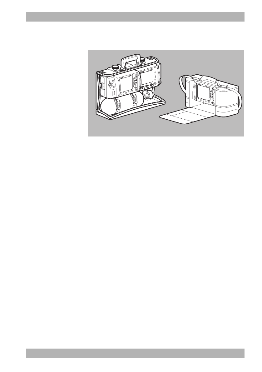
3.8 Transport options
3-11 Transport options (examples)
In order to transport the device, carry accessories, provide a
charging voltage and attach to a wall mounting, you can mount
the device on one of the following portable systems:
• LIFE-BASE 3 NG
• LIFE BASE 1 NG XL
3 Description
WM 68201 12/2017
• LIFE BASE 1 NG XS
• Protective transport bag (cannot be attached to the wall mounting)
3.9 Options
You can tailor the range of functions on the device to your needs
with the optional functions. You need a release code to enable the
optional functions. This device-specific code can be used to enable
the options (see "5.14 Enable options", page 101).
Available options:
• Manual defibrillation
MEDUCORE Standard
2
EN 45
Page 46

3 Description
54136
9
7
8
2
10
SN
3.10 Markings and symbols
3.10.1 Markings on the device
3-12 Markings on the product
No. Symbol Description
Device information label
1
= 200 J Maximum energy generated
E
max
46 EN MEDUCORE Standard
Serial number
Input (12 V-15 V, 30 W)
Direct voltage
Do not dispose of device in household waste
Type of protection against electric shock: Protection class II device
2
WM 68201 12/2017
Page 47

No. Symbol Description
Date of manufacture
Degree of protection against
IP55
1
• Ingress of solid objects
• Ingress of dust
• Ingress of water with harmful effect
Follow Instructions for Use
CE mark (confirms that the product complies with the applicable European
directives)
Other labels and symbols
Safety check label (only in the Federal Republic of Germany): Indicates when
2
the next safety check in accordance with §11 of the MedizinprodukteBetreiberverordnung [German regulations governing owners/operators of
medical devices] is required.
Metrological check label (only in the Federal Republic of Germany): Indicates
3
M
when the next metrological check in accordance with §14 of the
Medizinprodukte-Betreiberverordnung [German regulations governing
owners/operators of medical devices] is required.
4 Follow Instructions for Use
3 Description
5 Follow Instructions for Use
6 Input voltage (12 V-15 V)
Pad Connection for trunk cable
7
SpO
8
Defibrillation-proof Type BF applied part
Connection for pulse oximetry sensor
2
Defibrillation-proof Type BF applied part
9 Defibrillation-proof Type BF applied part
ECG Connection for ECG cable
10
WM 68201 12/2017
Defibrillation-proof Type CF applied part
MEDUCORE Standard
2
EN 47
Page 48

3 Description
3
1
76 54
2
3.10.2 Markings on the battery
3-13 Markings on the battery
No. Symbol Description
1 Battery fault, if fault indicator light is red
2 Battery status
3
7
4 Manufacturer
Follow Instructions for Use
5 Do not dispose of in household waste.
6
48 EN MEDUCORE Standard
China RoHS label (confirms that the product does not emit toxic substances
for the number of years indicated)
2
WM 68201 12/2017
Page 49

3.10.3 Markings on the pulse oximetry sensors
Symbol Description
Follow Instructions for Use
Do not dispose of in household waste.
Manufacturer
3.10.4 Markings on the ECG cable
Symbol Description
Follow Instructions for Use
Do not dispose of in household waste.
3 Description
WM 68201 12/2017
3.10.5 Markings on the defibrillation electrodes
Follow the Instructions for Use for the defibrillation electrodes.
3.10.6 Markings on the NIBP cuffs
Follow the Instructions for Use for the NIBP cuffs.
MEDUCORE Standard
2
EN 49
Page 50

3 Description
15
SN
3.10.7 Markings on the packaging
Symbol Description
Device packaging
REF
4
SN
Battery packaging
REF
Article number
Permissible storage temperature: -40 °C to +70 °C
Permissible storage humidity: 15 % to 95 % relative humidity
Keep dry
Fragile
Follow Instructions for Use
Serial number
CE mark (confirms that the product complies with the applicable European directives)
Manufacturer
Article number
Permissible storage temperature: -30 °C to +70 °C
Keep dry
Permissible storage humidity: Max. 95 % relative humidity
Serial number
Manufacturer
50 EN MEDUCORE Standard
WM 68201 12/2017
2
Page 51

Symbol Description
SN
sensor packaging
SpO
2
Do not dispose of in household waste.
Non-sterile
Latex-free
Permissible storage humidity: Max. 95 % relative humidity
Permissible storage temperature: -40 °C to +70 °C
IPX7 Degree of protection against temporary immersion in water
IPX2
Degree of protection against water dripping at an angle, 15° relative to the normal
operating position
Serial number
3 Description
WM 68201 12/2017
REF
Article number
CE mark (confirms that the product complies with the applicable European directives)
Date of manufacture
Manufacturer
Disposable item, do not reuse
Follow Instructions for Use
Expiration date
Production batch number
MEDUCORE Standard
2
EN 51
Page 52

3 Description
SN
Symbol Description
ECG cable packaging
4
REF
NIBP cuff packaging
Follow the Instructions for Use for the NIBP cuffs.
Defibrillation electrode packaging
Follow the Instructions for Use for the defibrillation electrodes.
ECG electrode packaging
Follow the Instructions for Use for the ECG electrodes.
Permissible storage temperature: -40 °C to +70 °C
Permissible storage humidity: Max. 95 % relative humidity
Do not dispose of in household waste
Article number
Serial number
Follow Instructions for Use
Manufacturer
Date of manufacture
52 EN MEDUCORE Standard
WM 68201 12/2017
2
Page 53

4 Preparation
4.1 Mounting the device
The device is mounted on a portable system as standard and is
ready for use. Follow the Instructions for Use for the portable
systems.
4.2 Connecting to a power supply
Risk of injury due to missing battery!
During line operation, defibrillation is not possible without the
battery. Line operation without the battery impairs the operational
readiness of the device.
⇒ Only operate the device with the battery inserted.
Damage to the device caused by ingress of liquids!
The device is only protected from water jets as per IP55 when the
battery is inserted, the water jet protection for the SD card slot is
closed and the lines for the ECG, SpO
connecting tube including NIBP cuff are connected. Ingress of
liquids and dust may damage the device, components, and
accessories.
⇒ Do not immerse the device, components, or accessories in
liquids.
⇒ Only operate the device with the battery inserted.
⇒ Always close the water jet protection of the SD card slot.
⇒ Always leave the lines for ECG, SpO
connecting tube including NIBP cuff connected.
4 Preparation
, trunk cable and NIBP
2
, trunk cable and NIBP
2
WM 68201 12/2017
1. Check battery status (see "3.5 Battery and battery status
indicator", page 39).
2. If necessary: Charge battery (see "4.3.2 Charging the battery
in the device", page 55).
MEDUCORE Standard
2
EN 53
Page 54

4 Preparation
3. Slide the fully charged battery into the battery compartment
until it clicks into place.
4. If necessary:
If operating on the portable system, mount the portable system
on a wall mounting with charging interface
or
Connect the device with its power supply unit and charger to
the line power.
or
Connect the device to a vehicle electrical system with a 12 V
cable.
Result The power supply is connected.
The power supply unit and charger is not intended for use in
vehicles or outdoors. Only use the power supply unit and charger
in closed rooms and observe the technical data (see "15 Technical
data", page 175).
4.3 Using the rechargeable battery
4.3.1 General instructions
• Always operate the device with the rechargeable battery
WM 45045.
54 EN MEDUCORE Standard
WM 68201 12/2017
2
Page 55

4 Preparation
• Note the methods of storing the battery and the charging
intervals for prolonged storage (see "13.3 Storing the battery",
page 173).
• The expected life of the battery is 2 years. Recommendation:
Replace the battery after 2 years. If battery life has substantially
dropped before then, replace the battery earlier.
• If you receive a replacement battery, you need to fully charge
it before the first use.
4.3.2 Charging the battery in the device
Requirement • The portable system is mounted on a wall mounting with
charging interface.
or
• The device is connected to the line power via the power supply
unit and charger or via the 12 V network.
1. Insert battery into the battery compartment.
When doing so, please note:
• Charging starts automatically if the following conditions
are met:
WM 68201 12/2017
Specification Description
External voltage At least 11 V
Battery status <95% charged
Battery temperature Between 0 °C and 45 °C
• If the device is switched on, the green arrow appears in the
battery status symbol on the display (example: )
and the battery status indicator on the device flashes green.
• If the device is switched off, only the battery status
indicator flashes green.
• The device remains fully ready for use.
If the battery is deeply discharged and you charge it in the device,
the battery status indicator will light up red for a short period of
time. It goes out again when the battery status progresses.
MEDUCORE Standard
2
EN 55
Page 56

4 Preparation
2. When the battery status indicator lights up green and/or the
symbol appears on the display: Disconnect the
device from the charging interface or from the power supply
unit and charger.
Result The battery is fully charged.
4.3.3 Charging the battery with the charging station
You can also charge the battery with the charging station
WM 45190. Follow the Instructions for Use for the charging
station.
4.3.4 Changing the battery
Requirement The replacement battery is fully charged.
1. If the device is not connected to the line power: Switch off the
device (see "5.2 Switching the device off", page 77).
2. Take battery out of the battery compartment.
3. Slide the replacement battery into the battery compartment
until it audibly clicks into place.
4. If necessary: Switch on the device (see "5.1 Switching the
device on", page 76).
The symbol appears on the display.
Result The battery is changed.
56 EN MEDUCORE Standard
WM 68201 12/2017
2
Page 57

4 Preparation
4.4 Connecting the trunk cable and defibrillation electrodes
Damage to the device caused by ingress of liquids!
The device is only protected from water jets as per IP55 when the
battery is inserted, the water jet protection for the SD card slot is
closed and the lines for the ECG, SpO
connecting tube including NIBP cuff are connected. Ingress of
liquids and dust may damage the device, components, and
accessories.
⇒ Do not immerse the device, components, or accessories in
liquids.
⇒ Only operate the device with the battery inserted.
⇒ Always close the water jet protection of the SD card slot.
⇒ Always leave the lines for ECG, SpO
connecting tube including NIBP cuff connected.
The following section describes how to attach the defibrillation
electrodes to the device and to the patient's torso. The
specifications in the Instructions for Use provided by the
manufacturer of the defibrillation electrodes and the information
on the packaging of the defibrillation electrodes are decisive for
the use of the defibrillation electrodes. Observe these Instructions
for Use and packaging information.
, trunk cable and NIBP
2
, trunk cable and NIBP
2
WM 68201 12/2017
1. Plug the connector of the trunk cable into the pad connection
on the device.
MEDUCORE Standard
2
EN 57
Page 58
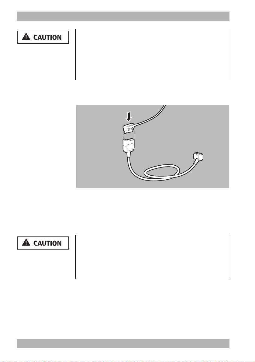
4 Preparation
Risk of injury due to incorrectly selected size of defibrillation
electrodes!
If the wrong size of defibrillation electrodes is selected, this can
result in sub-optimal defibrillation results and patient burns.
⇒ Select the correct size of defibrillation electrodes pursuant to
the resuscitation guidelines and not based on the weight
specifications given on the packaging.
2. Select suitable adult (Adult) or child (Pediatric) defibrillation
electrodes.
3. Attach the pad connector of the defibrillation electrodes to the
trunk cable.
When doing so, please note: The pad connector must be fully
inserted.
4. Bare the patient's torso.
Risk of injury from incorrect positioning of the defibrillation
electrodes!
Incorrect positioning of the defibrillation electrodes leads to a suboptimal defibrillation result.
⇒ Select the electrode position according to the illustration.
⇒ Maintain distance from ECG electrodes.
58 EN MEDUCORE Standard
WM 68201 12/2017
2
Page 59

4 Preparation
12
5. Select the required electrode position on the patient's torso:
• Position 1: Sternum-apex
• Position 2: Anterior-posterior (can also be used for adults)
Risk of injury due to air/moisture between defibrillation
electrodes and the patient's skin!
Air (e.g. in hirsute patients) or moisture between the defibrillation
electrodes and the patient's skin prevent correct shock delivery
and may result in burns to the skin and unsuccessful defibrillation.
⇒ Remove hair in hirsute patients.
⇒ Rub the patient's skin dry.
⇒ Firmly press on the defibrillation electrodes.
⇒ Wipe down oily skin with an alcohol pad.
6. If necessary: Remove hair from the torso.
7. If necessary: Rub damp spots on the torso dry.
8. If necessary: Wipe down oily skin with an alcohol pad.
9. Tear open the defibrillation electrode packaging and take out
the defibrillation electrodes.
10. Remove the protective backing from the defibrillation
electrodes.
11. Stick on defibrillation electrodes and press firmly in place.
12. If necessary: Stroke out any trapped air from under the
defibrillation electrodes.
Result The trunk cable and defibrillation electrodes are connected.
WM 68201 12/2017
MEDUCORE Standard
2
EN 59
Page 60

4 Preparation
4.5 Connecting the pulse oximetry sensor
Damage to the device caused by ingress of liquids!
The device is only protected from water jets as per IP55 when the
battery is inserted, the water jet protection for the SD card slot is
closed and the lines for the ECG, SpO
connecting tube including NIBP cuff are connected. Ingress of
liquids and dust may damage the device, components, and
accessories.
⇒ Do not immerse the device, components, or accessories in
liquids.
⇒ Only operate the device with the battery inserted.
⇒ Always close the water jet protection of the SD card slot.
⇒ Always leave the lines for ECG, SpO
connecting tube including NIBP cuff connected.
, trunk cable and NIBP
2
, trunk cable and NIBP
2
1. Connect the SpO2 connector of the pulse oximetry sensor
connecting cable to the SpO
port on the device.
2
2. Select the appropriate pulse oximetry sensor for the patient
group:
Pulse oximetry sensor Patient group Application site
SoftTip® sensor size S Ø 7.5 mm-12.5 mm finger diameter
®
sensor size M Ø 10 mm -19 mm finger diameter
®
sensor size L Ø 12.5 mm-25.5 mm finger diameter
SoftTip
Finger/large toeSoftTip
Wrap sensor > 10 kg body weight Finger/hand
Ear-clip sensor > 30 kg body weight Ear
60 EN MEDUCORE Standard
2
WM 68201 12/2017
Page 61
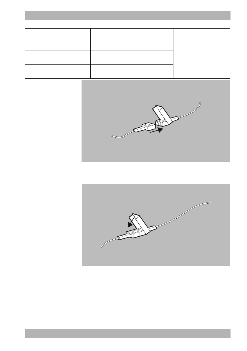
4 Preparation
Pulse oximetry sensor Patient group Application site
Disposable sensor for adults
(Adult)
Disposable sensor for children
(Pediatric)
Disposable sensor for infants
(Infant)
> 30 kg body weight
10 kg-50 kg body weight
10 kg-20 kg body weight
Finger/large toe
3. Connect the selected pulse oximetry sensor to the pulse
oximetry sensor connecting cable.
WM 68201 12/2017
4. Press the lock until it clicks into place.
5. Switch on the device (see "5.1 Switching the device on", page
76).
6. Select the patient group in the start menu.
MEDUCORE Standard
2
EN 61
Page 62

4 Preparation
7. Attach the pulse oximetry sensor:
Pulse oximetry
sensor
SoftTip® sensor
Special feature:
The finger mark
must point
upwards
Wrap sensor
Special feature:
The sensor's
transmitter and
receiver must be
aligned to face
each other on one
axis.
Attachment
Ear-clip sensor
62 EN MEDUCORE Standard
WM 68201 12/2017
2
Page 63

4 Preparation
Pulse oximetry
sensor
Disposable
sensor
Special feature:
The sensor's
transmitter and
receiver must be
aligned to face
each other on one
axis.
Attachment
When doing so, please note:
• The site must have a good blood supply.
• When attaching to the finger: If possible, use the ring or
middle finger of the non-dominant hand.
WM 68201 12/2017
8. Check whether the oxygen saturation values displayed on the
device are plausible.
Result A pulse oximetry sensor is connected.
MEDUCORE Standard
2
EN 63
Page 64

4 Preparation
4.6 Connecting the ECG cable and ECG electrodes
Damage to the device caused by ingress of liquids!
The device is only protected from water jets as per IP55 when the
battery is inserted, the water jet protection for the SD card slot is
closed and the lines for the ECG, SpO
connecting tube including NIBP cuff are connected. Ingress of
liquids and dust may damage the device, components, and
accessories.
⇒ Do not immerse the device, components, or accessories in
liquids.
⇒ Only operate the device with the battery inserted.
⇒ Always close the water jet protection of the SD card slot.
⇒ Always leave the lines for ECG, SpO
connecting tube including NIBP cuff connected.
, trunk cable and NIBP
2
, trunk cable and NIBP
2
1. Connect the ECG connector of the ECG cable to the ECG
connection for the ECG cable on the device.
2. Bare the patient's torso.
64 EN MEDUCORE Standard
WM 68201 12/2017
2
Page 65
4 Preparation
Risk of injury due to air/moisture between ECG electrodes and
the patient's skin!
Air (e.g. in the case of hirsute patients) or moisture between the
ECG electrodes and the patient's skin impair the quality of the
ECG signal and falsify the measurement results. This can injure the
patient.
⇒ Remove hair in hirsute patients.
⇒ Rub the patient's skin dry.
⇒ Wipe down oily skin with an alcohol pad.
3. If necessary: Remove hair from the torso.
4. If necessary: Rub damp spots on the torso dry.
5. If necessary: Wipe down oily skin with an alcohol pad.
6. Remove the protective backing from the ECG electrodes.
Risk of injury from incorrect positioning of the ECG
electrodes!
Incorrectly positioned ECG electrodes impair the quality of the
ECG signal and falsify measurements.
⇒ Select the electrode position according to the illustration.
⇒ Position the ECG electrodes so that defibrillation is possible.
⇒ Maintain distance from the defibrillation electrodes.
⇒ Do not position ECG electrodes on tendons or muscle groups.
WM 68201 12/2017
MEDUCORE Standard
2
EN 65
Page 66

4 Preparation
R/RA
N/RL
F/LL
L/LA
7. Stick and firmly press on the ECG electrodes as follows:
Code 1 (Europe) Code 2 (America)
Electrode
marking
Color coding
Electrode
marking
Color coding Application site
R Red RA White
L Yellow LA Black
F Green LL Red
N Black RL Green
Right arm; shortened:
under right collarbone
Left arm; shortened:
under left collarbone
Left leg; shortened: Left
groin crease, centrally to
leg axis
Right leg; shortened:
Right groin crease,
centrally to leg axis
4-1 Regular position for ECG electrodes
66 EN MEDUCORE Standard
2
WM 68201 12/2017
Page 67

4 Preparation
R/RA
N/RL
L/LA
F/LL
4-2 Shortened position for ECG electrodes
8. If the ECG electrodes are used at the same time as the
defibrillation electrodes: Do not allow ECG electrodes and
defibrillation electrodes to overlap.
9. If necessary: Stroke out any trapped air from under the ECG
electrodes.
10. Clip the ECG cable to the individual ECG electrodes.
11. Switch on the device (see "5.1 Switching the device on", page
76).
WM 68201 12/2017
12. Select the patient group in the start menu.
13. Check whether the ECG curves for ECG measurement
displayed on the device are plausible.
Result The ECG cable and the ECG electrodes are connected.
MEDUCORE Standard
2
EN 67
Page 68

4 Preparation
4.7 Attaching the NIBP cuff
Damage to the device caused by ingress of liquids!
The device is only protected from water jets as per IP55 when the
battery is inserted, the water jet protection for the SD card slot is
closed and the lines for the ECG, SpO
connecting tube including NIBP cuff are connected. Ingress of
liquids and dust may damage the device, components, and
accessories.
⇒ Do not immerse the device, components, or accessories in
liquids.
⇒ Only operate the device with the battery inserted.
⇒ Always close the water jet protection of the SD card slot.
⇒ Always leave the lines for ECG, SpO
connecting tube including NIBP cuff connected.
The following section describes how to attach the NIBP cuff. The
Instructions for Use provided by the NIBP cuff manufacturer are
binding for attachment. Follow these Instructions for Use.
2
, trunk cable and NIBP
, trunk cable and NIBP
2
1. Connect the NIBP connecting tube to the NIBP connection on
the device.
68 EN MEDUCORE Standard
WM 68201 12/2017
2
Page 69

4 Preparation
Risk of injury due to incorrect NIBP cuff!
An incorrectly selected or used NIBP cuff can lead to patient
injuries.
⇒ Attach the NIBP cuff so that the blood supply is not stopped.
⇒ Do not attach the NIBP cuff to a limb with an intravenous
infusion.
⇒ Do not attach the NIBP cuff to a limb with a shunt.
⇒ Do not attach the NIBP cuff to a limb with open wounds or
burns.
⇒ In the case of patients who have undergone a mastectomy, do
not attach the NIBP cuff to the affected side. In the case of
patients who have undergone double mastectomies, attach
the NIBP cuff to the non-dominant arm.
⇒ Do not attach the NIBP cuff to a limb with poor circulation.
2. Select the NIBP cuff which is suitable for the patient's limb as
per the following table.
Designation Color Limb circumference
Thigh
Thigh Brown 38-50 cm
Upper arm
Large Adult plus Dark red 40-55 cm
Adult plus Dark blue 28-40 cm
Adult Dark blue 23-33 cm
Small Adult Turquoise 17-25 cm
Child Green 12-19 cm
Infant Orange 8-13 cm
WM 68201 12/2017
MEDUCORE Standard
2
EN 69
Page 70

4 Preparation
Select a
larger one
Right sizeSelect a
smaller one
RANGE
When doing so, please note:
• The index printed on the NIBP cuff must be within the
printed range.
• If the index marking does not extend into the printed
range: Select a larger NIBP cuff.
• If the index marking extends beyond the printed range:
Select a smaller NIBP cuff.
70 EN MEDUCORE Standard
• In the case of disposable cuffs for neonates, use adapter
tube (WM 45467).
3. Switch on the device (see "5.1 Switching the device on", page
76).
Risk of injury due to incorrectly selected patient group!
If the incorrect patient group is selected, the contact pressure of
the NIPB cuff may be too high and injure the patient.
⇒ Adapt the patient group to the patient.
⇒ If necessary: Change the patient group in the application
menu.
4. Select the patient group in the start menu.
2
WM 68201 12/2017
Page 71

4 Preparation
5. Connect the NIBP connecting tube to the tube of the NIBP cuff.
6. Turn the two tubes towards each other until they lock into
place.
Risk of injury due to incorrectly attached NIBP cuff!
An incorrectly attached NIBP cuff can result in excessive contact
pressure. This can stop the blood supply and injure the patient.
⇒ Attach the NIBP cuff so that the blood supply is not stopped.
⇒ Do not attach the NIBP cuff to a limb with an intravenous
infusion.
⇒ Do not attach the NIBP cuff to a limb to which an SpO
sensor
2
is already attached.
⇒ Do not attach the NIBP cuff to a limb with open wounds or
burns.
⇒ With long-term NIBP monitoring, check the position of the
NIBP cuff regularly and, if necessary, reposition.
⇒ Do not attach the NIBP cuff to a limb with poor circulation.
⇒ Do not bend or crush the NIBP cuff tube or the NIBP connecting
tube.
WM 68201 12/2017
MEDUCORE Standard
2
EN 71
Page 72

4 Preparation
7. Attach the empty NIBP cuff to fit closely around the patient's
limb.
When doing so, please note:
• The skin below the NIBP cuff must be undamaged.
• The NIBP cuff must fit tightly around the limb.
• The artery (“Artery”) marking of the NIBP cuff must be
positioned above the artery and point toward the hand/
foot.
• If the NIBP cuff is attached to the arm: The NIBP cuff must
be positioned level with the heart.
8. Once the NIBP measurement is complete: Remove the NIBP
cuff.
Result An NIBP cuff which is suitable for the patient is attached.
72 EN MEDUCORE Standard
WM 68201 12/2017
2
Page 73

4.8 Using the SD card
Loss of data due to incorrect SD card!
SD cards not purchased from WEINMANN Emergency may have
reduced functionality or result in the loss of data.
⇒ Only use SD cards from WEINMANN Emergency.
⇒ Do not use the SD card for third-party files.
Damage to the device caused by ingress of liquids!
The device is only protected from water jets as per IP55 when the
battery is inserted, the water jet protection for the SD card slot is
closed and the lines for the ECG, SpO
connecting tube including NIBP cuff are connected. Ingress of
liquids and dust may damage the device, components, and
accessories.
⇒ Do not immerse the device, components, or accessories in
liquids.
⇒ Only operate the device with the battery inserted.
⇒ Always close the water jet protection of the SD card slot.
⇒ Always leave the lines for ECG, SpO
connecting tube including NIBP cuff connected.
4.8.1 Inserting an SD card
4 Preparation
, trunk cable and NIBP
2
, trunk cable and NIBP
2
WM 68201 12/2017
The device has only a limited internal memory. To record session
data over an extended period of time, you must insert an SD card:
1. Open the water jet protection of the SD card slot.
MEDUCORE Standard
2
EN 73
Page 74

4 Preparation
2. Push the SD card into the SD card slot until it clicks into place.
When doing so, please note: The beveled corner of the SD card
must be at the front on the right during insertion.
3. Close the water jet protection to protect the device from the
ingress of dust and water.
Result The SD card is inserted in the device and ready for use.
After the device is switched on, the symbol appears on the
display.
4.8.2 Removing the SD card
Requirement An SD card is in the SD card slot.
1. Open the water jet protection of the SD card slot.
Incorrect use may result in loss of data!
If you remove the SD card while the symbol is displayed or
during an ongoing session, data may be lost or the SD card
damaged.
⇒ Only remove the SD card if the device is switched off or the
following symbols or are displayed.
2. Briefly press in the SD card.
The SD card is ejected slightly.
3. Remove SD card.
4. Close the water jet protection to protect the device from the
ingress of dust and water.
74 EN MEDUCORE Standard
WM 68201 12/2017
2
Page 75

Result The SD card is removed.
The symbol appears on the device display.
4 Preparation
WM 68201 12/2017
MEDUCORE Standard
2
EN 75
Page 76

5 Operation
5 Operation
5.1 Switching the device on
Requirement • The ECG cable and the defibrillation electrodes are not
• A fully charged battery is inserted in the device.
1. Briefly press the On/Off button .
connected to the patient.
An automatic self-test starts, which runs through the following
sequence:
• Alarm light flashes and test tone sounds
• The start screen appears
• Shock standby indicator is illuminated
The self-test is successful when all of the steps have been
completed.
When doing so, please note:
• If the device was switched off for ≥ 30 s: The start menu
appears. The device starts with the presets in the operator
menu.
• If the device was switched off for < 30 s and, if whilst
switched on previously, patient measurements were taken
or an event was saved manually: The device skips the start
menu and starts in the preset start mode and with the
preset start view. The settings in the user menu from the
last session are retained and the device assigns the session
data to the last session.
• If the ECG cable and the defibrillation electrodes were
already connected to the patient at the start of the self-test:
The device skips the test of the ECG module and the
defibrillation module.
2. If one or more conditions are not met: Do not operate the
device.
3. Perform a function check (see "10.2 Performing a function
check", page 148).
76 EN MEDUCORE Standard
WM 68201 12/2017
2
Page 77

Action
Press the function
button
5 Operation
Result The device is switched on.
5.2 Switching the device off
1. Press and hold the On/Off button for at least 2 seconds.
Result The device is completely switched off.
5.3 Navigating in the device
Result
In a menu
The function is shown in the display, directly above the function button (e.g. AED or
Back).
Within a menu
item
In the start
menu
In a mode
Turn the navigation
knob
counterclockwise
Turn the navigation
knob clockwise
Press the navigation
knob
Press the menu
button
Press the view
button
WM 68201 12/2017
Navigate upwards Decrease value Navigate upwards -
Navigate
downwards
Select the menu
item
Close the menu Close the menu
---
Increase value
Confirm the set
value
Navigate
downwards
Select the menu
item
Activate the
operator menu
MEDUCORE Standard
-
Activate the application
menu
Activate the user menu
Switch view:
• Parameter view
•Curve view
2
EN 77
Page 78

5 Operation
Action
Result
In a menu
Within a menu
item
In the start
menu
In a mode
Press event button
Press the NIBP
button
Requirement The device is switched on (see "5.1 Switching the device on", page
---
---
Manually saves an
event in the data set.
• Activate the NIBP
• Start NIBP
5.4 Selecting the patient group
When you select a patient group, the presets which the operator
specified for this patient group are loaded. If the operator has not
specified presets, the factory settings are loaded.
76).
function mode
(press for < 2 s)
measurement
(press for > 2 s)
1. When the start menu is active: Select the patient group with
the navigation knob.
or
78 EN MEDUCORE Standard
WM 68201 12/2017
2
Page 79

5 Operation
If the timer has expired: The device automatically selects the
Adult patient group.
2. During ongoing operation: Open the application menu with
the navigation knob and change the patient group.
When doing so, please note: The Infant patient group is not
available in AED mode.
WM 68201 12/2017
Result The selected patient group is shown in the top right-hand
corner, next to the mode display.
MEDUCORE Standard
2
EN 79
Page 80

5 Operation
5.5 Performing defibrillation
5.5.1 Semi-automatic defibrillation in AED mode
The defibrillation sequence in the AED mode described here
corresponds to the device settings as delivered. The operator menu
enables you to adapt the device to users’ qualification level and to
provide optimal support to the latter during resuscitation measures
whilst taking the regional features into account.
Requirement • The trunk cable and defibrillation electrodes are connected (see
"4.4 Connecting the trunk cable and defibrillation electrodes",
page 57).
• The device is switched on (see "5.1 Switching the device on",
page 76).
• The patient group is selected (see "5.4 Selecting the patient
group", page 78).
Risk of injury due to missing battery in the AED mode and in
manual mode!
Without a battery, the capacitor for shock energy in the device
cannot charge. This prevents defibrillation and delays treatment.
⇒ Insert a battery before using the AED mode or the manual
mode.
Risk of injury due to unsuitable AED analysis algorithm in
children below one year of age!
The device's AED analysis algorithm is not designed for children
below one year of age and may result in injury to the child.
⇒ Do not use the AED mode on children below one year of age.
Delay in treatment due to simultaneous voice prompts from
defibrillator and ventilator!
If the defibrillator in AED mode is used in conjunction with a
ventilator which also guides the user through cardiopulmonary
resuscitation by means of voice prompts (e.g.
MEDUMAT Easy CPR), the simultaneous voice prompts from
defibrillator and ventilator may confuse the user, and delay
treatment.
⇒ When using the defibrillator in AED mode and a ventilator at
the same time, switch off the ventilator voice prompts.
80 EN MEDUCORE Standard
WM 68201 12/2017
2
Page 81

5 Operation
1. Select AED mode with the AED function button.
When doing so, please note:
• Depending on the patient group selected, the AED settings
from the operator menu which apply to this group are
taken as the basis.
• Upon connection of the defibrillation electrodes for
children, the shock energy is limited to 100 J. If a higher
shock energy was preset in the device, the device reduces
the shock energy to 100 J.
• The “Infant” patient group is not available since the AED
analysis algorithm is not suitable for children under the age
of 1 year.
• No alarms are displayed or emitted in AED mode.
Risk of injury due to incorrectly selected patient group!
With an incorrectly selected patient group in AED mode, the shock
energy, the number of shocks in series, the energy curve and/or
the metronome frequency, the ventilation pause and the
compression/ventilation ratio may not be suitable for the patient
and could result in patient injury.
⇒ Adapt the patient group to the patient.
⇒ If necessary: Change the patient group in the application
menu.
WM 68201 12/2017
2. If necessary: Open the application menu with the navigation
knob and change the patient group.
When doing so, please note: In AED mode, only the adult and
child patient groups are available in the application menu.
3. If necessary: Open the application menu with the navigation
knob and change the device volume.
4. Follow the voice prompts and AED instructions.
MEDUCORE Standard
2
EN 81
Page 82

5 Operation
If you operate the device via the line power and the inserted
battery is defective or if the battery does not have sufficient
capacity to charge the capacitor for shock energy in AED mode,
the device guides you through cardiopulmonary resuscitation
without creating a shock standby. If you subsequently insert an
undamaged and sufficiently charged battery, the device starts the
cardiac rhythm analysis immediately and prepares for a shock
standby.
Result The device performs a cardiac rhythm analysis. The cardiac rhythm
analysis has one of two results:
• Shock required (see " Shock required", page 82)
or
• Shock not required (see " Shock not required", page 84)
Shock required
The device performs a cardiac rhythm analysis, charges for shock
delivery and outputs the message:
Voice prompt AED instruction
Stand clear of the patient Stand clear of the patient
Cardiac rhythm is being analyzed Analysis
If, based on the cardiac rhythm analysis, the device determines that
a shock is required, the device outputs the message:
Voice prompt AED instruction
Shock required Shock required
Press shock button Press shock button
The shock button flashes and an audio alarm sounds.
82 EN MEDUCORE Standard
WM 68201 12/2017
2
Page 83

5 Operation
Risk of injury from electric shock!
The electric shock administered to the patient may result in injury
to the patient, user or bystanders.
⇒ Stand clear of the patient.
⇒ Keep patient away from liquids (e.g. blood, gel or saline
solution).
⇒ Do not touch parts in contact with the patient
(e.g. bed frames or stretchers).
⇒ Keep your distance from liquids in contact with the patient.
⇒ Clearly warn bystanders to stand clear of the patient or parts in
contact with the patient and to keep their distance from liquids
in contact with the patient.
Damage to the device caused by removal of the defibrillation
electrodes during shock delivery!
Removal of the defibrillation electrodes during shock delivery can
cause damage to the device.
⇒ Always leave defibrillation electrodes connected to the device
and the patient during shock delivery.
1. Deliver a shock with the shock button .
When doing so, please note: If the shock button is not
pressed, the capacitor for the shock energy discharges
automatically after 15 seconds.
WM 68201 12/2017
Result The patient receives an electric shock. The shock energy
corresponds to the settings in the operator menu. Upon delivery,
the device settings are as follows:
Patient group Setting
Child
for adults
First shock 75 J, subsequent shocks
75 J
First shock 150 J, subsequent shocks
200 J
The device guides you through cardiopulmonary resuscitation by
means of voice prompts, AED instructions and the metronome
(see " Performing cardiopulmonary resuscitation", page 84). It
warns you again to stand clear of the patient after the preset time
has elapsed (120 seconds when delivered), in order to perform
another cardiac rhythm analysis.
MEDUCORE Standard
2
EN 83
Page 84
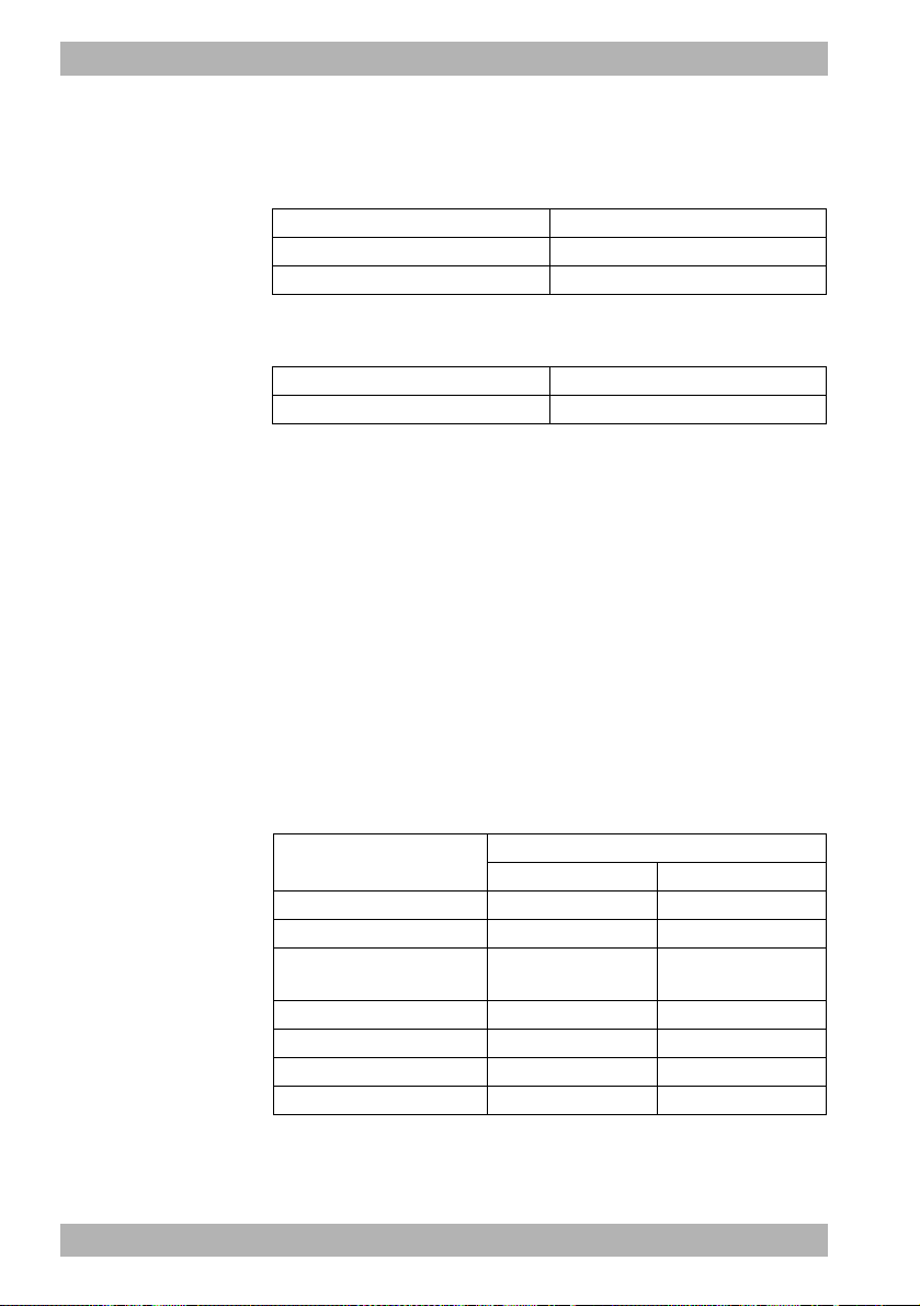
5 Operation
Shock not required
The device performs a cardiac rhythm analysis, charges for shock
delivery and outputs the message:
Voice prompt AED instruction
Stand clear of the patient Stand clear of the patient
Cardiac rhythm is being analyzed Analysis
If, based on the cardiac rhythm analysis, the device determines that
a shock is not required, the device outputs the message:
Voice prompt AED instruction
Shock not recommended Shock not recommended
1. Perform cardiopulmonary resuscitation (see " Performing
cardiopulmonary resuscitation", page 84).
Result The patient does not have a defibrillatable cardiac rhythm. The
device guides you through cardiopulmonary resuscitation by
means of voice prompts, AED instructions and the metronome. It
warns you again to stand clear of the patient after the preset time
has elapsed (120 seconds when delivered), in order to perform
another cardiac rhythm analysis.
Performing cardiopulmonary resuscitation
This section describes cardiopulmonary resuscitation in the AED
mode. Upon delivery, the device performs cardiopulmonary
resuscitation with the following parameters; these, however, can
be adapted by the operator:
Setting
Duration of CPR phase 120 s 120 s
Ventilation pause 5 s 5 s
Compression/ventilation
ratio
Start in intubation mode? No No
CPR voice prompts No No
Metronome frequency 100/min 100/min
Start analysis automatically Yes Yes
84 EN MEDUCORE Standard
Patient group
for adults Child
30:2 15:2
WM 68201 12/2017
2
Page 85

5 Operation
After cardiac rhythm analysis and shock delivery (if necessary), the
device instructs you to carry out cardiopulmonary resuscitation.
A metronome provides a guide for chest compressions.
Voice prompt (optional) AED instruction
Carry out cardiopulmonary
resuscitation
Cardiopulmonary resuscitation
1. Perform chest compressions:
• 30 chest compressions for the adult patient group
• 15 chest compressions for the child patient group
• Continuous chest compression with intubated patients
When doing so, please note: The metronome sets the ideal
frequency.
After 30/15 metronome beats, there is a pause to allow for
ventilation:
Voice prompt (optional) AED instruction
Ventilate twice Ventilate twice
2. Ventilate the patient twice.
The device outputs the message:
WM 68201 12/2017
Voice prompt (optional) AED instruction
Carry out cardiopulmonary
resuscitation
Cardiopulmonary resuscitation
3. Repeat the cardiopulmonary resuscitation sequence.
4. If the patient is intubated: Press the Intub. function button.
The metronome sets a continuous frequency.
5. If the patients shows vital signs (breathing, response): Take
basic patient care steps.
6. After each cardiopulmonary resuscitation cycle: Check that the
defibrillation electrodes are positioned correctly.
Result Cardiopulmonary resuscitation has been performed.
MEDUCORE Standard
2
EN 85
Page 86

5 Operation
5.5.2 Manual defibrillation (only with Manual
defibrillation option)
This function is only available if it has been enabled and activated
by the operator: Operator menu | System settings | Enable options
| Manual mode (see "8.8 System settings", page 137).
If you are the operator of the device and have access to the
operator menu, you can disable the manual mode: Operator menu
| System settings | Disable functions | Manual mode (see "8.8
System settings", page 137).
Requirement • The trunk cable and defibrillation electrodes are connected (see
"4.4 Connecting the trunk cable and defibrillation electrodes",
page 57).
• The device is switched on (see "5.1 Switching the device on",
page 76).
• The patient group is selected (see "5.4 Selecting the patient
group", page 78).
Risk of injury due to lack of knowledge and failure to follow
guidelines in the manual mode!
The use of the manual mode by users without medical
qualifications and training in defibrillation and/or failure to follow
guidelines can result in injury to the patient, user or bystanders.
⇒ Only use the manual mode if the user has a medical
qualification and is familiar with the operation of the device.
⇒ Follow the defibrillation guidelines.
⇒ Observe national and regional provisions on defibrillation.
⇒ Observe organizational guidelines on defibrillation.
Risk of injury due to missing battery in the AED mode and in
manual mode!
Without a battery, the capacitor for shock energy in the device
cannot charge. This prevents defibrillation and delays treatment.
⇒ Insert a battery before using the AED mode or the manual
mode.
86 EN MEDUCORE Standard
WM 68201 12/2017
2
Page 87

5 Operation
Risk of injury due to incorrectly selected patient group!
If the wrong patient group is selected, the shock energy may be
insufficient or too high for the selected patient group and can
injure the patient.
⇒ Adapt the patient group to the patient.
⇒ If necessary: Change the patient group in the application
menu.
1. If necessary: Open the application menu with the navigation
knob and change the patient group.
2. Select manual mode with the Manual function button. When
doing so, please note:
• It is not possible to switch to the parameter view in manual
mode. If you activate the manual mode from the parameter
view, there is an automatic switchover to curve view since,
for manual shock delivery, the ECG evaluation on the
display is required.
• Audio alarm output is deactivated in manual mode. To
activate the audio alarm output, press the alarm button
briefly.
3. Evaluate the ECG lead.
WM 68201 12/2017
4. If necessary: Select another ECG lead by pressing the Lead
function button.
5. If shock is required: Select shock energy by pressing the
Energy function button. When doing so, please note: Upon
connection of the defibrillation electrodes for children
(Pediatric), the defibrillation energy is automatically restricted
to 100 J. It is not possible to set a higher energy in manual
mode.
6. Press the Charging function button.
The charge progress bar appears. A rising charge tone sounds
until the device is ready to deliver the shock. When the device
is charged, a sequence of tones sounds which signalizes shock
standby and the shock button flashes.
7. Check ECG derivations to ascertain whether a shock is still
required.
MEDUCORE Standard
2
EN 87
Page 88

5 Operation
Risk of injury from electric shock!
The electric shock administered to the patient may result in injury
to the patient, user or bystanders.
⇒ Stand clear of the patient.
⇒ Keep patient away from liquids (e.g. blood, gel or saline
solution).
⇒ Do not touch parts in contact with the patient (e.g. bed frames
or stretchers).
⇒ Keep your distance from liquids in contact with the patient.
⇒ Clearly warn bystanders to stand clear of the patient or parts in
contact with the patient and to keep their distance from liquids
in contact with the patient.
Damage to the device caused by removal of the defibrillation
electrodes during shock delivery!
Removal of the defibrillation electrodes during shock delivery can
cause damage to the device.
⇒ Always leave defibrillation electrodes connected to the device
and the patient during shock delivery.
8. Deliver a shock with the shock button .
When doing so, please note: If the shock button is not
pressed, the capacitor for the shock energy discharges
automatically after 30 seconds.
9. If necessary: Cancel shock charging by pressing the Cancel
function button or by switching to another mode.
Result The patient receives an electric shock.
88 EN MEDUCORE Standard
WM 68201 12/2017
2
Page 89

5 Operation
5.6 Performing pulse oximetry monitoring
Requirement • The device is switched on (see "5.1 Switching the device on",
page 76).
• A patient group is selected (see "5.4 Selecting the patient
group", page 78).
• A pulse oximetry sensor is connected (see "4.5 Connecting the
pulse oximetry sensor", page 60).
1. If necessary: Select another patient group (see "5.4 Selecting
the patient group", page 78).
2. If necessary: Select the monitor mode by pressing the Monitor
function button.
3. If necessary: Switch between parameter view and curve view
with the view button .
WM 68201 12/2017
4. In the parameter view: Read off the measured values for
arterial oxygen saturation (SpO
or
MEDUCORE Standard
) and pulse rate (Pulse).
2
2
EN 89
Page 90

5 Operation
In the curve view: Evaluate the SpO
the measured values for arterial oxygen saturation (SpO
curve (Pleth) and read off
2
) and
2
pulse rate (Pulse).
5. If necessary: Make the following SpO
menu (see "7.3.3 SpO
settings", page 114):
2
settings in the user
2
• Adapt the feed speed of the plethysmogram
• Give the pulse tone output priority over the heart rate tone
output so that the tone pitch is output depending on
oxygen saturation, even when the ECG cable or pad
electrodes are connected to the patient.
6. If necessary: Set alarm limits in the user menu (see "7.3.1
Alarm settings", page 111).
or
Set automatic alarm limits in the application menu (see "6
Application menu", page 106).
7. If necessary: Deactivate the pulse tone with the heart rate tone/
pulse tone function button.
8. If there are artifacts in the SpO
not sufficient (bar in the SpO
curve or if the signal quality is
2
parameter field): Reposition the
2
pulse oximetry sensor on the patient’s limb.
Result Pulse oximetry monitoring is performed.
5.7 Performing ECG monitoring
Requirement • The device is switched on (see "5.1 Switching the device on",
page 76).
• A patient group is selected (see "5.4 Selecting the patient
group", page 78).
• An ECG cable and the ECG electrodes are connected (see "4.6
Connecting the ECG cable and ECG electrodes", page 64).
1. If necessary: Select another patient group (see "5.4 Selecting
the patient group", page 78).
2. If necessary: Select the monitor mode by pressing the Monitor
function button.
90 EN MEDUCORE Standard
2
WM 68201 12/2017
Page 91

5 Operation
3. If necessary: Open the application menu with the navigation
knob and change the device volume.
4. If necessary: Switch between parameter view and curve view
with the view button .
5. Evaluate the ECG leads and heart rate.
WM 68201 12/2017
6. If necessary: Select another ECG lead by pressing the Lead
function button.
7. If necessary: Make the following ECG settings in the user menu
(see "7.3.2 ECG settings", page 113):
• Adapt amplitude scaling in order to adapt the displayed
height of the ECG curve to the ECG measuring signal.
• Activate autoscaling in order to have the height of the ECG
curve automatically displayed adapted to the ECG
measuring signal.
• Adapt the feed speed of the ECG curve.
• Activate the filter to filter disturbances caused by the line
supply network out of the ECG display.
If necessary: Set alarm limits in the user menu (see "7.3.1
Alarm settings", page 111).
or
MEDUCORE Standard
2
EN 91
Page 92

5 Operation
Set automatic alarm limits in the application menu (see "6
Application menu", page 106).
8. If necessary: Switch off the heart rate tone/pulse tone with the
function button .
The symbol appears.
9. If necessary: Open the application menu with the navigation
knob and change the device volume.
Result ECG monitoring is performed.
5.8 Performing non-invasive blood pressure measurement (NIBP)
NIBP measurement technology has been optimized for measuring
blood pressure with a normal sinus rhythm. Cardiac arrhythmias
can impair the ability of the non-invasive blood pressure
measurement module to record correct measured values.
Furthermore, arteriosclerosis, reduced circulation, diabetes, old
age, pregnancy, preeclampsia, kidney disease, trembling, shivers
and the use of a cardiac pacemaker can impair the ability of the
non-invasive blood pressure measurement module to record
correct measured values.
5.8.1 NIBP measurement
With an individual NIBP measurement, the device inflates the NIBP
cuff to the set pressure (initial NIBP cuff pressure). The user can
adapt the initial NIBP cuff pressure (Initial function button). To
determine the patient’s systolic and diastolic blood pressure, the air
is slowly released from the NIBP cuff whilst measuring the pressure
of the pulse wave. The values for the diastolic and systolic blood
pressure are determined from this and shown in the display. At the
end of the NIBP measurement, the device releases the remaining
air from the NIBP cuff.
The NIBP measurement can be influenced by various factors:
• Application site of the NIBP cuff
92 EN MEDUCORE Standard
WM 68201 12/2017
2
Page 93

5 Operation
• Patient position (ideal position: Sitting comfortably, legs not
crossed, feet flat on the floor, back and arm supported, middle
of the NIBP cuff level with the right heart atrium)
• Exertion (recommendation: Patient should rest for 5 minutes
before the measurement, keep still during the measurement
and not speak)
• Physiological condition.
Performing the NIBP measurement
Requirement • An NIBP cuff is connected to the NIBP connecting tube (see
"4.7 Attaching the NIBP cuff", page 68).
• The device is switched on (see "5.1 Switching the device on",
page 76).
• The patient group is set (see "5.4 Selecting the patient group",
page 78).
Risk of injury due to incorrectly selected patient group
The device only provides correct measured values if the
appropriate patient group is selected. An incorrect patient group
can lead to incorrect measurements and patient injuries.
⇒ Select the suitable patient group for the patient (see "5.4
Selecting the patient group", page 78).
WM 68201 12/2017
Risk of injury due to incorrectly selected NIBP cuff
The device only provides correct measured values if the
appropriate NIBP cuff is selected. An unsuitable NIBP cuff can lead
to incorrect measurements and patient injuries.
⇒ Select the suitable NIBP cuff for the patient (see "4.7 Attaching
the NIBP cuff", page 68).
1. Press the NIBP button for < 2 s.
The device switches to NIBP function mode.
2. If necessary: Select another patient group (see "5.4 Selecting
the patient group", page 78).
The NIBP module is configured in the device accordingly with
the selected patient group.
MEDUCORE Standard
2
EN 93
Page 94
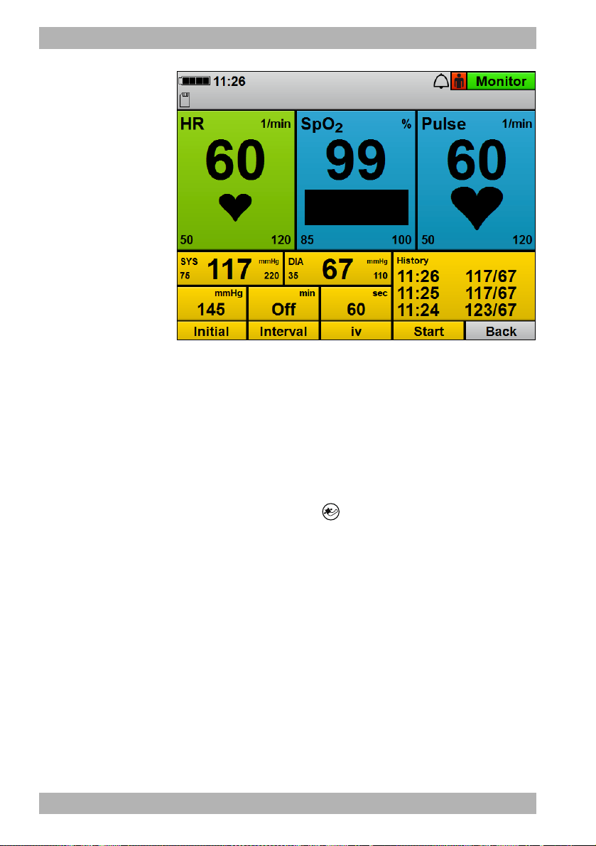
5 Operation
3. If necessary: Adapt the initial NIBP cuff pressure to the patient
with the Initial function button and navigation knob.
When doing so, please note: Following successful NIBP
measurement, the initial NIBP cuff pressure adapts to the
patient (approx. 30 mmHg above the systolic measured value
of the previous NIBP measurement).
4. Press the Start function button.
or
Press the NIBP button for > 2 s.
An NIBP measurement starts. At the end of the measurement,
the device shows the systolic and diastolic arterial pressure.
5. Evaluate the NIBP measurement.
6. If implausible measured values are shown:
• Check whether the NIBP cuff is correctly selected and
attached.
• If necessary: Repeat the NIBP measurement.
7. If necessary: Cancel the NIBP measurement with the Stop
function button.
The device releases the pressure from the NIBP cuff.
94 EN MEDUCORE Standard
WM 68201 12/2017
2
Page 95

5 Operation
8. If necessary: Set alarm limits in the user menu (see "7.3.1
Alarm settings", page 111).
or
Set automatic alarm limits in the application menu (see "6
Application menu", page 106).
9. If necessary: Press the Back function button.
or
Press the NIBP button for < 2 s.
The device ends the NIBP function mode and switches to the
set mode.
Result Non-invasive blood pressure measurement has been performed.
5.8.2 Interval measurement
During an interval measurement (Interval function button), the
device performs several successive NIBP measurements. The
interval duration indicates the time between two successive NIBP
measurements.
Performing the interval measurement
WM 68201 12/2017
Requirement • An NIBP cuff is connected to the NIBP connecting tube (see
"4.7 Attaching the NIBP cuff", page 68).
• The device is switched on (see "5.1 Switching the device on",
page 76).
• The patient group is set (see "5.4 Selecting the patient group",
page 78).
1. Press the NIBP button for < 2 s.
The device switches to NIBP function mode.
2. If necessary: Select another patient group (see "5.4 Selecting
the patient group", page 78).
The NIBP module is configured in the device accordingly with
the selected patient group.
3. Press the Interval function button.
4. Set the interval duration using the navigation knob.
MEDUCORE Standard
2
EN 95
Page 96

5 Operation
5. Press the Start function button.
or
Press the NIBP button for < 2 s.
An NIBP measurement starts. At the end of the measurement,
the device shows the systolic and diastolic arterial pressure, the
timer expires and the next measurement starts automatically.
6. Evaluate the NIBP measurement.
7. If necessary: Cancel the NIBP measurement with the Stop
function button.
The device releases the pressure from the NIBP cuff.
8. If necessary: Set alarm limits in the user menu (see "7.3.1
Alarm settings", page 111).
or
Set automatic alarm limits in the application menu (see "6
Application menu", page 106).
9. If necessary: Press the Back function button.
or
Press the NIBP button for < 2 s.
The device ends the NIBP function mode and switches to the
set mode.
Result The interval measurement has been performed.
5.8.3 Venous stasis
With venous stasis (iv function button), the device inflates the NIBP
cuff and maintains this pressure for the time preset in the operator
menu. The venous blood return flow is impeded and the user can
puncture one of the patient’s veins. The venous stasis function is
only available to the Adult patient group.
If you are the operator of the device and have access to the
operator menu, you can disable the Venous stasis function:
Operator menu | System settings | Disable functions | Venous stasis
(see "8.8 System settings", page 137).
96 EN MEDUCORE Standard
WM 68201 12/2017
2
Page 97

5 Operation
Performing venous stasis
Requirement • An NIBP cuff is connected to the NIBP connecting tube (see
"4.7 Attaching the NIBP cuff", page 68).
• The device is switched on (see "5.1 Switching the device on",
page 76).
•The Adult patient group is set.
•A mode is set.
1. Press the NIBP button for < 2 s.
The device switches to NIBP function mode.
2. Press the iv function button.
The NIBP cuff is inflated to the pressure set in the operator
menu. The timer displaying the duration of venous stasis
expires. During the venous stasis time, the pressure of the NIBP
cuff is maintained.
Risk of injury from deflating the pressure in the NIBP cuff too
soon.
On expiry of the timer, the venous stasis ends automatically. If the
intravenous access is not created during this time, this can injure
the patient.
⇒ Create the access before the timer expires.
⇒ If the access cannot be created before the timer expires: Abort
and provide medical treatment to the puncture site.
WM 68201 12/2017
3. Create the intravenous access.
4. Once the access has been created: Release the pressure from
the NIBP cuff with the Stop function button.
Result A venous stasis is created.
5.9 Using the audio alarm output
5.9.1 Canceling the audio alarm output
Requirement An alarm is active and is audible.
1. Briefly (< 2 s) press the alarm button .
MEDUCORE Standard
2
EN 97
Page 98
5 Operation
Result The audio alarm output is canceled for this alarm. The symbol
appears on the display and no audio signal is output for this alarm.
5.9.2 Pausing/muting the audio alarm output
Requirement An alarm is active and is audible.
1. Press and hold the alarm button (> 2 s.).
Result The audio alarm output pauses for the time set in the operator
menu (Operator menu | Alarm settings | Pause audio). The symbol
appears on the display. If you set the time in the operator
menu to ∞ (infinite), the audio alarm output is permanently paused
(audio alarm output is muted). The symbol appears on the
display.
If set, a reminder signal will remind you at certain intervals that the
audio alarm output is paused or muted. You can set the reminder
signal in the operator menu (Operator menu | Alarm settings |
Reminder signal).
5.9.3 Canceling muting or pausing of audio alarm
output
Requirement An alarm is active and is muted or paused.
1. Briefly (< 2 s) press the alarm button .
or
Switch modes.
Result Muting or pausing of audio alarm output is canceled.
5.10 Saving the event manually in the session data set
Measured values and the user actions performed on the device are
saved in the internal memory and on the SD card.
With the event button , events which cannot be recorded by
the device automatically (e.g. intubation, medication
administration, etc.) can be saved in the data set in order to
subsequently assign them chronologically during evaluation.
98 EN MEDUCORE Standard
2
WM 68201 12/2017
Page 99

5 Operation
Requirement • The device is switched on (see "5.1 Switching the device on",
page 76).
• The patient group is set (see "5.4 Selecting the patient group",
page 78).
1. Press event button .
Result The device saves an event with the designation Manual event in
the session data set and an acknowledgment tone is heard.
5.11 Reprocessing the device after use
1. Remove disposable articles from the patient and dispose of
them:
• Defibrillation electrodes
• ECG electrodes
• Disposable pulse oximetry sensor
• Disposable NIBP cuff for neonates
2. Remove the short-term NIBP cuffs from the patient and check
the duration of use.
WM 68201 12/2017
3. If necessary: Include new short-term NIBP cuffs with the device.
4. Include new disposable articles and, if necessary, a short-term
NIBP cuff with the device.
5. Hygienically reprocess the device, components and accessories
(see "9 Hygienic reprocessing", page 144).
6. If necessary: Place components and accessories on the portable
system or in the protective transport bag.
7. If necessary: Store the device, components and accessories (see
"13 Storage", page 172).
Result The device is reprocessed following use.
MEDUCORE Standard
2
EN 99
Page 100

5 Operation
5.12 Saving session data/status log
The device always saves the session data and status log to its
internal memory. The status log is required in order to be able to
analyze the data should servicing be necessary.
If an SD card is inserted in the SD card slot, the device automatically
saves the data to the SD card in addition. The symbol appears
on the display. In the first minute after a new session is started, the
device only saves the session data temporarily to the device
memory, but not yet to the SD card. If you switch off the device
during this time, the session data is lost. After the first minute, the
device permanently saves the data to the internal device memory
and to the SD card (provided that the SD card was inserted in the
SD card slot before the start of the session). If the SD card is full,
the symbol appears.
If you switch off the device and then switch it on again after < 30 s,
the device continues saving the data.
If you switch off the device and then switch it on again after > 30 s,
the device creates a new session data set.
Saving session data/status log to SD card
Requirement An SD card is in the SD card slot.
1. Switch on the device (see "5.1 Switching the device on", page
76).
The start menu appears.
2. Press the menu button to call up the operator menu.
3. Enable the operator menu with the access code.
4. Select System settings | SD card.
5. Select the menu item Export internal memory to SD card.
or
Select the menu item Export status log to SD card.
The message Start export? appears.
6. Press the function button OK to start copying.
The session data/status log are saved to the SD card. During the
copying process, the symbol appears
100 EN MEDUCORE Standard
2
WM 68201 12/2017
 Loading...