

Page 1
MEDUCORE Easy
Automatic external defibrillator
Device nos. 1000 to 1340 from device no. 1341 with ILCOR 2005
MEDUCORE Easy
MEDUCORE Easy
Service and Repair instructions
with Battery-Pack
with Rechargeable Battery-Pack
Page 2

Contents
Introduction
1.
Overview
2.
Description of Equipment
2.1
2.2
2.3
2.4
3.
Cleaning and disinfecting instructions
4.
Checking the device
4.1
4.2
4.3
4.4
4.5
4.6
4.7
4.8
4.9
4.10
4.11
4.12
4.13
4.14
5.
Maintenance
5.1
5.2
5.3
5.4
6.
Safety related check according to
§6 Medicinal products and Users ordinance .
6.1
6.2
6.3
6.4
6.5
. . . . . . . . . . . . . . . . . . . . . . . . 3
. . . . . . . . . . . . . . . . . . . . . . . . . . 4
. . . . . . . . . . . . . . 5
Intended use
Scope of application
User qualification
Functional description
Testing parts needed
Preparations for testing
Entering the device data
Checking the devices self testing
Checking the volume levels
Testing the ECG detection, current input,
shock button and shock output
Checking the procedure display
and capacitor discharge
Checking the info-button
and reading contact
Checking the status LEDs
Checking the condition of the exterior,
the equipment and the accessories
Checking the IRDA interface and the
software version
Checking the maintenance and safety
related check (SRC) stickers
Preparing a device for dispatch
following repair
Documentation
Intervals
Check the Battery/Rechargeable Battery.
Renew maintenance sticker
Disposal
General
Execution
Testing devices
Replace SRC sticker
Documentation
. . . . . . . . . . . . . . . . . . .
. . . . . . . . . . . . . .
. . . . . . . . . . . . . . . .
. . . . . . . . . . . . .
. . . . . . . . . . . . . . . . . . 9
. . . . . . . . . . . . . .
. . . . . . . . . . . .
. . . . . . . . . .
. . . . .
. . . . . . . . .
. . . . . . .
. . . . . . . . . .
. . . . . . . . . . . . .
. . . . . . . . . .
. . . . . . . . . . . . . . . .
. . . . . . . .
. . . . . . . . . . . . . . . .
. . . . . . . . . . . . . . . . .
. . . . . . . . . . . . . . . . . . . . . . 18
. . . . . . . . . . . . . . . . . . . . .
. . . . . . . . .
. . . . . . . . . . . . . . . . . . . . .
. . . . . . . . . . . . . . . . . . . . .
. . . . . . . . . . . . . . . . . . . .
. . . . . . . . . . . . . . . . .
. . . . . . . . . . . . .
. . . . . . . . . . . . . . . . .
. . . . . 8
10
10
10
11
11
12
13
13
. . . .
14
15
15
15
17
18
18
19
20
21
21
21
21
21
21
7.
Malfunctions and Rectification
8.
Repair information and repair instructions
8.1
General
8.2
5
5
5
6
9
9.
10.
11.
12.
13. Protocol . . . . . . . . . . . . . . . . . . . . . . . . . . . 44
Tools and facilities
8.3
Discharge high voltage capacitor
and open up device
8.4
Opening the device
8.5
Exchange the device lids
8.6
Close the device
8.7
Exchanging the capacitor
8.8
Replace the Real Time Clock batteries
8.9
Replacing the main circuit board
8.10
Exchanging pad plug cable
8.11
Exchanging the speaker
8.12
Exchange encasing, upper part
8.13
Exchanging encasing, lower part
Replacement parts
Tools and testing devices
10.1
General tools
10.2
Special tools
10.3
Software
10.4
Testing devices
Technical data
Technical Changes
12.1 Device: MEDUCORE Easy . . . . . . . . 43
12.2 Software . . . . . . . . . . . . . . . . . . . . 43
13.1 Repairs and maintenance protocol . . . . 44
13.2 Test record "Safety related check in
accordance with §6 of the MP BetreibV
(German Medicinal Products and Users
Ordinance)". . . . . . . . . . . . . . . . . . . 45
. . . . . . . . . . . . . . . . . . . . .
. . . . . . . . . . . . . . .
. . . . . . . . . . . . . . . . . . . 34
. . . . . . . . . . . . . . . . . .
. . . . . . . . . . . . . . . . . .
. . . . . . . . . . . . . . . . . . . . .
. . . . . . . . . . . . . . . . .
. . . . . . . . . . . . . . . . . . . . . . 39
. . . . . . . . . . . . . . . . . . . 43
. . . . . . . . . . . 22
. . 24
. . . . . . . . . . . . . .
. . . . . . . . . . . . .
. . . . . . . . . . . . .
. . . . . . . . . .
. . . . . . . . . .
. .
. . . . .
. . . . . . . .
. . . . . . . . . . .
. . . . . .
. . . . .
. . . . . . . . . . . . . . . 38
24
24
25
27
27
28
29
29
30
32
32
33
33
38
38
38
38
© Copyright WEINMANN GmbH & Co. KG.
The content and presentation are copyright protected and may only be used by authorised WEINMANN Service Partners in
the course of their service operations. The content must not be reproduced or passed on to third parties. The complete documents
must be returned on termination of the cooperation with WEINMANN.
2
Page 3

Introduction
WEINMANN has been developing,
manufacturing and marketing emergency medical
devices for oxygen and inhalation therapy for
decades.
The aim of this service and repair manual is to
bring you to an expert level on the
MEDUCORE Easy, allowing you to understand the
operation, technology and repairs of the device. In
combination with the training, that you have already
completed for WEINMANN, you now belong to
the “trained, informed, experts”, thereby allowing
you to give your customers professional help and
repair malfunctions independently and in
accordance with the operation manual illustrated
you have the possibility of making functional
checks and if necessary carrying out repairs as
shown in the service and repair manual.
In case of warranty claims all devices are to be sent
to WEINMANN.
In order to handle warranty or goodwill requests
we will require you to submit proof of purchase
(invoice) of the customer.
Repair and maintenance work must be performed
by WEINMANN or knowledgeable, well trained
specialists.
They are responsible for all repairs carried out and all
associated warranties!
When performing maintenance, only genuine
WEINMANN replacement parts ought to be used.
Please consider:
Your customers puts trust in your capabilities just as
much as you trust in WEINMANN.
Note:
Please use the operation manual for the following information about MEDUCORE Easy:
• Safety instructions
• Preparing the device for use
• Operation
• Cleaning and disinfecting while in use
• Warranty
Please note that the operation of devices with and without ILCOR 2005 is different.
Introduction 3
Page 4
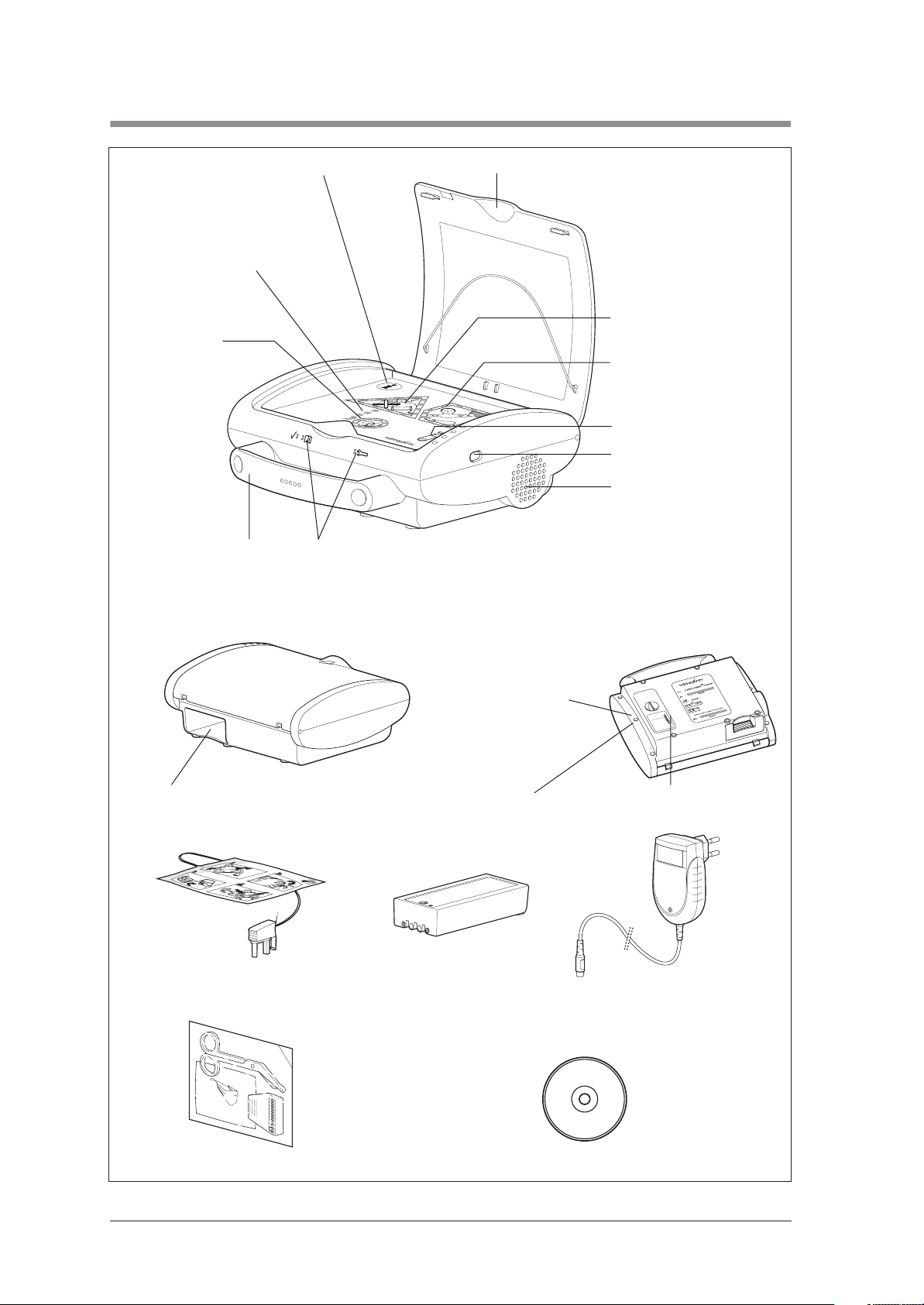
1. Overview
1 Info-button
11 Display:
Shock preperation
10 Shock key
9 Carrying handle
8 LEDs
2 Device lid
3 Display field: “Stand clear of
the patient!”
4 Display field: “You can now
touch the patient“
5 Socket for electrode plug
6 Infra red interface
7 Loudspeaker
Underside of device:
12 Battery compartment
16 Self sticking
defibrillation electrodes
Underside of device:
13 Maintenance sticker
14 SRC sticker
(only in Germany)
17 Battery-Pack/
Rechargeable
Battery-Pack
(optional)
18 Battery charger
15 Device plaque
(only in Rechargeable-Pack model)
4 Overview
19 Emergency set 20 CD-ROM with software EasyView
Page 5

2. Description of Equipment
2.1 Intended use
The MEDUCORE Easy is an automatic external
defibrillator (AED). It has been devised to assist the
user in the resuscitation of patients who show
symptoms of acute cardiovascular arrest (pulseless
ventricular tachycardia pVT or ventricular fibrillation
VF).
The MEDUCORE Easy guides the user through the
resuscitation process with the help of acoustic and
optical instructions. The device conducts an ECG
analysis on patients and, if necessary, makes
preparations for the delivery of an electric shock. The
delivery of a shock is carried out directly by the user,
after the device has prompted to do so.
Only use the device MEDUCORE Easy for the
purposes described below.
2.2 Scope of application
2.3 User qualification
The MEDUCORE Easy has been devised for
application in the heart/lung resuscitation (HLR) of
patients from upwards of 20 kg body weight at the
emergency’s location.
The MEDUCORE Easy may only be used by persons
who hold documented proof of the following
qualifications:
• Training in fundamental, life saving emergency
care including the application of automatic
defibrillators.
• Instructions for the application of the
MEDUCORE Easy carried out by an
WEINMANN authorized person.
Description of Equipment 5
Page 6

2.4 Functional description
The MEDUCORE Easy is compact, light and
ergonomic. The acoustic and optical user instructions
make the operation of the device, to a great extent,
self explanatory.
Persons with a nominal medical knowledge, after a
short instruction, can therefore be in the position to
operate a defibrillator in the case of a heart lung
resuscitation.
Optical and acoustic userguide The acoustic and optical user instructions are made up
of display fields and spoken orders.
After opening the device lid the user is led by
MEDUCORE Easy with the help of detailed spoken
orders through a step by step resuscitation process.
During this process a green and red display field light
up, indicating in which phase of the resuscitation the
patient may be touched or not touched (traffic light
principle).
Metronome function
(only for devices with ILCOR 2005)
An activated metronome function gives off an acoustic
metronome signal at a frequency of 100 beats per
minute during the HLR-pause. Carry out the cardiac
massage in rhythm with audible signal tone.
After 30 signal tones a spoken announcement is
issued “Give 2 breaths now” You will now have time
to carry out 2 respiratory sequences, before “Give 30
chest compressions now” is announced and 30 signal
tones are given.
This ordered sequence repeats itself, until the HLR
pause comes to an end and the red display field
(“Stand clear of the patient”) lights up.
If the info button is pressed during the HLR pause, the
info announcement is made. The metronome continues
to run in the background but without an audible tone.
ECG-recording and analysis As soon as the electrodes are placed on the bare
upper body of the patient, the device will
automatically begin with the recording and analysis of
the ECG. The ECG recording and analysis will
continue until the electrodes are removed from the
patient or as soon as the lid of the MEDUCORE Easy
is closed, which results in the device being switched
off.
6 Description of Equipment
Page 7

Defibrillation If the ECG analysis indicates defibrillation (pulseless
ventricular tachycardia pVT or ventricular fibrillation
VF), the MEDUCORE Easy prepares to deliver a
shock. Afterwards the device instructs the user to
administer a shock.
For other heart rhythms, the device informs the user that
they should carry out a heart-lung revival.
Application documentation The MEDUCORE Easy saves ECG and event data.
The data could later be used e.g. in the follow-up of
treatment. For this, use the documentation and
configurations software EasyView.
Self testing The MEDUCORE Easy initiates a self test at regular
intervals and after every time it is switched on. The
device status is shown via light diodes on its front side.
Self test results can be requested via the documentation
and configuration software EasyView and saved onto
a PC.
Description of Equipment 7
Page 8

3. Cleaning and disinfecting instructions
Warning!
• The Battery/Rechargeable Battery Pack must be
removed from MEDUCORE Easy before
cleaning.
• Never immerse the MEDUCORE Easy in any
disinfectant or any other liquid. Only carry out
disinfection by wiping over the surface. This can
otherwise lead to damage of the device and
consequently endanger users and patients.
The MEDUCORE Easy can be kept properly clean by
simply wiping to disinfect. Please observe the users
instruction for the disinfectant selected. We
recommend that you wear suitable gloves when
disinfecting the equipment (e.g. household or
disposable gloves).
We recommend that you use TERRALIN disinfectant,
which is available from the Schülke & Mayr
Company, Robert-Koch-Str. 2, D-22851 Norderstedt
(Internet: www.schuelkemayr.de).
8 Cleaning and disinfecting instructions
Page 9
4. Checking the device
Important!
The device must undergo the following tests after every
repair and every maintenance according to WM 40006,
and the results must be entered into the test records.
Additionally the test can be used for fault finding in the
device.
If you detect errors or deviations from defined values
in the course of your final testing you must not redeploy
MEDUCORE Easy before these errors have been
eliminated.
You can determine possible causes of such errors and
recommended countermeasures by referring to
chapter "7. Malfunctions and Rectification" on
page 22.
We recommend that you generally keep the following
ready for use:
• Emergency-Set WM 15460
• Battery-Pack WM 40155
• Rechargeable Battery-Pack WM 40150
4.1 Testing parts needed
• Electrodes, packed WM 40116
Important!
The electrodes have a limited shelf life. Please make a
note of the expiry date on the packaging.
• Fully charged Rechargeable battery Pack or
Battery-Pack
• Defibrillator-Tester (see also 10.4, page 38)
• IR-Adapter WM 22498
• PC with installed software EasyView WM 40192
• Multimeter, Measuring range up to 20 A
• Battery adapter WM 40008
• Test line MEDUCORE Easy WM 40454
Checking the device 9
Page 10
4.2 Preparations for testing
EasyView
EasyView-Service
1. Boot up PC.
2. Start the PC software.
Overview of software versions:
• EasyView
Reading, editing and saving usage data,
modifying device settings.
• EasyView-Service
Works like EasyView, facility for programming the
serial number.
• EasyView-Light
Works like EasyView; device settings cannot be
modified.
EasyView-Light
4.3 Entering the device data
Enter the serial number of the device (Device-No.) and
the manufacturing date into the test records.
4.4 Checking the devices self testing
1. Insert rechargeable or Battery-Pack.
2. Open the device lid.
3. Close the device lid.
Request:
– The device is giving off a short double peeping
tone.
– All LEDs light up briefly.
– The device announces clearly and completely
the spoken order “This device will assist you.”.
– The green status LED lights up.
10 Checking the device
Page 11
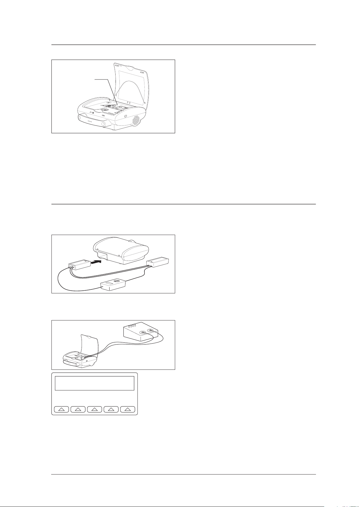
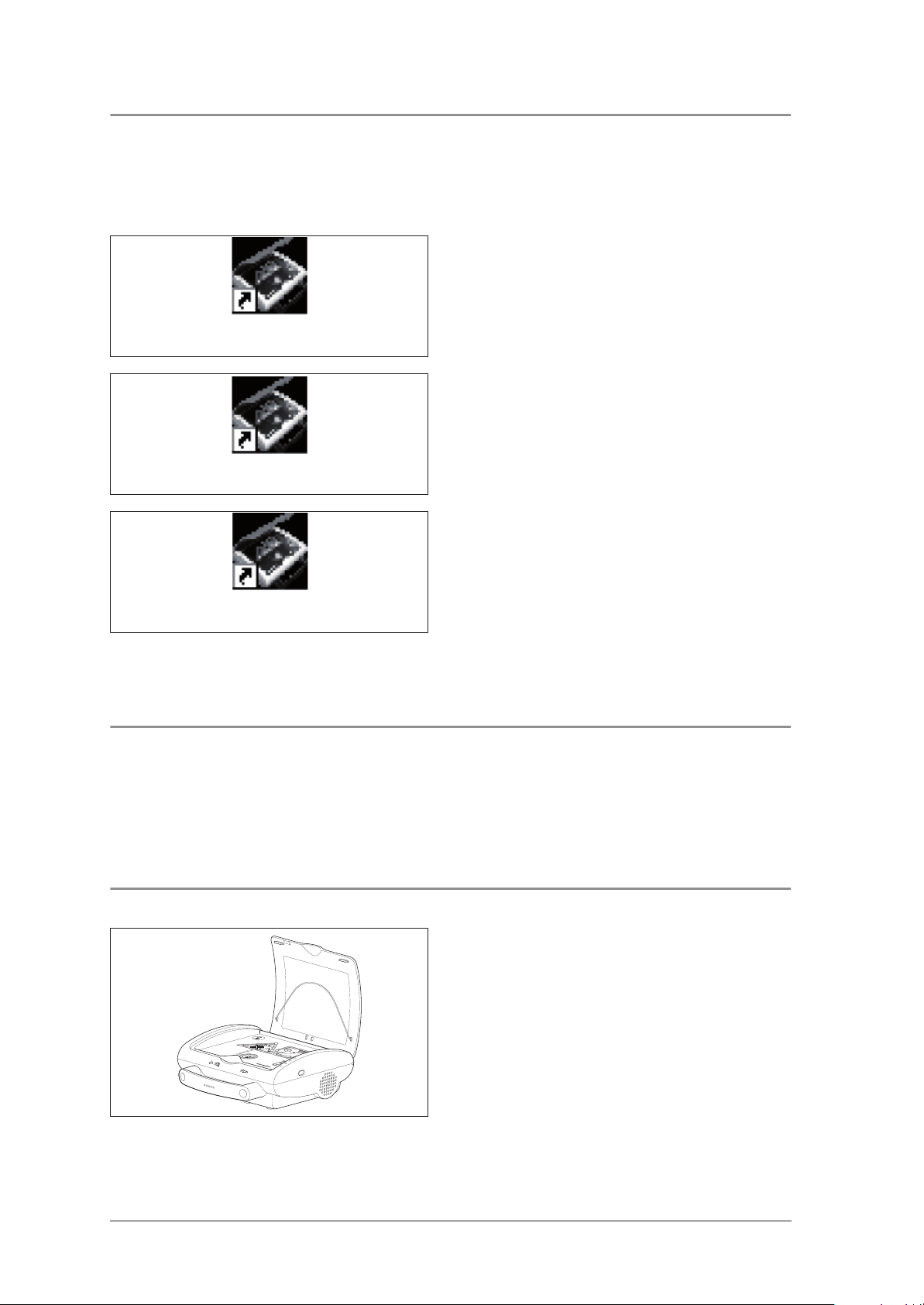
4.5 Checking the volume levels
1. Ensure that the volume setting is on "automatic". To
do so, connect the device to EasyView and cor-
Microphone
rect the setting if necessary.
2. Open the device lid.
3. Create a sound directly over the microphone of
the MEDUCORE Easy, by scratching on the encasing for example.
The microphone in the MEDUCORE Easy can be
found between the analysis triangle and pentagon.
Request:
– The volume of the repeated and clearly spoken
order increases.
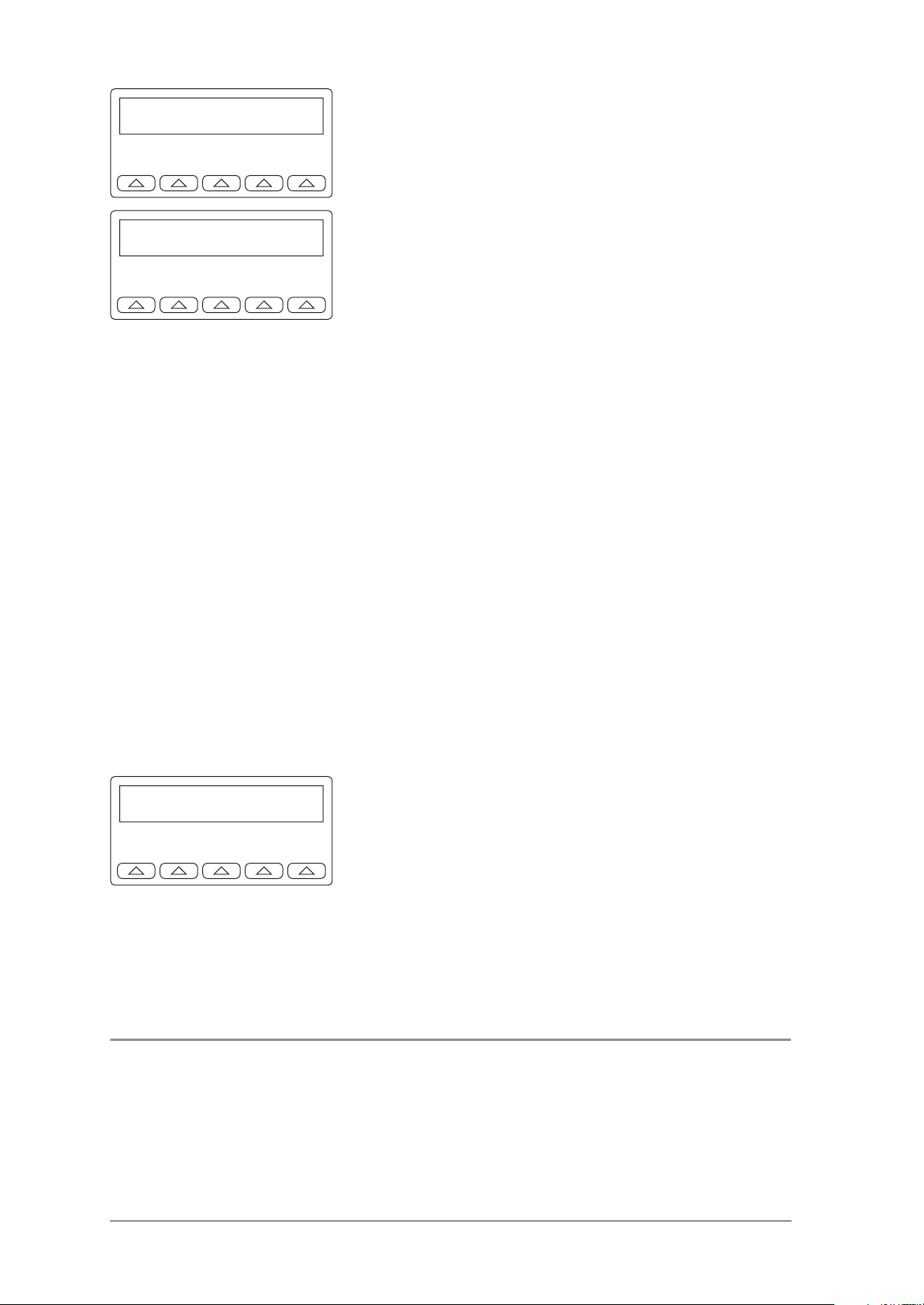
4.6 Testing the ECG detection, current input, shock button and shock output
Preparation of the MEDUCORE Easy
1. Connect the rechargeable battery adapter, current measuring device and rechargeable battery
or battery pack as illustrated.
2. Install the rechargeable battery adapter in the
MEDUCORE Easy.
Preparation of the defibrillator tester The defibrillator tester emulates a patient impedance
of 50 Ω.
1. Connect MEDUCORE Easy test line WM 40454
to the defibrillator tester as illustrated.
2. Connect the defibrillator tester to a power supply
(battery or mains plug).
3. Switch on the defibrillator tester (sliding switch
POWER in position I).
ENRG SYNC PEAK WAVE more
Main Menu 1
A self-test is performed. The main menu appears
in the display (Main Menu 1).
Checking the device 11
Page 12
Energy --- J
WAV> ECG90 PLAY HDR esc
4. Press the arrow button under ENERG.
The indicator for the Energy Modus appears in the
display.
Energy --- J
WAV> VFIB PLAY HDR esc
button under WAV until VFIB appears in the
display.
Performing the test 1. Open the lid of the device.
2. Plug the defibrillator tester electrode plug into the
device.
Requirement:
– The device detects ventricular fibrillation and
after a maximum of 10 sec clearly gives the
spoken message "Shock required".
3. The device prepares to give the shock.
Requirement:
– The current consumption of the device is be-
tween 6 A and 12 A.
4. Note the current consumption in the test report.
5. After the spoken message: "Press the flashing
shock key", activate this.
Requirement:
– The shock is triggered by activation of the
shock button.
– The shock is given. The device clearly gives the
spoken message "Shock was delivered".
5. To simulate venticular fibrillation: Press the arrow
Energy 162 J
WAV> VFIB PLAY HDR esc
– The energy discharged is between
168 J ± 10 % (Low Energy). The value is
shown in the display of the defibrillator tester.
Note:
Only the testing of the "Low Energy" shock is necessary.
If it is also required to test the "High Energy", the energy
must be 298 J ± 10 %.
In this case, ventricular fibrillation must be set on the
defibrillator tester as described above. Return to the main
menu via esc.
4.7 Checking the procedure display and capacitor discharge
Note:
Do not press the shock key during this test!
1. Simulate ventricular fibrillation with the defibrillator-tester (Signal Vfib).
12 Checking the device
Page 13
2. The device makes a clear spoken order “Stand
clear of the patient” and “Analyzing”.
Request:
– All of the LEDs in the red triangle light up.
– The device continues to give spoken orders,
during which all the LEDs on the shock key
arrow are lit up in red.
– All of the LEDs around the shock key flash red.
3. After approx. 15 seconds it is announced that
“Shock was not delivered”.
Request:
– The capacitor is discharged with an audible
sound.
4. Simulate f = 60 bpm with the defibrillator-tester
Sinus EKG.
Request:
– All of the LEDs in the green pentagon light up.
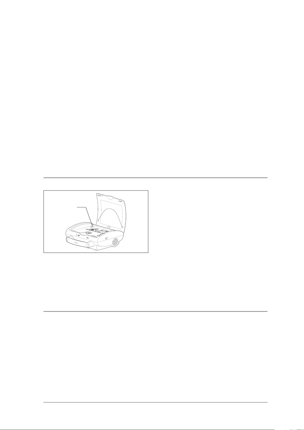
4.8 Checking the info-button and reading contact
Info-button
4.9 Checking the status LEDs
1. While the green pentagon is lit up, press the infobutton.
Request:
– The device announces a spoken order similar
to “Device has been in use for…in total
1 shock since device startup”.
2. Pull the electrode plug out of the device.
3. Close the device lid.
Request:
– The device cuts short any spoken order,
extinguishes all process LED lights and leaves
only the green status LED blinking.
– No new spoken order is made.
Open the device lid to turn the device on.
Request:
– All of the three Status-LEDs, (red, green, yellow)
light up.
Checking the device 13
Page 14
4.10 Checking the condition of the exterior, the equipment and the accessories
1. Firstly, carry out a visual test of everything.
Requests:
• Encasing
– Encasing not scratched and without blemishes
– Encasing completely screwed on
– Front film and sticker stuck down firmly and
correctly on the lid
– Labelling OK?
– The loudspeaker opening is free from dirt.
• Electrode connection
– Undamaged
– In working order
• Push buttons
– Undamaged
– Working correctly
• Lid
– Lid not scratched and without blemishes
– Lid is correctly attached, easy to open and
closes firmly
– Functions open, close, switch on are ok.
• Inner part
– The socket for the electrode plug is free from
dirt.
• Rechargeable Battery-Pack
– Completely charged
• Battery-Pack
– Check expiry date (see device sign Battery-
Pack). Insert new Battery-Pack if necessary.
– If the expiry date is not yet reached, then check
the level of charging. Insert battery, open and
close device lid. The green LED must flash; the
yellow LED should not flash.
If these parts have been delivered, check:
14 Checking the device
• Defibrillation electrodes WM 40116 available.
Check expiry date, if necessary replace.
• Rechargeable Battery-Pack WM 40150
available.
• Battery-Pack WM 40155 available.
• Emergency set WM 15460 available.
Page 15
4.11 Checking the IRDA interface and the software version
1. Check that the interface is working correctly by
retrieving the device data.
Request:
All the device data are displayed.
2. Ensure that a PCB with the latest device software
is installed in the device. This can be done by
comparing the software version displayed with
table (see "12.2 Software" on page 43).
If the software version is no longer current, replace
the PCB with an up-to-date one as described in
section 8.9 and enter the device number as
described.
4.12 Checking the maintenance and safety related check (SRC) stickers
Check that the maintenance and SRC stickers are
affixed correctly (SRC sticker applies only to
Germany). If repairs have been carried out, then you
should replace the stickers with new ones.
4.13 Preparing a device for dispatch following repair
Conditions The Programme EasyView must be started up and
the PC infrared interface or the infrared adapter
must be aligned with the infrared interface of the
MEDUCORE Easy (see chapter “Operation” in
the PC-software operating instructions EasyView
WM 16880).
Execution 1. Insert Rechargeable Battery or Battery-Pack.
2. Open the device lid.
3. Read off the charge status of the battery pack and
compare it with the value specified in the test
record.
Depending on the Battery-Pack capacity
displayed proceed as follows:
• Capacity is > 50%:
– The Battery-Pack is OK.
• Capacity is < 50%:
– Inform your customer about the charging
level.
Checking the device 15
Page 16

– Recommend that your customer regularly
checks the charging level.
– Recommend that your customer replaces the
Battery-Pack in good time.
• Capacity is < 15%:
– Inform your customer about the charging
level.
– Recommend that your customer regularly
checks the charging level.
– Offer your customer a new Battery-Pack.
– Recommend that your customer replaces the
Battery-Pack as soon as possible.
• Capacity is < 8%:
– Inform your customer about the charging
level.
– Offer your customer a new Battery-Pack.
– Point out to your customer that the Battery-
Pack should be replaced immediately for
safety reasons.
4. Set the date and time with the help of the
EasyView (see chapter “Operation“ in the operating instructions for the PC-Software EasyView
WM 16880).
After exchanging the printed circuit
board, if no customer parameter are
known 1. Delete the memory.
2. Enter serial number (Device-No.) (see "4.3 Entering the device data" on page 10).
After exchanging the printed circuit
board, if customer parameter are
known 1. Programme customer parameter.
2. Delete the memory.
3. Check the selected language version.
Request:
– EasyView-Service must display the selected
language version without any error messages.
Note:
To continue testing, the volume must be set to
"automatic".
Completion 1. Close the device lid.
2. Remove Rechargeable Battery or Battery-Pack
16 Checking the device
3. To unload the internal remaining charge, open
and close the device lid again.
Page 17

4.14 Documentation
Note down the points 4.3 to 4.12 as well as the test
date and tester number in the test records.
Checking the device 17
Page 18

5. Maintenance
5.1 Intervals
Note:
After all maintenance and repair work the device must be
tested, as described in chapter „4. Checking the
device“on page 9.
As a preventative maintenance measure every 6 years
the device must be fully checked:
The points of maintenance are as follows:
• Testing for completeness (see chapter 4.10,
page 14)
• Visual test (see chapter 4.10, page 14)
– Mechanical damage
– Electrode connections
– Labelling
• Check the charge levels on the Battery/
Rechargeable Battery (see chapter 5.2, page 18)
• Replace internal battery (see chapter 8.8,
page 29)
• Final check in accordance with test directive
WM 40006 (see chapter 4., page 9)
• Renew maintenance sticker
In Germany a safety related check (SRC) must be
conducted within a statutory limit of 2 years in
accordance with §6 Medicinal Products and Users
Ordinance.
5.2 Check the Battery/Rechargeable Battery.
Conditions The Programme EasyView must be started up and
the PC infrared interface or the infrared adapter
must be aligned with the infrared interface of the
MEDUCORE Easy (see chapter ”Operation“ in
the PC-software operating instructions EasyView
WM 16880).
18 Maintenance
Page 19

Execution 1. Insert Rechargeable Battery or Battery-Pack
2. Open the device lid.
3. Read off the level of charge of the Battery-Pack
and note in the test records.
Depending on the Battery-Pack capacity
displayed proceed as follows:
• Capacity is > 50%:
– The Battery-Pack is OK.
• Capacity is < 50%:
– Inform your customer about the charging
level.
– Recommend that your customer regularly
checks the charging level.
– Recommend that your customer replaces the
Battery-Pack in good time.
• Capacity is < 15%:
– Inform your customer about the charging
level.
– Recommend that your customer regularly
checks the charging level.
– Offer your customer a new Battery-Pack.
– Recommend that your customer replaces the
Battery-Pack as soon as possible.
5.3 Renew maintenance sticker
Maintenance sticker
• Capacity is < 8%:
– Inform your customer about the charging
level.
– Offer your customer a new Battery-Pack.
– Point out to your customer that the Battery-
Pack should be replaced immediately for
safety reasons.
If required, replace the Battery or charge
Rechargeable Battery
Renew the maintenance sticker (current year
+ 6 years) sticking it to the underside of the device.
• Replace the old maintenance sticker with one
carrying the newly entered data. Cut out the
correct month using a ticket puncher or the point
of some nail scissors. Stick the new maintenance
sticker on the underside of the device.
Maintenance 19
Page 20

5.4 Disposal
Device
Do not dispose of the device as domestic waste. To
dispose of the device properly, please contact a
licensed and certified electronic waste recycler.
Names and addresses can be obtained from your
Environmental Officer or municipal authorities.
Disposal of batteries
Do not dispose of spent batteries in the domestic
waste. Please either contact WEINMANN or or your
official local public disposal authorities.
20 Maintenance
Page 21

6. Safety related check according to §6 Medicinal products and Users ordinance
6.1 General
Important!
Performance of a safety related check [SRC] in
accordance with §6 of the German Medicinal products
and Users ordinance [MedizinprodukteBetreiberverordnung] is only mandatory in Germany.
6.2 Execution
Safety related checks follow the same steps as
described in chapter "4. Checking the device" on
page 9.
The following is only an additional description of the
required steps to be taken.
6.3 Testing devices
6.4 Replace SRC sticker
SRC sticker
6.5 Documentation
Additional to the named testing devices described in
chapter 4.1 you will need:
• SRC protocol (see " WM 40007f, page 2" on
page 46)
If you have carried out a safety related check, a new
SRC sticker (current year + 2 years) has to be stuck to
the underside of the device.
• Replace the SRC sticker with a new one with the
correct dates. Cut out the correct month using a
hole puncher or the point of some nail scissors.
Stick the new SRC sticker next to the maintenance
sticker on the underside of the device.
• Fill out the SRC protocol.
• Prepare an SRC certificate for the customer.
Safety related check according to §6 Medicinal products and Users ordinance 21
Page 22

7. Malfunctions and Rectification
Malfunctions Cause Rectification
In stand by mode (lid closed) a
signal tone is set off every four
minutes.
A malfunction has been
established while the device
underwent the monthly/daily self
tests.
Battery capacity is exhausted.
Check which LED blinks and the
procedure, according to the
respective LED described in the
following table.
Insert new Battery/Rechargeable
Battery Pack (see chapter „Energy
Supply“ in the operating
instructions MEDUCORE Easy).
When the lid is open the device
can not turn on.
Upon opening the lid the
following message can be heard:
“Device is not ready for use”
Upon opening the lid the
following message can be heard:
“Battery is low”
The red LED will light up (flashing
when on stand by and constant
when in operation).
Damaged connection between the
energy supply contacts and main
circuit board
Main circuit board defective.
Battery power levels are low.
If the battery power levels are low
then fewer than 3 shocks can be
delivered.
Device is not ready for operation,
self test has detected a
malfunction.
Opening device and checking
connections (Chapter 8.3,
Page 25).
Open up device and replace the
main circuit board (Chapter 8.9,
Page 30).
Device messages with EasyView
voice prompting. If EasyView
“Malfunction in the main circuit
board” is displayed, then replace
the main circuit board
(Chapter 8.9, Page 30).
Finish off current treatment and
then replace batteries (see
Chapter “Energy Supply” in the
operating instructions
MEDUCORE Easy).
Replace battery (see Chapter
“Energy Supply” in the operating
instructions of the
MEDUCORE Easy), to enable
continued treatment.
Finish off current treatment. Then
read out malfunction protocol via
the EasyView. If EasyView
“Malfunction in the main circuit
board” is displayed, then
exchange main circuit board
(Chapter 8.9, Page 30).
The green and yellow LEDs light
up (flashing when on stand by
and constant when in operation).
The yellow LEDs light up (flashing
when on stand by and constant
when in operation).
22 Malfunctions and Rectification
The battery/rechargeable battery
power levels are low and barely
10/6 shocks can still be
delivered.
A less critical malfunction has
been detected, e.g. time is
incorrect.
Finish off current treatment and
then replace batteries (see
Chapter “Energy Supply” in the
operating instructions
MEDUCORE Easy).
Finish off current treatment. Then
read out malfunction protocol via
the EasyView and if necessary
correct malfunction e.g. reset
clock.
Page 23

Malfunctions Cause Rectification
After switching device on, one or
more LEDs/display fields do not
light up briefly.
Spoken command: “Attach
electrodes to bare chest!“ repeats
itself even though electrodes have
been stuck down.
Shocks can not be delivered, in
spite of flashing shock key.
Spoken command “Movement
detected. Stand clear of the
patient!” is made.
One or more of the status LEDs/
display fields is defective.
RTC battery empty.
Electrode plug is not correctly
plugged in.
Electrodes not correctly stuck
down.
Electrodes touching each other.
Electrodes defective
Wrong electrodes
Damaged connection between the
electrode contacts and main
circuit board
Main circuit board defective.
Main circuit board defective.
MEDUCORE Easy recognises
artefact and carries out a new
analysis.
Finish off current treatment, and
then replace the main circuit
board (Chapter 8.9, Page 30).
Replace Real Time Clock batteries
(Chapter 8.8, Page 29).
Insert plug correctly.
Press the electrodes directly down
onto dry, and if necessary shaved
skin.
Check the positioning of the
electrodes.
Replace electrodes, otherwise do
not attempt to operate device.
Only use genuine WEINMANNelectrodes.
Open device and check
connections (Chapter 8.3,
Page 25).
Open up device and exchange
the main circuit board
(Chapter 8.9, Page 30).
Open up device and exchange
the main circuit board
(Chapter 8.9, Page 30).
Do not touch or move the patient
during the analysis.
Green status LED does not flash
when the lid has been closed.
No automatic self test is carried
out.
Time and date entries, after
switching the device off and on
again, display a default value.
Rechargeable Battery or BatteryPack is drained.
LED is defective
RTC battery empty.
RTC battery empty.
Insert new Battery/Rechargeable
Battery Pack (see Chapter “Energy
Supply” in the operating
instructions MEDUCORE Easy).
Open up device and replace the
main circuit board (Chapter 8.9,
Page 30).
Replace Real Time Clock batteries
(Chapter 8.8, Page 29).
Replace Real Time Clock batteries
(Chapter 8.8, Page 29).
Malfunctions and Rectification 23
Page 24

8. Repair information and repair instructions
8.1 General
• Please perform repairs on MEDUCORE Easy only on
an ESD work station!
• Refer to the safety instructions in the operating
manuals for MEDUCORE Easy.
• Any handling of this device requires in-depth
knowledge of and adherence to the operating
manual and the maintenance and repair manual.
• Perform only the repairs as described in this
maintenance and repair manual. This is the only
way to ensure that the MEDUCORE Easy
operates properly.
• Make sure that your hands and your workspace
are clean when performing repairs.
• After every repair a maintenance check must be
performed (see "4. Checking the device" on
page 9).
• When replacing components or single parts, use
only genuine WEINMANN Parts.
• When ordering the device’s lower encasing 25
you have to state the device type, year of
manufacture and serial number.
Note:
The item numbers stated in the following text are identical
to the item numbers of the spare part list on page 34 and
the overview on page 4.
8.2 Tools and facilities
24 Repair information and repair instructions
In order to perform the repairs described in this
chapter, you will need the following tools and
facilities:
• Phillips screwdriver size: PZ 2
• Nail scissors or ticket-punch to mark the
maintenance plaque
• Pincers
• High-voltage protected needle nose pliers
• ESD Workstation
• Discharging device WM 40009
or:
protected high-voltage workstation
Page 25

Danger of death! Danger of electric shock! If no discharging unit is available, work on the MEDUCORE Easy must
be carried out at a protected high-voltage workstation.
Before carrying out any repair, it is essential to discharge
the capacitor as described in Section “8.3 Discharge high
voltage capacitor and open up device” on page 25, otherwise fatal injuries may be sustained.
8.3 Discharge high voltage capacitor and open up device
Preparation
Danger! Risk of electric shock!
If a malfunction occurs in the device during a functional
check, then it may not be used.
1. Remove the Battery-Pack/Rechargeable Battery
Pack from the battery compartment
MEDUCORE Easy.
2. Lie the MEDUCORE Easy with the red lid facing
down on a non-slip surface.
30 33
3. Remove the sealing plugs 33.
4. Loosen and remove the ten screws 30.
5. Take the MEDUCORE Easy in both hands and
hold both encasing elements together. Lie the
MEDUCORE Easy with the red lid facing upward
in the discharging device.
6. Close the discharging device lid.
7. Pull back the contact rocker of the discharge device and swing it upwards.
Discharging process 1. Slide the locking element back to release the
lifting aid.
2. Press the bellows together and place the suction
pad far left of the middle on the red lid of the
MEDUCORE Easy.
3. Release the bellows. The suction pad will fasten
itself.
4. Pull the lifting aid upwards. This serves to lift the
upper part of the encasing.
5. Slide the locking element forwards to hold the
lifting aid up and in so doing also the upper part
of the encasing.
Repair information and repair instructions 25
Page 26

6. Slide the contact rocker into its resting position.
7. Check to see that the contact pin is directly above
the capacitor contacts.
If necessary, make some fine settings using the
black screw on the front of the carriage.
8. Flip down the contact rocker. The contact pin must
now be touching the capacitor contacts on the
printed circuit board.
The capacitor is then completely discharged. The
discharging process lasts approx. 4 seconds. It is
completed when -0.00 is displayed.
To be certain that the capacitor is discharged, carry
out the following tests:
9. Press the red button on the front of the device.
– The capacitor is very slightly charged. The
display will now show for example 0.07.
– Upon releasing the button the display must
slowly return to -0.00 .
Danger! Risk of electric shock!
If the display returns immediately to -0.00 then the
contact pin is no longer in contact with the capacitor
contact on the printed circuit board. The capacitor has in
this case not been discharged. Adjust the position of the
contact pin and check it again.
Completion 1. Pull the contact rocker back.
2. Slide the locking element back to release the
lifting aid.
3. Lower the upper part of the encasing.
4. Rotate the lifting aid to release the suction pad
from the lid.
5. Open the protective cover of the device and
remove the MEDUCORE Easy.
6. Switch the discharging device via the rocker
switch off.
7. Close the device (8.6, page 28).
26 Repair information and repair instructions
Page 27

8.4 Opening the device
21
22
24
25
Danger of death! Danger of electric shock! If no discharging unit is available, work on the MEDUCORE Easy must
be carried out at a protected high-voltage workstation.
1. Take the red device lid 2 off.
2
2. Remove the pins 21 and springs 22 and store them
in a safe place.
3. Lie the MEDUCORE Easy with the upper
encasing 24 facing down on a non-slip surface.
4. Carefully open the lower encasing device 25.
5. Pull the loudspeaker cable from the printed circuit
board.
6. Pull the red cable plug out of the printed circuit
board.
7. Pull the capacitor out of the lower encasing part
and place it carefully on the main circuit board.
8. Pull the plug belonging to the pad cable 40 and
40
41 out of the printed circuit board.
9. Pull the blue and black cable plugs out of printed
circuit board.
10. Now you can set aside the lower encasing part 25.
40
24
8.5 Exchange the device lids
Remove lid 1. Open the red device lid 2.
2. Slide the pins 21 out to one side and remove
21
2
22
them.
3. Pull the springs 22 out and store them in a safe
place.
4. Take the device lid 2 off.
Repair information and repair instructions 27
Page 28

Fitting lid 1. Place the ends of the springs 22 into the prepared
holes of a new device lid.
2. Slide the pins 21 from the side far enough into the
lid, so that the springs 22 are held in place.
3. Replace the lid 2, so that the other end of the
springs are situated between the encasing halves.
4. Slide the pins 21right in.
5. Close the device lid.
8.6 Close the device
30 33
1. Hold the lower encasing part 25 up to the upper
encasing part 24.
2. Plug the blue cable into the printed circuit board
(Labelled HDQ).
3. Plug the black cable into the printed circuit board
(Labelled ACCU -).
4. Take the pad plug cable 40 and 41 and plug it
into the printed circuit board.
5. Press the capacitor into the compartment of the
lower encasing part. Guide the cable in through
the slit.
6. Plug the cables for capacitor 27 onto the board.
Ensure that polarity +/- is correct (see labeling on the
board and on the capacitor)! If the cables are the
wrong way round, the top and bottom parts of the
device will not fit together properly.
7. Plug the red cable into the printed circuit board
(Labelled ACCU + ).
8. Plug the speaker cable into the printed circuit
board.
9. Place the lower encasing part 25 onto the upper
encasing part 24.
Please make sure that the cables do not get clamped.
10. Now screw the upper encasing part tightly with
the ten screws 30 .
11. Set the sealing plugs 33 in place.
12. Turn the device around the right way again and
fit the lid (see "8.5 Exchange the device lids" on
page 27).
13. Check the device (see "4. Checking the device"
on page 9).
28 Repair information and repair instructions
Page 29

8.7 Exchanging the capacitor
27
Danger of death! Danger of electric shock! The condenser
must be completely discharged (see Chapter "8.3",
Page 25).
1. Discharge the capacitor and open the device (see
Chapter "8.3", Page 25).
2. Pull the capacitor cable 27 out of the printed
circuit board with the aid of high-voltage
protected needle nose pliers.
3. Remove the capacitor 27 and dispose of it (see
Chapter "5.4", Page 20).
4. Place a new capacitor onto the printed circuit
board. Make sure that insulation mats 28 are lying
between the capacitor and the main circuit board.
5. Plug the capacitor cable 27 into the printed circuit
board. Make sure that the polarity is correct +/- (see the
labelling on the printed circuit board and on the
capacitor)! If the cables are mixed up then the upper and
lower device parts will not fit to each other correctly.
6. Close the device (see Chapter "8.6", Page 28).
8.8 Replace the Real Time Clock batteries
Danger of death! Danger of electric shock! The condenser
must be completely discharged (see Chapter "8.3",
Page 25).
1. Discharge the capacitor and open the device (see
Chapter "8.3", Page 25).
34
2. Push the springs slightly backwards and remove
the battery 34.
3. Replace with new (button cell CR2032) battery.
Make sure that the polarity is correct!
4. Close the device (see Chapter "8.6", Page 28).
5. Set the date and time with the help of EasyView
(see chapter “Operation” in the operations
manual for PC software EasyView WM 16880).
Repair information and repair instructions 29
Page 30

8.9 Replacing the main circuit board
Danger of death! Danger of electric shock! The condenser
must be completely discharged (see Chapter "8.3",
Page 25).
1. Discharge the capacitor and open up the device
(see "8.3 Discharge high voltage capacitor
and open up device" on page 25).
Remove the main circuit board 1. Pull the capacitor cable 27 out of the circuit
board.
26
27
2. Remove the capacitor 27.
3. Lever the main circuit board 26 out.
Inserting the main circuit board 1. Insert a new main printed circuit board 26 in
place. Make sure that the capacitor buffer 29 is
jutting out of the main circuit board.
2. Place the capacitor onto the printed circuit board.
Make sure that insulation mats 28 are lying between
the capacitor and the main circuit board.
3. Plug the capacitor cable 27 into the printed circuit
board. Make sure that the polarity is correct +/- (see
the labelling on the printed circuit board and on the
capacitor)! If the cables are mixed up then the upper
and lower device parts will not fit to each other
correctly.
4. Close the device (see Chapter "8.6", Page 28).
Program the serial number on new main
circuit board To change the serial number on the main circuit board
in MEDUCORE Easy you will require the EasyViewService software (see Chapter "4.2", Page 10).
Note:
Remember that the serial number entered can be 4
or 5 characters, and can only consist of the numbers
0 to 9!
30 Repair information and repair instructions
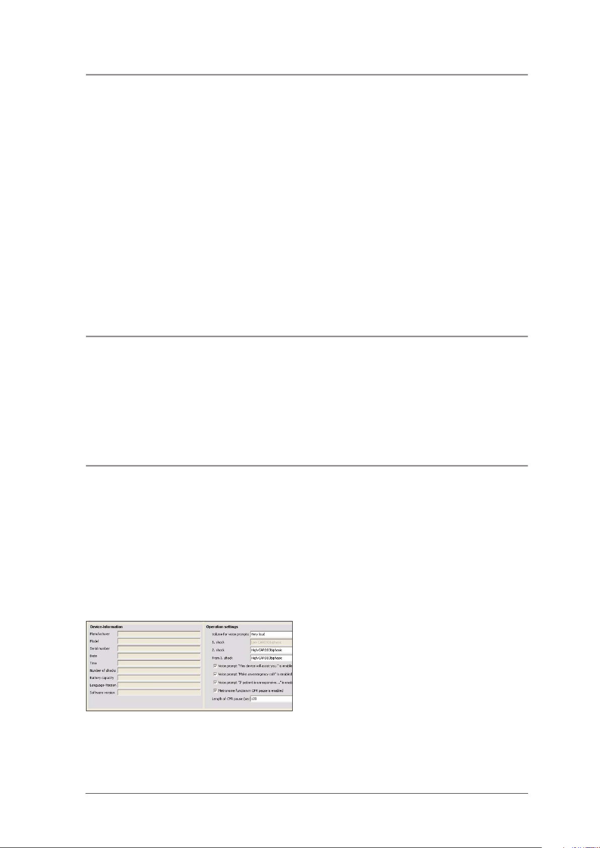
1. Start the EasyView-Service software and choose
the "Device settings" tab.
Page 31

Click the "Get device settings" button.
The device configuration will be displayed.
2. Enter the device's 5-digit serial number. Then click
the "Print settings" button.
3. Next, confirm the change to the device
configuration. The number will now be stored in
MEDUCORE Easy.
If a 4-digit serial number is entered, the system will
automatically pad it out to 5 digits by adding a
leading "0".
If the serial number was entered successfully, the
following message will appear: "Communication
successful".
If you have entered a serial number with less than 4
(or more than 5) digits, the following message will
appear: "Serial number must have 4 or 5 digits".
Repair information and repair instructions 31
Page 32

8.10 Exchanging pad plug cable
41
40
43 42
Repeat the process with a number of the correct
length.
This concludes the programming of the serial number.
Danger of death! Danger of electric shock! The condenser
must be completely discharged (see Chapter "8.3",
Page 25).
1. Discharge capacitor and open up the device (see
"8.3 Discharge high voltage capacitor
and open up device" on page 25).
2. Loosen the nuts 43 and take the spring washer 42
off.
3. Pull the plug belonging to the cable 40 and 41 out
of the printed circuit board.
4. Plug the new cable in its place.
5. Place the cable lug and spring washer onto the
screw and screw the nut onto it. Make sure that the
order is correct!
6. Close the device (see Chapter "8.6", Page 28).
8.11 Exchanging the speaker
Removing the speaker
47
46
44
45
Danger of death! Danger of electric shock! The condenser
must be completely discharged (see Chapter "8.3",
Page 25).
1. Discharge capacitor and open up the device (see
"8.3 Discharge high voltage capacitor
and open up device" on page 25).
2. In the lower encasing part: Rotate the screw out of
the wedge 47 .
3. Pull the wedge 46 out.
4. Remove the loudspeaker 44 together with the
seal 45.
Dispose of the old seal and the old wedge,
together with the defective loudspeaker.
32 Repair information and repair instructions
Page 33

Fitting speaker 1. Use only parts from spare parts set WM 15705.
2. Take new seal 45 from the spare parts set and put
it on the new loudspeaker.
3. Place the new speaker into the device. Make
certain the seal is well fitted and flush.
4. Put the wedge into its position and screw it in
tightly.
5. Close the device (see Chapter "8.6", Page 28).
8.12 Exchange encasing, upper part
Danger of death! Danger of electric shock! The condenser
must be completely discharged (see Chapter "8.3",
Page 25).
1. Discharge capacitor and open up the device (see
Chapter "8.3", Page 25).
2. Remove the main circuit board (see Chapter
"8.9", Page 30).
3. Install the main circuit board into a new upper
encasing part 24 (see Chapter "8.9", Page 30).
4. Close the device (see Chapter "8.6", Page 28).
8.13 Exchanging encasing, lower part
Danger of death! Danger of electric shock! The condenser
must be completely discharged (see Chapter "8.3",
Page 25).
1. Discharge capacitor and open up the device (see
Chapter "8.3", Page 25).
2. Remove the handle from the old lower encasing
part and fit it to the new lower encasing part 25
(see operating instructions “Fitting accessories“).
3. Close the device (see Chapter "8.6", Page 28).
Repair information and repair instructions 33
Page 34

9. Replacement parts
Note:
The item numbers of the following table are identical to the numbers used in the body of text of this service
and maintenance manual.
Item-No. Name Ordering-No.
Lid, complete DE
Lid, complete GB
Lid, complete FR
Lid, complete IT
Lid, complete TH
Lid, complete JP
Lid, complete NO
Lid, complete SE
Lid, complete DK
Lid, complete RU
Lid, complete PL
Lid, complete NL
2
Lid, complete ES
Lid, complete PT
Lid, complete FI
Lid, complete IS
Lid, complete TR
Lid, complete CZ
Lid, complete GR
Lid, complete SI
Lid, complete SK
Lid, complete HR
Lid, complete ID
Lid, complete CN
Lid, complete IR
WM 40125
WM 40337
WM 40347
WM 40357
WM 40367
WM 40377
WM 40387
WM 40397
WM 40407
WM 40417
WM 40427
WM 40437
WM 40447
WM 40457
WM 40467
WM 40477
WM 40487
WM 40497
WM 40507
WM 40517
WM 40527
WM 40667
WM 40677
WM 40687
WM 40558
16
Defibrillation electrodes DE GB
Defibrillation electrodes FR
Defibrillation electrodes IT
Defibrillation electrodes TH
Defibrillation electrodes JP
Defibrillation electrodes NO
Defibrillation electrodes SE
Defibrillation electrodes DK
Defibrillation electrodes RU
Defibrillation electrodes PL
Defibrillation electrodes NL
Defibrillation electrodes ES
Defibrillation electrodes PT
Defibrillation electrodes FI
Defibrillation electrodes IS
Defibrillation electrodes TR
Defibrillation electrodes CZ
Defibrillation electrodes GR
Defibrillation electrodes SI
Defibrillation electrodes SK
Defibrillation electrodes HR
Defibrillation electrodes ID
Defibrillation electrodes CN
Defibrillation electrodes IR
WM 40116
WM 40349
WM 40359
WM 40369
WM 40379
WM 40389
WM 40399
WM 40409
WM 40419
WM 40429
WM 40439
WM 40449
WM 40459
WM 40469
WM 40479
WM 40489
WM 40499
WM 40509
WM 40519
WM 40529
WM 40439
WM 40019
WM 40069
WM 40468
34 Replacement parts
Page 35

Item-No. Name Ordering-No.
17
18 Battery charger WM 40003
19 Set, Emergency MEDUCORE Easy WM 15460
20 PC-Software EasyView WM 40192
Battery-Pack
Rechargeable Battery-Pack
WM 40155
WM 40150
21 Hinge pin WM 40123
22 Spring for lid WM 40124
23 Retaining bracket WM 40024
24 Encasing, upper part, preassembled WM 40076
25 Encasing, lower part, assembled* WM 40002
26
Main circuit board DE, new
Main circuit board DE, replacement
Main circuit board GB, new
Main circuit board GB, replacement
Main circuit board FR, new
Main circuit board FR, replacement
Main circuit board IT, new
Main circuit board IT, replacement
Main circuit board TH, new
Main circuit board TH, replacement
Main circuit board JP, new
Main circuit board JP, replacement
Main circuit board NO, new
Main circuit board NO, replacement
Main circuit board SE, new
Main circuit board SE, replacement
Main circuit board DK, new
Main circuit board DK, replacement
Main circuit board RU, new
Main circuit board RU, replacement
Main circuit board PL, new
Main circuit board PL, replacement
Main circuit board NL, new
Main circuit board NL, replacement
Main circuit board ES, new
Main circuit board ES, replacement
Main circuit board PT, new
Main circuit board PT, replacement
Main circuit board FI, new
Main circuit board FI, replacement
Main circuit board, IS, new
Main circuit board, IS, replacement
Main circuit board TR, new
Main circuit board TR, replacement
Main circuit board CZ, new
Main circuit board CZ, replacement
Main circuit board GR, new
Main circuit board GR, replacement
Main circuit board SI, new
Main circuit board SI, replacement
Main circuit board SK, new
Main circuit board SK, replacement
WM 40130
WM 40063
WM 40330
WM 40313
WM 40340
WM 40343
WM 40350
WM 40353
WM 40360
WM 40363
WM 40370
WM 40373
WM 40380
WM 40383
WM 40390
WM 40393
WM 40400
WM 40403
WM 40410
WM 40413
WM 40420
WM 40423
WM 40430
WM 40433
WM 40440
WM 40443
WM 40450
WM 40453
WM 40228
WM 40483
WM 40368
WM 40023
WM 40244
WM 40493
WM 40258
WM 40503
WM 40375
WM 40193
WM 40268
WM 40203
WM 40378
WM 40243
Replacement parts 35
Page 36

Item-No. Name Ordering-No.
26
Main circuit board HR, new
Main circuit board HR, replacement
Main circuit board ID, new
Main circuit board ID, replacement
Main circuit board CN, new
Main circuit board CN, replacement
Main circuit board IR, new
Main circuit board IR, replacement
WM 40277
WM 40303
WM 40294
WM 40463
WM 40295
WM 40473
WM 40435
WM 40464
27 High voltage capacitor WM 40078
28 Insulation mat for capacitor, bottom WM 40137
29 Capacitor buffer WM 40106
30 Fillister head screw KB 40x25 WM 40143
31 Shock button, printed WM 40168
32 Info button WM 40167
33 Sealing plug WM 40158
34 Battery 3 V WM 40089
35 Handle WM 40103
36 Handle sealing WM 40186
37 Cylinder head screw M8x30; DIN EN ISO 4762 ST-ZN WM 50607
38 Flexible handle including attaching brackets WM 40164
39 Protective and carrying bag WM 40100
40 Cable, long WM 40282
41 Cable, short WM 40283
42 Serrated lock washer J3,2 DIN 6798-V2A; WNR.1.4310 WM 51850
43 Hexagonal nut M3 DIN 934 MS-NI WM 50910
Set Speaker,
WM 15705
consisting of:
44
45
46
Speaker with wiring
Speaker sealing
Wedge
WM 40266
WM 40113
WM 40178
47 Fillister head screw KB 40x8 WM 40141
48 Cable, blue WM 40281
49 Cable, red WM 40284
50 Cable, black WM 40285
51 Contact, rechargeable battery compartment WM 40139
52 Sealing plate WM 40138
36 Replacement parts
Page 37

Item-No. Name Ordering-No.
Instructions for use MEDUCORE Easy DE
Instructions for use MEDUCORE Easy FR; NL; IT
Instructions for use MEDUCORE Easy GB; ES; PT
Instructions for use MEDUCORE Easy DK; NO; SE
Instructions for use MEDUCORE Easy JA; TH
Instructions for use MEDUCORE Easy PL; RU
Instructions for use MEDUCORE Easy IS; FI
Instructions for use MEDUCORE Easy TR; GR
Instructions for use MEDUCORE Easy ID; CN
Instructions for use MEDUCORE Easy CZ; SL
Instructions for use MEDUCORE Easy HR; SK
Instructions for use MEDUCORE Easy IR
WM 16799
WM 16912
WM 16913
WM 16920
WM 16921
WM 16922
WM 66450
WM 66451
WM 66452
WM 66453
WM 66454
WM 66455
Fitting instructions MEDUCORE Wall bracket DE; GB; FR WM 16264
* When placing an order please make sure to include type, unit serial no. and year built.
Replacement parts 37
Page 38

10. Tools and testing devices
The following is a list of all tools and testing devices mentioned in this maintenance- and repair manual.
Special tools can be obtained from WEINMANN, the manufacturer.
10.1 General tools
• Phillips screwdriver size:PZ 2
• Nail scissors or ticket-punch to mark the maintenance plaque
• ESD Workstation
• High-voltage protected needle nose pliers
10.2 Special tools
• Discharging unit WM 40009 (obtainable from WEINMANN)
• IR-Adapter WM 22498
• Rechargeable Battery Adapter WM 40008
• Test line MEDUCORE Easy WM 40454
10.3 Software
• EasyView-Service PC software
10.4 Testing devices
• Multimeter, measuring range up to 20 A
• Defi-tester
ECG graphs: Sinusoidal rhythm and arrhythmias
(VT/VF), as described under 201.102.3 in
EN 60601-2-4.
Discharge resistance: 50 ohms ±1% (noninductive)
Maximum energy: up to at least 350 joules
Maximum voltage: > 2500 V
Maximum current: > 50 A
Precision of energy measurement: < ±2% of
measured value
The tester should be calibrated by the
manufacturer.
e.g. Defi-tester from the Fluke Company, Type:
QED6H
Fluke Deutschland GmbH
Heinrich-Hertz-Straße 11
D-34123 Kassel
Germany
Fluke Corporation
P.O. Box 9090
Everett, WA 98206-9090
USA
www.fluke.com
38 Tools and testing devices
Page 39

11. Technical data
Device
Dimensions/Environment/Norms
Dimensions L x B x H (in mm incl. handle) 240 x 240 x 93
Weight, empty:
With Rechargeable Battery/Battery-Pack and electrodes:
Device class according to MPG and Guidelines 93/42/EEC: IIb
Operation:
Temperature range:
Without Rechargeable Battery/Battery-Pack and electrodes:
Air humidity:
Air pressure:
Transport/Storage: 0 °C to +50 °C
Temperature range:
max. 2 weeks
Without Rechargeable Battery and electrodes: -30 °C to +70 °C
Air humidity:
Air pressure:
Protective class IEC 529: IPX4 (protected against sprayed water)
Vibration and knock DIN-EN 1789:1999
Free fall EN 60601-1: 1996
Electromagnetic compatibility:
Norms:
Resuscitation protocol ERC, AHA; 2005
2.1 kg
2.6 kg
0 °C to +50 °C
0 °C to +50 °C
0 % to 95 %
700 to 1060 hPa
-20 °C to +60 °C
0 % to 95 %
500 to 1060 hPa
EN 60601-1-2:2001
EN 55011:1998/A1
EN 55014 -1: 2000/A1
EN 61000-4-2:1995/A1/A2
EN 61000--4-3: 1996/A1
EN 61000--4-4.5: 1995
EN 61000--4-6: 1996/A1
EN 61000--4-8: 1993
EN 1789, AAMI ANSI DF 39, EN 60601-2-4: 2003, rarely
used
Self testing
Interval daily, monthly, when switched on
Time programmable
Range
Defibrillation electrodes
Condition upon delivery
Polarisation not polarized (exchange allowed)
Cable length 125 cm
Electrodes upper surface every 125 cm
service life 30 Months from date of manufacture
battery, electronic, software, charge, shock button, environmental
temperature
self sticking once-only electrodes, packed with connecting plug
extruding
2
Technical data 39
Page 40

Power supply
Version Battery-Pack Rechargeable Battery-Pack (optional)
Type LiSO
Dimensions LxBxH (in mm) 148.6 x 71.6 x 32.6
Weight: 400 g
Shock capacity*,**: up to 200 shocks up to 100 shocks
Minimum capacity 100 shocks –
Monitoring capacity*,***: up to 18 hours up to 9 hours
Rated capacitance: 3800 mAh
Rated voltage: 11.2 V 12.4 V
Fuse – 16 A
Stand-by-Time*:
Minimum Stand-by-Time:
Maximum charging time – < 4 h
Maximum charging power – 1,2 A
Transport/Storage:
Temperature range:
Air humidity:
Service life – > 300 full charges
* For new Rechargeable Battery or Battery-Pack, 20 C.
** At Low-Energy settings
*** At the lowest volume
2
up to 5 years
4 years
– - 40˚C to +85˚C
Li-Ion
0% to 90%
Battery charger (optional)
Dimensions LxBxH (in mm) 108 x 65 x 77
Mains voltage 100-240 ~V
Mains frequency 50/60 Hz
Output voltage 15 V
Weight 230g
Ambient temperature
Operation
Transport/Storage
Fuse T2A 250 V
Short circuit proof Durable
Protective function Voltage surge protection
Charger plug
Mains plug Exchangeable, for different countries
Electromagnetic compatibility see “Dimensions/Environment/Norms”
0˚C to 40˚C
-20˚C to +85˚C
Quadripolar
Secured against incorrect polarity
40 Technical data
Page 41

Defibrillation/Analysis
Defibrillation system CARDIObiphasic
Operational mode Automated (1-button operation)
Wave form Biphasic, current limited
Energy levels
level of energy at 50 ΩΩ
Max. patient imp.
Max. patient imp.
Shock sequence programmable: constant or rising
HLR pause adjustable 60-300 s
Energy levels adjustable
* For new Rechargeable Battery/Battery-Pack, 20˚C.
ECG analysis system CARDIOlogic
Analysis time < 10 s
Conduction II
Impedance measurement checked electrode contact, matches energy to the impedance
Movement and object detection
Reacts to implanted pacemakers
Asystoly threshold < 0.08 mV
Sensitivity VF/pVT* > 93 %
Specificity NSR/Asystoly* > 99 %
ΩΩ
Low Energy (max. 200 J at 75 ΩΩΩΩ)
High Energy (max 310 J at 75 ΩΩΩΩ)
Low Energy:
High Energy:
200 ΩΩ
ΩΩ
5 ΩΩ
Low
High
Constant checking of signal quality, acoustic warning when
patient moves
Pulses from implanted pacemakers may affect or prevent the
proper identification of arrhythmias. It is thus possible that not all
defibrillatable rhythms will be identified, and shock output from the
device is not recommended under certain circumstances.
168 J ±10%
298 J ±10%
ΩΩ
* The test report on the analysis system is available upon request from the manufacturer WEINMANN.
Operation/Data management
Operation
– automatic switch on when lid is opened
Control element
Info-mode
Display elements
Acoustic signals
Data management
Utilisation documentation automatic registration of ECG and event data.
Storage capacity
Data recall, data evaluation, device configuration via infrared interface and and PC software EasyView
– flashing shock button (1-button operation)
– Info-button
Announcement of elapsed time and total shocks delivered since
device was started with start button
– Lighting symbols (traffic light principle)
– Device LEDs (Stand by, Change batteries, Self test results/
Maintenance display)
– Spoken instructions
– Signal tones (during operation)
– Signal tones (in stand-by mode for device malfunction or low
battery levels)
– Metronome function in resuscitation pause
up to 4 data records with a total of a max. 2 hrs. complete ECG
and event data
Technical data 41
Page 42

Data management
– Volume (Level 1 - 4, automatic)
– Self test times
– Pause time period
Configurable parameter
– Selected messages on/off
– Energy level low/high
– Energy protocol constant/rising
– Metronome function on/off
Distance from HF telecommunications equipment
Recommended safe distance between mobile HF telecommunications devices
(e.g. mobile telephones) and the MEDUCORE Easy
Nominal output of HF
equipment
in W
0.01 0.04 0.04 0.07
0.1 0.11 0.11 0.22
1 0.35 0.35 0.70
10 1.11 1.11 2.21
100 3.50 3.50 7.00
150kHz - 80MHz 80MHz - 800MHz 800MHz – 2.5GHz
Subject to design modifications.
Safety distance dependent on transmission frequency
in m
42 Technical data
Page 43

12. Technical Changes
12.1 Device: MEDUCORE Easy
Technical Changes From Device No. Date
ILCOR 2005 1342 13.12.2006
12.2 Software
Technical Changes Software version Date
Adjustment for ILCOR 2005 reanimation procedure
Adjusting the EasyView software for the extended flash
memory erase time on the WM 40130 PCB (revision by
the manufacturer)
Adjusting the EasyView software for the new languages
offered (10 new languages)
Adjusting the EasyView software for the new language
editions (1 new language + dummy entry for "other,
unknown" languages)
V1.2.2
WM 40192a
V.1.2.3.
WM 40192b
V1.2.4
WM 40192c
V1.2.5
WM 40192d
08.12.2006
21.02.2007
03.07.2007
11.12.2007
Technical Changes 43
Page 44

13. Protocol
13.1 Repairs and maintenance protocol
Date Signature
Service performed in accordance
with MEDUCORE service instructions
Company
_____________ __________________
Company
Measures / Comments
Date Signature
_____________ __________________
Company
Date Signature
_____________ __________________
Company
Date Signature
_____________ __________________
22525 Hamburg
Device master data Service and repair work carried out in accordance with service instructions
Manufacturer: WEINMANN GmbH +
Co.
44 Protocol
Device type: MEDUCORE Easy
Order No.: ________________________
Date of manufacture: ________________
Safety check - 2 years _______________
Safety check - 4 years _______________
Safety check - 6 years _______________
Safety check - 8 years _______________
Safety check - 10 years _______________
Page 45

13.2 Test record "Safety related check in accordance with §6 of the MP BetreibV (German Medicinal Products and Users Ordinance)"
WM 40007f, page 1
Certificate
to verify that a safety related check has been carried out
in accordance with §6 of the Medicinal Products and Users Ordinance
Type of device: Defibrillator
Serial-No: __________________________________________________
Manufacturer: WEINMANN GmbH & Co. KG
Device type: MEDUCORE Easy WM 40000 WM 40005
(Manufacturer's designation)
Operator: .................................................................................................
.................................................................................................
.................................................................................................
Safety related check:
Due date: 2 years
Scope: Verify that the equipment is complete
Visual inspection for mechanical damage
Test of system components
Safety related check as specified in manufacturer's test instructions
WM 40006
Note: The safety related check is no substitute for necessary maintenance or the
preventative replacement of wearing parts.
Test result: The device meets the requirements of § 6 of the German Medicinal Products
and Users Ordinance.
Date: QM tester:
_________________ ____________________________
Geräte für Medizin GmbH+Co. KG, P.O. Box 54 02 68, D-22502 Hamburg, Fax +49 40/54 70 24 61, Phone +49 40/54 70 2-0
Protocol 45
Page 46

WM 40007f, page 2
Test record for safety related check in accordance with § 6 Medicinal Products and Users Ordinance,
based on test instructions WM 40006
Unit: MEDUCORE Easy WM-No.: 40000 40005 Serial-No.: .......………... Date of manufacture:…...................
1. Testing devices
• Defi-Tester Type Fluke QED6H, PC with IrDE interface, Software EasyView, Rechargeable Battery Adapter WM 40008,
Rechargeable Battery Pack WM 40150 (completely charged), tool for removing the safety check (STK) sticker
2. Preparations for testing
• Connect MEDUCORE Easy to the testing device
3. Entering the device data
• Entering the above mentioned device data Value OK not OK
4. Checking the device’s self testing
• Device self test is carried out
5. Checking the volume levels
• The speech is clear and with a gradual increase in volume
6. Testing the ECG detection, current input, shock button and shock output
• The ECG ventricular fibrillation is recognized
• The middle charging current is 9 ± 3 A
• The shock button is operational, the shock meets the requirements
7. Checking the procedure display and capacitor discharge
• LEDs belonging to the progress displays: pentagon, triangle, charge and shock
button are all lighting correctly
• The capacitor is discharged if the shock is not delivered
8. Check the info button and the reed contact
• The info button is correctly recognised
• The reed contact is switching the device correctly
9. Checking the Status-LEDs
• The status LEDs red, green, and yellow are all lighting correctly
10.Test IrDE interface and the software version
• The interface is functioning correctly
• The software version corresponds to the current release
11.Check maintenance sticker and safety check (STK) sticker
• Maintenance executed
• Maintenance sticker stuck down correctly
• STK sticker stuck down correctly
12.Check the equipment and the accessories (system components)
• Defibrillation electrodes undamaged
Attention! The customer should be notified if the minimum durability falls below
6 months.
• Set, Emergency Meducore Easy WM 15460 complete
• Undamaged rechargeable Battery Pack
• Undamaged Battery Pack
• Capacity (mark wth a cross) ≥ 8 ≤ 15 % > 15 ≤ 50 % >50 %
• Medicinal products book
• Instruction manual
yes no
available yes no
A
Maintenance executed: yes no Final test executed: ______ _______ __________________
Date Tester-No. Signature
46 Protocol
Page 47

Page 48

Weinmann
Geräte für Medizin GmbH+Co. KG
P.O. Box 540268 • D-22502 Hamburg
Kronsaalsweg 40 • D-22525 Hamburg
T: +49-(0)40-5 47 02-0
F: +49-(0)40-5 47 02-461
E: info@weinmann.de
www.weinmann.de
Center for
Production, Logistics, Service
Weinmann
Geräte für Medizin GmbH+Co. KG
Siebenstücken 14
D-24558 Henstedt-Ulzburg
T: +49-(0)4193-88 91-0
F: +49-(0)4193-88 91-450
WM 16941b- 01.09
 Loading...